EP2875329B1 - Test bench and method for testing the drive train of a wind turbine - Google Patents
Test bench and method for testing the drive train of a wind turbine Download PDFInfo
- Publication number
- EP2875329B1 EP2875329B1 EP13737136.5A EP13737136A EP2875329B1 EP 2875329 B1 EP2875329 B1 EP 2875329B1 EP 13737136 A EP13737136 A EP 13737136A EP 2875329 B1 EP2875329 B1 EP 2875329B1
- Authority
- EP
- European Patent Office
- Prior art keywords
- drive
- drive device
- drive train
- test bench
- test
- Prior art date
- Legal status (The legal status is an assumption and is not a legal conclusion. Google has not performed a legal analysis and makes no representation as to the accuracy of the status listed.)
- Active
Links
- 238000012360 testing method Methods 0.000 title claims description 99
- 238000000034 method Methods 0.000 title claims description 11
- 238000009434 installation Methods 0.000 claims description 17
- 230000001360 synchronised effect Effects 0.000 claims description 2
- 238000010998 test method Methods 0.000 claims 1
- 230000005540 biological transmission Effects 0.000 description 7
- 230000008878 coupling Effects 0.000 description 3
- 238000010168 coupling process Methods 0.000 description 3
- 238000005859 coupling reaction Methods 0.000 description 3
- 239000000725 suspension Substances 0.000 description 3
- 230000000694 effects Effects 0.000 description 2
- 238000004088 simulation Methods 0.000 description 2
- 229910000831 Steel Inorganic materials 0.000 description 1
- 230000006978 adaptation Effects 0.000 description 1
- 238000010276 construction Methods 0.000 description 1
- 229920001971 elastomer Polymers 0.000 description 1
- 239000000806 elastomer Substances 0.000 description 1
- 230000005611 electricity Effects 0.000 description 1
- 239000012530 fluid Substances 0.000 description 1
- 230000005484 gravity Effects 0.000 description 1
- 239000000463 material Substances 0.000 description 1
- 238000002360 preparation method Methods 0.000 description 1
- 239000007787 solid Substances 0.000 description 1
- 239000010959 steel Substances 0.000 description 1
Images
Classifications
-
- G—PHYSICS
- G01—MEASURING; TESTING
- G01M—TESTING STATIC OR DYNAMIC BALANCE OF MACHINES OR STRUCTURES; TESTING OF STRUCTURES OR APPARATUS, NOT OTHERWISE PROVIDED FOR
- G01M13/00—Testing of machine parts
- G01M13/02—Gearings; Transmission mechanisms
- G01M13/027—Test-benches with force-applying means, e.g. loading of drive shafts along several directions
-
- F—MECHANICAL ENGINEERING; LIGHTING; HEATING; WEAPONS; BLASTING
- F03—MACHINES OR ENGINES FOR LIQUIDS; WIND, SPRING, OR WEIGHT MOTORS; PRODUCING MECHANICAL POWER OR A REACTIVE PROPULSIVE THRUST, NOT OTHERWISE PROVIDED FOR
- F03D—WIND MOTORS
- F03D17/00—Monitoring or testing of wind motors, e.g. diagnostics
-
- F—MECHANICAL ENGINEERING; LIGHTING; HEATING; WEAPONS; BLASTING
- F05—INDEXING SCHEMES RELATING TO ENGINES OR PUMPS IN VARIOUS SUBCLASSES OF CLASSES F01-F04
- F05B—INDEXING SCHEME RELATING TO WIND, SPRING, WEIGHT, INERTIA OR LIKE MOTORS, TO MACHINES OR ENGINES FOR LIQUIDS COVERED BY SUBCLASSES F03B, F03D AND F03G
- F05B2260/00—Function
- F05B2260/83—Testing, e.g. methods, components or tools therefor
-
- Y—GENERAL TAGGING OF NEW TECHNOLOGICAL DEVELOPMENTS; GENERAL TAGGING OF CROSS-SECTIONAL TECHNOLOGIES SPANNING OVER SEVERAL SECTIONS OF THE IPC; TECHNICAL SUBJECTS COVERED BY FORMER USPC CROSS-REFERENCE ART COLLECTIONS [XRACs] AND DIGESTS
- Y02—TECHNOLOGIES OR APPLICATIONS FOR MITIGATION OR ADAPTATION AGAINST CLIMATE CHANGE
- Y02E—REDUCTION OF GREENHOUSE GAS [GHG] EMISSIONS, RELATED TO ENERGY GENERATION, TRANSMISSION OR DISTRIBUTION
- Y02E10/00—Energy generation through renewable energy sources
- Y02E10/70—Wind energy
- Y02E10/72—Wind turbines with rotation axis in wind direction
Definitions
- the invention relates to a test bench for testing a drive train of a wind energy installation, comprising a drive device for introducing a test power into the drive train, which can be releasably connected to a drive train to be tested.
- the invention further relates to a method for testing a drive train of a wind power plant with a test bench and a drive train of a wind power plant.
- test benches which test individual components of the wind turbine or a completely assembled nacelle or a completely assembled nacelle, are also called end-of-line test benches.
- test benches include one or more motors that transmit a test power or torque to a drive train, particularly where the rotor is attached to the fully installed wind turbine.
- test benches are used in a test bench sequence to test whether the mechanical, electrical and / or electronic components correspond to specified guide values. The test bench sequence can take a few hours, for example up to 6 hours.
- the components or machine houses tested on the test bench are then transported to the installation site and the wind turbine installed there.
- a test bench with a loading device is disclosed using the example of a test bench for wind energy plants.
- the loading device comprises a bearing shaft which can be connected on the one hand to a test specimen shaft and on the other hand to a drive for transmitting a torque or torsional moment, a load introduction frame which is rotatably mounted on the bearing shaft, and at least one linear drive which is used to introduce axial forces and / or radial forces and / or moments is connected to the load introduction frame.
- a test stand for wind turbines is also disclosed.
- This comprises a main drive and an actuator arrangement, one end of which is designed to be connected to a shaft of a test specimen, the actuator arrangement also comprising a shaft.
- US 2005/0172729 A1 discloses a test bench for wind turbines, in which a fixed supporting structure is anchored on a solid floor, which in turn carries a mobile structure which is attached to a rotor shaft of a tower head of a wind turbine to be tested and which is subjected to various loads by means of linear actuators.
- WO 2007/140789 A1 A wind turbine test system is known in which a drive train including electronics and generator are installed in a test stand, torque is exerted on the slow shaft, and a power grid simulation system is also included, so that it is tested whether the wind power installation corresponds to different grid conditions.
- test stands or test stands are anchored to the floor in a stationary manner and have drive devices that are connected to the test object, i.e. the drive train to be tested, via a flexible coupling.
- a corresponding test bench is off, for example WO 2007/140789 A1 known.
- Such end-of-line test benches are very complex and inflexible and are usually only adapted to one type of drive train.
- a complete machine nacelle should be tested. With a weight of more than 320 tons and dimensions of approx. 6x19m, it is not very mobile in the wind turbines of the applicant marketed under the names 5M and 6M. Corresponding Preparation and testing on the test bench is complex.
- a test bench for testing a drive train of a wind energy installation comprising a drive device for introducing a test power into the drive train, which can be releasably connected to a drive train to be tested, which is characterized in that the drive device for testing a drive train can be removed or is mounted on or attached to the drive train and is or is supported, with a predominant part of the weight of the drive device bearing on the drive train when the drive device is attached or attached.
- the test bench according to the invention is therefore not anchored stationary on the floor, but rather has a drive device, which is preferably freely movable in the removed state, and which is attached to or attached to the drive train for testing a drive train.
- a predominant part of the weight, that is to say in particular over 50% of the weight, of the drive device is mounted such that it bears on the drive train.
- a single drive train i.e. a rotor shaft or a drive shaft without rotor shaft with possibly further components, such as a gearbox, a fast shaft etc.
- a single drive train i.e. a rotor shaft or a drive shaft without rotor shaft with possibly further components, such as a gearbox, a fast shaft etc.
- a single drive train i.e. a rotor shaft or a drive shaft without rotor shaft with possibly further components, such as a gearbox, a fast shaft etc.
- a drive flange of the drive train, on or on which the drive device is fastened, is preferably used to attach or place the drive device on or on the drive train.
- the drive flange can be arranged, for example, on a rotor shaft and can be connected to a rotor hub during operation of the wind energy installation, or can also serve to fasten a rotor hub in the case of a drive without a rotor shaft.
- the drive flange can also be part of the rotor hub, which in this case belongs to the drive train to be tested.
- the drive unit can also engage in a suitable manner on the one or more flanges for the rotor blade or the rotor blades on the rotor hub.
- the part of the weight of the drive device which bears on the drive train in the mounted state preferably corresponds to a weight of a rotor of the wind power installation. This tests the drive train under realistic conditions.
- the mobile test stand according to the invention or its drive device therefore preferably has a weight which is of the order of magnitude or somewhat above the weight of the rotor of the fully assembled wind energy installation.
- the machine house has a weight of over 300 tons.
- the rotor of the 5M has a weight of 130 Tons on.
- a compactly built, especially overhung, test drive with a weight of 50 to 150 tons is significantly more mobile than a gondola with a weight of more than 300 tons. Since the test bench also has a significantly lower number of operating hours than the wind turbines, it can be made much lighter and more compact than the wind turbine nacelle.
- the weight or the mass moment of the drive preferably acts at most so that it corresponds to the rotor of the smallest system to be tested. If necessary, the mass is advantageously adapted to values of larger rotors by means of trim weights. As a result, more realistic overall masses, nacelle deformations and possibly even powertrain inertia can be simulated by the simulated rotor mass.
- the mounting of the drive device on the drive train is preferably a floating mounting. This means that the drive train is not unnecessarily or excessively axially loaded. This also helps to protect the drive train.
- the drive device preferably has a large gearwheel which can be placed on a drive flange, and one or more pinions which engage in an external toothing or internal toothing of the large gearwheel on or in the circumference of the large gearwheel.
- the pinions are preferably evenly distributed around the circumference of the large gear. Due to the plurality or number of pinions, each pinion is only involved with a small part in the introduction of the test strip or the test torque onto the large gear and thus the drive train. This protects the material of the drive device. A uniform load in the circumferential direction can also be achieved in this way, unbalances which are harmful to the drive device and the test specimen being avoided.
- an electrical direct drive without teeth is also preferably provided.
- the drive device has one or more, in particular hydraulic or electrical, drive motors.
- a stationary hydraulic unit for supplying the hydraulic drive motors is preferably provided.
- the drive motors preferably each act on a pinion, the drive motors being synchronized in particular by means of a hydraulic ring line or by an electronic control.
- a hydraulic ring line which connects the hydraulic drive motors with each other, ensures that the test power is distributed evenly around the circumference.
- An electronic control that synchronizes the electric motors can also be used according to the invention. In particular, it can detect and reduce increased load states of individual electric motors and compensate by the other electric motors, so that the load is evened out.
- the drive device advantageously comprises a torque support, which in particular has two support feet which are supported on the floor.
- This torque support on the one hand supports the smaller part of the weight of the drive device against the ground and absorbs the torque that is exerted by the drive device on the test specimen.
- the torque arm preferably has a forced load compensation, in particular a crossfeed hydraulic system or piezo elements.
- the introduction of torques free of constraint means that the required support of the torque on the ground means that no transverse forces are introduced into the structure, so that the drive train is not deformed or stressed by a radial deflection of the drive device under the influence of the test torque.
- This is preferably achieved by means of a crossfeed hydraulic system, in which two hydraulic cylinders in the power flow of the torque arm are cross-connected so that they can only absorb two opposite forces of the same amount, so that the total force is always zero. This results in freedom from lateral forces.
- the freedom from constraint load or freedom from constraint serves to protect the test specimen. This is therefore not pre-damaged during the test.
- a forced load compensation can advantageously also be carried out by piezo elements which are highly loadable and can be controlled quickly.
- the transport carrier of the nacelle can be sufficient to support the drive train torque in an advantageous simple embodiment. Otherwise is by suitable design measures, e.g. B. by widening the footprint to ensure a safe introduction of the torque in the ground.
- the drive device has a holding device to which the drive device can be attached, the holding device in particular having a plurality of holding openings or an elongated hole, in particular with latching points, for a hoist or other lifting means, by means of which an axis inclination of the drive device in the hanging state is adjustable.
- the holding device it is possible to move the drive device of the test bench freely in a test hall on a ceiling rail system that has a high load capacity, for example, and to move it from one drive train to the next drive train without having to move the drive trains or nacelles themselves.
- the axis inclination can preferably be adjusted between 0 ° and 10 °, in particular between 4 ° and 7 °.
- the feature that the holding device has a plurality of holding openings for a lifting device or another lifting means or a corresponding elongated hole provided with locking points means that, depending on which holding opening is used for the lifting device, the center of gravity of the drive device is at a different location is located under the selected holding opening, so that the drive device has a different axis inclination for each holding opening.
- the holding openings or locking points are in particular arranged in such a way that predetermined axis inclinations of known drive train types and in particular gondola types of different types of wind energy plants can be set.
- the drive device of the test bench according to the invention can then be raised so that it already has the correct axis inclination has and can thus be correctly aligned on the drive train of the wind turbine to be tested.
- the drive device according to the invention of the test bench according to the invention can be used regardless of the axis inclination of the system to be tested and no large stationary test bench structures are required.
- the test stand is flexible in use and could possibly be preinstalled while the test stand space is still occupied by another test object.
- a drive train possibly in the nacelle, can also be tested on site if the drive unit is placed on the drive train by means of a crane.
- An energy supply and torque support must be implemented.
- the test stand With regard to its electrical or hydraulic energy supply, the test stand according to the invention requires an existing infrastructure, and possibly also a network connection, into which the generator of the test object feeds the energy. It is also possible to create a circuit in which the majority of the drive energy required is provided by the generator of the tested wind turbine.
- the object on which the invention is based is also achieved by a method for testing a drive train of a wind energy installation with a test bench, which is designed in particular according to the invention as described above, which is characterized in that a drive device of the test bench is on or on a drive train is attached or attached, a predominant part of the weight of the drive device being loaded on the drive train during storage.
- the drive device is in particular designed to be freely movable.
- the method has the same advantages, features and properties as the test bench according to the invention.
- the part of the weight force of the drive device which bears on the drive train preferably corresponds to a weight force of a rotor of the wind energy installation. This enables realistic simulation of wind turbine operation.
- the method according to the invention also allows the test with the drive device to be advantageously carried out on a plurality of drive trains, the drive device in each case being moved from a tested drive train to a drive train to be tested.
- the object on which the invention is based is finally achieved by a drive train of a wind energy installation which is distinguished in that it has been tested by means of a previously described method according to the invention and / or by means of a previously described test bench according to the invention.
- This drive train has thus passed a test under realistic load conditions and is therefore less likely to fail than drive trains tested in conventional stationary test benches.
- a wind energy installation which has a corresponding drive train according to the invention also achieves the object on which the invention is based.
- Embodiments according to the invention can fulfill individual features or a combination of several features.
- the nacelle 3 houses a machine carrier 12 which is connected to a tower head slewing ring 7.
- azimuth adjustment motors 9 which align the nacelle 3 or the rotor in the direction of the prevailing wind direction after installation and commissioning, act on the turret slewing ring 7.
- 7 azimuth brakes also engage on the tower head turntable 11, which serve to lock the azimuth setting of the rotor.
- the drive train to be tested begins with a rotor shaft 13 which is rotatably mounted in a rotor bearing 14 designed as a roller bearing.
- the rotor bearing 14 is designed as a fixed bearing that allows only a few millimeters of play in the axial direction of the rotor shaft 13.
- the rotor shaft 13 drives a transmission 15, which converts the slow rotational movement of the rotor shaft into a fast rotational movement of a generator shaft 19, which is shown with clutches, which in turn drives a generator 20 for generating electricity, which is equipped with a heat exchanger 21.
- the transmission 15 also has a rotor brake 17 and a slip ring transmitter 18 and two elastic transmission suspensions or supports 16, one of which is shown in FIG Fig. 1 is shown, while the other is located symmetrically on the other side of the transmission 15 and is therefore covered by the transmission 15.
- the support or the elastic transmission suspension 16 is of conventional design and consists of hollow cylindrical elastomer bodies made of two semi-cylindrical partial bodies which are arranged around a cylindrical bolt. With its cylindrical bearings, the cylinder axis of which is aligned parallel to the rotor shaft 13, the support 16 is a non-locating bearing since, due to its softness in this direction, it absorbs little rotor thrust in the direction of the rotor shaft axis.
- the nacelle 3 is arranged for testing on a bearing frame 31 and is firmly supported against the ground by means of feet 32, 32 'and bolts 33, 33'.
- a drive device 40 according to the invention of a test bench 1 according to the invention rests on a drive flange 5 arranged on the rotor shaft 13. With 6 a pitch cabinet for the blade adjustment is designated, which is attached to the drive flange 5.
- the drive device has a large gear 41, which is seated on the drive flange 5 of the rotor shaft 13. A rotation of the large gear 41 thus also leads to a rotation of the drive train.
- Distributed around the circumference of the large gear 41 are a plurality of pinions 42, ie small gears, the gears of which act on the gears of the large gear 41.
- Each pinion is provided with a motor 43 which drives the pinion 42.
- the motors 43 can be electric or hydraulic. It is in the sectional view in Fig. 1 only two pinions 42 and drive motors 43 are shown, but it will usually be necessary to use a large number of drive motors 43.
- the drive motors require an energy supply, not shown, e.g. B. by means of electrical cables or hydraulic high pressure hoses.
- the claimed feature "freely movable” includes that it is limited by the energy supply, z. B. can come through the cable / hose length. Functionally, however, the drive device 40 can be moved and rotated in all directions with respect to the test specimen.
- the housing or the drive device 40 has a torque support 45 which is seated on the floor 30 with a foot 46 or support foot. This torque support 45 ensures that the torque that is transmitted by the large gear 41 to the drive train in the nacelle 3 is diverted to the floor 30.
- the torque arm also has a cross-feed hydraulic system 60, which prevents radial evasion forced load compensation.
- the drive device 40 also has a holding device 48 at its upper end, in the upper region of which a plurality of holding openings 49 are arranged next to one another.
- the holding openings 49 serve to receive a carrying hook of a lifting device 52, so that the drive device 40 can be held and moved by a trolley 51 on a carrying rail 50 via the lifting device 52.
- the various holding openings 49 are arranged at different positions in the longitudinal direction, so that a specific axial inclination of the drive device 40 is set by selecting a specific holding opening 49. This means that the axis inclination can be adapted to the axis inclination of the drive train in the respective machine house before coupling to a drive train.
- overhead cranes with chains, steel cables or crane slips can be provided.
- trolleys can also be provided with corresponding adjustment devices for height and angle adjustment. This is particularly advantageous if no overhead crane with sufficient load capacity is available.
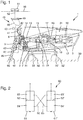
- Fig. 2 the principle of a cross-feed hydraulic system 60 is shown schematically.
- This comprises two hydraulic cylinders or hydraulic cylinders 61, 61 ', each with a plunger 62, 62', which divides the interior of the hydraulic cylinders 61, 61 'into an upper partial volume 63, 63' and a lower partial volume 64, 64 '.
- the stamps are acted upon from above with the force which, for example, applies the weight force or the respective force which results from a torque from the drive device 40.
- Hydraulic lines 65, 66 are provided between the upper partial volume 63 of the hydraulic cylinder 61 and the lower partial volume 64 'of the hydraulic cylinder 61' on the one hand and the lower partial volume 64 of the hydraulic cylinder 61 and the upper partial volume 63 'of the hydraulic cylinder 61' on the other hand, through which the hydraulic fluid communicates with each other in the sub-volumes connected to each other.
- This cross-feed hydraulic system thus has the effect that radial deflection, which is generated by the torque of the drive device 40, is prevented and the drive device 40 does not move with respect to the drive train.
- the crossover also has the effect that the absorbed sum of forces is zero.
Landscapes
- Engineering & Computer Science (AREA)
- Physics & Mathematics (AREA)
- General Physics & Mathematics (AREA)
- Life Sciences & Earth Sciences (AREA)
- Sustainable Development (AREA)
- Sustainable Energy (AREA)
- Chemical & Material Sciences (AREA)
- Combustion & Propulsion (AREA)
- Mechanical Engineering (AREA)
- General Engineering & Computer Science (AREA)
- Wind Motors (AREA)
Description
Die Erfindung betrifft einen Prüfstand zum Prüfen eines Triebstrangs einer Windenergieanlage, umfassend eine Antriebseinrichtung zum Einbringen einer Prüfleistung in den Triebstrang, die mit einem zu prüfenden Triebstrang lösbar verbindbar ist. Weiter betrifft die Erfindung ein Verfahren zum Prüfen eines Triebstrangs einer Windenergieanlage mit einem Prüfstand sowie einen Triebstrang einer Windenergieanlage.The invention relates to a test bench for testing a drive train of a wind energy installation, comprising a drive device for introducing a test power into the drive train, which can be releasably connected to a drive train to be tested. The invention further relates to a method for testing a drive train of a wind power plant with a test bench and a drive train of a wind power plant.
Im Bereich der Konstruktion von Windenergieanlagen werden in einigen Fällen Komponenten einer Windenergieanlage, und zwar mechanische, elektrische und/oder elektronische Komponenten, in einem Prüfstand geprüft, bevor die Windenergieanlage installiert und in Betrieb genommen wird. Solche Prüfstände, die einzelne Komponenten der Windenergieanlage oder auch eine komplett zusammengebaute Gondel bzw. ein komplett zusammengebautes Maschinenhaus prüfen, werden auch End-of-Line-Prüfstände genannt. Solche Prüfstände umfassen neben einer Steuerungselektronik einen oder mehrere Motoren, die eine Prüfleistung bzw. ein Drehmoment auf einen Triebstrang übertragen, insbesondere dort, wo bei der fertig installierten Windenergieanlage der Rotor angesetzt wird. Mittels solcher Prüfstände wird in einer Prüfstandssequenz getestet, ob die mechanischen, elektrischen und/oder elektronischen Komponenten vorgegebenen Richtwerten entsprechen. Die Prüfstandssequenz kann einige Stunden, beispielsweise bis zu 6 Stunden, dauern.In the field of the construction of wind energy plants, components of a wind energy plant, namely mechanical, electrical and / or electronic components, are tested in a test bench before the wind energy plant is installed and put into operation. Such test benches, which test individual components of the wind turbine or a completely assembled nacelle or a completely assembled nacelle, are also called end-of-line test benches. Such In addition to control electronics, test benches include one or more motors that transmit a test power or torque to a drive train, particularly where the rotor is attached to the fully installed wind turbine. Such test benches are used in a test bench sequence to test whether the mechanical, electrical and / or electronic components correspond to specified guide values. The test bench sequence can take a few hours, for example up to 6 hours.
Die im Prüfstand getesteten Komponenten oder Maschinenhäuser werden anschließend, nach bestandener Prüfung, zum Aufstellungsort transportiert und dort die Windenergieanlage aufgestellt.After passing the test, the components or machine houses tested on the test bench are then transported to the installation site and the wind turbine installed there.
Aus
In
Aus
Die bekannten End-of-Line-Prüfstände oder Prüfstände sind stationär auf dem Boden verankert und verfügen über Antriebseinrichtungen, die über eine flexible Kupplung mit dem Prüfling, also dem zu prüfenden Triebstrang, verbunden werden. Ein entsprechender Prüfstand ist beispielsweise aus
Idealerweise wird eine komplette Maschinengondel getestet. Diese ist mit mehr als 320 Tonnen Gewicht und Abmessungen von ca. 6x19m bei den unter den Bezeichnungen 5M und 6M vertriebenen Windenergieanlagen der Anmelderin nicht sehr mobil. Entsprechend aufwändig gestaltet sich die Vorbereitung und Prüfung im Prüfstand.Ideally, a complete machine nacelle should be tested. With a weight of more than 320 tons and dimensions of approx. 6x19m, it is not very mobile in the wind turbines of the applicant marketed under the names 5M and 6M. Corresponding Preparation and testing on the test bench is complex.
Es liegt der vorliegenden Erfindung die Aufgabe zugrunde, einen Prüfstand sowie ein Verfahren zum Prüfen eines Triebstrangs einer Windenergieanlage unter realistischen Bedingungen bereitzustellen, mit denen eine flexible Anpassung an verschiedene Windenergieanlagentypen möglich ist, wobei der konstruktive Aufwand gering gehalten werden soll.It is the object of the present invention to provide a test bench and a method for testing a drive train of a wind power plant under realistic conditions, with which flexible adaptation to different types of wind power plant is possible, the design effort being kept low.
Diese Aufgabe wird durch einen Prüfstand zum Prüfen eines Triebstrangs einer Windenergieanlage, umfassend eine Antriebseinrichtung zum Einbringen einer Prüfleistung in den Triebstrang, die mit einem zu prüfenden Triebstrang lösbar verbindbar ist, gelöst, der sich dadurch auszeichnet, dass die Antriebseinrichtung zur Prüfung eines Triebstrangs abnehmbar auf oder an dem Triebstrang auf- oder angesetzt und gelagert ist oder wird, wobei bei auf- oder angesetzter Antriebseinrichtung ein überwiegender Teil der Gewichtskraft der Antriebseinrichtung auf dem Triebstrang lastet.This object is achieved by a test bench for testing a drive train of a wind energy installation, comprising a drive device for introducing a test power into the drive train, which can be releasably connected to a drive train to be tested, which is characterized in that the drive device for testing a drive train can be removed or is mounted on or attached to the drive train and is or is supported, with a predominant part of the weight of the drive device bearing on the drive train when the drive device is attached or attached.
Anders als im Stand der Technik ist der erfindungsgemäße Prüfstand somit nicht stationär auf dem Boden verankert, sondern weist eine, vorzugsweise in abgenommenen Zustand frei bewegliche, Antriebseinrichtung auf, die zur Prüfung eines Triebstrangs auf oder an den Triebstrang auf- oder angesetzt wird. Dabei wird außerdem ein überwiegender Teil der Gewichtskraft, also insbesondere über 50% der Gewichtskraft, der Antriebseinrichtung so gelagert, dass sie auf dem Triebstrang lastet.In contrast to the prior art, the test bench according to the invention is therefore not anchored stationary on the floor, but rather has a drive device, which is preferably freely movable in the removed state, and which is attached to or attached to the drive train for testing a drive train. In addition, a predominant part of the weight, that is to say in particular over 50% of the weight, of the drive device is mounted such that it bears on the drive train.
Im Vergleich mit der üblichen Vorgehensweise, dass die Antriebseinrichtung über eine flexible Kupplung mit dem Prüfling verbunden ist, ermöglicht dies eine deutlich realistischere Prüfung des Triebstrangs.In comparison with the usual procedure that the drive device is connected to the test object via a flexible coupling, this enables a significantly more realistic test of the drive train.
Im Rahmen der Erfindung kann ein einzelner Triebstrang, also eine Rotorwelle oder ein rotorwellenloser Triebstrang mit gegebenenfalls weiteren Komponenten, etwa einem Getriebe, einer schnellen Welle usw., geprüft werden, der oder die allein oder eingebaut in eine Maschinengondel oder ein Maschinengehäuse ist oder sind.Within the scope of the invention, a single drive train, i.e. a rotor shaft or a drive shaft without rotor shaft with possibly further components, such as a gearbox, a fast shaft etc., can be tested, which is or is alone or installed in a machine nacelle or a machine housing.
Zum An- oder Aufsetzen der Antriebseinrichtung an oder auf den Triebstrang dient vorzugsweise ein Antriebsflansch des Triebstrangs, an bzw. auf dem die Antriebseinrichtung befestigt wird. Der Antriebsflansch kann bspw. an einer Rotorwelle angeordnet sein und im Betrieb der Windenergieanlage mit einer Rotornabe verbunden sein, oder bei einem rotorwellenlosen Antrieb ebenfalls zur Befestigung einer Rotornabe dienen. Der Antriebsflansch kann alternativ auch Teil der Rotornabe sein, die in diesem Fall zum zu prüfenden Triebstrang gehört. Die Antriebseinheit kann auch in geeigneter Weise an dem einen oder den mehreren Flanschen für das Rotorblatt oder die Rotorblätter an der Rotornabe angreifen.A drive flange of the drive train, on or on which the drive device is fastened, is preferably used to attach or place the drive device on or on the drive train. The drive flange can be arranged, for example, on a rotor shaft and can be connected to a rotor hub during operation of the wind energy installation, or can also serve to fasten a rotor hub in the case of a drive without a rotor shaft. Alternatively, the drive flange can also be part of the rotor hub, which in this case belongs to the drive train to be tested. The drive unit can also engage in a suitable manner on the one or more flanges for the rotor blade or the rotor blades on the rotor hub.
Vorzugsweise entspricht der im aufgesetzten Zustand auf dem Triebstrang lastende Teil der Gewichtskraft der Antriebseinrichtung einer Gewichtskraft eines Rotors der Windenergieanlage. Damit wird der Triebstrang unter realistischen Bedingungen geprüft. Der mobile erfindungsgemäße Prüfstand bzw. dessen Antriebseinrichtung weist daher bevorzugt ein Gewicht auf, das in der Größenordnung oder etwas über dem Gewicht des Rotors der fertig montierten Windenergieanlage liegt.The part of the weight of the drive device which bears on the drive train in the mounted state preferably corresponds to a weight of a rotor of the wind power installation. This tests the drive train under realistic conditions. The mobile test stand according to the invention or its drive device therefore preferably has a weight which is of the order of magnitude or somewhat above the weight of the rotor of the fully assembled wind energy installation.
Bei modernen Windenergieanlagen, beispielsweise den unter der Typenbezeichnung 5M oder 6M der Anmelderin vertriebenen Windenergieanlagen, weist das Maschinenhaus ein Gewicht von über 300 Tonnen auf. Der Rotor bei der 5M weist ein Gewicht von 130 Tonnen auf. Ein kompakt gebauter, insbesondere fliegend gelagerter, Prüfantrieb mit 50 bis 150 Tonnen Gewicht ist dabei deutlich mobiler als eine Gondel von mehr als 300 Tonnen Gewicht. Da der Prüfstand außerdem eine wesentlich geringere Betriebsstundenzahl als die Windturbinen aufweist, kann er deutlich leichter und kompakter als die WEA-Gondel ausgeführt werden.In modern wind turbines, for example the wind turbines marketed by the applicant under the type designation 5M or 6M, the machine house has a weight of over 300 tons. The rotor of the 5M has a weight of 130 Tons on. A compactly built, especially overhung, test drive with a weight of 50 to 150 tons is significantly more mobile than a gondola with a weight of more than 300 tons. Since the test bench also has a significantly lower number of operating hours than the wind turbines, it can be made much lighter and more compact than the wind turbine nacelle.
Das Gewicht bzw. das Massenmoment des Antriebs wirkt vorzugsweise maximal so, dass es dem Rotor der kleinsten zu testenden Anlage entspricht. Gegebenenfalls wird die Masse vorteilhafterweise durch Trimmgewichte auf Werte größerer Rotoren angepasst. Dadurch sind realistischere Gesamtmassen, Gondelverformungen und gegebenenfalls sogar Antriebsstrang-Trägheiten durch die simulierte Rotormasse simulierbar.The weight or the mass moment of the drive preferably acts at most so that it corresponds to the rotor of the smallest system to be tested. If necessary, the mass is advantageously adapted to values of larger rotors by means of trim weights. As a result, more realistic overall masses, nacelle deformations and possibly even powertrain inertia can be simulated by the simulated rotor mass.
Alternativ, wenn der Antrieb mehr als der Rotor der kleinsten zu testenden Anlage wiegt, wird ein Teil des Gewichts direkt auf den Erdboden übertragen.Alternatively, if the drive weighs more than the rotor of the smallest system under test, part of the weight is transferred directly to the ground.
Vorzugsweise ist die Lagerung der Antriebseinrichtung auf dem Triebstrang eine fliegende Lagerung. Damit wird der Triebstrang nicht unnötig oder übermäßig axial belastet. Dies trägt auch zur Schonung des Triebstrangs bei.The mounting of the drive device on the drive train is preferably a floating mounting. This means that the drive train is not unnecessarily or excessively axially loaded. This also helps to protect the drive train.
Der besondere Vorteil bei der fliegenden Lagerung besteht darin, dass die zeitaufwändige genaue Ausrichtung der Antriebseinheit auf den Triebstrang entfällt.The particular advantage of flying storage is that there is no need for the time-consuming, precise alignment of the drive unit to the drive train.
Vorteilhafterweise sind Zwischenflansche für unterschiedliche Anlagen vorgesehen. Dies ermöglicht eine flexible Einsetzbarkeit des Prüfstands, wenn die Anlagen verschiedene Flansche aufweisen.Intermediate flanges are advantageously provided for different systems. This enables the test bench to be used flexibly if the systems have different flanges.
Vorzugsweise weist die Antriebseinrichtung ein Großzahnrad auf, das auf einen Antriebsflansch aufsetzbar ist, sowie ein oder mehrere Ritzel, die am oder im Umfang des Großzahnrads in eine Außenzahnung oder Innenzahnung des Großzahnrads eingreifen. Die Ritzel sind vorzugsweise gleichmäßig um den Umfang des Großzahnrades verteilt. Durch die Mehrzahl oder Vielzahl von Ritzeln ist jedes Ritzel nur mit einem kleinen Teil an der Einbringung der Prüfleiste bzw. des Prüfdrehmoments auf das Großzahnrad und damit den Triebstrang beteiligt. Dies schont das Material der Antriebseinrichtung. Ebenfalls lässt sich auf diese Weise eine gleichmäßige Belastung in Umfangsrichtung erreichen, wobei Unwuchten, die für die Antriebseinrichtung und den Prüfling schädlich sind, vermieden werden.The drive device preferably has a large gearwheel which can be placed on a drive flange, and one or more pinions which engage in an external toothing or internal toothing of the large gearwheel on or in the circumference of the large gearwheel. The pinions are preferably evenly distributed around the circumference of the large gear. Due to the plurality or number of pinions, each pinion is only involved with a small part in the introduction of the test strip or the test torque onto the large gear and thus the drive train. This protects the material of the drive device. A uniform load in the circumferential direction can also be achieved in this way, unbalances which are harmful to the drive device and the test specimen being avoided.
Alternativ ist ebenfalls bevorzugt ein elektrischer Direktantrieb ohne Verzahnung vorgesehen.Alternatively, an electrical direct drive without teeth is also preferably provided.
Die Antriebseinrichtung weist einen oder mehrere, insbesondere hydraulische oder elektrische, Antriebsmotoren auf. Bei hydraulischen Antriebsmotoren ist vorzugsweise eine stationäre Hydraulikeinheit zur Versorgung der hydraulischen Antriebsmotoren vorgesehen.The drive device has one or more, in particular hydraulic or electrical, drive motors. In the case of hydraulic drive motors, a stationary hydraulic unit for supplying the hydraulic drive motors is preferably provided.
Vorzugsweise wirken die Antriebsmotoren jeweils auf ein Ritzel, wobei die Antriebsmotoren insbesondere mittels einer hydraulischen Ringleitung oder durch eine elektronische Steuerung synchronisiert sind. Eine hydraulische Ringleitung, die die hydraulischen Antriebsmotoren miteinander verbindet, sorgt dafür, dass eine Prüfleistungseinwirkung gleichmäßig um den Umfang verteilt stattfindet. Eine elektronische Steuerung, die die Elektromotoren synchronisiert, ist ebenfalls erfindungsgemäß einsetzbar. Sie kann insbesondere erhöhte Lastzustände einzelner Elektromotoren erkennen, reduzieren und durch die anderen Elektromotoren kompensieren, so dass die Lasteinwirkung vergleichmäßigt wird.The drive motors preferably each act on a pinion, the drive motors being synchronized in particular by means of a hydraulic ring line or by an electronic control. A hydraulic ring line, which connects the hydraulic drive motors with each other, ensures that the test power is distributed evenly around the circumference. An electronic control that synchronizes the electric motors can also be used according to the invention. In particular, it can detect and reduce increased load states of individual electric motors and compensate by the other electric motors, so that the load is evened out.
Vorteilhafterweise umfasst die Antriebseinrichtung eine Drehmomentenstütze, die insbesondere zwei sich auf dem Boden abstützende Stützfüße aufweist. Diese Drehmomentenstütze stützt einerseits den kleineren Teil der Gewichtskraft der Antriebseinrichtung gegenüber dem Boden ab und fängt das Drehmoment auf, das durch die Antriebseinrichtung auf den Prüfling ausgeübt wird.The drive device advantageously comprises a torque support, which in particular has two support feet which are supported on the floor. This torque support on the one hand supports the smaller part of the weight of the drive device against the ground and absorbs the torque that is exerted by the drive device on the test specimen.
Vorzugsweise weist die Drehmomentenstütze eine Zwangslast-Kompensation, insbesondere eine Crossfeed-Hydraulik oder Piezoelemente, auf. Die zwangslastfreie Einleitung von Drehmomenten bedeutet, dass durch die erforderliche Abstützung des Drehmoments am Boden keine Querkräfte in die Struktur eingeleitet werden, so dass der Triebstrang nicht durch ein radiales Ausweichen der Antriebseinrichtung unter der Einwirkung des eingebrachten Prüfdrehmoments verformt oder belastet wird. Dies erreicht man bevorzugt durch eine Crossfeed-Hydraulik, bei der zwei Hydraulikzylinder im Kraftfluss der Drehmomentenstütze kreuzweise so miteinander verschaltet werden, dass sie nur zwei entgegengesetzte Kräfte von gleichem Betrag aufnehmen können, sodass die Kräftesumme stets Null beträgt. Dadurch ergibt sich eine Querkraftfreiheit. Die Zwangslastfreiheit bzw. Zwangskraftfreiheit dient dazu, den Prüfling zu schonen. Dieser wird daher nicht bereits in der Prüfung vorgeschädigt. Anstelle einer Crossfeed-Hydraulik kann eine Zwangslast-Kompensation vorteilhafterweise auch durch Piezoelemente geschehen, die hochbelastbar und schnell steuerbar sind.The torque arm preferably has a forced load compensation, in particular a crossfeed hydraulic system or piezo elements. The introduction of torques free of constraint means that the required support of the torque on the ground means that no transverse forces are introduced into the structure, so that the drive train is not deformed or stressed by a radial deflection of the drive device under the influence of the test torque. This is preferably achieved by means of a crossfeed hydraulic system, in which two hydraulic cylinders in the power flow of the torque arm are cross-connected so that they can only absorb two opposite forces of the same amount, so that the total force is always zero. This results in freedom from lateral forces. The freedom from constraint load or freedom from constraint serves to protect the test specimen. This is therefore not pre-damaged during the test. Instead of a crossfeed hydraulic system, a forced load compensation can advantageously also be carried out by piezo elements which are highly loadable and can be controlled quickly.
Wenn die Maschinengondel ausreichend schwer ist, kann in einer vorteilhaften einfachen Ausführung der Transportträger der Gondel zur Abstützung des Triebstrangdrehmoments ausreichen. Andernfalls ist durch geeignete konstruktive Maßnahmen, z. B. durch Verbreiterung der Aufstandsfläche für eine sichere Einleitung des Drehmoments in den Boden zu sorgen.If the machine nacelle is sufficiently heavy, the transport carrier of the nacelle can be sufficient to support the drive train torque in an advantageous simple embodiment. Otherwise is by suitable design measures, e.g. B. by widening the footprint to ensure a safe introduction of the torque in the ground.
In einer vorteilhaften Weiterbildung weist die Antriebseinrichtung eine Haltevorrichtung auf, an der die Antriebseinrichtung anhängbar ist, wobei die Haltevorrichtung insbesondere eine Mehrzahl von Halteöffnungen oder ein Langloch, insbesondere mit Raststellen, für ein Hebezeug oder ein anderes Hebemittel aufweist, mittels denen eine Achsneigung der Antriebseinrichtung im hängenden Zustand einstellbar ist. Mit der Haltevorrichtung ist es möglich, die Antriebseinrichtung des Prüfstands beispielsweise in einer Prüfhalle an einem Deckenschienensystem, das eine hohe Traglast aufweist, frei zu verfahren und beispielsweise von einem Triebstrang zum nächsten Triebstrang zu bringen, ohne dass die Triebstränge oder Gondeln selbst bewegt werden müssen. Die Achsneigung kann vorzugsweise zwischen 0° und 10°, insbesondere zwischen 4° und 7°, verstellt werden.In an advantageous development, the drive device has a holding device to which the drive device can be attached, the holding device in particular having a plurality of holding openings or an elongated hole, in particular with latching points, for a hoist or other lifting means, by means of which an axis inclination of the drive device in the hanging state is adjustable. With the holding device, it is possible to move the drive device of the test bench freely in a test hall on a ceiling rail system that has a high load capacity, for example, and to move it from one drive train to the next drive train without having to move the drive trains or nacelles themselves. The axis inclination can preferably be adjusted between 0 ° and 10 °, in particular between 4 ° and 7 °.
Das Merkmal, dass die Haltevorrichtung eine Mehrzahl von Halteöffnungen für einen Hebezeug oder ein anderes Hebemittel oder ein entsprechendes, mit Raststellen versehenes Langloch aufweist, bedeutet, dass abhängig davon, welche Halteöffnung für das Hebezeug verwendet wird, der Schwerpunkt der Antriebseinrichtung sich an einer anderen Stelle unter der gewählten Halteöffnung befindet, so dass die Antriebseinrichtung bei jeder Halteöffnung eine unterschiedliche Achsneigung aufweist. Die Halteöffnungen oder Raststellen sind insbesondere so angeordnet, dass vorbestimmte Achsneigungen von bekannten Triebstrangtypen und insbesondere Gondeltypen verschiedener Windenergieanlagentypen einstellbar sind. Die Antriebseinrichtung des erfindungsgemäßen Prüfstands kann dann so angehoben werden, dass sie bereits die korrekte Achsneigung aufweist und somit korrekt fluchtend auf den Triebstrang der zu prüfenden Windenergieanlage aufgesetzt werden kann.The feature that the holding device has a plurality of holding openings for a lifting device or another lifting means or a corresponding elongated hole provided with locking points means that, depending on which holding opening is used for the lifting device, the center of gravity of the drive device is at a different location is located under the selected holding opening, so that the drive device has a different axis inclination for each holding opening. The holding openings or locking points are in particular arranged in such a way that predetermined axis inclinations of known drive train types and in particular gondola types of different types of wind energy plants can be set. The drive device of the test bench according to the invention can then be raised so that it already has the correct axis inclination has and can thus be correctly aligned on the drive train of the wind turbine to be tested.
Die erfindungsgemäße Antriebseinrichtung des erfindungsgemäßen Prüfstands ist unabhängig von der Achsneigung der zu prüfenden Anlage einsetzbar und es sind keine großen stationären Prüfstands-Strukturen erforderlich. Der Prüfstand ist flexibel im Einsatz und könnte gegebenenfalls schon vorinstalliert werden, während der Prüfstandsplatz noch durch einen anderen Prüfling belegt ist.The drive device according to the invention of the test bench according to the invention can be used regardless of the axis inclination of the system to be tested and no large stationary test bench structures are required. The test stand is flexible in use and could possibly be preinstalled while the test stand space is still occupied by another test object.
Mittels des mobilen erfindungsgemäßen Prüfstands kann eine Prüfung eines Triebstrangs, gegebenenfalls in der Gondel, auch vor Ort erfolgen, wenn die Antriebseinheit mittels eines Krans auf den Triebstrang aufgesetzt wird. Dabei ist eine Energieversorgung und eine Drehmomentabstützung zu realisieren. Bei großen Offshore-Projekten ist es auch möglich, den gewünschten End-of-Line-Test an der Kaikante eines Hafens mit entsprechender Infrastruktur durchzuführen.Using the mobile test stand according to the invention, a drive train, possibly in the nacelle, can also be tested on site if the drive unit is placed on the drive train by means of a crane. An energy supply and torque support must be implemented. For large offshore projects, it is also possible to carry out the desired end-of-line test at the quay edge of a port with the appropriate infrastructure.
Der erfindungsgemäße Prüfstand erfordert in Bezug auf seine elektrische bzw. hydraulische Energieversorgung eine vorhandene Infrastruktur, ebenso gegebenenfalls einen Netzanschluss, in den der Generator des Prüflings die Energie einspeist. Es ist auch ein Kreisschluss möglich, bei dem der Großteil der benötigten Antriebsenergie durch den Generator der geprüften Windenergieanlage bereitgestellt wird.With regard to its electrical or hydraulic energy supply, the test stand according to the invention requires an existing infrastructure, and possibly also a network connection, into which the generator of the test object feeds the energy. It is also possible to create a circuit in which the majority of the drive energy required is provided by the generator of the tested wind turbine.
Die der Erfindung zugrunde liegende Aufgabe wird auch durch ein Verfahren zum Prüfen eines Triebstrangs einer Windenergieanlage mit einem Prüfstand, der insbesondere erfindungsgemäß wie vorstehend beschrieben ausgebildet ist, gelöst, das sich dadurch auszeichnet, dass eine Antriebseinrichtung des Prüfstands auf oder an einen Triebstrang aufgesetzt oder angesetzt wird, wobei bei der Lagerung ein überwiegender Teil der Gewichtskraft der Antriebseinrichtung auf dem Triebstrang lastet. Die Antriebseinrichtung ist dabei insbesondere frei beweglich ausgebildet. Das Verfahren weist die gleichen Vorteile, Merkmale und Eigenschaften auf, wie der erfindungsgemäße Prüfstand.The object on which the invention is based is also achieved by a method for testing a drive train of a wind energy installation with a test bench, which is designed in particular according to the invention as described above, which is characterized in that a drive device of the test bench is on or on a drive train is attached or attached, a predominant part of the weight of the drive device being loaded on the drive train during storage. The drive device is in particular designed to be freely movable. The method has the same advantages, features and properties as the test bench according to the invention.
Vorzugsweise entspricht der auf dem Triebstrang lastende Teil der Gewichtskraft der Antriebseinrichtung einer Gewichtskraft eines Rotors der Windenergieanlage. Damit ist eine realitätsnahe Simulation des Windenergieanlagenbetriebs möglich.The part of the weight force of the drive device which bears on the drive train preferably corresponds to a weight force of a rotor of the wind energy installation. This enables realistic simulation of wind turbine operation.
Das erfindungsgemäße Verfahren erlaubt es ebenfalls, dass vorteilhafterweise die Prüfung mit der Antriebseinrichtung an mehreren Triebsträngen erfolgt, wobei jeweils die Antriebseinrichtung von einem geprüften Triebstrang zu einem zu prüfenden Triebstrang verfahren wird.The method according to the invention also allows the test with the drive device to be advantageously carried out on a plurality of drive trains, the drive device in each case being moved from a tested drive train to a drive train to be tested.
Die der Erfindung zugrunde liegende Aufgabe wird schließlich durch einen Triebstrang einer Windenergieanlage gelöst, der sich dadurch auszeichnet, dass er mittels eines zuvor beschriebenen erfindungsgemäßen Verfahrens und/oder mittels eines zuvor beschriebenen erfindungsgemäßen Prüfstands geprüft worden ist. Dieser Triebstrang hat somit eine Prüfung unter realistischen Lastbedingungen überstanden und weist damit eine geringere Ausfallwahrscheinlichkeit auf, als in üblichen stationären Prüfständen geprüfte Triebstränge. Auch eine Windenergieanlage, die einen entsprechenden erfindungsgemäßen Triebstrang aufweist, löst die der Erfindung zugrunde liegende Aufgabe.The object on which the invention is based is finally achieved by a drive train of a wind energy installation which is distinguished in that it has been tested by means of a previously described method according to the invention and / or by means of a previously described test bench according to the invention. This drive train has thus passed a test under realistic load conditions and is therefore less likely to fail than drive trains tested in conventional stationary test benches. A wind energy installation which has a corresponding drive train according to the invention also achieves the object on which the invention is based.
Weitere Merkmale der Erfindung werden aus der Beschreibung erfindungsgemäßer Ausführungsformen zusammen mit den Ansprüchen und den beigefügten Zeichnungen ersichtlich. Erfindungsgemäße Ausführungsformen können einzelne Merkmale oder eine Kombination mehrerer Merkmale erfüllen.Further features of the invention will become apparent from the description of embodiments according to the invention together with the claims and the accompanying drawings. Embodiments according to the invention can fulfill individual features or a combination of several features.
Die Erfindung wird nachstehend ohne Beschränkung des allgemeinen Erfindungsgedankens anhand von Ausführungsbeispielen unter Bezugnahme auf die Zeichnungen beschrieben, wobei bezüglich aller im Text nicht näher erläuterten erfindungsgemäßen Einzelheiten ausdrücklich auf die Zeichnungen verwiesen wird. Es zeigen:
- Fig. 1
- eine schematische Querschnittsdarstellung durch eine Gondel einer Windenergieanlage mit darauf aufgesetztem erfindungsgemäßen Prüfstand und
- Fig. 2
- eine schematische Darstellung einer Crossfeed-Hydraulik.
- Fig. 1
- is a schematic cross-sectional view through a nacelle of a wind power plant with the inventive test stand and
- Fig. 2
- a schematic representation of a crossfeed hydraulic system.
In den Zeichnungen sind jeweils gleiche oder gleichartige Elemente und/oder Teile mit denselben Bezugsziffern versehen, so dass von einer erneuten Vorstellung jeweils abgesehen wird.In the drawings, the same or similar elements and / or parts are provided with the same reference numbers, so that a renewed presentation is not given.
In
Der zu prüfende Triebstrang beginnt mit einer Rotorwelle 13, die in einem als Wälzlager ausgebildeten Rotorlager 14 drehbar gelagert ist. Bei der Windenergieanlage MD70 der Anmelderin ist das Rotorlager 14 als Festlager ausgebildet, das nur wenige Millimeter Spiel in axialer Richtung der Rotorwelle 13 erlaubt. Die Rotorwelle 13 treibt ein Getriebe 15, das die langsame Drehbewegung der Rotorwelle in eine schnelle Drehbewegung einer Generatorwelle 19, die mit Kupplungen dargestellt ist, umsetzt, die wiederum einen Generator 20 zur Stromerzeugung antreibt, der mit einem Wärmetauscher 21 ausgestattet ist.The drive train to be tested begins with a
Das Getriebe 15 weist außerdem eine Rotorbremse 17 und einen Schleifringüberträger 18 auf sowie zwei elastische Getriebeaufhängungen bzw. Auflager 16, von denen eines in
Das Auflager bzw. die elastische Getriebeaufhängung 16 ist konventionell gestaltet und besteht aus hohlzylindrischen Elastomerkörpern aus zwei halbzylindrischen Teilkörpern, die um einen zylindrischen Bolzen herum angeordnet sind. Mit seinen zylindrischen Lagern, deren Zylinderachse parallel zur Rotorwelle 13 ausgerichtet ist, handelt es sich bei dem Auflager 16 um ein Loslager, da es aufgrund seiner Weichheit in dieser Richtung nur wenig Rotorschubkraft in Richtung der Rotorwellenachse aufnimmt.The support or the
Die Gondel 3 ist zur Prüfung auf einem Lagerrahmen 31 angeordnet und mittels Füßen 32, 32' und Bolzen 33, 33' gegenüber dem Boden fest abgestützt.The
Auf einem an der Rotorwelle 13 angeordneten Antriebsflansch 5 sitzt eine erfindungsgemäße Antriebseinrichtung 40 eines erfindungsgemäßen Prüfstands 1 auf. Mit 6 ist ein Pitchschrank für die Blattverstellung bezeichnet, der am Antriebsflansch 5 befestigt ist. In einem Gehäuse weist die Antriebseinrichtung ein Großzahnrad 41 auf, das auf dem Antriebsflansch 5 der Rotorwelle 13 aufsitzt. Eine Drehung des Großzahnrads 41 führt somit auch zu einer Drehung des Triebstrangs. Um den Umfang des Großzahnrads 41 verteilt sind mehrere Ritzel 42, also kleine Zahnräder, angeordnet, deren Zahnräder auf die Zahnräder des Großzahnrads 41 einwirken. Jedes Ritzel ist mit einem Motor 43 versehen, der das Ritzel 42 antreibt. Die Motoren 43 können elektrisch oder hydraulisch sein. Es sind in der Schnittdarstellung in
Die Antriebsmotoren benötigen eine nicht dargestellte Energieversorgung, z. B. mittels elektrischer Kabel oder hydraulischer Hochdruckschläuche. Das beanspruchte Merkmal "frei beweglich" umfasst, dass es durch die Energieversorgung zu Einschränkungen, z. B. durch die Kabel-/Schlauchlänge kommen kann. Funktionell ist die Antriebseinrichtung 40 aber gegenüber dem Prüfling in allen Richtungen verfahrbar und drehbar.The drive motors require an energy supply, not shown, e.g. B. by means of electrical cables or hydraulic high pressure hoses. The claimed feature "freely movable" includes that it is limited by the energy supply, z. B. can come through the cable / hose length. Functionally, however, the
Das Gehäuse bzw. die Antriebseinrichtung 40 weist eine Drehmomentenstütze 45 auf, die mit einem Fuß 46 oder Stützfuß auf dem Boden 30 aufsitzt. Diese Drehmomentenstütze 45 sorgt dafür, dass das Drehmoment, das durch das Großzahnrad 41 auf den Triebstrang in der Gondel 3 übertragen wird, zum Boden 30 hin abgeleitet wird. Die Drehmomentenstütze weist außerdem eine Cross-feed-Hydraulik 60 auf, die ein radiales Ausweichen verhindert und eine Zwangslastkompensation bewirkt.The housing or the
Die Antriebseinrichtung 40 weist ferner eine Haltevorrichtung 48 an ihrem oberen Ende auf, in deren oberen Bereich mehrere Halteöffnungen 49 nebeneinander angeordnet sind. Die Halteöffnungen 49 dienen dazu, einen Tragehaken eines Hebezeugs 52 aufzunehmen, so dass die Antriebseinrichtung 40 über das Hebezeug 52 von einer Laufkatze 51 auf einer Trageschiene 50 gehalten und verfahren werden kann. Die verschiedenen Halteöffnungen 49 sind an verschiedenen Positionen in Längsrichtung angeordnet, so dass durch Auswahl einer bestimmten Halteöffnung 49 eine bestimmte Achsneigung der Antriebseinrichtung 40 eingestellt wird. Damit kann die Achsneigung schon vor dem Ankoppeln an einen Triebstrang an die Achsneigung des Triebstrangs in dem jeweiligen Maschinenhaus typgerecht angepasst werden.The
Als Hebevorrichtung können Deckenkrane mit Ketten, Stahlseilen oder Kranschlupfen als Hebezeug vorgesehen sein. Alternativ können aber auch Rollwagen mit entsprechenden Justiervorrichtungen zur Höhen- und Winkeleinstellung vorgesehen sein. Dies ist insbesondere dann vorteilhaft, wenn kein Deckenkran mit ausreichender Traglast zur Verfügung steht.As a lifting device, overhead cranes with chains, steel cables or crane slips can be provided. Alternatively, however, trolleys can also be provided with corresponding adjustment devices for height and angle adjustment. This is particularly advantageous if no overhead crane with sufficient load capacity is available.
In
Es sind Hydraulikleitungen 65, 66 zwischen dem oberen Teilvolumen 63 des Hydraulikzylinders 61 und dem unteren Teilvolumen 64' des Hydraulikzylinders 61' einerseits und dem unteren Teilvolumen 64 des Hydraulikzylinders 61 und dem oberen Teilvolumen 63' des Hydraulikzylinders 61' andererseits vorgesehen, durch die die Hydraulikflüssigkeit in den jeweils miteinander verbundenen Teilvolumina miteinander kommuniziert. Dies resultiert darin, dass ein vermehrter Druck auf beispielsweise den Stempel 62 des Hydraulikzylinders 61 zu einer weiteren Verringerung des unteren Teilvolumens 64 führt. Über die Verbindungsleitung 66 wird dieser Druck auf den Stempel 62' im Hydraulikzylinder 61' weitergeleitet, der ebenfalls weiterbelastet wird. Damit kann beispielsweise ein Drehmoment kompensiert werden, das derart wirkt, dass das Drehmoment den Stempel 62' eigentlich nach oben bewegen möchte. Diese Cross-feed-Hydraulik bewirkt somit, dass ein radiales Ausweichen, das durch das Drehmoment der Antriebseinrichtung 40 erzeugt wird, verhindert wird und sich die Antriebseinrichtung 40 bezüglich des Triebstrangs nicht bewegt. Die Überkreuzung bewirkt auch, dass die aufgenommene Kräftesumme gleich Null ist.
Alle genannten Merkmale, auch die den Zeichnungen allein zu entnehmenden sowie auch einzelne Merkmale, die in Kombination mit anderen Merkmalen offenbart sind, werden allein und in Kombination als erfindungswesentlich angesehen. Erfindungsgemäße Ausführungsformen können durch einzelne Merkmale oder eine Kombination mehrerer Merkmale erfüllt sein.All of the features mentioned, including those that can be seen in the drawings alone and also individual features that are disclosed in combination with other features, are considered to be essential to the invention, alone and in combination. Embodiments according to the invention can be fulfilled by individual features or a combination of several features.
- 11
- Prüfstandtest bench
- 33rd
- Gondelgondola
- 55
- AntriebsflanschDrive flange
- 66
- PitchschrankPitch cabinet
- 77
- TurmkopfdrehkranzTower head slewing ring
- 99
- AzimutverstellmotorenAzimuth adjustment motors
- 1111
- AzimutbremsenAzimuth brakes
- 1212th
- MaschinenträgerMachine carrier
- 1313
- RotorwelleRotor shaft
- 1414
- RotorlagerRotor bearings
- 1515
- Getriebetransmission
- 1616
- elastische Getriebeaufhängungelastic gear suspension
- 1717th
- RotorbremseRotor brake
- 1818th
- SchleifringüberträgerSlip ring transmitter
- 1919th
- Generatorwelle mit KupplungenGenerator shaft with clutches
- 2020th
- Generatorgenerator
- 2121
- WärmetauscherHeat exchanger
- 3030th
- Bodenground
- 3131
- LagerrahmenBearing frame
- 32, 32'32, 32 '
- Fußfoot
- 33, 33'33, 33 '
- Bolzenbolt
- 4040
- AntriebseinrichtungDrive device
- 4141
- GroßzahnradLarge gear
- 4242
- Ritzelpinion
- 4343
- AntriebsmotorDrive motor
- 4545
- DrehmomentenstützeTorque support
- 4646
- Fußfoot
- 4848
- HaltevorrichtungHolding device
- 4949
- HalteöffnungHolding opening
- 5050
- TrageschieneMounting rail
- 5151
- LaufkatzeTrolley
- 5252
- HebezeugHoist
- 6060
- Crossfeed-HydraulikCrossfeed hydraulics
- 61, 61'61, 61 '
- HydraulikzylinderHydraulic cylinder
- 62, 62'62, 62 '
- Stempelstamp
- 63, 63'63, 63 '
- oberes Teilvolumenupper part volume
- 64, 64'64, 64 '
- unteres Teilvolumenlower partial volume
- 65, 6665, 66
- HydraulikleitungHydraulic line
Claims (13)
- A test bench (1) for testing a drive train of a wind energy installation, comprising a drive device (40) for introducing a test power into the drive train, which drive device (40) can be releasably connected to a drive train to be tested, wherein, in order to test a drive train, the drive device (40) is releasably mounted on or to, or attached on or to and supported by, the drive train, characterised in that, when the drive device (40) is in the mounted or attached condition, a predominant part of the weight force of the drive device (40) bears on the drive train and the drive device (40) comprises one or more drive motors (43), in particular one or more hydraulic or electric drive motors (43).
- The test bench (1) according to claim 1, characterised in that the drive device (40) is freely movable when it is in the removed condition.
- The test bench (1) according to claim 1 or 2, characterised in that the part of the weight force of the drive device (40) which in the mounted condition is borne by the drive train corresponds to a weight force of a rotor of the wind energy installation.
- The test bench (1) according to any one of the claims 1 to 3, characterised in that the bearing of the drive device (40) on the drive train is a cantilever type bearing.
- The test bench (1) according to any one of the claims 1 to 4, characterised in that the drive device (40) comprises a large gearwheel (41) which can be mounted on a drive flange (5), as well as one or more pinions (42) which engage on or in the circumference of the large gear wheel (41) in an external toothing or an internal toothing of the large gearwheel (41).
- The test bench (1) according to any one of the claims 1 to 5, characterised in that the drive motors (43) each act on a respective pinion (42), wherein the drive motors (43) are synchronised, in particular by means of a hydraulic ring mains or by an electronic control facility.
- The test bench (1) according to any one of the claims 1 to 6, characterised in that the drive device (40) comprises a torque support (45) which in particular comprises two support feet (46) which are supported on the ground.
- The test bench (1) according to claim 7, characterised in that the torque support (45) comprises a forced load compensation, in particular a cross-feed hydraulic system (60) or piezo elements.
- The test bench (1) according to any one of the claims 1 to 8, characterised in that the drive device (40) comprises a holding device (48) from which the drive device (40) can be suspended, in particular wherein the holding device (48) comprises a plurality of retaining openings (49) or an elongated hole, in particular with latching positions, for a lifting apparatus (52), by means of which an axial inclination of the drive device (40) can be adjusted when the drive device is in the suspended condition.
- A method of testing a drive train of a wind energy installation using a test bench (1), in particular according to any one of the claims 1 to 9, wherein a drive device (40) of the test bench (1) is mounted on or to, or attached on or to a drive train, characterised in that in the mounted condition, a predominant part of the weight force of the drive device (40) is borne by the drive train and the drive device (40) comprises one or more drive motors (43), in particular one or more hydraulic or electric drive motors (43).
- The method according to claim 10, characterised in that the part of the weight force of the drive device (40) which is borne by the drive train corresponds to a weight force of a rotor of the wind energy installation.
- The method according to claim 10 or 11, characterised in that the test using the drive device (40) is carried out on a plurality of drive trains, wherein in each case the drive device (40) is moved from a drive train which has been tested to a drive train that is to be tested.
- A drive train of a wind energy installation, characterised in that it has been tested by means of a method according to any one of the claims 10 to 12 and / or by means of a test bench (1) according to any one of the claims 1 to 9.
Applications Claiming Priority (2)
| Application Number | Priority Date | Filing Date | Title |
|---|---|---|---|
| DE102012212844.1A DE102012212844A1 (en) | 2012-07-23 | 2012-07-23 | Test bench and method for testing a drive train of a wind energy plant |
| PCT/EP2013/001960 WO2014015941A1 (en) | 2012-07-23 | 2013-07-04 | Test bench and method for testing the drive train of a wind turbine |
Publications (2)
| Publication Number | Publication Date |
|---|---|
| EP2875329A1 EP2875329A1 (en) | 2015-05-27 |
| EP2875329B1 true EP2875329B1 (en) | 2020-04-22 |
Family
ID=48793160
Family Applications (1)
| Application Number | Title | Priority Date | Filing Date |
|---|---|---|---|
| EP13737136.5A Active EP2875329B1 (en) | 2012-07-23 | 2013-07-04 | Test bench and method for testing the drive train of a wind turbine |
Country Status (7)
| Country | Link |
|---|---|
| US (1) | US9766158B2 (en) |
| EP (1) | EP2875329B1 (en) |
| CA (1) | CA2879509C (en) |
| DE (1) | DE102012212844A1 (en) |
| DK (1) | DK2875329T3 (en) |
| ES (1) | ES2798778T3 (en) |
| WO (1) | WO2014015941A1 (en) |
Families Citing this family (3)
| Publication number | Priority date | Publication date | Assignee | Title |
|---|---|---|---|---|
| DK178949B1 (en) * | 2016-03-11 | 2017-06-26 | Envision Energy Denmark Aps | Moment bearing test device for testing a moment bearing of a wind turbine and a method thereof |
| DK3264060T3 (en) * | 2016-06-30 | 2019-08-26 | Siemens Gamesa Renewable Energy As | Test rig for a back-to-back test of a turbine |
| CN109677631A (en) * | 2018-12-11 | 2019-04-26 | 武汉航空仪表有限责任公司 | A kind of master/tail-rotor collecting ring ground dynamic simulating test device |
Citations (1)
| Publication number | Priority date | Publication date | Assignee | Title |
|---|---|---|---|---|
| US20050172729A1 (en) * | 2004-02-10 | 2005-08-11 | Gonzalez Jose Ignacio L. | Test bench for wind turbines |
Family Cites Families (6)
| Publication number | Priority date | Publication date | Assignee | Title |
|---|---|---|---|---|
| US7362225B2 (en) * | 2004-11-24 | 2008-04-22 | Elesys North America Inc. | Flexible occupant sensor and method of use |
| ES2379708T5 (en) | 2006-07-03 | 2017-09-20 | Vestas Wind Systems A/S | Wind Turbine Test System |
| ES2633264T3 (en) | 2006-07-03 | 2017-09-20 | Vestas Wind Systems A/S | A test bench and a method to test wind turbine equipment |
| MX2008016395A (en) * | 2006-07-03 | 2009-03-20 | Vestas Wind Sys As | A test bench comprising angle adjustment means and methods for testing wind turbine equipment. |
| KR20120048659A (en) * | 2009-07-31 | 2012-05-15 | 엠티에스 시스템즈 코포레이숀 | Wind turbine drive train test assembly |
| DE102010017456B4 (en) * | 2010-06-18 | 2017-01-05 | Industrieanlagen-Betriebsgesellschaft Mbh | Loading device, test bench with such a loading device, test arrangement and test method |
-
2012
- 2012-07-23 DE DE102012212844.1A patent/DE102012212844A1/en not_active Ceased
-
2013
- 2013-07-04 ES ES13737136T patent/ES2798778T3/en active Active
- 2013-07-04 EP EP13737136.5A patent/EP2875329B1/en active Active
- 2013-07-04 CA CA2879509A patent/CA2879509C/en not_active Expired - Fee Related
- 2013-07-04 WO PCT/EP2013/001960 patent/WO2014015941A1/en active Application Filing
- 2013-07-04 DK DK13737136.5T patent/DK2875329T3/en active
-
2015
- 2015-01-22 US US14/602,606 patent/US9766158B2/en active Active
Patent Citations (1)
| Publication number | Priority date | Publication date | Assignee | Title |
|---|---|---|---|---|
| US20050172729A1 (en) * | 2004-02-10 | 2005-08-11 | Gonzalez Jose Ignacio L. | Test bench for wind turbines |
Also Published As
| Publication number | Publication date |
|---|---|
| DE102012212844A1 (en) | 2014-01-23 |
| EP2875329A1 (en) | 2015-05-27 |
| CA2879509C (en) | 2018-02-27 |
| US20150128726A1 (en) | 2015-05-14 |
| ES2798778T3 (en) | 2020-12-14 |
| US9766158B2 (en) | 2017-09-19 |
| WO2014015941A1 (en) | 2014-01-30 |
| CA2879509A1 (en) | 2014-01-30 |
| DK2875329T3 (en) | 2020-07-06 |
Similar Documents
| Publication | Publication Date | Title |
|---|---|---|
| EP2616714B1 (en) | Dismantling a gear mechanism of a wind power plant | |
| DE102010017456B4 (en) | Loading device, test bench with such a loading device, test arrangement and test method | |
| EP1659286B1 (en) | Turning device for a wind generator power train | |
| EP2831414B1 (en) | Wind turbine comprising gearbox supporting means and method for maintaining said gearbox supporting means | |
| EP2764237B1 (en) | Method and device for mounting a rotor of a wind energy plant | |
| DE102008033066B4 (en) | Disassembly of a gearbox of a wind turbine | |
| EP2831413B1 (en) | Wind turbine comprising gearbox supporting means and method for maintaining said gearbox supporting means | |
| DE102011008029A1 (en) | Wind turbine | |
| DE102011017801A1 (en) | Wind turbine with a plurality of displacement units for mounting or dismounting of rotor blades and method thereof | |
| DE102012222637A1 (en) | Turn drive for a wind turbine and method for rotating the rotor shaft of a wind turbine | |
| EP2875329B1 (en) | Test bench and method for testing the drive train of a wind turbine | |
| EP1277954A2 (en) | Wind turbine | |
| EP3121443B1 (en) | Drive rod bearing of a wind energy system and wind energy system | |
| EP3161311B1 (en) | Method for the exchange of a rolling bearing and method for axially displacing a gear of a wind turbine | |
| DE10307929B4 (en) | Arrangement for rotating a nacelle | |
| EP4298421B1 (en) | Overload protection for drive test benches | |
| EP4298420A1 (en) | Central torque support for a planetary transmission test with torque supports | |
| WO2022175109A1 (en) | Testing of planetary transmissions without planetary carrier bearing | |
| EP3242013A1 (en) | Wind power plant with an apparatus for rotating a nacelle of the wind power plant and method for mounting a device for rotating a nacelle | |
| EP3502464B1 (en) | Wind energy facility with a drivetrain | |
| DE102010009857A1 (en) | Method for braking a wind energy plant and braking device for carrying out the method | |
| DE102017205604B4 (en) | Procedure for testing large bearings for wind turbines, bearing arrangement and test bench | |
| DE202015001222U1 (en) | Crane platform for the exchange of defective components such as gearboxes or generators on wind turbines without a mobile heavy-duty crane | |
| DE102012223191A1 (en) | Driving device for connecting rotatable element with shaft in test stand arrangement for checking wind-power plant, has cross-connection point arranged on inner surface of contour, so that driving device is connected with rotatable element | |
| DE102009051457A1 (en) | Rotary system for generating electrical energy form natural wind- and water flows, has rotor shaft with electric drive motor rotationally supported so that rotor rotates around vertical axis |
Legal Events
| Date | Code | Title | Description |
|---|---|---|---|
| PUAI | Public reference made under article 153(3) epc to a published international application that has entered the european phase |
Free format text: ORIGINAL CODE: 0009012 |
|
| 17P | Request for examination filed |
Effective date: 20150107 |
|
| AK | Designated contracting states |
Kind code of ref document: A1 Designated state(s): AL AT BE BG CH CY CZ DE DK EE ES FI FR GB GR HR HU IE IS IT LI LT LU LV MC MK MT NL NO PL PT RO RS SE SI SK SM TR |
|
| AX | Request for extension of the european patent |
Extension state: BA ME |
|
| RAP1 | Party data changed (applicant data changed or rights of an application transferred) |
Owner name: SENVION GMBH |
|
| DAX | Request for extension of the european patent (deleted) | ||
| 17Q | First examination report despatched |
Effective date: 20160304 |
|
| STAA | Information on the status of an ep patent application or granted ep patent |
Free format text: STATUS: EXAMINATION IS IN PROGRESS |
|
| REG | Reference to a national code |
Ref country code: DE Ref legal event code: R079 Ref document number: 502013014623 Country of ref document: DE Free format text: PREVIOUS MAIN CLASS: G01M0013020000 Ipc: G01M0013027000 |
|
| GRAP | Despatch of communication of intention to grant a patent |
Free format text: ORIGINAL CODE: EPIDOSNIGR1 |
|
| STAA | Information on the status of an ep patent application or granted ep patent |
Free format text: STATUS: GRANT OF PATENT IS INTENDED |
|
| RIC1 | Information provided on ipc code assigned before grant |
Ipc: G01M 13/027 20190101AFI20190903BHEP Ipc: F03D 17/00 20160101ALI20190903BHEP |
|
| INTG | Intention to grant announced |
Effective date: 20190924 |
|
| GRAS | Grant fee paid |
Free format text: ORIGINAL CODE: EPIDOSNIGR3 |
|
| GRAA | (expected) grant |
Free format text: ORIGINAL CODE: 0009210 |
|
| STAA | Information on the status of an ep patent application or granted ep patent |
Free format text: STATUS: THE PATENT HAS BEEN GRANTED |
|
| AK | Designated contracting states |
Kind code of ref document: B1 Designated state(s): AL AT BE BG CH CY CZ DE DK EE ES FI FR GB GR HR HU IE IS IT LI LT LU LV MC MK MT NL NO PL PT RO RS SE SI SK SM TR |
|
| RAP1 | Party data changed (applicant data changed or rights of an application transferred) |
Owner name: SENVION DEUTSCHLAND GMBH |
|
| REG | Reference to a national code |
Ref country code: GB Ref legal event code: FG4D Free format text: NOT ENGLISH |
|
| REG | Reference to a national code |
Ref country code: CH Ref legal event code: EP |
|
| REG | Reference to a national code |
Ref country code: DE Ref legal event code: R096 Ref document number: 502013014623 Country of ref document: DE |
|
| REG | Reference to a national code |
Ref country code: IE Ref legal event code: FG4D Free format text: LANGUAGE OF EP DOCUMENT: GERMAN |
|
| REG | Reference to a national code |
Ref country code: AT Ref legal event code: REF Ref document number: 1260760 Country of ref document: AT Kind code of ref document: T Effective date: 20200515 |
|
| REG | Reference to a national code |
Ref country code: DK Ref legal event code: T3 Effective date: 20200630 |
|
| REG | Reference to a national code |
Ref country code: LT Ref legal event code: MG4D |
|
| REG | Reference to a national code |
Ref country code: NL Ref legal event code: MP Effective date: 20200422 |
|
| PG25 | Lapsed in a contracting state [announced via postgrant information from national office to epo] |
Ref country code: IS Free format text: LAPSE BECAUSE OF FAILURE TO SUBMIT A TRANSLATION OF THE DESCRIPTION OR TO PAY THE FEE WITHIN THE PRESCRIBED TIME-LIMIT Effective date: 20200822 Ref country code: FI Free format text: LAPSE BECAUSE OF FAILURE TO SUBMIT A TRANSLATION OF THE DESCRIPTION OR TO PAY THE FEE WITHIN THE PRESCRIBED TIME-LIMIT Effective date: 20200422 Ref country code: NO Free format text: LAPSE BECAUSE OF FAILURE TO SUBMIT A TRANSLATION OF THE DESCRIPTION OR TO PAY THE FEE WITHIN THE PRESCRIBED TIME-LIMIT Effective date: 20200722 Ref country code: SE Free format text: LAPSE BECAUSE OF FAILURE TO SUBMIT A TRANSLATION OF THE DESCRIPTION OR TO PAY THE FEE WITHIN THE PRESCRIBED TIME-LIMIT Effective date: 20200422 Ref country code: NL Free format text: LAPSE BECAUSE OF FAILURE TO SUBMIT A TRANSLATION OF THE DESCRIPTION OR TO PAY THE FEE WITHIN THE PRESCRIBED TIME-LIMIT Effective date: 20200422 Ref country code: GR Free format text: LAPSE BECAUSE OF FAILURE TO SUBMIT A TRANSLATION OF THE DESCRIPTION OR TO PAY THE FEE WITHIN THE PRESCRIBED TIME-LIMIT Effective date: 20200723 Ref country code: LT Free format text: LAPSE BECAUSE OF FAILURE TO SUBMIT A TRANSLATION OF THE DESCRIPTION OR TO PAY THE FEE WITHIN THE PRESCRIBED TIME-LIMIT Effective date: 20200422 Ref country code: PT Free format text: LAPSE BECAUSE OF FAILURE TO SUBMIT A TRANSLATION OF THE DESCRIPTION OR TO PAY THE FEE WITHIN THE PRESCRIBED TIME-LIMIT Effective date: 20200824 |
|
| PGFP | Annual fee paid to national office [announced via postgrant information from national office to epo] |
Ref country code: ES Payment date: 20200818 Year of fee payment: 8 |
|
| PG25 | Lapsed in a contracting state [announced via postgrant information from national office to epo] |
Ref country code: LV Free format text: LAPSE BECAUSE OF FAILURE TO SUBMIT A TRANSLATION OF THE DESCRIPTION OR TO PAY THE FEE WITHIN THE PRESCRIBED TIME-LIMIT Effective date: 20200422 Ref country code: BG Free format text: LAPSE BECAUSE OF FAILURE TO SUBMIT A TRANSLATION OF THE DESCRIPTION OR TO PAY THE FEE WITHIN THE PRESCRIBED TIME-LIMIT Effective date: 20200722 Ref country code: RS Free format text: LAPSE BECAUSE OF FAILURE TO SUBMIT A TRANSLATION OF THE DESCRIPTION OR TO PAY THE FEE WITHIN THE PRESCRIBED TIME-LIMIT Effective date: 20200422 Ref country code: HR Free format text: LAPSE BECAUSE OF FAILURE TO SUBMIT A TRANSLATION OF THE DESCRIPTION OR TO PAY THE FEE WITHIN THE PRESCRIBED TIME-LIMIT Effective date: 20200422 |
|
| REG | Reference to a national code |
Ref country code: ES Ref legal event code: FG2A Ref document number: 2798778 Country of ref document: ES Kind code of ref document: T3 Effective date: 20201214 |
|
| PG25 | Lapsed in a contracting state [announced via postgrant information from national office to epo] |
Ref country code: AL Free format text: LAPSE BECAUSE OF FAILURE TO SUBMIT A TRANSLATION OF THE DESCRIPTION OR TO PAY THE FEE WITHIN THE PRESCRIBED TIME-LIMIT Effective date: 20200422 |
|
| REG | Reference to a national code |
Ref country code: DE Ref legal event code: R097 Ref document number: 502013014623 Country of ref document: DE |
|
| PG25 | Lapsed in a contracting state [announced via postgrant information from national office to epo] |
Ref country code: IT Free format text: LAPSE BECAUSE OF FAILURE TO SUBMIT A TRANSLATION OF THE DESCRIPTION OR TO PAY THE FEE WITHIN THE PRESCRIBED TIME-LIMIT Effective date: 20200422 Ref country code: EE Free format text: LAPSE BECAUSE OF FAILURE TO SUBMIT A TRANSLATION OF THE DESCRIPTION OR TO PAY THE FEE WITHIN THE PRESCRIBED TIME-LIMIT Effective date: 20200422 Ref country code: SM Free format text: LAPSE BECAUSE OF FAILURE TO SUBMIT A TRANSLATION OF THE DESCRIPTION OR TO PAY THE FEE WITHIN THE PRESCRIBED TIME-LIMIT Effective date: 20200422 Ref country code: CZ Free format text: LAPSE BECAUSE OF FAILURE TO SUBMIT A TRANSLATION OF THE DESCRIPTION OR TO PAY THE FEE WITHIN THE PRESCRIBED TIME-LIMIT Effective date: 20200422 Ref country code: RO Free format text: LAPSE BECAUSE OF FAILURE TO SUBMIT A TRANSLATION OF THE DESCRIPTION OR TO PAY THE FEE WITHIN THE PRESCRIBED TIME-LIMIT Effective date: 20200422 |
|
| PG25 | Lapsed in a contracting state [announced via postgrant information from national office to epo] |
Ref country code: PL Free format text: LAPSE BECAUSE OF FAILURE TO SUBMIT A TRANSLATION OF THE DESCRIPTION OR TO PAY THE FEE WITHIN THE PRESCRIBED TIME-LIMIT Effective date: 20200422 Ref country code: SK Free format text: LAPSE BECAUSE OF FAILURE TO SUBMIT A TRANSLATION OF THE DESCRIPTION OR TO PAY THE FEE WITHIN THE PRESCRIBED TIME-LIMIT Effective date: 20200422 Ref country code: MC Free format text: LAPSE BECAUSE OF FAILURE TO SUBMIT A TRANSLATION OF THE DESCRIPTION OR TO PAY THE FEE WITHIN THE PRESCRIBED TIME-LIMIT Effective date: 20200422 |
|
| PLBE | No opposition filed within time limit |
Free format text: ORIGINAL CODE: 0009261 |
|
| REG | Reference to a national code |
Ref country code: CH Ref legal event code: PL |
|
| STAA | Information on the status of an ep patent application or granted ep patent |
Free format text: STATUS: NO OPPOSITION FILED WITHIN TIME LIMIT |
|
| 26N | No opposition filed |
Effective date: 20210125 |
|
| REG | Reference to a national code |
Ref country code: BE Ref legal event code: MM Effective date: 20200731 |
|
| PG25 | Lapsed in a contracting state [announced via postgrant information from national office to epo] |
Ref country code: IE Free format text: LAPSE BECAUSE OF NON-PAYMENT OF DUE FEES Effective date: 20200704 Ref country code: LI Free format text: LAPSE BECAUSE OF NON-PAYMENT OF DUE FEES Effective date: 20200731 Ref country code: CH Free format text: LAPSE BECAUSE OF NON-PAYMENT OF DUE FEES Effective date: 20200731 Ref country code: LU Free format text: LAPSE BECAUSE OF NON-PAYMENT OF DUE FEES Effective date: 20200704 |
|
| PG25 | Lapsed in a contracting state [announced via postgrant information from national office to epo] |
Ref country code: BE Free format text: LAPSE BECAUSE OF NON-PAYMENT OF DUE FEES Effective date: 20200731 Ref country code: SI Free format text: LAPSE BECAUSE OF FAILURE TO SUBMIT A TRANSLATION OF THE DESCRIPTION OR TO PAY THE FEE WITHIN THE PRESCRIBED TIME-LIMIT Effective date: 20200422 |
|
| REG | Reference to a national code |
Ref country code: AT Ref legal event code: MM01 Ref document number: 1260760 Country of ref document: AT Kind code of ref document: T Effective date: 20200704 |
|
| PG25 | Lapsed in a contracting state [announced via postgrant information from national office to epo] |
Ref country code: AT Free format text: LAPSE BECAUSE OF NON-PAYMENT OF DUE FEES Effective date: 20200704 |
|
| PG25 | Lapsed in a contracting state [announced via postgrant information from national office to epo] |
Ref country code: TR Free format text: LAPSE BECAUSE OF FAILURE TO SUBMIT A TRANSLATION OF THE DESCRIPTION OR TO PAY THE FEE WITHIN THE PRESCRIBED TIME-LIMIT Effective date: 20200422 Ref country code: MT Free format text: LAPSE BECAUSE OF FAILURE TO SUBMIT A TRANSLATION OF THE DESCRIPTION OR TO PAY THE FEE WITHIN THE PRESCRIBED TIME-LIMIT Effective date: 20200422 Ref country code: CY Free format text: LAPSE BECAUSE OF FAILURE TO SUBMIT A TRANSLATION OF THE DESCRIPTION OR TO PAY THE FEE WITHIN THE PRESCRIBED TIME-LIMIT Effective date: 20200422 |
|
| PG25 | Lapsed in a contracting state [announced via postgrant information from national office to epo] |
Ref country code: MK Free format text: LAPSE BECAUSE OF FAILURE TO SUBMIT A TRANSLATION OF THE DESCRIPTION OR TO PAY THE FEE WITHIN THE PRESCRIBED TIME-LIMIT Effective date: 20200422 |
|
| REG | Reference to a national code |
Ref country code: ES Ref legal event code: FD2A Effective date: 20220930 |
|
| REG | Reference to a national code |
Ref country code: DE Ref legal event code: R081 Ref document number: 502013014623 Country of ref document: DE Owner name: SIEMENS GAMESA RENEWABLE ENERGY SERVICE GMBH, DE Free format text: FORMER OWNER: SENVION DEUTSCHLAND GMBH, 22297 HAMBURG, DE |
|
| PG25 | Lapsed in a contracting state [announced via postgrant information from national office to epo] |
Ref country code: ES Free format text: LAPSE BECAUSE OF NON-PAYMENT OF DUE FEES Effective date: 20210705 |
|
| PGFP | Annual fee paid to national office [announced via postgrant information from national office to epo] |
Ref country code: GB Payment date: 20230724 Year of fee payment: 11 |
|
| PGFP | Annual fee paid to national office [announced via postgrant information from national office to epo] |
Ref country code: FR Payment date: 20230724 Year of fee payment: 11 Ref country code: DK Payment date: 20230724 Year of fee payment: 11 Ref country code: DE Payment date: 20230720 Year of fee payment: 11 |