EP2875242B1 - Actuator with internal position sensor - Google Patents
Actuator with internal position sensor Download PDFInfo
- Publication number
- EP2875242B1 EP2875242B1 EP13820073.8A EP13820073A EP2875242B1 EP 2875242 B1 EP2875242 B1 EP 2875242B1 EP 13820073 A EP13820073 A EP 13820073A EP 2875242 B1 EP2875242 B1 EP 2875242B1
- Authority
- EP
- European Patent Office
- Prior art keywords
- housing
- piston
- actuator
- plug
- head
- Prior art date
- Legal status (The legal status is an assumption and is not a legal conclusion. Google has not performed a legal analysis and makes no representation as to the accuracy of the status listed.)
- Ceased
Links
- 238000007789 sealing Methods 0.000 claims description 3
- 239000012530 fluid Substances 0.000 claims description 2
- 239000000463 material Substances 0.000 description 4
- 238000011109 contamination Methods 0.000 description 3
- 229910052761 rare earth metal Inorganic materials 0.000 description 3
- 150000002910 rare earth metals Chemical class 0.000 description 3
- 238000002347 injection Methods 0.000 description 2
- 239000007924 injection Substances 0.000 description 2
- 238000004806 packaging method and process Methods 0.000 description 2
- 230000004913 activation Effects 0.000 description 1
- 239000000696 magnetic material Substances 0.000 description 1
- 230000004048 modification Effects 0.000 description 1
- 238000012986 modification Methods 0.000 description 1
Images

Classifications
-
- F—MECHANICAL ENGINEERING; LIGHTING; HEATING; WEAPONS; BLASTING
- F15—FLUID-PRESSURE ACTUATORS; HYDRAULICS OR PNEUMATICS IN GENERAL
- F15B—SYSTEMS ACTING BY MEANS OF FLUIDS IN GENERAL; FLUID-PRESSURE ACTUATORS, e.g. SERVOMOTORS; DETAILS OF FLUID-PRESSURE SYSTEMS, NOT OTHERWISE PROVIDED FOR
- F15B15/00—Fluid-actuated devices for displacing a member from one position to another; Gearing associated therewith
- F15B15/20—Other details, e.g. assembly with regulating devices
- F15B15/28—Means for indicating the position, e.g. end of stroke
- F15B15/2815—Position sensing, i.e. means for continuous measurement of position, e.g. LVDT
- F15B15/2861—Position sensing, i.e. means for continuous measurement of position, e.g. LVDT using magnetic means
-
- F—MECHANICAL ENGINEERING; LIGHTING; HEATING; WEAPONS; BLASTING
- F15—FLUID-PRESSURE ACTUATORS; HYDRAULICS OR PNEUMATICS IN GENERAL
- F15B—SYSTEMS ACTING BY MEANS OF FLUIDS IN GENERAL; FLUID-PRESSURE ACTUATORS, e.g. SERVOMOTORS; DETAILS OF FLUID-PRESSURE SYSTEMS, NOT OTHERWISE PROVIDED FOR
- F15B15/00—Fluid-actuated devices for displacing a member from one position to another; Gearing associated therewith
- F15B15/20—Other details, e.g. assembly with regulating devices
- F15B15/28—Means for indicating the position, e.g. end of stroke
- F15B15/2807—Position switches, i.e. means for sensing of discrete positions only, e.g. limit switches
-
- F—MECHANICAL ENGINEERING; LIGHTING; HEATING; WEAPONS; BLASTING
- F15—FLUID-PRESSURE ACTUATORS; HYDRAULICS OR PNEUMATICS IN GENERAL
- F15B—SYSTEMS ACTING BY MEANS OF FLUIDS IN GENERAL; FLUID-PRESSURE ACTUATORS, e.g. SERVOMOTORS; DETAILS OF FLUID-PRESSURE SYSTEMS, NOT OTHERWISE PROVIDED FOR
- F15B15/00—Fluid-actuated devices for displacing a member from one position to another; Gearing associated therewith
- F15B15/08—Characterised by the construction of the motor unit
- F15B15/14—Characterised by the construction of the motor unit of the straight-cylinder type
-
- F—MECHANICAL ENGINEERING; LIGHTING; HEATING; WEAPONS; BLASTING
- F15—FLUID-PRESSURE ACTUATORS; HYDRAULICS OR PNEUMATICS IN GENERAL
- F15B—SYSTEMS ACTING BY MEANS OF FLUIDS IN GENERAL; FLUID-PRESSURE ACTUATORS, e.g. SERVOMOTORS; DETAILS OF FLUID-PRESSURE SYSTEMS, NOT OTHERWISE PROVIDED FOR
- F15B15/00—Fluid-actuated devices for displacing a member from one position to another; Gearing associated therewith
- F15B15/20—Other details, e.g. assembly with regulating devices
- F15B15/28—Means for indicating the position, e.g. end of stroke
- F15B15/2892—Means for indicating the position, e.g. end of stroke characterised by the attachment means
-
- F—MECHANICAL ENGINEERING; LIGHTING; HEATING; WEAPONS; BLASTING
- F15—FLUID-PRESSURE ACTUATORS; HYDRAULICS OR PNEUMATICS IN GENERAL
- F15B—SYSTEMS ACTING BY MEANS OF FLUIDS IN GENERAL; FLUID-PRESSURE ACTUATORS, e.g. SERVOMOTORS; DETAILS OF FLUID-PRESSURE SYSTEMS, NOT OTHERWISE PROVIDED FOR
- F15B19/00—Testing; Calibrating; Fault detection or monitoring; Simulation or modelling of fluid-pressure systems or apparatus not otherwise provided for
-
- F—MECHANICAL ENGINEERING; LIGHTING; HEATING; WEAPONS; BLASTING
- F15—FLUID-PRESSURE ACTUATORS; HYDRAULICS OR PNEUMATICS IN GENERAL
- F15B—SYSTEMS ACTING BY MEANS OF FLUIDS IN GENERAL; FLUID-PRESSURE ACTUATORS, e.g. SERVOMOTORS; DETAILS OF FLUID-PRESSURE SYSTEMS, NOT OTHERWISE PROVIDED FOR
- F15B15/00—Fluid-actuated devices for displacing a member from one position to another; Gearing associated therewith
- F15B15/08—Characterised by the construction of the motor unit
- F15B15/14—Characterised by the construction of the motor unit of the straight-cylinder type
- F15B15/1423—Component parts; Constructional details
- F15B15/1438—Cylinder to end cap assemblies
Definitions
- the invention relates to an actuator with an internal position sensor located inside of a piston actuator bore to function with various types of magnets and/or magnet materials, and more particularly, where the position sensor can be integrated into a plug or can be separate from the plug.
- Position sensors are typically positioned externally with respect to the actuator being monitored.
- the external location of the position sensor can require the use of stronger, and expensive, rare earth magnet materials due to relatively large air gaps between the position sensor and the magnet material triggering the sensor.
- a piston actuator with external position sensor can be subject to seal failure due to magnetic contamination.
- An actuator with a position sensor according to the preamble of claim 1 is known from JP 2000 329112 A .
- An actuator with a position sensor according to the invention is defined in claim 1.
- an actuator 10 can include a housing 12 having a hollow interior 12a for enclosing a piston 14 having a head 14a and a rod 14b.
- the piston 14 can be located within the housing 12 for reciprocation between first and second end limits of travel.
- the piston 14 separates the housing 12 into first and second expandable fluid chambers 16a 16b.
- the housing 12 can have a rod-end opening 12b at one end and a head-end opening 12c at an opposite end.
- the piston 14 can have a longitudinally extending aperture 14c formed therein with an open end 14d facing the head-end opening 12c of the housing 12.
- a magnet 18 can be supported by the piston 14 adjacent to the open end 14d of the longitudinally extending aperture 14c in the piston 14.
- a position sensor 20 can be supported by the housing 12 within the longitudinally extending aperture 14c in the piston 14 adjacent to the magnet 18 for sensing a position of the piston 14 along a path of travel within the housing 12. As illustrated in Figure 1 , the sensor 20 senses the piston 14 in a position between the first and second end limits of travel within the housing 12. It should be recognized that the sensed position can be at any location along the path of travel, including the end limits of travel.
- a plug 22 can be provided for closing the head-end opening 12c of the housing 12.
- the plug can support the position sensor 20 within the hollow interior 12a of the housing 12 and within the longitudinally extending aperture 14c in the piston 14 adjacent to the magnet 20 as the piston 14 moves between the first and second end limits of movement within the housing 12.
- a clocking locator 22a can be provided on the plug 22 to align the sensor 20 with the magnet 18 supported by the piston 14 during assembly.
- a seal 24 can be supported by the plug 22 for sealing engagement with the head-end opening 12c at the end of the housing 12 opposite from the rod-end opening 12b.
- a retainer 26 can be provided for maintaining the plug 22 in an assembled relationship with respect to the housing 12.
- the retainer 26 can include a c-shaped retaining clip 26a engageable within a groove 12d formed in the housing 12 adjacent to the head-end opening 12c of the housing 12.
- a sensor 20 is disclosed for determining a position of an actuator 10.
- the actuator 10 can include an elongate housing 12 having a hollow interior 12a formed therein with an opening 12b, 12c at each end.
- a piston 14 can be defined by a head 14a and a rod 14b.
- the piston 14 can be located within the housing 12 for reciprocal movement between first and second end limits of travel.
- the rod 14b of the piston 14 can extend through a rod-end opening 12b at one end of the housing 12.
- the piston 14 can have a longitudinally extending aperture 14c formed therein with an open end 14d facing a head-end opening 12c opposite from the rod-end opening 12b of the housing 12.
- a magnet 18 can be supported by the piston 14 adjacent to the open end 14d of the longitudinally extending aperture 14c in the piston 14.
- a position sensor 20 can be supported by the housing 12 within the longitudinally extending aperture 14c in the piston 14.
- the sensor 20 can be mounted separate from an end cap or plug 22, or can be integrated into the end cap or plug 22.
- the plug 22 can be connected to the housing 12 for closing the head-end opening 12c opposite from the rod-end opening 12b of the housing 12.
- the plug 22 can support the position sensor 20 within the hollow interior 12a of the housing 12 and within the longitudinally extending aperture 14c in the piston 14 adjacent to the magnet 18 as the piston 14 moves between the first and second end limits of movement within the housing 12.
- a clocking locator 22a can be provided on the plug 22 to align the sensor 20 with the magnet 18 supported by the piston 14 during assembly to the housing 12.
- a seal 24 can be supported by the plug 22 for sealing engagement with the head-end opening 12c of the housing 12 opposite from the rod-end opening 12b of the housing 12.
- a retainer 26 can be provided for maintaining the plug 22 in an assembled relationship with respect to the housing 12.
- the retainer 26 can include a c-shaped retaining clip 26a engageable within a groove 12d formed in the housing 12 adjacent to the head-end opening 12c of the housing 12 opposite from the rod-end opening 12b of the housing 12.
- additional sensors 20 can be mounted on an internally extending stub 28, if sensing of multiple positions of the piston 14 within the housing 12 is desired.
- a sensor 20a can be position adjacent a base 28a of the stub 28 to sense the piston 14 in a fully retracted position within the housing 12.
- a sensor 20b can be located at an outer end 28b of the stub 28 to sense the piston 14 in a fully extended position with respect to the housing 12. These positions for the sensor 20 can be used individually or in any combination.
- additional sensors 20 can be mounted between the first and second end limits of travel to sense multiple positions along the path of travel.
- the sensors can be aligned with one another along the stub 28 for activation by a single magnet 18 as illustrated in Figure 6 .
- the sensors can be angularly offset with respect to one another and can be activated by a single annular magnet supported by the piston, or by separate magnets supported by the piston, either in an aligned relationship with respect to one another in a single plane or longitudinally spaced with respect to one another.
- the magnet or magnets 18 can be injection molded within a plastic piston 14.
- the sensor or sensors 20 can be injection molded into a plastic stub 28, which can be formed integrally as part of a plug 22 if desired.
- the internal position of the sensor or sensors 20, 20a, 20b helps to protect the sensor or sensors 20, 20a, 20b from damage due to external forces or impacts during vehicle assembly and use.
- the internal position of the sensor or sensors 20, 20a, 20b reduces a packaging footprint of the actuator 10.
- the disclosed configuration allows a decrease in the an air gap between the position sensor or sensors 20, 20a, 20b and the magnet 18 triggering the position sensor or sensors 20, 20a, 20b; and/or allows rare earth magnets to be replaced with less expensive magnetic materials; and/or allows an increase in a gap between the piston bore 12a and magnet 28 to reduce a risk of seal failure due to magnetic contamination.
Landscapes
- Engineering & Computer Science (AREA)
- Physics & Mathematics (AREA)
- Fluid Mechanics (AREA)
- Mechanical Engineering (AREA)
- General Engineering & Computer Science (AREA)
- Actuator (AREA)
Description
- The invention relates to an actuator with an internal position sensor located inside of a piston actuator bore to function with various types of magnets and/or magnet materials, and more particularly, where the position sensor can be integrated into a plug or can be separate from the plug.
- Position sensors are typically positioned externally with respect to the actuator being monitored. The external location of the position sensor can require the use of stronger, and expensive, rare earth magnet materials due to relatively large air gaps between the position sensor and the magnet material triggering the sensor. A piston actuator with external position sensor can be subject to seal failure due to magnetic contamination.
- It would be desirable to provide an internal sensor to reduce a packaging footprint of the actuator. It would be desirable to decrease an air gap between the position sensor and the magnet triggering the position sensor. It would be desirable to replace rare earth magnets with less expensive materials. It would be desirable to increase a gap between the piston bore and magnet to reduce a risk of seal failure due to magnetic contamination.
- An actuator with a position sensor according to the preamble of
claim 1 is known fromJP 2000 329112 A - An actuator with a position sensor according to the invention is defined in
claim 1. - Other applications of the present invention will become apparent to those skilled in the art when the following description of the best mode contemplated for practicing the invention is read in conjunction with the accompanying drawings.
- The description herein makes reference to the accompanying drawings wherein like reference numerals refer to like parts throughout the several views, and wherein:
-
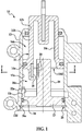
Figure 1 is a cross sectional view of an actuator having a piston reciprocally enclosed within a hollow interior of a housing to define first and second expandable chambers, where a magnet is supported by the piston and a sensor is supported by the housing within the hollow interior to sense a position of the piston along a path of travel within the housing; -
Figure 2 is a cross sectional view of the actuator taken as shown inFigure 1 illustrating the relationship of the magnet with respect to the sensor within a longitudinally extending aperture formed in the piston; -
Figure 3 is a cross sectional view of the actuator taken as shown inFigure 2 ; -
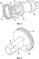
Figure 4 is a perspective view of the piston and a plug supporting the position sensor; -
Figure 5 is a perspective view of the plug supporting the position sensor and illustrating a clocking locator projection to orient the sensor with respect to the piston during assembly; -
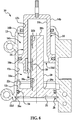
Figure 6 is a cross sectional view of the actuator with a plurality of sensors for sensing multiple positions of the piston along the path of travel within the housing. - Referring now to
Figures 1-5 , anactuator 10 can include ahousing 12 having ahollow interior 12a for enclosing apiston 14 having ahead 14a and arod 14b. Thepiston 14 can be located within thehousing 12 for reciprocation between first and second end limits of travel. Thepiston 14 separates thehousing 12 into first and secondexpandable 16b. Thefluid chambers 16ahousing 12 can have a rod-end opening 12b at one end and a head-end opening 12c at an opposite end. Thepiston 14 can have a longitudinally extendingaperture 14c formed therein with anopen end 14d facing the head-end opening 12c of thehousing 12. Amagnet 18 can be supported by thepiston 14 adjacent to theopen end 14d of the longitudinally extendingaperture 14c in thepiston 14. Aposition sensor 20 can be supported by thehousing 12 within the longitudinally extendingaperture 14c in thepiston 14 adjacent to themagnet 18 for sensing a position of thepiston 14 along a path of travel within thehousing 12. As illustrated inFigure 1 , thesensor 20 senses thepiston 14 in a position between the first and second end limits of travel within thehousing 12. It should be recognized that the sensed position can be at any location along the path of travel, including the end limits of travel. - A
plug 22 can be provided for closing the head-end opening 12c of thehousing 12. The plug can support theposition sensor 20 within thehollow interior 12a of thehousing 12 and within the longitudinally extendingaperture 14c in thepiston 14 adjacent to themagnet 20 as thepiston 14 moves between the first and second end limits of movement within thehousing 12. As best seen inFigure 5 , aclocking locator 22a can be provided on theplug 22 to align thesensor 20 with themagnet 18 supported by thepiston 14 during assembly. As best seen inFigures 1 and3-5 , aseal 24 can be supported by theplug 22 for sealing engagement with the head-end opening 12c at the end of thehousing 12 opposite from the rod-end opening 12b. As best seen inFigures 1 ,3 and4 , aretainer 26 can be provided for maintaining theplug 22 in an assembled relationship with respect to thehousing 12. Theretainer 26 can include a c-shaped retaining clip 26a engageable within agroove 12d formed in thehousing 12 adjacent to the head-end opening 12c of thehousing 12. - A
sensor 20 is disclosed for determining a position of anactuator 10. Theactuator 10 can include anelongate housing 12 having ahollow interior 12a formed therein with an opening 12b, 12c at each end. Apiston 14 can be defined by ahead 14a and arod 14b. Thepiston 14 can be located within thehousing 12 for reciprocal movement between first and second end limits of travel. Therod 14b of thepiston 14 can extend through a rod-end opening 12b at one end of thehousing 12. Thepiston 14 can have a longitudinally extendingaperture 14c formed therein with anopen end 14d facing a head-end opening 12c opposite from the rod-end opening 12b of thehousing 12. Amagnet 18 can be supported by thepiston 14 adjacent to theopen end 14d of the longitudinally extendingaperture 14c in thepiston 14. Aposition sensor 20 can be supported by thehousing 12 within the longitudinally extendingaperture 14c in thepiston 14. - The
sensor 20 can be mounted separate from an end cap orplug 22, or can be integrated into the end cap orplug 22. Theplug 22 can be connected to thehousing 12 for closing the head-end opening 12c opposite from the rod-end opening 12b of thehousing 12. Theplug 22 can support theposition sensor 20 within thehollow interior 12a of thehousing 12 and within the longitudinally extendingaperture 14c in thepiston 14 adjacent to themagnet 18 as thepiston 14 moves between the first and second end limits of movement within thehousing 12. A clockinglocator 22a can be provided on theplug 22 to align thesensor 20 with themagnet 18 supported by thepiston 14 during assembly to thehousing 12. Aseal 24 can be supported by theplug 22 for sealing engagement with the head-end opening 12c of thehousing 12 opposite from the rod-end opening 12b of thehousing 12. Aretainer 26 can be provided for maintaining theplug 22 in an assembled relationship with respect to thehousing 12. By way of example and not limitation, theretainer 26 can include a c-shaped retaining clip 26a engageable within agroove 12d formed in thehousing 12 adjacent to the head-end opening 12c of thehousing 12 opposite from the rod-end opening 12b of thehousing 12. - It should be recognized that
additional sensors 20 can be mounted on an internally extendingstub 28, if sensing of multiple positions of thepiston 14 within thehousing 12 is desired. By way of example and not limitation, as best seen inFigure 6 , asensor 20a can be position adjacent abase 28a of thestub 28 to sense thepiston 14 in a fully retracted position within thehousing 12. By way of example and not limitation, asensor 20b can be located at anouter end 28b of thestub 28 to sense thepiston 14 in a fully extended position with respect to thehousing 12. These positions for thesensor 20 can be used individually or in any combination. It should be recognized thatadditional sensors 20 can be mounted between the first and second end limits of travel to sense multiple positions along the path of travel. The sensors can be aligned with one another along thestub 28 for activation by asingle magnet 18 as illustrated inFigure 6 . If desired, the sensors can be angularly offset with respect to one another and can be activated by a single annular magnet supported by the piston, or by separate magnets supported by the piston, either in an aligned relationship with respect to one another in a single plane or longitudinally spaced with respect to one another. The magnet ormagnets 18 can be injection molded within aplastic piston 14. The sensor orsensors 20 can be injection molded into aplastic stub 28, which can be formed integrally as part of aplug 22 if desired. It should be recognized that the internal position of the sensor orsensors sensors sensors actuator 10. It should be recognized that the disclosed configuration allows a decrease in the an air gap between the position sensor orsensors magnet 18 triggering the position sensor orsensors piston bore 12a andmagnet 28 to reduce a risk of seal failure due to magnetic contamination. - While the invention has been described in connection with what is presently considered to be the most practical and preferred embodiment, it is to be understood that the invention is not to be limited to the disclosed embodiments but, on the contrary, is intended to cover various modifications and equivalent arrangements included within the scope of the appended claims.
Claims (6)
- Actuator (10) comprising:a housing (12) having a hollow interior (12a);a piston (14) having a head (14a) and a rod (14b), the piston (14) located within the hollow interior (12a) of the housing (12) for reciprocation between first and second end limits of travel within the housing (12), and separating the housing (12) into first and second expandable fluid chambers (16a, 16b), the housing (12) having a rod-end opening (12b) at one end and a head-end opening (12c) at an opposite end, the piston (14) having a longitudinally extending aperture (14c) formed therein with an open end (14d) facing the head-end opening (12c) of the housing (12);a magnet (18) supported by the piston (14) adjacent to the open end (14d) of the longitudinally extending aperture (14c) in the piston (14); anda position sensor (20) adjacent to the magnet (18);a plug (22) for closing the head-end opening (12c) of the housing (12), the plug (22) supporting the position sensor (20) within the hollow interior (12a) of the housing (12) and within the longitudinally extending aperture (14c) in the piston (14), adjacent to the magnet (18) as the piston (14) moves between the first and the second end limits of travel within the housing (12);characterized in that the actuator (10) further comprises a clocking locator (22a) on the plug (22) to align the sensor (20) with the magnet (18) during assembly.
- Actuator (10) according to claim 1, the plug (22) being connected to the housing (12).
- 4- Actuator (10) according to one of the preceding claims further comprising a seal (24) supported by the plug (22) for sealing engagement with the head-end opening (12c) of the housing (12).
- Actuator (10) according to one of the preceding claims further comprising a retainer (26) for maintaining the plug (22) in an assembled relationship with respect to the housing (12).
- Actuator (10) according to claim 4 further comprising a c-shaped retaining clip (26a) engageable within a groove (12d) formed in the housing (12) adjacent to the head-end opening (12c) of the housing (12).
- Actuator (10) according to one of the preceding claims, said position sensor (20) being a sensor for sensing a position of the piston (14) along a path of travel within the housing (12).
Applications Claiming Priority (2)
| Application Number | Priority Date | Filing Date | Title |
|---|---|---|---|
| US201261673950P | 2012-07-20 | 2012-07-20 | |
| PCT/US2013/049666 WO2014014702A1 (en) | 2012-07-20 | 2013-07-09 | Internal position sensor |
Publications (3)
| Publication Number | Publication Date |
|---|---|
| EP2875242A1 EP2875242A1 (en) | 2015-05-27 |
| EP2875242A4 EP2875242A4 (en) | 2016-03-30 |
| EP2875242B1 true EP2875242B1 (en) | 2018-03-21 |
Family
ID=49949176
Family Applications (1)
| Application Number | Title | Priority Date | Filing Date |
|---|---|---|---|
| EP13820073.8A Ceased EP2875242B1 (en) | 2012-07-20 | 2013-07-09 | Actuator with internal position sensor |
Country Status (6)
| Country | Link |
|---|---|
| US (1) | US9945402B2 (en) |
| EP (1) | EP2875242B1 (en) |
| JP (1) | JP6153610B2 (en) |
| KR (1) | KR20150036430A (en) |
| CN (1) | CN104395616B (en) |
| WO (1) | WO2014014702A1 (en) |
Families Citing this family (4)
| Publication number | Priority date | Publication date | Assignee | Title |
|---|---|---|---|---|
| JP6410342B2 (en) * | 2014-06-04 | 2018-10-24 | パスカルエンジニアリング株式会社 | Fluid pressure cylinder and clamping device |
| CN106523462B (en) * | 2016-12-30 | 2018-02-13 | 北京强度环境研究所 | A kind of high precision displacement control cylinder device and its control method |
| PT3428461T (en) * | 2017-07-14 | 2021-04-27 | Hydraulique Production Systems | Hydraulic cylinder and installation using at least one such hydraulic cylinder |
| CN117693453A (en) * | 2021-08-11 | 2024-03-12 | 华为技术有限公司 | Hydraulic braking devices, stroke sensors and vehicles |
Family Cites Families (17)
| Publication number | Priority date | Publication date | Assignee | Title |
|---|---|---|---|---|
| DE1960181U (en) | 1967-02-14 | 1967-05-11 | Ludwig Rexroth | HYDRAULIC OR PNEUMATIC WORK CYLINDER. |
| US3643551A (en) | 1970-08-07 | 1972-02-22 | Allis Chalmers Mfg Co | Hydraulic cylinder |
| JPH0630791Y2 (en) | 1988-11-28 | 1994-08-17 | 鹿島建設株式会社 | Hydraulic jack |
| US5150049A (en) | 1991-06-24 | 1992-09-22 | Schuetz Tool & Die, Inc. | Magnetostrictive linear displacement transducer with temperature compensation |
| JPH0755409A (en) | 1993-08-06 | 1995-03-03 | Shin Caterpillar Mitsubishi Ltd | Displacement sensor |
| JPH1037912A (en) | 1996-07-24 | 1998-02-13 | Koganei Corp | Fluid pressure actuator |
| US6020569A (en) * | 1998-04-17 | 2000-02-01 | Dimitrios G. Cecil | Welding system with a real-time weld quality detection sensor |
| JP3734237B2 (en) | 1998-09-10 | 2006-01-11 | カヤバ工業株式会社 | Telescopic position detection structure |
| JP3280345B2 (en) | 1999-05-19 | 2002-05-13 | 株式会社南武 | Cylinder device with stroke end detection function |
| JP2001090714A (en) | 1999-09-21 | 2001-04-03 | Taiyo Ltd | Position detector device for hydraulic cylinder |
| JP2004085578A (en) | 2003-09-26 | 2004-03-18 | S G:Kk | Position detection device |
| US7059238B2 (en) * | 2003-10-17 | 2006-06-13 | Clark Equipment Company | Method and apparatus for stroke position sensor for hydraulic cylinder |
| DE202005006795U1 (en) * | 2005-04-22 | 2005-07-21 | Festo Ag & Co. | Drive unit has position regulator as component part of regulating cartridge which is provided for positioning of drive piston and has electronic regulator and valve unit |
| JP2007333122A (en) * | 2006-06-16 | 2007-12-27 | Kayaba Ind Co Ltd | Hydraulic cylinder |
| JP2008087919A (en) * | 2006-10-02 | 2008-04-17 | Toshiba Elevator Co Ltd | Passenger conveyor |
| US7780560B2 (en) * | 2006-10-27 | 2010-08-24 | Veyance Technologies, Inc. | Power transmission belt |
| FR2911956B1 (en) * | 2007-01-29 | 2009-05-08 | Hispano Suiza Sa | DEVICE FOR MEASURING THE POSITION OF A PISTON IN A CYLINDER, A SET OF A CYLINDER, A PISTON AND A SUCH DEVICE AND AN AIRCRAFT ENGINE COMPRISING SUCH AN ASSEMBLY |
-
2013
- 2013-07-09 JP JP2015523121A patent/JP6153610B2/en not_active Expired - Fee Related
- 2013-07-09 US US14/413,245 patent/US9945402B2/en not_active Expired - Fee Related
- 2013-07-09 CN CN201380034400.8A patent/CN104395616B/en not_active Expired - Fee Related
- 2013-07-09 WO PCT/US2013/049666 patent/WO2014014702A1/en not_active Ceased
- 2013-07-09 EP EP13820073.8A patent/EP2875242B1/en not_active Ceased
- 2013-07-09 KR KR20157003235A patent/KR20150036430A/en not_active Ceased
Non-Patent Citations (1)
| Title |
|---|
| None * |
Also Published As
| Publication number | Publication date |
|---|---|
| CN104395616B (en) | 2016-08-17 |
| CN104395616A (en) | 2015-03-04 |
| KR20150036430A (en) | 2015-04-07 |
| EP2875242A4 (en) | 2016-03-30 |
| EP2875242A1 (en) | 2015-05-27 |
| JP2015522777A (en) | 2015-08-06 |
| WO2014014702A1 (en) | 2014-01-23 |
| US9945402B2 (en) | 2018-04-17 |
| JP6153610B2 (en) | 2017-06-28 |
| US20150167703A1 (en) | 2015-06-18 |
Similar Documents
| Publication | Publication Date | Title |
|---|---|---|
| US9945402B2 (en) | Internal position sensor | |
| US8746422B2 (en) | Combined deceleration and acceleration device | |
| US7963208B2 (en) | Mounting mechanism for a position-detecting sensor | |
| US20060197389A1 (en) | Actuator with position detecting mechanism | |
| EP2474014B1 (en) | Adjustable magnetic target | |
| US9221422B2 (en) | Locking mechanism for pedestrian hood lifters | |
| US9512860B2 (en) | Fluid pressure cylinder | |
| WO2012039293A1 (en) | Linear actuator | |
| EP3770446B1 (en) | Fluid pressure cylinder | |
| JP6407557B2 (en) | Control valve device | |
| JP6238962B2 (en) | Improvements in shock absorbers | |
| EP2143115B1 (en) | Armature and solenoid assembly | |
| US20160273609A1 (en) | Use of inductive sensing to control decoupler position and switchable mount performance | |
| EP3304004B1 (en) | An apparatus for sensing the position of an actuator assembly of a locking gearset | |
| US20160115975A1 (en) | Piston-cylinder unit | |
| JP6540285B2 (en) | Stroke sensor | |
| ES2287265T3 (en) | IMPACT SENSORS WITH A SHEET SWITCH. | |
| TW201804090A (en) | Fluid pressure cylinder device provided with stroke end detecting function | |
| CN108917671B (en) | Stroke position detection assembly of driver | |
| KR100212661B1 (en) | Piston Position Detection Device of Linear Compressor | |
| KR200468974Y1 (en) | Assembling structure of an end cover of a rodless cylinder | |
| JPH0647124Y2 (en) | Switch lead wire extraction mechanism in rodless cylinder | |
| JPH0752566Y2 (en) | Position detection device for moving member in fluid pressure equipment | |
| JP2008019981A (en) | shock absorber | |
| JP2008020378A (en) | Acceleration sensor |
Legal Events
| Date | Code | Title | Description |
|---|---|---|---|
| PUAI | Public reference made under article 153(3) epc to a published international application that has entered the european phase |
Free format text: ORIGINAL CODE: 0009012 |
|
| 17P | Request for examination filed |
Effective date: 20150204 |
|
| AK | Designated contracting states |
Kind code of ref document: A1 Designated state(s): AL AT BE BG CH CY CZ DE DK EE ES FI FR GB GR HR HU IE IS IT LI LT LU LV MC MK MT NL NO PL PT RO RS SE SI SK SM TR |
|
| AX | Request for extension of the european patent |
Extension state: BA ME |
|
| DAX | Request for extension of the european patent (deleted) | ||
| RA4 | Supplementary search report drawn up and despatched (corrected) |
Effective date: 20160225 |
|
| RIC1 | Information provided on ipc code assigned before grant |
Ipc: F15B 15/28 20060101AFI20160219BHEP Ipc: F15B 15/14 20060101ALI20160219BHEP |
|
| GRAP | Despatch of communication of intention to grant a patent |
Free format text: ORIGINAL CODE: EPIDOSNIGR1 |
|
| INTG | Intention to grant announced |
Effective date: 20171004 |
|
| GRAS | Grant fee paid |
Free format text: ORIGINAL CODE: EPIDOSNIGR3 |
|
| GRAA | (expected) grant |
Free format text: ORIGINAL CODE: 0009210 |
|
| RAP1 | Party data changed (applicant data changed or rights of an application transferred) |
Owner name: BORGWARNER INC. |
|
| RBV | Designated contracting states (corrected) |
Designated state(s): DE |
|
| AK | Designated contracting states |
Kind code of ref document: B1 Designated state(s): DE |
|
| REG | Reference to a national code |
Ref country code: DE Ref legal event code: R096 Ref document number: 602013034810 Country of ref document: DE |
|
| PGFP | Annual fee paid to national office [announced via postgrant information from national office to epo] |
Ref country code: DE Payment date: 20180618 Year of fee payment: 6 |
|
| REG | Reference to a national code |
Ref country code: DE Ref legal event code: R097 Ref document number: 602013034810 Country of ref document: DE |
|
| PLBE | No opposition filed within time limit |
Free format text: ORIGINAL CODE: 0009261 |
|
| STAA | Information on the status of an ep patent application or granted ep patent |
Free format text: STATUS: NO OPPOSITION FILED WITHIN TIME LIMIT |
|
| 26N | No opposition filed |
Effective date: 20190102 |
|
| REG | Reference to a national code |
Ref country code: DE Ref legal event code: R119 Ref document number: 602013034810 Country of ref document: DE |
|
| PG25 | Lapsed in a contracting state [announced via postgrant information from national office to epo] |
Ref country code: DE Free format text: LAPSE BECAUSE OF NON-PAYMENT OF DUE FEES Effective date: 20200201 |