EP2874791B2 - Composite waste and water transport elements and methods of manufacture for use on aircraft - Google Patents
Composite waste and water transport elements and methods of manufacture for use on aircraft Download PDFInfo
- Publication number
- EP2874791B2 EP2874791B2 EP13780427.4A EP13780427A EP2874791B2 EP 2874791 B2 EP2874791 B2 EP 2874791B2 EP 13780427 A EP13780427 A EP 13780427A EP 2874791 B2 EP2874791 B2 EP 2874791B2
- Authority
- EP
- European Patent Office
- Prior art keywords
- tube
- tubes
- composite
- combination
- model
- Prior art date
- Legal status (The legal status is an assumption and is not a legal conclusion. Google has not performed a legal analysis and makes no representation as to the accuracy of the status listed.)
- Active
Links
- 238000000034 method Methods 0.000 title claims description 30
- XLYOFNOQVPJJNP-UHFFFAOYSA-N water Substances O XLYOFNOQVPJJNP-UHFFFAOYSA-N 0.000 title claims description 28
- 238000004519 manufacturing process Methods 0.000 title claims description 22
- 239000010786 composite waste Substances 0.000 title description 2
- 239000002131 composite material Substances 0.000 claims description 31
- 239000000463 material Substances 0.000 claims description 31
- 239000002699 waste material Substances 0.000 claims description 27
- 239000000835 fiber Substances 0.000 claims description 18
- 229920001187 thermosetting polymer Polymers 0.000 claims description 9
- 229920001169 thermoplastic Polymers 0.000 claims description 7
- 239000004416 thermosoftening plastic Substances 0.000 claims description 7
- 229910052751 metal Inorganic materials 0.000 claims description 5
- 239000002184 metal Substances 0.000 claims description 5
- 238000010146 3D printing Methods 0.000 claims description 4
- 229920000491 Polyphenylsulfone Polymers 0.000 claims description 4
- 229920000049 Carbon (fiber) Polymers 0.000 claims description 3
- 239000004593 Epoxy Substances 0.000 claims description 3
- 239000002033 PVDF binder Substances 0.000 claims description 3
- 239000004696 Poly ether ether ketone Substances 0.000 claims description 3
- 229920002873 Polyethylenimine Polymers 0.000 claims description 3
- 239000004734 Polyphenylene sulfide Substances 0.000 claims description 3
- 239000004917 carbon fiber Substances 0.000 claims description 3
- 238000005516 engineering process Methods 0.000 claims description 3
- VNWKTOKETHGBQD-UHFFFAOYSA-N methane Chemical compound C VNWKTOKETHGBQD-UHFFFAOYSA-N 0.000 claims description 3
- 229920001652 poly(etherketoneketone) Polymers 0.000 claims description 3
- 229920002530 polyetherether ketone Polymers 0.000 claims description 3
- 229920000069 polyphenylene sulfide Polymers 0.000 claims description 3
- 229920002981 polyvinylidene fluoride Polymers 0.000 claims description 3
- 229920000271 Kevlar® Polymers 0.000 claims description 2
- 229920000784 Nomex Polymers 0.000 claims description 2
- 239000003929 acidic solution Substances 0.000 claims description 2
- 239000011152 fibreglass Substances 0.000 claims description 2
- 239000004761 kevlar Substances 0.000 claims description 2
- 239000004763 nomex Substances 0.000 claims description 2
- 229920001567 vinyl ester resin Polymers 0.000 claims description 2
- 239000002657 fibrous material Substances 0.000 claims 3
- 238000005452 bending Methods 0.000 claims 1
- 238000007598 dipping method Methods 0.000 claims 1
- 239000011162 core material Substances 0.000 description 14
- 239000010935 stainless steel Substances 0.000 description 14
- RTAQQCXQSZGOHL-UHFFFAOYSA-N Titanium Chemical compound [Ti] RTAQQCXQSZGOHL-UHFFFAOYSA-N 0.000 description 13
- 239000010936 titanium Substances 0.000 description 13
- 229910052719 titanium Inorganic materials 0.000 description 13
- 229920005989 resin Polymers 0.000 description 9
- 239000011347 resin Substances 0.000 description 9
- 235000012206 bottled water Nutrition 0.000 description 6
- 239000003651 drinking water Substances 0.000 description 6
- 239000007788 liquid Substances 0.000 description 4
- 230000008018 melting Effects 0.000 description 4
- 238000002844 melting Methods 0.000 description 4
- 239000012783 reinforcing fiber Substances 0.000 description 4
- 238000010438 heat treatment Methods 0.000 description 3
- 239000011159 matrix material Substances 0.000 description 3
- 238000001721 transfer moulding Methods 0.000 description 3
- 239000000853 adhesive Substances 0.000 description 2
- 230000001070 adhesive effect Effects 0.000 description 2
- 230000008014 freezing Effects 0.000 description 2
- 238000007710 freezing Methods 0.000 description 2
- 238000001802 infusion Methods 0.000 description 2
- 238000001746 injection moulding Methods 0.000 description 2
- 150000002739 metals Chemical class 0.000 description 2
- 238000000465 moulding Methods 0.000 description 2
- 239000004033 plastic Substances 0.000 description 2
- 229920003023 plastic Polymers 0.000 description 2
- 239000004417 polycarbonate Substances 0.000 description 2
- 229920000515 polycarbonate Polymers 0.000 description 2
- -1 polyethylene terephthalate Polymers 0.000 description 2
- 229920005644 polyethylene terephthalate glycol copolymer Polymers 0.000 description 2
- 229920001296 polysiloxane Polymers 0.000 description 2
- 239000012781 shape memory material Substances 0.000 description 2
- 239000002195 soluble material Substances 0.000 description 2
- 239000000243 solution Substances 0.000 description 2
- 239000012815 thermoplastic material Substances 0.000 description 2
- 238000007792 addition Methods 0.000 description 1
- 239000000956 alloy Substances 0.000 description 1
- 229910045601 alloy Inorganic materials 0.000 description 1
- 230000009286 beneficial effect Effects 0.000 description 1
- 229910052797 bismuth Inorganic materials 0.000 description 1
- JCXGWMGPZLAOME-UHFFFAOYSA-N bismuth atom Chemical compound [Bi] JCXGWMGPZLAOME-UHFFFAOYSA-N 0.000 description 1
- 239000011248 coating agent Substances 0.000 description 1
- 238000000576 coating method Methods 0.000 description 1
- 230000001351 cycling effect Effects 0.000 description 1
- 238000012217 deletion Methods 0.000 description 1
- 230000037430 deletion Effects 0.000 description 1
- 238000013461 design Methods 0.000 description 1
- 238000004090 dissolution Methods 0.000 description 1
- 238000009730 filament winding Methods 0.000 description 1
- 239000011888 foil Substances 0.000 description 1
- 239000003365 glass fiber Substances 0.000 description 1
- 238000005470 impregnation Methods 0.000 description 1
- 229910052738 indium Inorganic materials 0.000 description 1
- APFVFJFRJDLVQX-UHFFFAOYSA-N indium atom Chemical compound [In] APFVFJFRJDLVQX-UHFFFAOYSA-N 0.000 description 1
- 238000002347 injection Methods 0.000 description 1
- 239000007924 injection Substances 0.000 description 1
- 238000009434 installation Methods 0.000 description 1
- 239000010814 metallic waste Substances 0.000 description 1
- 238000012986 modification Methods 0.000 description 1
- 230000004048 modification Effects 0.000 description 1
- 229920000139 polyethylene terephthalate Polymers 0.000 description 1
- 239000005020 polyethylene terephthalate Substances 0.000 description 1
- 229920001343 polytetrafluoroethylene Polymers 0.000 description 1
- 239000004810 polytetrafluoroethylene Substances 0.000 description 1
- 238000012805 post-processing Methods 0.000 description 1
- 238000007639 printing Methods 0.000 description 1
- 238000000926 separation method Methods 0.000 description 1
- 238000007493 shaping process Methods 0.000 description 1
- 238000010134 structural reaction injection moulding Methods 0.000 description 1
- 239000000126 substance Substances 0.000 description 1
- 229920003002 synthetic resin Polymers 0.000 description 1
- 239000000057 synthetic resin Substances 0.000 description 1
- 229920005992 thermoplastic resin Polymers 0.000 description 1
- 238000009755 vacuum infusion Methods 0.000 description 1
- 238000005406 washing Methods 0.000 description 1
- 238000009736 wetting Methods 0.000 description 1
- 238000004804 winding Methods 0.000 description 1
Images


Classifications
-
- B—PERFORMING OPERATIONS; TRANSPORTING
- B29—WORKING OF PLASTICS; WORKING OF SUBSTANCES IN A PLASTIC STATE IN GENERAL
- B29C—SHAPING OR JOINING OF PLASTICS; SHAPING OF MATERIAL IN A PLASTIC STATE, NOT OTHERWISE PROVIDED FOR; AFTER-TREATMENT OF THE SHAPED PRODUCTS, e.g. REPAIRING
- B29C33/00—Moulds or cores; Details thereof or accessories therefor
- B29C33/44—Moulds or cores; Details thereof or accessories therefor with means for, or specially constructed to facilitate, the removal of articles, e.g. of undercut articles
- B29C33/52—Moulds or cores; Details thereof or accessories therefor with means for, or specially constructed to facilitate, the removal of articles, e.g. of undercut articles soluble or fusible
-
- B—PERFORMING OPERATIONS; TRANSPORTING
- B29—WORKING OF PLASTICS; WORKING OF SUBSTANCES IN A PLASTIC STATE IN GENERAL
- B29C—SHAPING OR JOINING OF PLASTICS; SHAPING OF MATERIAL IN A PLASTIC STATE, NOT OTHERWISE PROVIDED FOR; AFTER-TREATMENT OF THE SHAPED PRODUCTS, e.g. REPAIRING
- B29C64/00—Additive manufacturing, i.e. manufacturing of three-dimensional [3D] objects by additive deposition, additive agglomeration or additive layering, e.g. by 3D printing, stereolithography or selective laser sintering
- B29C64/10—Processes of additive manufacturing
- B29C64/106—Processes of additive manufacturing using only liquids or viscous materials, e.g. depositing a continuous bead of viscous material
-
- B—PERFORMING OPERATIONS; TRANSPORTING
- B29—WORKING OF PLASTICS; WORKING OF SUBSTANCES IN A PLASTIC STATE IN GENERAL
- B29C—SHAPING OR JOINING OF PLASTICS; SHAPING OF MATERIAL IN A PLASTIC STATE, NOT OTHERWISE PROVIDED FOR; AFTER-TREATMENT OF THE SHAPED PRODUCTS, e.g. REPAIRING
- B29C70/00—Shaping composites, i.e. plastics material comprising reinforcements, fillers or preformed parts, e.g. inserts
- B29C70/04—Shaping composites, i.e. plastics material comprising reinforcements, fillers or preformed parts, e.g. inserts comprising reinforcements only, e.g. self-reinforcing plastics
- B29C70/28—Shaping operations therefor
- B29C70/30—Shaping by lay-up, i.e. applying fibres, tape or broadsheet on a mould, former or core; Shaping by spray-up, i.e. spraying of fibres on a mould, former or core
-
- B—PERFORMING OPERATIONS; TRANSPORTING
- B29—WORKING OF PLASTICS; WORKING OF SUBSTANCES IN A PLASTIC STATE IN GENERAL
- B29D—PRODUCING PARTICULAR ARTICLES FROM PLASTICS OR FROM SUBSTANCES IN A PLASTIC STATE
- B29D23/00—Producing tubular articles
-
- F—MECHANICAL ENGINEERING; LIGHTING; HEATING; WEAPONS; BLASTING
- F16—ENGINEERING ELEMENTS AND UNITS; GENERAL MEASURES FOR PRODUCING AND MAINTAINING EFFECTIVE FUNCTIONING OF MACHINES OR INSTALLATIONS; THERMAL INSULATION IN GENERAL
- F16L—PIPES; JOINTS OR FITTINGS FOR PIPES; SUPPORTS FOR PIPES, CABLES OR PROTECTIVE TUBING; MEANS FOR THERMAL INSULATION IN GENERAL
- F16L43/00—Bends; Siphons
- F16L43/008—Bends; Siphons made from plastic material
-
- F—MECHANICAL ENGINEERING; LIGHTING; HEATING; WEAPONS; BLASTING
- F16—ENGINEERING ELEMENTS AND UNITS; GENERAL MEASURES FOR PRODUCING AND MAINTAINING EFFECTIVE FUNCTIONING OF MACHINES OR INSTALLATIONS; THERMAL INSULATION IN GENERAL
- F16L—PIPES; JOINTS OR FITTINGS FOR PIPES; SUPPORTS FOR PIPES, CABLES OR PROTECTIVE TUBING; MEANS FOR THERMAL INSULATION IN GENERAL
- F16L9/00—Rigid pipes
- F16L9/12—Rigid pipes of plastics with or without reinforcement
- F16L9/127—Rigid pipes of plastics with or without reinforcement the walls consisting of a single layer
- F16L9/128—Reinforced pipes
-
- F—MECHANICAL ENGINEERING; LIGHTING; HEATING; WEAPONS; BLASTING
- F16—ENGINEERING ELEMENTS AND UNITS; GENERAL MEASURES FOR PRODUCING AND MAINTAINING EFFECTIVE FUNCTIONING OF MACHINES OR INSTALLATIONS; THERMAL INSULATION IN GENERAL
- F16L—PIPES; JOINTS OR FITTINGS FOR PIPES; SUPPORTS FOR PIPES, CABLES OR PROTECTIVE TUBING; MEANS FOR THERMAL INSULATION IN GENERAL
- F16L9/00—Rigid pipes
- F16L9/12—Rigid pipes of plastics with or without reinforcement
- F16L9/133—Rigid pipes of plastics with or without reinforcement the walls consisting of two layers
-
- B—PERFORMING OPERATIONS; TRANSPORTING
- B29—WORKING OF PLASTICS; WORKING OF SUBSTANCES IN A PLASTIC STATE IN GENERAL
- B29L—INDEXING SCHEME ASSOCIATED WITH SUBCLASS B29C, RELATING TO PARTICULAR ARTICLES
- B29L2023/00—Tubular articles
- B29L2023/004—Bent tubes
-
- B—PERFORMING OPERATIONS; TRANSPORTING
- B33—ADDITIVE MANUFACTURING TECHNOLOGY
- B33Y—ADDITIVE MANUFACTURING, i.e. MANUFACTURING OF THREE-DIMENSIONAL [3-D] OBJECTS BY ADDITIVE DEPOSITION, ADDITIVE AGGLOMERATION OR ADDITIVE LAYERING, e.g. BY 3-D PRINTING, STEREOLITHOGRAPHY OR SELECTIVE LASER SINTERING
- B33Y80/00—Products made by additive manufacturing
-
- Y—GENERAL TAGGING OF NEW TECHNOLOGICAL DEVELOPMENTS; GENERAL TAGGING OF CROSS-SECTIONAL TECHNOLOGIES SPANNING OVER SEVERAL SECTIONS OF THE IPC; TECHNICAL SUBJECTS COVERED BY FORMER USPC CROSS-REFERENCE ART COLLECTIONS [XRACs] AND DIGESTS
- Y10—TECHNICAL SUBJECTS COVERED BY FORMER USPC
- Y10T—TECHNICAL SUBJECTS COVERED BY FORMER US CLASSIFICATION
- Y10T428/00—Stock material or miscellaneous articles
- Y10T428/13—Hollow or container type article [e.g., tube, vase, etc.]
- Y10T428/1352—Polymer or resin containing [i.e., natural or synthetic]
- Y10T428/139—Open-ended, self-supporting conduit, cylinder, or tube-type article
- Y10T428/1393—Multilayer [continuous layer]
Definitions
- Tubes used for the vacuum waste system are primarily straight tubes, which also incorporate bends and wyes (manifolds, pullouts, tees, and so forth).
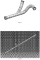
- Figure 1 shows a waste tube which has a wye (pullout) and various bends.
- wyes are welded and fittings (AS1650 style) are swaged or welded to tube ends. In some cases, a beaded end is used per AS5131 in place of the welded fittings.
- Potable water tubes used are primarily straights, wye (pullout, manifold, tee) and bends.
- Figure 2 shows a typical water tube straight with a pullout.
- wyes are welded and fittings (AS1650 style) are brazed or welded to tube ends. Since tube diameters are relatively small, CRES is used in place of titanium for cost savings. Titanium would decrease weight but increase cost.
- WO2009/155491 (Elkhart Brass MFG Co et al) relates to a method of forming a fire fighting monitor includes forming a core in the shape of a nonlinear waterway of a monitor body, applying a composite material over the core, and then curing the composite material to thereby form the fire fighting monitor body.
- FR2942018 (EADS Europ Aeronautic Defense; Composite Atlantic Ltd) relates a tubular part with a complex geometrical shape, the tubular part is made of a composite material including, on the one hand, a core part made of a very high-temperature resin obtained by a 3-D direct-creation method using a very high-temperature thermoplastic resin and, on the other hand, a coating of resin-impregnated fibres.
- the part includes, for example, at least one internal separation of the tube into several conduits that do not communicate with one another.
- the part is suitable for conveying air flows in opposite or separate directions.
- One of the conduits can be a dedicated cable raceway.
- DE4402984 (Daimler Benz Aerospace) relates to a process for producing of tubes with a three-dimensional curved profile involves:(i) production of a low m.pt.
- JP200061959 (Kusaka Rare Metal Kenkyusho) relates to a core that is formed by using an alloy consisting of two or more elements selected, as needed, from bismuth, lead, indium or the like, which can adjust the melting point in accordance with the molding temperature of the hollow molded product.
- Embodiments of the invention described herein thus provide a method for manufacturing waste and water tubes designed for particular use on board an aircraft of other passenger transport vehicle.
- the tubes are manufactured from alternate materials than those that are presently used and are intended to offer cost savings benefits, lower the weight of the system, and provide easier methods to provide tubes having varying curved radii and other shapes that are not typically available with the waste and water tube materials currently in use.
- the current bent water and waste tubes used on an aircraft are bent to standard radii (per manufacturing capabilities).
- the routing of tubes in an aircraft is designed for these limited radii.
- To create a more detailed bend or varying radii of CRES or titanium tubes is either expensive or not possible.
- the present inventers have determined that it would be desirable to manufacture waste and/or water tubes from composite materials.
- the composite tubes developed and described herein are generally not limited to the standard bend radii used for traditional metal waste and water tubes, but instead, they allow for more efficient routing by using variable radius bends, splines, multi-axial bends, corkscrews, and so forth.
- the complex geometry available will also allow for replacement of some hoses with composite tubes.
- thermoplastic materials may be used to form the tube body.
- Such materials may include but are not limited to PVC-type piping, but would use engineered thermoplastic tube materials such as polyethylenimine (PEI), polyphenylene sulfide (PPS), polyphenylsulfone (PPSU), polyether ether ketone (PEEK), polyetherketone ketone (PEKK), polyvinylidene fluoride (PVDF), or any other appropriate thermoplastic material or any combination thereof, along with aerospace style connections (AS1650 or similar).
- thermoset material may be used, such as epoxy, vinyl ester, or any other appropriate thermoset material or any combination thereof.
- An epoxy that may be used is Aerotuf 275-34 TM .
- the configuration is then vacuum bagged, shrink taped, or shrink tubed and cured in an oven or autoclave.
- a shrink tube 16 may then be placed over the tube lay up and shrunk at a temperature below the cure temperature of the pre-impregnated fiber. Once shrunk, the shrink tube 16 itself is sealed with vacuum tape 17 and a vacuum bag 18 at each end, as shown in Figures 7-8 . Thus, the shrink tube becomes the vacuum bag.
- the configuration is then cured in an oven or autoclave. Vacuum could be pulled from one of the vacuum bags 18 applied over the shrink tube onto the mandrel. After cure, the vacuum bag or shrink tube and any other process materials are removed from the part and discarded. The part can be pulled off the mandrel.
- the part and mandrel can be placed in a freezer.
- the mandrel will shrink due to the temperature and the part can be removed.
- the ends of the tube will be trimmed to length. End fittings (similar to AS1653 or other connection type) are bonded to the tube ends.
- An alternative method is to use an inflatable silicone mandrel, apply the liner and composite and insert into a mold cavity.
- the silicone mandrel could be pressurized to press the composite into the tooled surface. This is similar to the SMART tooling described below but would not require the shape memory materials.
- bent tubes and/or tubes with a pullout cannot be made on a hard mandrel (interior tool), as the tooling will be trapped.
- the curvature of the tube makes removal of t the tooling difficult to impossible.
- a further manufacturing method is needed is order to provide the desired shapes, if they are other than straight-which is more often than not the case for water and waste tubes, which must curve with the aircraft architecture.
- One solution for making bent and wye tubes is to use SMART Tooling from Spintech Ventures, LLC or similar process, which uses shape memory materials to create an interior mold which is soft and conformable at high temperatures.
- a bladder is made and placed in a mold. As temperature is increased, the bladder is pressurized with air.
- the composite material can then be laid up on the exterior of the 3D printed tool (a pre-impregnated fiber, a braid, vacuum infusion, or any other option) and cured in an oven or autoclave. Once the composite material is cured, the tool/part is dipped in an acidic solution (low pH) which dissolves the 3D printed soluble material. When removed from the bath, only the composite tube remains. (This process could also be used to make straight tubes.)
- acidic solution low pH
- Non-limiting exemplary materials for such a plate may include but are not limited to be plates formed from polyarylsulphones (PPSU), polycarbonates (PC), titanium, CRES, or any other appropriate material or combinations thereof.
- PPSU polyarylsulphones
- PC polycarbonates
- CRES CRES
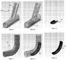
- Figure 9 illustrates a wye/pullout section 20 of a potential tube 22.
- Figure 10 shows a transparent view an impact pad 24 positioned in the wye/pullout tube 22.
- Figure 11 illustrates one example of a potential shape and size for an impact pad 24.
- Figures 12-14 show similar views of a bent tube section 26 having a differently shaped impact pad 28 positioned therein.
- FIG. 15 shows a typical constant radius bend for a tube.
- the incoming line represents the path of a projectile travelling into the bend.
- the impact angle of the projectile in this scenario is about 30°.
- Figure 16 shows a variable radius bend.
- the impact angle of the project in this scenario is reduced to about 18°.
- One reason this is beneficial because composite materials do not have the impact resistance of the titanium or CRES tubes. The lower angle that can be formed, however, will translate to less impact energy being imparted onto the composite tube.
- Typical methods used for waste or water tube manufacturing are generally not able to provide such a variable radius bend without adding a great deal of cost to the manufacturing process.
- thermal conductivity of the composite materials described herein is lower than CRES or titanium, which will make freezing of water in lines less likely. This is an important benefit for aircraft use, in particular, as the proper drainage of aircraft water tubes is of particular concern in order to prevent standing water from freezing and causing the tubes to burst. Further, heating foil or wires can be laid up integrally to the composite tubes described here, or inline heaters may also be installed.
- the composite tubes described herein may also be manufactured with varying cross sections (such as circular or non-circular, including but not limited to oval, D-shaped, C-shaped, curved and flat surface, flat-sided, with a corkscrewed interior or exterior, or any combination thereof) in order to optimize air and waste flow through the system or to accommodate installation in the aircraft.
- varying cross sections could be oval, triangular or rectangular.
- the tubes may even have varying shapes, such as corkscrews or other options.
- internal fins or projections may be provided in the interior of the tubes in order to guide or assist with water and/or waste flow due to the ease of manufacturing options provided by 3D printing.
- this new use of the above-described 3D printing technology in order to form aircraft waste and water tubes is particularly useful in manufacturing tubes having these varied cross-sections and bends, curves, and non-straight alternate shapes.
Description
- Embodiments of the present invention relate generally to composite waste and water transport elements that can be designed having various unique shapes and methods for their manufacture.
- There are generally two types of liquid delivery tubes used on board an aircraft or other aerospace vehicle-vacuum waste tubes and tubes used to carry potable water from a potable water tank to a hand washing station, sink, or other water-using apparatus. Both types of water tubes are typically made out of corrosion resistant steel (CRES) thin walled tubing. For example, current vacuum waste tubes are typically titanium thin walled (0.020" to 0.028") (0.51mm to 0.71cm) tubes of diameters from one to four inches in diameter. In some situations, corrosion resistant steel (CRES) thin walled tubing, which is about 0.020" to 0.035" (0.51mm to 0.89mm) in wall thickness, is used. These tubes are used because these metals meet all aerospace requirements for transport elements (temperature, chemical exposure, structural, impact, and other requirements). Tubes used for the vacuum waste system are primarily straight tubes, which also incorporate bends and wyes (manifolds, pullouts, tees, and so forth).
Figure 1 shows a waste tube which has a wye (pullout) and various bends. Typically, a straight wall titanium tube is bent as required and wyes are welded and fittings (AS1650 style) are swaged or welded to tube ends. In some cases, a beaded end is used per AS5131 in place of the welded fittings. - In the event that a hard object (such as a battery, a cell phone, or other flushable object that is not intended to traverse a vacuum sewer line) is flushed into the vacuum waste system, becoming a projectile, the impact at bends or wyes could break the tube and lead to system failure. Titanium waste tubes are generally used because they are lightweight and handle impact requirements and the vacuum pressure (typically 0 to -11 PSID) cycling of the vacuum waste system. CRES tubes also meet this requirement and while they are less costly, the weight of CRES increases over titanium. CRES (which has a density of about 0.29 lbs/in3 (8.027 g/cm3)) is approximately 60% heavier than titanium (which has a density of about 0.163 lbs/in3 (4.512 g/cm3)).
- The other types of water tubes on an aircraft, potable water tubes (e.g., the tubes that for transporting potable water throughout the aircraft), are typically CRES thin walled (0.020" to 0.035") (0.51mm to 0.89mm) tubes of diameters from about a half inch to about 5 inches in diameter. Titanium may also be used when a lightweight system is required and higher cost is feasible. For areas where complex routing (bends) is required, flexible hoses (for example, AS4468, AS5420 or similar) are used. Water tubes do not have an internal impact requirement but must meet potability requirements (NSF/ANSI Standard 61 or equivalent) and have pressure requirements of 125 PSID proof and 188 PSID burst.
- Potable water tubes used are primarily straights, wye (pullout, manifold, tee) and bends.
Figure 2 shows a typical water tube straight with a pullout. Typically, if a straight tube needs to be bent, wyes are welded and fittings (AS1650 style) are brazed or welded to tube ends. Since tube diameters are relatively small, CRES is used in place of titanium for cost savings. Titanium would decrease weight but increase cost.WO2009/155491 (Elkhart Brass MFG Co et al) relates to a method of forming a fire fighting monitor includes forming a core in the shape of a nonlinear waterway of a monitor body, applying a composite material over the core, and then curing the composite material to thereby form the fire fighting monitor body.FR2942018 DE4402984 (Daimler Benz Aerospace) relates to a process for producing of tubes with a three-dimensional curved profile involves:(i) production of a low m.pt. core with an OD equal to the ID of the pipe; ii) shaping the core, (iii) pushing a thermoplastic sleeve onto the core; (iv) drawing a flexible woven fibre sock over the sleeve; (v) impregnating the fibrous layer with a curable resin; (vi) curing the resin and melting out the core.JP200061959 WO 90/08637 -
EP 2 145 751 A1 discloses a method of manufacturing a hollow body of fiber composite plastic which comprises the following steps: - Providing a preform assembly in the form of a braid, preferably a circular braid, of dry reinforcing fibers on a soluble liquid dispersible core;
- Impregnation of the reinforcing fibers with liquid, curable matrix material in the infusion process according to the vacuum bag principle, wherein the matrix material is sucked into a vacuum film enclosing the preform arrangement in a technically vacuum-tight manner by the action of negative pressure;
- Curing of the matrix material; and
- Removal of the soluble core by dissolution using liquid.
- However, it is desirable to provide waste and water tubes of other materials that are lightweight, that meet the required strength and impact requirements, and that can be manufactured in the desired configurations. In some instances, it is desirable to manufacture tubes with varying diameters, varying lengths, shapes, and curvatures. For example, because the aircraft or other passenger transport vehicle may demand a tortuous waste or water route, the tubes should be designed in such a way that they can have bends or turns easily formed therein. It is also desirable to reduce costs of the tubing, such that their manufacture does not require complicated and expensive tooling in order to manufacture the tubing.
- Embodiments of the invention described herein thus provide a method for manufacturing waste and water tubes designed for particular use on board an aircraft of other passenger transport vehicle. The tubes are manufactured from alternate materials than those that are presently used and are intended to offer cost savings benefits, lower the weight of the system, and provide easier methods to provide tubes having varying curved radii and other shapes that are not typically available with the waste and water tube materials currently in use.
-
-
FIG. 1 shows a side perspective view of a traditional waste tube. -
FIG. 1 shows a side perspective view of a traditional water tube. -
FIGS. 3-8 show steps for manufacturing a composite tube according to one embodiment of the invention. -
Figures 9-10 show a wye/pullout tube with an impact pad positioned therein. -
Figure 11 shows a side perspective view of the impact pad ofFigures 9-10 . -
Figures 12-13 show a bent tube section with an impact pad positioned therein. -
Figure 14 shows a side perspective view of the impact pad ofFigures 12-13 . -
Figure 15 shows an example of a typical constant radius bent tube, and illustrates the angle of impact of a potential projectile. -
Figure 16 shows a variable radius bend of a tube according to methods described herein, and illustrates the lower angle of impact of a potential projectile. - Embodiments of the present invention provide water and waste tubes that may be manufactured from alternate materials. The tubes are designed to meet the same requirements as the titanium, CRES, and hose equivalents but to also save additional weight, allow for more complex geometry, and potentially save cost. The alternate materials from which the waste and water tubes may be made include but are not limited to composite materials such as thermoplastic or thermoset materials with reinforcing fibers.
- The current bent water and waste tubes used on an aircraft are bent to standard radii (per manufacturing capabilities). The routing of tubes in an aircraft is designed for these limited radii. To create a more detailed bend or varying radii of CRES or titanium tubes is either expensive or not possible. The present inventers have determined that it would be desirable to manufacture waste and/or water tubes from composite materials. The composite tubes developed and described herein are generally not limited to the standard bend radii used for traditional metal waste and water tubes, but instead, they allow for more efficient routing by using variable radius bends, splines, multi-axial bends, corkscrews, and so forth. The complex geometry available will also allow for replacement of some hoses with composite tubes.
- Materials. In one embodiment, one or more thermoplastic materials may be used to form the tube body. Such materials may include but are not limited to PVC-type piping, but would use engineered thermoplastic tube materials such as polyethylenimine (PEI), polyphenylene sulfide (PPS), polyphenylsulfone (PPSU), polyether ether ketone (PEEK), polyetherketone ketone (PEKK), polyvinylidene fluoride (PVDF), or any other appropriate thermoplastic material or any combination thereof, along with aerospace style connections (AS1650 or similar). In an alternate embodiment, thermoset material may be used, such as epoxy, vinyl ester, or any other appropriate thermoset material or any combination thereof. One non-limiting example of an epoxy that may be used is Aerotuf 275-34™.
- The thermoplastic and/or thermoset materials may be used with fibers, such as carbon fiber, fiber glass, Kevlar, nomex, or any other appropriate fiber or any combination thereof. The fibers may be continuous or short fibers and may be uni-directional, woven, braided or a combination of these. Depending on the process selected, the fibers could be dry with resin (thermoplastic or thermoset) being introduced at the time of part lay up or pre-impregnated fiber(s) could be used.
- The liner/interior surface of waste tubes may be a film adhesive (such as 3M AF30 or similar) to comply with chemical requirements. Water tubes may have a liner of polyethylene terephthalate (PETG), polytetrafluoroethylene (PTFA) or similar material in order to comply with potable water requirements.
- Tooling/manufacturing process. In one embodiment, straight composite tubes may be manufactured by placing a
liner 10 of 3M AF30™ (a thermosetting film adhesive) or similar material (for waste tubes) or PETG or similar material (for water tubes) on a metal orplastic mandrel 12, as shown inFigures 3-4 . A pre-impregnated fiber 14 is then applied over the liner by filament winding or roll wrapping. In one specific embodiment, the fiber may be a fibeX™ fiber system. An example of amandrel 12 is shown inFigure 3 , and theliner 10 as applied is shown inFigure 4. Figure 5 shows the pre-impregnated fiber 14 would around the liner. The configuration is then vacuum bagged, shrink taped, or shrink tubed and cured in an oven or autoclave. As shown inFigure 6 , ashrink tube 16 may then be placed over the tube lay up and shrunk at a temperature below the cure temperature of the pre-impregnated fiber. Once shrunk, theshrink tube 16 itself is sealed withvacuum tape 17 and avacuum bag 18 at each end, as shown inFigures 7-8 . Thus, the shrink tube becomes the vacuum bag. The configuration is then cured in an oven or autoclave. Vacuum could be pulled from one of thevacuum bags 18 applied over the shrink tube onto the mandrel. After cure, the vacuum bag or shrink tube and any other process materials are removed from the part and discarded. The part can be pulled off the mandrel. If necessary, the part and mandrel can be placed in a freezer. The mandrel will shrink due to the temperature and the part can be removed. After part removal, the ends of the tube will be trimmed to length. End fittings (similar to AS1653 or other connection type) are bonded to the tube ends. - An alternative method is to use an inflatable silicone mandrel, apply the liner and composite and insert into a mold cavity. The silicone mandrel could be pressurized to press the composite into the tooled surface. This is similar to the SMART tooling described below but would not require the shape memory materials.
- Other processes for making tubes could include resin transfer molding (RTM), vacuum assisted resin transfer molding (VARTM), structural reaction injection molding (SRIM), and/or high speed resin transfer molding (HSRTM). These are variations of wetting out reinforcing fiber with resin (thermoplastic or thermoset). A pre-impregnated fiber (woven, uni-direction, braid or a combination of these) may be used to lay up the tube instead of using a resin infusion.
- However, bent tubes and/or tubes with a pullout cannot be made on a hard mandrel (interior tool), as the tooling will be trapped. The curvature of the tube makes removal of t the tooling difficult to impossible. Accordingly, a further manufacturing method is needed is order to provide the desired shapes, if they are other than straight-which is more often than not the case for water and waste tubes, which must curve with the aircraft architecture. One solution for making bent and wye tubes is to use SMART Tooling from Spintech Ventures, LLC or similar process, which uses shape memory materials to create an interior mold which is soft and conformable at high temperatures. A bladder is made and placed in a mold. As temperature is increased, the bladder is pressurized with air. When the bladder softens, it is pushed against the mold and then cooled. Once cooled, it is rigid in the shape of the mold. Composite materials can be laid up and then placed in a final part mold. Heat and air pressure are applied, and as the bladder softens, it pushes the composite against the exterior mold. Once the part is cured, the bladder (still soft at high temperatures) can be removed. This process could also be used to make straight tubes. However, SMART tooling can be expensive.
- Accordingly, a second solution for making bent or wye tubes is to use 3D printing technology. One example of a system that may be used is the Fortus 3D Production System by Stratasys or similar. This system is used to actually first print a 3D model of the interior of the desired tube shape using a soluble material. The material is basic (i.e., it has a high pH). The desired shape can be printed in any diameter, shape, or configuration, depending upon the specifications of the particular water or waste tube to be used and its location for intended use on the aircraft. Post processing of the material is done to achieve a smooth surface of the 3D printed tool. The composite material can then be laid up on the exterior of the 3D printed tool (a pre-impregnated fiber, a braid, vacuum infusion, or any other option) and cured in an oven or autoclave. Once the composite material is cured, the tool/part is dipped in an acidic solution (low pH) which dissolves the 3D printed soluble material. When removed from the bath, only the composite tube remains. (This process could also be used to make straight tubes.) One primary benefit of this method is that there is not a need to create expensive tooling to form a curved or wye tube. By designing the 3D shape in advance, printing the 3D shape and then applying the desired material, any number of options can be designed and/or tested.
- Because most long fiber composites do not have the impact strength of metals, consideration must be taken to meet impact requirements for waste tubes. In addition to variable radius bends as shown in
Figure 16 , impact areas (typically bends and sections where wyes or pullouts enter a straight section) are made with thicker sections of the same material used in the rest of the tube. This increased strength and stiffness may help to minimize any damage from projectiles. In an illustrastive example not falling under the scope of the claims, a plate of impact resistant material is inlaid in the tube (once formed or during tube manufacture) to absorb this impact without damaging the material around it. Non-limiting exemplary materials for such a plate may include but are not limited to be plates formed from polyarylsulphones (PPSU), polycarbonates (PC), titanium, CRES, or any other appropriate material or combinations thereof.Figure 9 illustrates a wye/pullout section 20 of a potential tube 22.Figure 10 shows a transparent view animpact pad 24 positioned in the wye/pullout tube 22.Figure 11 illustrates one example of a potential shape and size for animpact pad 24.Figures 12-14 show similar views of abent tube section 26 having a differently shapedimpact pad 28 positioned therein. - One of the benefits of using composite materials for manufacturing waste and water tubes is that they allow various types of bends and radii, providing more design flexibility than the traditional current tubes that are available. They are also easier to manufacture, and provide the option of varying radii and more curvatures. These types of bends could also be used to lower the angle of impact (larger entry radii), thus reducing the impact energy. For example,
Figure 15 shows a typical constant radius bend for a tube. The incoming line represents the path of a projectile travelling into the bend. The impact angle of the projectile in this scenario is about 30°.Figure 16 shows a variable radius bend. The impact angle of the project in this scenario is reduced to about 18°. One reason this is beneficial because composite materials do not have the impact resistance of the titanium or CRES tubes. The lower angle that can be formed, however, will translate to less impact energy being imparted onto the composite tube. Typical methods used for waste or water tube manufacturing are generally not able to provide such a variable radius bend without adding a great deal of cost to the manufacturing process. - Additionally, the thermal conductivity of the composite materials described herein is lower than CRES or titanium, which will make freezing of water in lines less likely. This is an important benefit for aircraft use, in particular, as the proper drainage of aircraft water tubes is of particular concern in order to prevent standing water from freezing and causing the tubes to burst. Further, heating foil or wires can be laid up integrally to the composite tubes described here, or inline heaters may also be installed.
- The composite tubes described herein may also be manufactured with varying cross sections (such as circular or non-circular, including but not limited to oval, D-shaped, C-shaped, curved and flat surface, flat-sided, with a corkscrewed interior or exterior, or any combination thereof) in order to optimize air and waste flow through the system or to accommodate installation in the aircraft. For example, potential cross sections could be oval, triangular or rectangular. The tubes may even have varying shapes, such as corkscrews or other options. For example, internal fins or projections may be provided in the interior of the tubes in order to guide or assist with water and/or waste flow due to the ease of manufacturing options provided by 3D printing. In fact, this new use of the above-described 3D printing technology in order to form aircraft waste and water tubes is particularly useful in manufacturing tubes having these varied cross-sections and bends, curves, and non-straight alternate shapes.
- Changes and modifications, additions and deletions may be made to the structures and methods recited above and shown in the drawings without departing from the scope of the invention as defined in the claims.
Claims (9)
- A method of manufacturing a waste or water composite tube (20, 26) for use on board an aircraft or other passenger transport vehicle, the tube (20, 26) comprising:a. a tube body comprising a thermoplastic or thermoset material;b. one or more fiber materials incorporated into the tube body;c. wherein the tube has at least one curve or bend;wherein the composite tube comprises an impact area (24, 28) at the at least one curve or bend in the tube wherein a section of the least one curve or bend of the tube comprises a thicker section of material forming the tube so as to strengthen and stiffen the impact area,the method having the steps of:a. providing a 3D model of a desired interior shape of the tube of a soluble basic material using 3D printing technology, the 3D model having at least one feature that could not be manufactured by bending a metal tube;b. applying a composite material to the 3D model;c. curing the composite material;d. dipping the 3D model with composite material in an acidic solution to dissolve the 3D model so that only the composite tube remains.
- The method of claim 1,
wherein the tube has a non-circular cross-section. - The method of claim 2, wherein the cross section comprises an oval, D-shaped, C-shaped, curved and flat surface, flat-sided, corkscrewed cross section, or any combination thereof.
- The method of any of the preceding claims, wherein the tube comprises polyethylenimine, polyphenylene sulfide, polyphenylsulfone, polyether ether ketone, polyetherketone ketone, polyvinylidene fluoride, or any combination thereof.
- The method of any of the preceding claims, wherein the tube comprises epoxy, vinyl ester, or any combination thereof.
- The method of any of the preceding claims, wherein the fiber materials comprise carbon fiber, fiber glass, Kevlar, nomex, or any combination thereof.
- The method of any of the preceding claims, wherein the fiber materials are continuous fibers, short fibers, uni-directional, woven, braided, or any combination thereof.
- The method of any of the preceding claims, wherein the feature comprises a variable radius bend.
- The method of any of the preceding claims, further comprising adding an impact plate to a location along the tube interior.
Applications Claiming Priority (2)
| Application Number | Priority Date | Filing Date | Title |
|---|---|---|---|
| US201261673863P | 2012-07-20 | 2012-07-20 | |
| PCT/US2013/051181 WO2014028169A2 (en) | 2012-07-20 | 2013-07-19 | Composite waste and water transport elements and methods of manufacture for use on aircraft |
Publications (3)
| Publication Number | Publication Date |
|---|---|
| EP2874791A2 EP2874791A2 (en) | 2015-05-27 |
| EP2874791B1 EP2874791B1 (en) | 2018-12-19 |
| EP2874791B2 true EP2874791B2 (en) | 2022-08-17 |
Family
ID=49484414
Family Applications (1)
| Application Number | Title | Priority Date | Filing Date |
|---|---|---|---|
| EP13780427.4A Active EP2874791B2 (en) | 2012-07-20 | 2013-07-19 | Composite waste and water transport elements and methods of manufacture for use on aircraft |
Country Status (5)
| Country | Link |
|---|---|
| US (1) | US9458955B2 (en) |
| EP (1) | EP2874791B2 (en) |
| JP (1) | JP2015534006A (en) |
| CA (1) | CA2879869C (en) |
| WO (1) | WO2014028169A2 (en) |
Families Citing this family (66)
| Publication number | Priority date | Publication date | Assignee | Title |
|---|---|---|---|---|
| US9511543B2 (en) | 2012-08-29 | 2016-12-06 | Cc3D Llc | Method and apparatus for continuous composite three-dimensional printing |
| CN105102213B (en) * | 2012-11-09 | 2018-08-10 | 帝斯曼知识产权资产管理有限公司 | The system and method that three-dimensional article is prepared by flexible composite |
| BR112016025505A2 (en) * | 2014-05-01 | 2017-08-15 | Kavanaugh Gerry | multilayer composite waste pipe |
| US9857002B2 (en) * | 2014-05-09 | 2018-01-02 | United Technologies Corporation | Fluid couplings and methods for additive manufacturing thereof |
| MX2017000061A (en) | 2014-07-02 | 2017-05-23 | Divergent Tech Inc | Systems and methods for fabricating joint members. |
| US10960929B2 (en) | 2014-07-02 | 2021-03-30 | Divergent Technologies, Inc. | Systems and methods for vehicle subassembly and fabrication |
| US9605783B2 (en) * | 2014-10-27 | 2017-03-28 | The Boeing Company | Rotary fluid coupling |
| EP3086011B1 (en) | 2015-04-21 | 2019-07-31 | Airbus Operations GmbH | Double-walled pipe with integrated heating capability for an aircraft or spacecraft |
| EP3341179A4 (en) * | 2015-08-25 | 2019-10-30 | University of South Carolina | Integrated robotic 3d printing system for printing of fiber reinforced parts |
| EP3344522A4 (en) * | 2015-08-31 | 2019-05-15 | Divergent Technologies Inc. | Systems and methods for vehicle subassembly and fabrication |
| US10543640B2 (en) | 2016-09-06 | 2020-01-28 | Continuous Composites Inc. | Additive manufacturing system having in-head fiber teasing |
| US10901386B2 (en) | 2016-09-06 | 2021-01-26 | Continuous Composites Inc. | Systems and methods for controlling additive manufacturing |
| US10759113B2 (en) | 2016-09-06 | 2020-09-01 | Continuous Composites Inc. | Additive manufacturing system having trailing cure mechanism |
| US10625467B2 (en) | 2016-09-06 | 2020-04-21 | Continuous Composites Inc. | Additive manufacturing system having adjustable curing |
| US20180065317A1 (en) | 2016-09-06 | 2018-03-08 | Cc3D Llc | Additive manufacturing system having in-situ fiber splicing |
| US11091847B2 (en) | 2016-10-28 | 2021-08-17 | Unison Industries Llc | Method of manufacturing aircraft engine parts utilizing reusable and reconfigurable smart memory polymer mandrel |
| US10766595B2 (en) | 2016-11-03 | 2020-09-08 | Continuous Composites Inc. | Composite vehicle body |
| US20210094230A9 (en) | 2016-11-04 | 2021-04-01 | Continuous Composites Inc. | System for additive manufacturing |
| US10953598B2 (en) | 2016-11-04 | 2021-03-23 | Continuous Composites Inc. | Additive manufacturing system having vibrating nozzle |
| US10940638B2 (en) | 2017-01-24 | 2021-03-09 | Continuous Composites Inc. | Additive manufacturing system having finish-follower |
| US10040240B1 (en) | 2017-01-24 | 2018-08-07 | Cc3D Llc | Additive manufacturing system having fiber-cutting mechanism |
| US20180229092A1 (en) | 2017-02-13 | 2018-08-16 | Cc3D Llc | Composite sporting equipment |
| US10798783B2 (en) | 2017-02-15 | 2020-10-06 | Continuous Composites Inc. | Additively manufactured composite heater |
| US11117362B2 (en) | 2017-03-29 | 2021-09-14 | Tighitco, Inc. | 3D printed continuous fiber reinforced part |
| US10948108B2 (en) | 2017-05-02 | 2021-03-16 | Unison Industries, Llc | Turbine engine duct |
| US10814569B2 (en) | 2017-06-29 | 2020-10-27 | Continuous Composites Inc. | Method and material for additive manufacturing |
| US10906240B2 (en) | 2017-06-29 | 2021-02-02 | Continuous Composites Inc. | Print head for additive manufacturing system |
| US11091266B2 (en) * | 2017-08-29 | 2021-08-17 | Goodrich Corporation | Conformable tank fabricated using additive manufacturing |
| US11939105B2 (en) | 2017-08-29 | 2024-03-26 | Goodrich Corporation | 3D woven conformable tank |
| US10703481B2 (en) | 2017-08-29 | 2020-07-07 | Goodrich Corporation | Conformable tank with sandwich structure walls |
| US10816138B2 (en) | 2017-09-15 | 2020-10-27 | Goodrich Corporation | Manufacture of a conformable pressure vessel |
| US10319499B1 (en) | 2017-11-30 | 2019-06-11 | Cc3D Llc | System and method for additively manufacturing composite wiring harness |
| US10131088B1 (en) | 2017-12-19 | 2018-11-20 | Cc3D Llc | Additive manufacturing method for discharging interlocking continuous reinforcement |
| US10081129B1 (en) | 2017-12-29 | 2018-09-25 | Cc3D Llc | Additive manufacturing system implementing hardener pre-impregnation |
| US10857729B2 (en) | 2017-12-29 | 2020-12-08 | Continuous Composites Inc. | System and method for additively manufacturing functional elements into existing components |
| US10919222B2 (en) | 2017-12-29 | 2021-02-16 | Continuous Composites Inc. | System and method for additively manufacturing functional elements into existing components |
| US10759114B2 (en) | 2017-12-29 | 2020-09-01 | Continuous Composites Inc. | System and print head for continuously manufacturing composite structure |
| US11167495B2 (en) | 2017-12-29 | 2021-11-09 | Continuous Composites Inc. | System and method for additively manufacturing functional elements into existing components |
| US11207821B2 (en) | 2018-01-26 | 2021-12-28 | General Electric Company | Method of making 3D tube and 3D tube made thereby |
| JP2019130691A (en) * | 2018-01-29 | 2019-08-08 | 旭化成株式会社 | Hollow molding and method for producing the same |
| CN108527807B (en) * | 2018-04-04 | 2020-03-27 | 中国石油大学(北京) | Non-metal flexible pipe and manufacturing method thereof |
| US11161300B2 (en) | 2018-04-11 | 2021-11-02 | Continuous Composites Inc. | System and print head for additive manufacturing system |
| US11110654B2 (en) | 2018-04-12 | 2021-09-07 | Continuous Composites Inc. | System and print head for continuously manufacturing composite structure |
| US11110656B2 (en) | 2018-04-12 | 2021-09-07 | Continuous Composites Inc. | System for continuously manufacturing composite structure |
| EP3563962B1 (en) * | 2018-05-01 | 2021-12-08 | Hamilton Sundstrand Corporation | Duct manufacturing method |
| US11052603B2 (en) | 2018-06-07 | 2021-07-06 | Continuous Composites Inc. | Additive manufacturing system having stowable cutting mechanism |
| EP3837104A4 (en) | 2018-08-13 | 2022-04-27 | University of South Carolina | Systems and methods for printing 3-dimensional objects from thermoplastics |
| US20200086563A1 (en) | 2018-09-13 | 2020-03-19 | Cc3D Llc | System and head for continuously manufacturing composite structure |
| US11235522B2 (en) | 2018-10-04 | 2022-02-01 | Continuous Composites Inc. | System for additively manufacturing composite structures |
| US11511480B2 (en) | 2018-10-26 | 2022-11-29 | Continuous Composites Inc. | System for additive manufacturing |
| US11420390B2 (en) | 2018-11-19 | 2022-08-23 | Continuous Composites Inc. | System for additively manufacturing composite structure |
| US11358331B2 (en) | 2018-11-19 | 2022-06-14 | Continuous Composites Inc. | System and head for continuously manufacturing composite structure |
| US20200238603A1 (en) | 2019-01-25 | 2020-07-30 | Continuous Composites Inc. | System for additively manufacturing composite structure |
| GB201904674D0 (en) * | 2019-04-03 | 2019-05-15 | Wet Holdings Global Ltd | Pipes for carrying water |
| US11668094B2 (en) * | 2019-05-23 | 2023-06-06 | Ronald P. Vitarelli | Multi-directional gutter downspout system, and methods of making and using same |
| US11312083B2 (en) | 2019-05-28 | 2022-04-26 | Continuous Composites Inc. | System for additively manufacturing composite structure |
| US11840022B2 (en) | 2019-12-30 | 2023-12-12 | Continuous Composites Inc. | System and method for additive manufacturing |
| GB202002033D0 (en) * | 2020-02-14 | 2020-04-01 | Agco Do Brasil Solucoes Argicolas Ltda | Composite elbows, agricultural implements having composite elbows, and methods of forming such elbows |
| US11904534B2 (en) | 2020-02-25 | 2024-02-20 | Continuous Composites Inc. | Additive manufacturing system |
| US11926100B2 (en) | 2020-06-23 | 2024-03-12 | Continuous Composites Inc. | Systems and methods for controlling additive manufacturing |
| US11697244B2 (en) | 2020-08-28 | 2023-07-11 | University Of South Carolina | In-line polymerization for customizable composite fiber manufacture in additive manufacturing |
| US11465348B2 (en) | 2020-09-11 | 2022-10-11 | Continuous Composites Inc. | Print head for additive manufacturing system |
| US11926099B2 (en) | 2021-04-27 | 2024-03-12 | Continuous Composites Inc. | Additive manufacturing system |
| CN113757474B (en) * | 2021-08-05 | 2022-10-14 | 岭东核电有限公司 | Special-shaped three-way pipeline and manufacturing method thereof |
| DE102021124575A1 (en) | 2021-09-22 | 2023-03-23 | Sunrise Medical Gmbh | Additive carbon fiber molding process |
| JP7368893B1 (en) | 2022-11-08 | 2023-10-25 | 冨士ダイス株式会社 | Elbow pipe and its manufacturing method |
Citations (26)
| Publication number | Priority date | Publication date | Assignee | Title |
|---|---|---|---|---|
| EP0009496B1 (en) † | 1978-02-23 | 1981-11-25 | INTERATOM Internationale Atomreaktorbau GmbH | Multiple wall angle connection |
| US4461498A (en) † | 1981-12-02 | 1984-07-24 | Victaulic Company Of America | Coupling members for pipeline assemblies |
| EP0313923B1 (en) † | 1987-10-28 | 1993-03-03 | Bayerische Motoren Werke Aktiengesellschaft, Patentabteilung AJ-3 | Method and mould core for producing undercut plastics articles |
| DE4202878A1 (en) † | 1992-02-01 | 1993-08-05 | Alfred Eigen | Hollow metal or reaction-cast resin article mfr. - by casting using residue-free removable core |
| US5262100A (en) † | 1990-07-11 | 1993-11-16 | Advanced Plastics Partnership | Method of core removal from molded products |
| DE19500953C1 (en) † | 1995-01-14 | 1996-07-25 | Esser Werke Gmbh & Co Kg | Arcuate section of tube for fitting in piping for hydraulic or pneumatic conveying of solid materials |
| US5736619A (en) † | 1995-04-21 | 1998-04-07 | Ameron International Corporation | Phenolic resin compositions with improved impact resistance |
| EP0803456B1 (en) † | 1996-04-27 | 1998-10-14 | MASTERFLEX Kunststofftechnik GmbH | Pipebend |
| EP0916464A2 (en) † | 1997-11-12 | 1999-05-19 | Sakura Rubber Co., Ltd. | Method of manufacturing structure by using biodegradable mold |
| DE10012507A1 (en) † | 1999-03-17 | 2000-10-05 | Whitaker Corp | Cover for electrical connector assemblies |
| CN2433493Y (en) † | 2000-06-14 | 2001-06-06 | 曲树蓁 | Wear-resisting bent tube |
| CN1415888A (en) † | 2002-10-04 | 2003-05-07 | 宜兴市宙斯泵业有限公司 | Channel elbow with wearable liner and lining method thereof |
| US6764102B2 (en) † | 2002-03-22 | 2004-07-20 | Smc Kabushiki Kaisha | Tube joint |
| US6794048B2 (en) † | 2000-12-23 | 2004-09-21 | Degussa Ag | Multilayer composite based on polyamide/polyolefin |
| DE102004060192A1 (en) † | 2004-12-14 | 2006-06-29 | Poloplast Gmbh & Co.Kg | Plastic pipe section for pipe systems in drain water domestic plumbing has section of pipe which is impinged by drain water provided with core layer made from sound damping material |
| DE102006025049A1 (en) † | 2006-05-30 | 2007-12-06 | Rehau Ag + Co. | Shaped part for piping systems for the discharge of waste water |
| EP2145751A1 (en) † | 2008-07-18 | 2010-01-20 | Euro-Composites S.A. | Method for producing a hollow body from fibre compound plastic |
| DE102008061837A1 (en) † | 2008-12-15 | 2010-06-17 | Technische Universität Dresden | Internally coated molded part e.g. pipe bend, for conveying concrete in conveyor pipes, has sleeve pipe made of impact-resistant material, and inner coating made of mineral grain mixture and hardened binder that fills cavities in mixture |
| US20110000398A1 (en) † | 2007-07-13 | 2011-01-06 | Advanced Ceramics Manufacturing Llc | Materials and methods for production of aggregate-based tooling |
| US20110041947A1 (en) † | 2009-02-19 | 2011-02-24 | Composite Development Group LLC | Composite Pipe and Method of Manufacture |
| US8043696B2 (en) † | 2004-10-22 | 2011-10-25 | Dow Global Technologies Llc | Microlayer structures and methods |
| DE102010014923A1 (en) † | 2010-04-14 | 2011-12-15 | Christoph Bartsch | Pipework system for conveying mediums, has outer pipe half-shell upper part and outer pipe half-shell lower part, where outer pipe-half shells are made of steel or plastic in composite construction |
| US20110305860A1 (en) † | 2010-06-11 | 2011-12-15 | Ticona Llc | Blow Molded Articles and Process For Making Same |
| US20120132310A1 (en) † | 2009-02-10 | 2012-05-31 | Composite Atlantic Limited | Composite tubular parts with complex shapes |
| WO2012088375A2 (en) † | 2010-12-22 | 2012-06-28 | Ticona Llc | Fiber reinforced shaped articles and process for making same |
| JP2013057377A (en) † | 2011-09-09 | 2013-03-28 | Showa Denko Kenzai Kk | Piping noise-insulation-coating structure |
Family Cites Families (7)
| Publication number | Priority date | Publication date | Assignee | Title |
|---|---|---|---|---|
| DE1012507B (en) | 1951-10-29 | 1957-07-18 | Andre Huet Und Cie Des Surchau | Process for bending and hot forming of hollow bodies |
| CH488546A (en) | 1969-09-09 | 1970-04-15 | Keller Emil | Method and device for the production of pipe bends from plastic |
| SE465259B (en) * | 1989-02-02 | 1991-08-19 | Electrolux Plastcenter Ab | SET AND DEVICE FOR INJECTION |
| DE4402984C2 (en) * | 1994-02-01 | 1996-04-18 | Daimler Benz Aerospace Ag | Process for the production of pipelines |
| JP2000061959A (en) | 1998-08-12 | 2000-02-29 | Kusaka Rare Metal Kenkyusho:Kk | Method for forming hollow molded product and core |
| WO2009155491A2 (en) | 2008-06-20 | 2009-12-23 | Elkhart Brass Manufacturing Company, Inc. | Fire fighting device with waterway |
| US9757876B2 (en) * | 2012-02-27 | 2017-09-12 | Red River College | Method for making an article from a curable material |
-
2013
- 2013-07-19 US US13/945,940 patent/US9458955B2/en active Active
- 2013-07-19 EP EP13780427.4A patent/EP2874791B2/en active Active
- 2013-07-19 WO PCT/US2013/051181 patent/WO2014028169A2/en active Application Filing
- 2013-07-19 JP JP2015523272A patent/JP2015534006A/en active Pending
- 2013-07-19 CA CA2879869A patent/CA2879869C/en active Active
Patent Citations (26)
| Publication number | Priority date | Publication date | Assignee | Title |
|---|---|---|---|---|
| EP0009496B1 (en) † | 1978-02-23 | 1981-11-25 | INTERATOM Internationale Atomreaktorbau GmbH | Multiple wall angle connection |
| US4461498A (en) † | 1981-12-02 | 1984-07-24 | Victaulic Company Of America | Coupling members for pipeline assemblies |
| EP0313923B1 (en) † | 1987-10-28 | 1993-03-03 | Bayerische Motoren Werke Aktiengesellschaft, Patentabteilung AJ-3 | Method and mould core for producing undercut plastics articles |
| US5262100A (en) † | 1990-07-11 | 1993-11-16 | Advanced Plastics Partnership | Method of core removal from molded products |
| DE4202878A1 (en) † | 1992-02-01 | 1993-08-05 | Alfred Eigen | Hollow metal or reaction-cast resin article mfr. - by casting using residue-free removable core |
| DE19500953C1 (en) † | 1995-01-14 | 1996-07-25 | Esser Werke Gmbh & Co Kg | Arcuate section of tube for fitting in piping for hydraulic or pneumatic conveying of solid materials |
| US5736619A (en) † | 1995-04-21 | 1998-04-07 | Ameron International Corporation | Phenolic resin compositions with improved impact resistance |
| EP0803456B1 (en) † | 1996-04-27 | 1998-10-14 | MASTERFLEX Kunststofftechnik GmbH | Pipebend |
| EP0916464A2 (en) † | 1997-11-12 | 1999-05-19 | Sakura Rubber Co., Ltd. | Method of manufacturing structure by using biodegradable mold |
| DE10012507A1 (en) † | 1999-03-17 | 2000-10-05 | Whitaker Corp | Cover for electrical connector assemblies |
| CN2433493Y (en) † | 2000-06-14 | 2001-06-06 | 曲树蓁 | Wear-resisting bent tube |
| US6794048B2 (en) † | 2000-12-23 | 2004-09-21 | Degussa Ag | Multilayer composite based on polyamide/polyolefin |
| US6764102B2 (en) † | 2002-03-22 | 2004-07-20 | Smc Kabushiki Kaisha | Tube joint |
| CN1415888A (en) † | 2002-10-04 | 2003-05-07 | 宜兴市宙斯泵业有限公司 | Channel elbow with wearable liner and lining method thereof |
| US8043696B2 (en) † | 2004-10-22 | 2011-10-25 | Dow Global Technologies Llc | Microlayer structures and methods |
| DE102004060192A1 (en) † | 2004-12-14 | 2006-06-29 | Poloplast Gmbh & Co.Kg | Plastic pipe section for pipe systems in drain water domestic plumbing has section of pipe which is impinged by drain water provided with core layer made from sound damping material |
| DE102006025049A1 (en) † | 2006-05-30 | 2007-12-06 | Rehau Ag + Co. | Shaped part for piping systems for the discharge of waste water |
| US20110000398A1 (en) † | 2007-07-13 | 2011-01-06 | Advanced Ceramics Manufacturing Llc | Materials and methods for production of aggregate-based tooling |
| EP2145751A1 (en) † | 2008-07-18 | 2010-01-20 | Euro-Composites S.A. | Method for producing a hollow body from fibre compound plastic |
| DE102008061837A1 (en) † | 2008-12-15 | 2010-06-17 | Technische Universität Dresden | Internally coated molded part e.g. pipe bend, for conveying concrete in conveyor pipes, has sleeve pipe made of impact-resistant material, and inner coating made of mineral grain mixture and hardened binder that fills cavities in mixture |
| US20120132310A1 (en) † | 2009-02-10 | 2012-05-31 | Composite Atlantic Limited | Composite tubular parts with complex shapes |
| US20110041947A1 (en) † | 2009-02-19 | 2011-02-24 | Composite Development Group LLC | Composite Pipe and Method of Manufacture |
| DE102010014923A1 (en) † | 2010-04-14 | 2011-12-15 | Christoph Bartsch | Pipework system for conveying mediums, has outer pipe half-shell upper part and outer pipe half-shell lower part, where outer pipe-half shells are made of steel or plastic in composite construction |
| US20110305860A1 (en) † | 2010-06-11 | 2011-12-15 | Ticona Llc | Blow Molded Articles and Process For Making Same |
| WO2012088375A2 (en) † | 2010-12-22 | 2012-06-28 | Ticona Llc | Fiber reinforced shaped articles and process for making same |
| JP2013057377A (en) † | 2011-09-09 | 2013-03-28 | Showa Denko Kenzai Kk | Piping noise-insulation-coating structure |
Also Published As
| Publication number | Publication date |
|---|---|
| EP2874791B1 (en) | 2018-12-19 |
| CA2879869A1 (en) | 2014-02-20 |
| WO2014028169A3 (en) | 2014-03-27 |
| US9458955B2 (en) | 2016-10-04 |
| WO2014028169A2 (en) | 2014-02-20 |
| JP2015534006A (en) | 2015-11-26 |
| CA2879869C (en) | 2020-07-14 |
| EP2874791A2 (en) | 2015-05-27 |
| US20140023812A1 (en) | 2014-01-23 |
Similar Documents
| Publication | Publication Date | Title |
|---|---|---|
| EP2874791B2 (en) | Composite waste and water transport elements and methods of manufacture for use on aircraft | |
| US9222605B2 (en) | Ducting for a fluid transfer pipeline for an aircraft or spacecraft, method for producing same and aeronautical structure incorporating same | |
| JP2012530628A5 (en) | ||
| EP2433781A3 (en) | Method and apparatus for fabricating highly contoured composite stiffeners with reduced wrinkling | |
| US20120132310A1 (en) | Composite tubular parts with complex shapes | |
| CN111587178B (en) | Method of manufacturing a wind turbine rotor blade panel with a printed grid structure | |
| JP6457330B2 (en) | Fiber reinforced resin composite tubular structure and method for producing the same | |
| US8047237B2 (en) | Thermosetting or thermoplastic arrangement for manufacturing piping for air conditioning | |
| US7585448B2 (en) | Tube induced deformity elimination process | |
| US10018175B2 (en) | Induction consolidation for wind blade fabrication | |
| KR101509103B1 (en) | Composite pipe, composite roller, composite pipe manufacturing method and composite roller manufacturing method using the composite pipe | |
| CN110513546A (en) | Double modelings or more modeling ribbing spiral winding pipes | |
| EP2061640B1 (en) | Method and assembly for the production of a homogenous composite pipe of unspecified length | |
| CN204196271U (en) | A kind of composite material elbow filament-wound device | |
| JP5918171B2 (en) | FRP fabric, molding material using FRP fabric, and method for manufacturing FRP fabric | |
| CN204554336U (en) | Unidirectional fibre reinforced pipe | |
| CN210484855U (en) | Flexible composite pipe | |
| CN202764227U (en) | Device for producing external corrugated fiber reinforced plastic (FRP) pipe | |
| EP1696530B1 (en) | Impact resistant conduit | |
| JP2007216558A (en) | Fiber-reinforced synthetic resin bobbin | |
| WO2017151603A1 (en) | Methods for fabricating preforms for high performance ultra-long fiber reinforced thermoplastic tubing | |
| US20220185480A1 (en) | Linerless, conformable composite tank structure for aircraft water and waste | |
| CN111457171A (en) | Non-adhesive equidirectionally wound thermoplastic flexible pipe and manufacturing method thereof | |
| CN202930886U (en) | Fiber-reinforced polypropylene composite electrical tube | |
| CN113007460B (en) | Continuous fiber rope reinforced elliptical stirrup joint ring corrugated pipe |
Legal Events
| Date | Code | Title | Description |
|---|---|---|---|
| PUAI | Public reference made under article 153(3) epc to a published international application that has entered the european phase |
Free format text: ORIGINAL CODE: 0009012 |
|
| 17P | Request for examination filed |
Effective date: 20150213 |
|
| AK | Designated contracting states |
Kind code of ref document: A2 Designated state(s): AL AT BE BG CH CY CZ DE DK EE ES FI FR GB GR HR HU IE IS IT LI LT LU LV MC MK MT NL NO PL PT RO RS SE SI SK SM TR |
|
| AX | Request for extension of the european patent |
Extension state: BA ME |
|
| RIN1 | Information on inventor provided before grant (corrected) |
Inventor name: HAMMER, JASON Inventor name: MITTUR, MOHAN |
|
| DAX | Request for extension of the european patent (deleted) | ||
| STAA | Information on the status of an ep patent application or granted ep patent |
Free format text: STATUS: EXAMINATION IS IN PROGRESS |
|
| 17Q | First examination report despatched |
Effective date: 20170124 |
|
| GRAP | Despatch of communication of intention to grant a patent |
Free format text: ORIGINAL CODE: EPIDOSNIGR1 |
|
| STAA | Information on the status of an ep patent application or granted ep patent |
Free format text: STATUS: GRANT OF PATENT IS INTENDED |
|
| INTG | Intention to grant announced |
Effective date: 20180705 |
|
| GRAS | Grant fee paid |
Free format text: ORIGINAL CODE: EPIDOSNIGR3 |
|
| GRAA | (expected) grant |
Free format text: ORIGINAL CODE: 0009210 |
|
| STAA | Information on the status of an ep patent application or granted ep patent |
Free format text: STATUS: THE PATENT HAS BEEN GRANTED |
|
| AK | Designated contracting states |
Kind code of ref document: B1 Designated state(s): AL AT BE BG CH CY CZ DE DK EE ES FI FR GB GR HR HU IE IS IT LI LT LU LV MC MK MT NL NO PL PT RO RS SE SI SK SM TR |
|
| REG | Reference to a national code |
Ref country code: GB Ref legal event code: FG4D |
|
| REG | Reference to a national code |
Ref country code: CH Ref legal event code: EP |
|
| REG | Reference to a national code |
Ref country code: IE Ref legal event code: FG4D |
|
| REG | Reference to a national code |
Ref country code: DE Ref legal event code: R096 Ref document number: 602013048485 Country of ref document: DE |
|
| REG | Reference to a national code |
Ref country code: AT Ref legal event code: REF Ref document number: 1078196 Country of ref document: AT Kind code of ref document: T Effective date: 20190115 |
|
| REG | Reference to a national code |
Ref country code: NL Ref legal event code: MP Effective date: 20181219 |
|
| PG25 | Lapsed in a contracting state [announced via postgrant information from national office to epo] |
Ref country code: FI Free format text: LAPSE BECAUSE OF FAILURE TO SUBMIT A TRANSLATION OF THE DESCRIPTION OR TO PAY THE FEE WITHIN THE PRESCRIBED TIME-LIMIT Effective date: 20181219 Ref country code: BG Free format text: LAPSE BECAUSE OF FAILURE TO SUBMIT A TRANSLATION OF THE DESCRIPTION OR TO PAY THE FEE WITHIN THE PRESCRIBED TIME-LIMIT Effective date: 20190319 Ref country code: LT Free format text: LAPSE BECAUSE OF FAILURE TO SUBMIT A TRANSLATION OF THE DESCRIPTION OR TO PAY THE FEE WITHIN THE PRESCRIBED TIME-LIMIT Effective date: 20181219 Ref country code: NO Free format text: LAPSE BECAUSE OF FAILURE TO SUBMIT A TRANSLATION OF THE DESCRIPTION OR TO PAY THE FEE WITHIN THE PRESCRIBED TIME-LIMIT Effective date: 20190319 Ref country code: HR Free format text: LAPSE BECAUSE OF FAILURE TO SUBMIT A TRANSLATION OF THE DESCRIPTION OR TO PAY THE FEE WITHIN THE PRESCRIBED TIME-LIMIT Effective date: 20181219 Ref country code: LV Free format text: LAPSE BECAUSE OF FAILURE TO SUBMIT A TRANSLATION OF THE DESCRIPTION OR TO PAY THE FEE WITHIN THE PRESCRIBED TIME-LIMIT Effective date: 20181219 |
|
| REG | Reference to a national code |
Ref country code: LT Ref legal event code: MG4D |
|
| REG | Reference to a national code |
Ref country code: AT Ref legal event code: MK05 Ref document number: 1078196 Country of ref document: AT Kind code of ref document: T Effective date: 20181219 |
|
| PG25 | Lapsed in a contracting state [announced via postgrant information from national office to epo] |
Ref country code: GR Free format text: LAPSE BECAUSE OF FAILURE TO SUBMIT A TRANSLATION OF THE DESCRIPTION OR TO PAY THE FEE WITHIN THE PRESCRIBED TIME-LIMIT Effective date: 20190320 Ref country code: AL Free format text: LAPSE BECAUSE OF FAILURE TO SUBMIT A TRANSLATION OF THE DESCRIPTION OR TO PAY THE FEE WITHIN THE PRESCRIBED TIME-LIMIT Effective date: 20181219 Ref country code: SE Free format text: LAPSE BECAUSE OF FAILURE TO SUBMIT A TRANSLATION OF THE DESCRIPTION OR TO PAY THE FEE WITHIN THE PRESCRIBED TIME-LIMIT Effective date: 20181219 Ref country code: RS Free format text: LAPSE BECAUSE OF FAILURE TO SUBMIT A TRANSLATION OF THE DESCRIPTION OR TO PAY THE FEE WITHIN THE PRESCRIBED TIME-LIMIT Effective date: 20181219 |
|
| PG25 | Lapsed in a contracting state [announced via postgrant information from national office to epo] |
Ref country code: NL Free format text: LAPSE BECAUSE OF FAILURE TO SUBMIT A TRANSLATION OF THE DESCRIPTION OR TO PAY THE FEE WITHIN THE PRESCRIBED TIME-LIMIT Effective date: 20181219 |
|
| PG25 | Lapsed in a contracting state [announced via postgrant information from national office to epo] |
Ref country code: IT Free format text: LAPSE BECAUSE OF FAILURE TO SUBMIT A TRANSLATION OF THE DESCRIPTION OR TO PAY THE FEE WITHIN THE PRESCRIBED TIME-LIMIT Effective date: 20181219 Ref country code: PL Free format text: LAPSE BECAUSE OF FAILURE TO SUBMIT A TRANSLATION OF THE DESCRIPTION OR TO PAY THE FEE WITHIN THE PRESCRIBED TIME-LIMIT Effective date: 20181219 Ref country code: ES Free format text: LAPSE BECAUSE OF FAILURE TO SUBMIT A TRANSLATION OF THE DESCRIPTION OR TO PAY THE FEE WITHIN THE PRESCRIBED TIME-LIMIT Effective date: 20181219 Ref country code: PT Free format text: LAPSE BECAUSE OF FAILURE TO SUBMIT A TRANSLATION OF THE DESCRIPTION OR TO PAY THE FEE WITHIN THE PRESCRIBED TIME-LIMIT Effective date: 20190419 Ref country code: CZ Free format text: LAPSE BECAUSE OF FAILURE TO SUBMIT A TRANSLATION OF THE DESCRIPTION OR TO PAY THE FEE WITHIN THE PRESCRIBED TIME-LIMIT Effective date: 20181219 |
|
| PG25 | Lapsed in a contracting state [announced via postgrant information from national office to epo] |
Ref country code: SM Free format text: LAPSE BECAUSE OF FAILURE TO SUBMIT A TRANSLATION OF THE DESCRIPTION OR TO PAY THE FEE WITHIN THE PRESCRIBED TIME-LIMIT Effective date: 20181219 Ref country code: EE Free format text: LAPSE BECAUSE OF FAILURE TO SUBMIT A TRANSLATION OF THE DESCRIPTION OR TO PAY THE FEE WITHIN THE PRESCRIBED TIME-LIMIT Effective date: 20181219 Ref country code: IS Free format text: LAPSE BECAUSE OF FAILURE TO SUBMIT A TRANSLATION OF THE DESCRIPTION OR TO PAY THE FEE WITHIN THE PRESCRIBED TIME-LIMIT Effective date: 20190419 Ref country code: RO Free format text: LAPSE BECAUSE OF FAILURE TO SUBMIT A TRANSLATION OF THE DESCRIPTION OR TO PAY THE FEE WITHIN THE PRESCRIBED TIME-LIMIT Effective date: 20181219 Ref country code: SK Free format text: LAPSE BECAUSE OF FAILURE TO SUBMIT A TRANSLATION OF THE DESCRIPTION OR TO PAY THE FEE WITHIN THE PRESCRIBED TIME-LIMIT Effective date: 20181219 |
|
| REG | Reference to a national code |
Ref country code: DE Ref legal event code: R026 Ref document number: 602013048485 Country of ref document: DE |
|
| PLBI | Opposition filed |
Free format text: ORIGINAL CODE: 0009260 |
|
| PLBI | Opposition filed |
Free format text: ORIGINAL CODE: 0009260 |
|
| 26 | Opposition filed |
Opponent name: AIRBUS OPERATIONS GMBH/AIRBUS S.A.S./AIRBUS OPER- Effective date: 20190917 |
|
| 26 | Opposition filed |
Opponent name: PFW AEROSPACE GMBH Effective date: 20190918 |
|
| PLAX | Notice of opposition and request to file observation + time limit sent |
Free format text: ORIGINAL CODE: EPIDOSNOBS2 |
|
| PG25 | Lapsed in a contracting state [announced via postgrant information from national office to epo] |
Ref country code: AT Free format text: LAPSE BECAUSE OF FAILURE TO SUBMIT A TRANSLATION OF THE DESCRIPTION OR TO PAY THE FEE WITHIN THE PRESCRIBED TIME-LIMIT Effective date: 20181219 Ref country code: DK Free format text: LAPSE BECAUSE OF FAILURE TO SUBMIT A TRANSLATION OF THE DESCRIPTION OR TO PAY THE FEE WITHIN THE PRESCRIBED TIME-LIMIT Effective date: 20181219 |
|
| PG25 | Lapsed in a contracting state [announced via postgrant information from national office to epo] |
Ref country code: SI Free format text: LAPSE BECAUSE OF FAILURE TO SUBMIT A TRANSLATION OF THE DESCRIPTION OR TO PAY THE FEE WITHIN THE PRESCRIBED TIME-LIMIT Effective date: 20181219 Ref country code: MC Free format text: LAPSE BECAUSE OF FAILURE TO SUBMIT A TRANSLATION OF THE DESCRIPTION OR TO PAY THE FEE WITHIN THE PRESCRIBED TIME-LIMIT Effective date: 20181219 |
|
| REG | Reference to a national code |
Ref country code: CH Ref legal event code: PL |
|
| PLBB | Reply of patent proprietor to notice(s) of opposition received |
Free format text: ORIGINAL CODE: EPIDOSNOBS3 |
|
| GBPC | Gb: european patent ceased through non-payment of renewal fee |
Effective date: 20190719 |
|
| PG25 | Lapsed in a contracting state [announced via postgrant information from national office to epo] |
Ref country code: TR Free format text: LAPSE BECAUSE OF FAILURE TO SUBMIT A TRANSLATION OF THE DESCRIPTION OR TO PAY THE FEE WITHIN THE PRESCRIBED TIME-LIMIT Effective date: 20181219 |
|
| REG | Reference to a national code |
Ref country code: BE Ref legal event code: MM Effective date: 20190731 |
|
| PG25 | Lapsed in a contracting state [announced via postgrant information from national office to epo] |
Ref country code: GB Free format text: LAPSE BECAUSE OF NON-PAYMENT OF DUE FEES Effective date: 20190719 |
|
| PG25 | Lapsed in a contracting state [announced via postgrant information from national office to epo] |
Ref country code: LI Free format text: LAPSE BECAUSE OF NON-PAYMENT OF DUE FEES Effective date: 20190731 Ref country code: CH Free format text: LAPSE BECAUSE OF NON-PAYMENT OF DUE FEES Effective date: 20190731 Ref country code: BE Free format text: LAPSE BECAUSE OF NON-PAYMENT OF DUE FEES Effective date: 20190731 Ref country code: LU Free format text: LAPSE BECAUSE OF NON-PAYMENT OF DUE FEES Effective date: 20190719 |
|
| PG25 | Lapsed in a contracting state [announced via postgrant information from national office to epo] |
Ref country code: IE Free format text: LAPSE BECAUSE OF NON-PAYMENT OF DUE FEES Effective date: 20190719 |
|
| PLAB | Opposition data, opponent's data or that of the opponent's representative modified |
Free format text: ORIGINAL CODE: 0009299OPPO |
|
| R26 | Opposition filed (corrected) |
Opponent name: PFW AEROSPACE GMBH Effective date: 20190918 |
|
| PLAB | Opposition data, opponent's data or that of the opponent's representative modified |
Free format text: ORIGINAL CODE: 0009299OPPO |
|
| PLAB | Opposition data, opponent's data or that of the opponent's representative modified |
Free format text: ORIGINAL CODE: 0009299OPPO |
|
| R26 | Opposition filed (corrected) |
Opponent name: PFW AEROSPACE GMBH Effective date: 20190918 |
|
| R26 | Opposition filed (corrected) |
Opponent name: PFW AEROSPACE GMBH Effective date: 20190918 |
|
| PG25 | Lapsed in a contracting state [announced via postgrant information from national office to epo] |
Ref country code: CY Free format text: LAPSE BECAUSE OF FAILURE TO SUBMIT A TRANSLATION OF THE DESCRIPTION OR TO PAY THE FEE WITHIN THE PRESCRIBED TIME-LIMIT Effective date: 20181219 |
|
| PG25 | Lapsed in a contracting state [announced via postgrant information from national office to epo] |
Ref country code: HU Free format text: LAPSE BECAUSE OF FAILURE TO SUBMIT A TRANSLATION OF THE DESCRIPTION OR TO PAY THE FEE WITHIN THE PRESCRIBED TIME-LIMIT; INVALID AB INITIO Effective date: 20130719 Ref country code: MT Free format text: LAPSE BECAUSE OF FAILURE TO SUBMIT A TRANSLATION OF THE DESCRIPTION OR TO PAY THE FEE WITHIN THE PRESCRIBED TIME-LIMIT Effective date: 20181219 |
|
| APBM | Appeal reference recorded |
Free format text: ORIGINAL CODE: EPIDOSNREFNO |
|
| APBP | Date of receipt of notice of appeal recorded |
Free format text: ORIGINAL CODE: EPIDOSNNOA2O |
|
| APAH | Appeal reference modified |
Free format text: ORIGINAL CODE: EPIDOSCREFNO |
|
| APBU | Appeal procedure closed |
Free format text: ORIGINAL CODE: EPIDOSNNOA9O |
|
| PG25 | Lapsed in a contracting state [announced via postgrant information from national office to epo] |
Ref country code: MK Free format text: LAPSE BECAUSE OF FAILURE TO SUBMIT A TRANSLATION OF THE DESCRIPTION OR TO PAY THE FEE WITHIN THE PRESCRIBED TIME-LIMIT Effective date: 20181219 |
|
| PUAH | Patent maintained in amended form |
Free format text: ORIGINAL CODE: 0009272 |
|
| STAA | Information on the status of an ep patent application or granted ep patent |
Free format text: STATUS: PATENT MAINTAINED AS AMENDED |
|
| 27A | Patent maintained in amended form |
Effective date: 20220817 |
|
| AK | Designated contracting states |
Kind code of ref document: B2 Designated state(s): AL AT BE BG CH CY CZ DE DK EE ES FI FR GB GR HR HU IE IS IT LI LT LU LV MC MK MT NL NO PL PT RO RS SE SI SK SM TR |
|
| REG | Reference to a national code |
Ref country code: DE Ref legal event code: R102 Ref document number: 602013048485 Country of ref document: DE |
|
| PGFP | Annual fee paid to national office [announced via postgrant information from national office to epo] |
Ref country code: FR Payment date: 20230621 Year of fee payment: 11 |
|
| PGFP | Annual fee paid to national office [announced via postgrant information from national office to epo] |
Ref country code: DE Payment date: 20230620 Year of fee payment: 11 |