EP2874440A1 - Mobile communication system, mme, incoming call control method for mobile communication system, and incoming call control method for mme - Google Patents
Mobile communication system, mme, incoming call control method for mobile communication system, and incoming call control method for mme Download PDFInfo
- Publication number
- EP2874440A1 EP2874440A1 EP13881129.4A EP13881129A EP2874440A1 EP 2874440 A1 EP2874440 A1 EP 2874440A1 EP 13881129 A EP13881129 A EP 13881129A EP 2874440 A1 EP2874440 A1 EP 2874440A1
- Authority
- EP
- European Patent Office
- Prior art keywords
- mme
- mobile communication
- request message
- paging request
- voice call
- Prior art date
- Legal status (The legal status is an assumption and is not a legal conclusion. Google has not performed a legal analysis and makes no representation as to the accuracy of the status listed.)
- Granted
Links
- 238000010295 mobile communication Methods 0.000 title claims abstract description 81
- 238000000034 method Methods 0.000 title claims description 23
- 230000007774 longterm Effects 0.000 claims description 2
- 230000004044 response Effects 0.000 abstract description 21
- 238000007726 management method Methods 0.000 description 40
- 238000004891 communication Methods 0.000 description 23
- 238000010586 diagram Methods 0.000 description 8
- 230000005540 biological transmission Effects 0.000 description 7
- 230000003466 anti-cipated effect Effects 0.000 description 2
- 230000006870 function Effects 0.000 description 2
- 230000015654 memory Effects 0.000 description 2
- 230000003287 optical effect Effects 0.000 description 2
- 230000009467 reduction Effects 0.000 description 2
- 230000008901 benefit Effects 0.000 description 1
- 230000001413 cellular effect Effects 0.000 description 1
- 230000008859 change Effects 0.000 description 1
- 238000004590 computer program Methods 0.000 description 1
- 230000000694 effects Effects 0.000 description 1
- 238000005516 engineering process Methods 0.000 description 1
- 238000012986 modification Methods 0.000 description 1
- 230000004048 modification Effects 0.000 description 1
- 239000013307 optical fiber Substances 0.000 description 1
- NRNCYVBFPDDJNE-UHFFFAOYSA-N pemoline Chemical compound O1C(N)=NC(=O)C1C1=CC=CC=C1 NRNCYVBFPDDJNE-UHFFFAOYSA-N 0.000 description 1
- 239000004065 semiconductor Substances 0.000 description 1
- 230000011664 signaling Effects 0.000 description 1
- 230000001360 synchronised effect Effects 0.000 description 1
Images


Classifications
-
- H—ELECTRICITY
- H04—ELECTRIC COMMUNICATION TECHNIQUE
- H04W—WIRELESS COMMUNICATION NETWORKS
- H04W68/00—User notification, e.g. alerting and paging, for incoming communication, change of service or the like
- H04W68/12—Inter-network notification
-
- H—ELECTRICITY
- H04—ELECTRIC COMMUNICATION TECHNIQUE
- H04L—TRANSMISSION OF DIGITAL INFORMATION, e.g. TELEGRAPHIC COMMUNICATION
- H04L1/00—Arrangements for detecting or preventing errors in the information received
- H04L1/0001—Systems modifying transmission characteristics according to link quality, e.g. power backoff
- H04L1/0023—Systems modifying transmission characteristics according to link quality, e.g. power backoff characterised by the signalling
- H04L1/0026—Transmission of channel quality indication
-
- H—ELECTRICITY
- H04—ELECTRIC COMMUNICATION TECHNIQUE
- H04L—TRANSMISSION OF DIGITAL INFORMATION, e.g. TELEGRAPHIC COMMUNICATION
- H04L1/00—Arrangements for detecting or preventing errors in the information received
- H04L1/0001—Systems modifying transmission characteristics according to link quality, e.g. power backoff
- H04L1/0023—Systems modifying transmission characteristics according to link quality, e.g. power backoff characterised by the signalling
- H04L1/0027—Scheduling of signalling, e.g. occurrence thereof
-
- H—ELECTRICITY
- H04—ELECTRIC COMMUNICATION TECHNIQUE
- H04L—TRANSMISSION OF DIGITAL INFORMATION, e.g. TELEGRAPHIC COMMUNICATION
- H04L1/00—Arrangements for detecting or preventing errors in the information received
- H04L1/0001—Systems modifying transmission characteristics according to link quality, e.g. power backoff
- H04L1/0023—Systems modifying transmission characteristics according to link quality, e.g. power backoff characterised by the signalling
- H04L1/0028—Formatting
-
- H—ELECTRICITY
- H04—ELECTRIC COMMUNICATION TECHNIQUE
- H04L—TRANSMISSION OF DIGITAL INFORMATION, e.g. TELEGRAPHIC COMMUNICATION
- H04L25/00—Baseband systems
- H04L25/02—Details ; arrangements for supplying electrical power along data transmission lines
- H04L25/0202—Channel estimation
- H04L25/024—Channel estimation channel estimation algorithms
-
- H—ELECTRICITY
- H04—ELECTRIC COMMUNICATION TECHNIQUE
- H04W—WIRELESS COMMUNICATION NETWORKS
- H04W36/00—Hand-off or reselection arrangements
- H04W36/0005—Control or signalling for completing the hand-off
- H04W36/0011—Control or signalling for completing the hand-off for data sessions of end-to-end connection
- H04W36/0022—Control or signalling for completing the hand-off for data sessions of end-to-end connection for transferring data sessions between adjacent core network technologies
-
- H—ELECTRICITY
- H04—ELECTRIC COMMUNICATION TECHNIQUE
- H04W—WIRELESS COMMUNICATION NETWORKS
- H04W36/00—Hand-off or reselection arrangements
- H04W36/06—Reselecting a communication resource in the serving access point
-
- H—ELECTRICITY
- H04—ELECTRIC COMMUNICATION TECHNIQUE
- H04W—WIRELESS COMMUNICATION NETWORKS
- H04W60/00—Affiliation to network, e.g. registration; Terminating affiliation with the network, e.g. de-registration
-
- H—ELECTRICITY
- H04—ELECTRIC COMMUNICATION TECHNIQUE
- H04W—WIRELESS COMMUNICATION NETWORKS
- H04W68/00—User notification, e.g. alerting and paging, for incoming communication, change of service or the like
- H04W68/005—Transmission of information for alerting of incoming communication
-
- H—ELECTRICITY
- H04—ELECTRIC COMMUNICATION TECHNIQUE
- H04W—WIRELESS COMMUNICATION NETWORKS
- H04W68/00—User notification, e.g. alerting and paging, for incoming communication, change of service or the like
- H04W68/02—Arrangements for increasing efficiency of notification or paging channel
-
- H—ELECTRICITY
- H04—ELECTRIC COMMUNICATION TECHNIQUE
- H04W—WIRELESS COMMUNICATION NETWORKS
- H04W8/00—Network data management
- H04W8/02—Processing of mobility data, e.g. registration information at HLR [Home Location Register] or VLR [Visitor Location Register]; Transfer of mobility data, e.g. between HLR, VLR or external networks
- H04W8/08—Mobility data transfer
- H04W8/12—Mobility data transfer between location registers or mobility servers
-
- H—ELECTRICITY
- H04—ELECTRIC COMMUNICATION TECHNIQUE
- H04W—WIRELESS COMMUNICATION NETWORKS
- H04W60/00—Affiliation to network, e.g. registration; Terminating affiliation with the network, e.g. de-registration
- H04W60/04—Affiliation to network, e.g. registration; Terminating affiliation with the network, e.g. de-registration using triggered events
Definitions
- the present invention relates to a mobility management device, a communication system, an incoming voice call control method and a program and, for example, relates to a mobility management device, a communication system, an incoming voice call control method and a program using the ISR feature.
- An incoming voice call described in this invention includes a multimedia communication such as a video telephone.
- EPC Evolved Packet Core
- LTE Long Term Evolution
- the state where a mobile communication device that is located in an LTE wireless area is connected to the EPC is referred to as "ECM-CONNECTED" state.
- the mobile communication device may be referred to as a mobile terminal device.
- the mobile communication device is defined as a UE (User Equipment) in the 3GPP.
- MME Mobility Management Entity
- SGSN Serving GPRS Support Node
- the LTE wireless area will be gradually broadened, overlaying the 3G wireless area.
- switching between the LTE wireless area and the 3G wireless area is anticipated to occur frequently in the UE that is located at the end of the LTE wireless area.
- the frequent switching between the LTE wireless area and the 3G wireless area causes problems such as an increase in network processing load due to location registration processing and battery consumption of the UE.
- Non Patent Literature 1 the LTE/3G location registration skip feature (ISR (Idle mode Signaling Reduction) feature; hereinafter referred to as the ISR feature) that does not carry out location registration even when a UE moves to a different area unless there is no change in the location registration area that has been registered before in the LTE wireless area and the 3G wireless area. Enabling the ISR reduces the number of times location registration is carried out, and it is thereby possible to solve the problems of an increase in network processing load and UE battery consumption.
- ISR Interle mode Signaling Reduction
- the MSC/VLR In the case where a UE in the ECM-CONNECTED state is located in the location registration area under control of the MME and when an incoming voice call is made from MSC(Mobile Switching Center)/VLR(Visitor Location Register) to the UE, the MSC/VLR notifies the MME that an incoming voice call to the UE has occurred. The MME notifies the MSC/VLR that it has received the incoming voice call to the UE. Further, the MME notifies the UE that the incoming voice call has arrived. At this time, the MSC/VLR stops a timer for retransmission of an incoming call notification and enters a mode to wait for a response from the UE because the incoming voice call notification has been accepted.
- the MME sends an incoming call notification to the UE during the processing (handover) that the UE moves from the location registration area under control of the MME to the location registration area under control of the SGSN, the incoming call notification does not reach the UE in some cases.
- the MSC/VLR can notify the incoming voice call again to the UE located in the location registration area under control of the MME or the SGSN where the ISR is not activated to which the UE is moved.
- location registration is not performed by the UE.
- the MSC/VLR cannot notify the incoming voice call again to the UE located in the location registration area under control of the SGSN where the ISR is activated, which causes a failure in an incoming voice call to the UE.
- An exemplary object of the invention is to normally provide a UE with a notification of an incoming voice call that is made when ISR is activated in an MME and an SGSN and when a mobile communication device is moving from a location registration area under control of the MME to a location registration area under control of the SGSN.
- a mobility management device is a mobility management device that makes an ISR feature operate in collaboration with an SGSN and includes an incoming voice call control unit that sends a response message indicating that a mobile communication device is moving to a switching device in response to an incoming voice call message notified from the switching device and, when the incoming voice call message is sent again from the switching device after a lapse of a specified period of time, performs call attempt to the mobile communication device through the SGSN, in a case where a second location registration area managed by the mobility management device exists within a first location registration area managed by the SGSN, and an incoming voice call is made to the mobile communication device during when the mobile communication device is moving out of the second location registration area in the first location registration area.
- a communication system includes an SGSN that manages a first location registration area, a mobility management device that manages a second location registration area overlapping a part of the first location registration area, and a switching device that notifies an incoming voice call to a mobile communication device through the mobility management device, and, in a case where an incoming voice call is made to the mobile communication device during when the mobile communication device is moving out of the second location registration area in the first location registration area, the mobility management device sends a response message indicating that the mobile communication device is moving to the switching device in response to an incoming voice call message notified from the switching device and, when the incoming voice call message is sent again from the switching device after a lapse of a specified period of time, performs call attempt to the mobile communication device through the SGSN.
- An incoming voice call control method is an incoming voice call control method executed in a mobility management device that makes an ISR feature operate in collaboration with an SGSN, and, in a case where a second location registration area managed by the mobility management device exists within a first location registration area managed by the SGSN, and an incoming voice call is made to a mobile communication device during when the mobile communication device is moving out of the second location registration area in the first location registration area, the method sends a response message indicating that the mobile communication device is moving to a switching device in response to an incoming voice call message notified from the switching device and, when the incoming voice call message is sent again from the switching device after a lapse of a specified period of time, performs call attempt to the mobile communication device through the SGSN.
- a program according to a fourth exemplary aspect of the invention is a program executed by a computer of a mobility management device that makes an ISR feature operate in collaboration with an SGSN, the program causing the computer to execute a step of sending a response message indicating that a mobile communication device is moving to a switching device in response to an incoming voice call message notified from the switching device, and a step of performing call attempt to the mobile communication device through the SGSN when the incoming voice call message is sent again from the switching device after a lapse of a specified period of time, in a case where a second location registration area managed by the mobility management device exists within a first location registration area managed by the SGSN, and an incoming voice call is made to the mobile communication device during when the mobile communication device is moving out of the second location registration area in the first location registration area.
- a mobility management device a communication system, a voice incoming call control method and a program that can normally provide a UE with a notification of an incoming voice call that is made when ISR is activated in an MME and an SGSN and when a mobile communication device is moving from a location registration area under control of the MME to a location registration area under control of the SGSN in the ECM-CONNECTED state.
- FIG. 1 A configuration example of a communication system according to a first exemplary embodiment of the invention is described with reference to Fig. 1 .
- the communication system shown in Fig. 1 is composed of node devices specified in the 3GPP.
- the communication system in Fig. 1 includes a mobility management device 10, an SGSN 20, a mobile communication device 30, and a switching device 40.
- the mobility management device 10 and the SGSN 20 make the ISR feature operate in collaboration with each other. Stated differently, the mobility management device 10 and the SGSN 20 enable the ISR feature incorporated in each of them.
- the SGSN 20 manages a location registration area 50.
- the mobility management device 10 manages a location registration area 60.
- the location registration area 50 includes the location registration area 60. Accordingly, a part of the location registration area 50 and the location registration area 60 are overlapping areas.
- the mobile communication device 30 moves out of the location registration area 60 in the location registration area 50.
- the switching device 40 notifies the mobile communication device 30 through the mobility management device 10 about an incoming voice call. In the case where the mobile communication device 30 is located inside the location registration area 60, the switching device 40 notifies the mobile communication device 30 through the mobility management device 10 about the incoming voice call. In the case where the mobile communication device 30 is located outside the location registration area 60 and inside the location registration area 50, the switching device 40 notifies the mobile communication device 30 through the mobility management device 10 and the SGSN 20 about the incoming voice call and the SGSN 20.
- the mobility management device 10 includes an incoming voice call control unit 11. The case where an incoming voice call is made to the mobile communication device 30 during the time when the mobile communication device 30 is moving out of the location registration area 60 in the location registration area 50 is described. "During moving" is the state where processing for movement of the mobile communication device 30 has not yet completed in the mobility management device 10 and the SGSN 20 and, for example, the state where handover processing for the mobile communication device 30 has not yet completed therein.
- the incoming voice call control unit 11 detects that the mobile communication device 30 has moved out of the location registration area 60 when an incoming voice call message is notified from the switching device 40, the incoming voice call control unit 11 sends a response message indicating that the mobile communication device 30 is during its movement to the switching device 40.
- the incoming voice call control unit 11 may detect that the mobile communication device 30 has moved out of the location registration area 60 when it performs incoming call processing for the mobile communication device 30 and then receives a notification that transmission of an incoming voice call notification message to the mobile communication device 30 has failed from a base station that has been managing the mobile communication device 30.
- the switching device 40 retransmits the incoming voice call message after the lapse of a specified period of time.
- the mobile communication device 30 At the time when the incoming voice call message is retransmitted from the switching device 40 after the lapse of a specified period of time, the mobile communication device 30 has completed handover to the position outside the location registration area 60 and inside the location registration area 50, and therefore the incoming voice call control unit 11 sends a message indicating a call of the mobile communication device 30 to the SGSN 20. In other words, the mobility management device 10 performs call attempt to the mobile communication device 30 through the SGSN 20.
- the switching device 40 can successfully notify the mobile communication device 30 about an incoming voice call.
- location registration processing of the mobile communication device 30 is not executed even when the mobile communication device 30 has moved out of the location registration area 60 in the location registration area 50.
- the mobility management device 10 performs call attempt to the mobile communication device 30, assuming that the mobile communication device 30 is located within the location registration area 60.
- the switching device 40 stops a retransmission timer for the incoming voice call message and therefore does not retransmit the incoming voice call message to the mobility management device 10.
- the mobile communication device 30 does not perform location registration processing for the switching device 40. Accordingly, the switching device 40 does not have a chance to send the incoming voice call message again to the mobile communication device 30 that has moved out of the location registration area 60.
- the switching device 40 cannot send the incoming voice call message to the mobile communication device 30.
- the mobility management device 10 in response to an incoming voice call message notified from the switching device, the mobility management device 10 sends a response message indicating that the mobile communication device 30 is during its movement, instead of sending a message indicating that the incoming voice call message is received, to the switching device 40. It is thereby possible to prevent the switching device 40 from stopping the retransmission timer, and the mobility management device 10 receives the incoming voice call message again after expiration of the retransmission timer in the switching device 40.
- the retransmission timer for an incoming voice call message in the switching device 40 may be set in consideration of the execution time of handover processing of the mobile communication device 30. As described above, with use of the communication device shown in Fig. 1 , it is possible to reliably notify the mobile communication device 30 about the incoming voice call message.
- FIG. 2 A configuration example of a communication system according to a second exemplary embodiment of the invention is described with reference to Fig. 2 .
- the communication system shown in Fig. 2 includes an MME 15, an SGSN 20, a UE 35, an MSC/VLR 45, an eNB (evolved Node B) 70 and a 2G/3G radio control device 80.
- the MSC/VLR 45 is connected to an external network.
- the MME 15 is equivalent of the mobility management device 10 in Fig. 1 .
- the MSC/VLR 45 is equivalent of the switching device 40 in Fig. 1 .
- the UE 35 is equivalent of the mobile communication device 30 in Fig. 1 .
- the eNB 70 is a base station device that manages the LTE wireless area.
- the 2G/3G radio control device 80 is a radio control device that manages the 2G or 3G wireless area.
- the 2G/3G radio control device 80 may be an RNC (Radio Network Controller) specified in the 3GPP, for example.
- the UE 35 is a communication device that is specified as a mobile communication device in the 3GPP.
- the UE 35 may be a cellular phone, a smartphone, a tablet terminal, a personal computer with a communication function or the like, for example.
- the UE 35 may be an M2M (Machine To Machine) device that performs communications in an autonomous manner.
- the M2M device may be a device that does not often move such as an automatic vending machine or an electrical appliance having a communication function, or a watch worn by a user and the like, for example.
- the UE 35 sends a Combined Attach Request message to the MME 15 in order to make a request for registration of a line attachment location (S11).
- the MME 15 receives the Combined Attach Request message, the MME 15 generates location registration information of the UE 35.
- the location registration information contains information indicating that the UE 35 is located within the location registration area managed by the MME 15 or subscriber information of the UE 35, for example.
- the subscriber information of the UE 35 may be acquired from a subscriber information management device (not shown) that is placed in the mobile communication system.
- the subscriber information management device is specified as HSS (Home Subscriber Server) in the 3GPP, for example.
- the MME 15 establishes SGs association with the MSC/VLR 45 (S12).
- the SGs association is used to send and receive an incoming voice call message (CS (Call Switch) control signal) between the MME 15 and the MSC/VLR 45.
- CS Common Switch
- the MME 15 sends a Combined Attach Accept message to the UE 35 (S13).
- the UE 35 sends a Routing Area Update Request message to the SGSN 20 (S14).
- the SGSN 20 receives the Routing Area Update Request message, the SGSN 20 generates location registration information of the UE 35.
- the SGSN 20 then sends a Routing Area Update Accept message to the UE 35 (S16).
- the UE 35 and the MME 15 become ECM-CONNECTED state (S17).
- the ECM-CONNECTED state is a state where a communication path for user data is established between the network and the UE 35.
- FIG. 4 A flow of incoming voice call processing for the UE 35 is described hereinafter with reference to Fig. 4 . It is assumed that the processing of Fig. 3 has been already performed before executing the processing of Fig. 4 , and the UE 35 and the MME 15 are in the ECM-CONNECTED state.
- the MSC/VLR 45 receives an incoming voice call message sent from a voice network (S21).
- the MSC/VLR 45 sends a Paging Request message to the MME 15 (S22).
- the MSC/VLR 45 sends the Paging Request message through the SGs association established between the MSC/VLR 45 and the MME 15. In other words, the MSC/VLR 45 sends the Paging Request message by the SGs interface.
- the MSC/VLR 45 starts a retransmission timer that specifies the timing to retransmit the Paging message (S23).
- the MME 15 Even when the MME 15 receives the Paging Request message, it does not send a response message (Service Request message) indicating that an incoming voice call is accepted to the MSC/VLR 45. If an incoming voice call is accepted by the MME 15, the MSC/VLR 45 stops the timer that has been started to retransmit the incoming voice call message (Paging Request message). Thus, in order to prevent the retransmission timer from stopping, the MME 15 does not send the Service Request message to the MSC/VLR 45.
- Service Request message indicating that an incoming voice call is accepted to the MSC/VLR 45.
- the MME 15 sends a CS Service Notification message to notify the UE 35 through the eNB 70 about an incoming voice call (S24). It is noted that the UE 35 starts moving out of the location registration area 60 before the CS Service Notification message is sent from the eNB 70 (S25). In this case, the eNB 70 abandons transmission of the CS Service Notification message to the UE 35 (S26) based on that fact that the UE 35 has already started moving out of the location registration area 60.
- the eNB 70 sends a NAS Non-Delivery Indication message indicating that transmission of the CS Service Notification message to the UE 35 has failed to the MME 15 (S27).
- the MME 15 receives the NAS Non-Delivery Indication message, the MME 15 sends a paging reject message to which cause is set indicating failure of transmission of the CS Service Notification message to the UE 35 due to movement of the UE 35 to the MSC/VLR 45 (S28).
- the eNB 70 sends a Handover Required message to the MME 15 in order to start handover processing of the UE 35 (S29).
- the MME 15 performs handover processing with the SGSN 20 (S30).
- the SGSN 20 sends a Forward Relocation Complete Notification message to the MME 15 (S31).
- the MME 15 sends a Forward Relocation Complete Acknowledge message to the SGSN 20 as a response message to the Forward Relocation Complete Notification message (S32).
- the UE 35 and the SGSN 20 become PMM-CONNECTED state.
- the PMM-CONNECTED state is a state where a communication path for user data is established between the network and the UE 35.
- the MSC/VLR 45 retransmits the Paging Request message to the MME 15 (S35).
- the MME 15 then sends a CS Paging Indication message with an indication to perform call attempt to the UE 35 to the SGSN 20 since the UE 35 has already moved to the area under control of the SGSN 20 (S36).
- the SGSN 20 then performs call attempt to the UE 35 (S37).
- the MSC/VLR 45 can thereby send the Paging Request message again to the MME 15 and therefore notify the UE 35 after the handover is done about an incoming voice call.
- FIG. 5 A flow of incoming voice call processing for the UE 35 according to a third exemplary embodiment of the invention is described hereinafter with reference to Fig. 5 . It is assumed that the processing of Fig. 3 has been already performed before executing the processing of Fig. 5 , and the UE 35 and the MME 15 are in the ECM-CONNECTED state.
- the UE 35 starts moving out of the location registration area 60 in the location registration area 50 (S41).
- the eNB 70 sends a Handover Required message to the MME 15 in order to start handover processing of the UE 35 (S42).
- the Handover Required message is the first message in the handover processing.
- the MSC/VLR 45 receives an incoming voice call message sent from the voice network (S43).
- the MSC/VLR 45 then sends a Paging Request message to the MME 15 (S44).
- the MSC/VLR 45 starts the retransmission timer that specifies the timing to retransmit the Paging message (S45).
- Fig. 5 is different from Fig. 4 in that the MME 15 receives the Paging Request message after receiving the Handover Required message.
- the MME 15 does not perform processing that accompanies reception of the Paging Request message.
- the MME 15 does not perform the processing in Steps S24 to S28 in Fig. 4 .
- the MME 15 does not perform transmission of the CS Service Notification message to the UE 35, which is processing in response to reception of the Paging Request message, and abandons or discards the Paging Request message.
- the MME 15 preferentially performs processing that accompanies reception of the Handover Required message, rather than processing that accompanies reception of the Paging Request message, which is incoming call processing to the UE 35.
- Steps S46 to S53 are the same as Steps S30 to S37 in Fig. 4 and not redundantly described in detail.
- the MME 15 does not send the CS Service Notification message to the eNB 70 when it first receives the Paging Request message sent from the MSC/VLR 45 in Step S44.
- the Paging Request message is sent in Step S51 upon expiration of the retransmission timer in the MSC/VLR 45, the MME 15 performs call attempt to the UE 35 through the SGSN 20.
- the MME 15 does not perform incoming voice call processing in response to the Paging Request message received first, and performs call attempt to the UE 35 only after the Paging Request message is retransmitted after that, which allows reduction of the number of signals in the network compared to the case of Fig. 4 . It is thereby possible to simplify the flow of the incoming voice call processing and reduce the processing load of the network.
- FIG. 6 A flow of incoming voice call processing according to a third exemplary embodiment of the present invention is described hereinafter with reference to Fig. 6 . It is assumed that the processing of Fig. 3 has been already performed before executing the processing of Fig. 6 , and the UE 35 and the MME 15 are in the ECM-CONNECTED state. Steps S61 to S69 are the same as Steps S41 to S49 in Fig. 5 and not redundantly described in detail.
- the MME 15 sends a CS Paging Indication message to the SGSN 20 if it has received the Paging Request message during the handover processing (S70). Note that the MME 15 determines that the UE 35 and the SGSN 20 have become the PMM-CONNECTED state (S69) by sending a Forward Relocation Complete Acknowledge message to the SGSN 20 in Step S68 and then sends a CS Paging Indication message to the SGSN 20 (S70).
- the MME 15 sends the CS Paging Indication message to the SGSN 20 upon transmission of the Paging Request message from the MSC/VLR 45.
- the MME 15 sends the CS Paging Indication message to the SGSN 20 upon completion of handover processing without waiting for retransmission of the Paging Request message, which is different from the processing of Fig. 5 .
- the incoming voice call control unit 11 of the MME 15 needs to know that the Paging Request message has been received from the MSC/VLR 45 in Step S64.
- the incoming voice call control unit 11 may have a Paging Request message reception flag or the like and set the flag to on when it receives the Paging Request message.
- the MME 15 can send the CS Paging Indication message to the SGSN 20 without waiting for retransmission of the Paging Request message, and it is thereby possible to perform call attempt to the UE 35 earlier than the case of Fig. 5 .
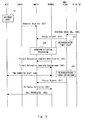
- FIG. 7 A flow of incoming voice call processing according to a fourth exemplary embodiment of the present invention is described hereinafter with reference to Fig. 7 . It is assumed that the processing of Fig. 3 has been already performed before executing the processing of Fig. 7 , and the UE 35 and the MME 15 are in the ECM-CONNECTED state. Steps S81 to S87 are the same as Steps S41 to S47 in Fig. 5 and not redundantly described in detail.
- Step S88 the MME 15 sends a Forward Relocation Complete Acknowledge message as a response signal to the Forward Relocation Complete Notification message sent from the SGSN 20 (S88).
- the MME 15 sets information indicating execution of calling to the UE 35 to the Forward Relocation Complete Acknowledge message.
- the MME 15 sets information which is set to the CS Paging Indication message in Step S36 of Fig. 4 to the Forward Relocation Complete Acknowledge message and sends it.
- the MME 15 sets information which is set to the CS Paging Indication message to the Forward Relocation Complete Acknowledge message and sends it in Step S88, it is possible to notify the UE 35 about completion of handover processing and further indicate calling.
- the UE 35 and the SGSN 20 become the ECM-CONNECTED state (S89). Then, the SGSN 20 performs call attempt to the UE 35 based on the indication of calling to the UE 35 notified in Step S88 (S90).
- the MME 15 sets information indicating execution of calling to the UE 35 to the Forward Relocation Complete Acknowledge message that notifies completion of handover processing. This eliminates the need to send the CS Paging Indication message which is sent in Step S70 of Fig. 6 and thereby reduces the number of messages between the MME 15 and the SGSN 20. It is thereby possible to reduce the processing load of the network.
- FIG. 8 shows the operation in the case where a conflict between handover processing and incoming voice call processing does not occur and a notification of an incoming voice call is successfully given to the UE 35, for comparison with the operation examples shown in Figs. 4 to 7 . It is assumed that the processing of Fig. 3 has been already performed before executing the processing of Fig. 8 , and the UE 35 and the MME 15 are in the ECM-CONNECTED state.
- the MSC/VLR 45 receives an incoming voice call message sent from a voice network (S91).
- the MSC/VLR 45 sends a Paging Request message to the MME 15 (S92).
- the MSC/VLR 45 starts the retransmission timer that specifies the timing to retransmit the Paging message (S93).
- the MME 15 sends a CS Service Notification message to notify the UE 35 through the eNB 70 about an incoming voice call (S94).
- the UE 35 sends a NAS extended Service Request message to the MME 15 through the eNB 70 (S95).
- the MME 15 sends a response message (Service Request message) indicating that an incoming voice call is accepted to the MSC/VLR 45 (S96).
- the response message can also notify the MSC/VLR 45 that the UE 35 is in the ECM-CONNECTED state.
- the MSC/VLR 45 stops the timer that has been started to retransmit the incoming voice call message (Paging Request message). By this operation, processing to retransmit the Paging Request message in the MSC/VLR 45 is stopped (S97). After that, the UE 35 moves to the 3G wireless area, and an incoming call operation using the 2G/3G radio control device 80 and the MSC/VLR 45 is continued (S98).
- the present invention is described as a hardware configuration in the above exemplary embodiments, the present invention is not limited thereto.
- the present invention may be implemented by causing a CPU (Central Processing Unit) to execute a computer program to perform processing of the mobility management device, the switching device or the SGSN.
- a CPU Central Processing Unit
- the program can be stored and provided to the computer using any type of non-transitory computer readable medium.
- the non-transitory computer readable medium includes any type of tangible storage medium. Examples of the non-transitory computer readable medium include magnetic storage media (such as floppy disks, magnetic tapes, hard disk drives, etc.), optical magnetic storage media (e.g. magneto-optical disks), CD-ROM (Read Only Memory), CD-R , CD-R/W, and semiconductor memories (such as mask ROM, PROM (Programmable ROM), EPROM (Erasable PROM), flash ROM, RAM (Random Access Memory), etc.).
- the program may be provided to a computer using any type of transitory computer readable medium. Examples of the transitory computer readable medium include electric signals, optical signals, and electromagnetic waves.
- the transitory computer readable medium can provide the program to a computer via a wired communication line such as an electric wire or optical fiber or a wireless communication line.
- the present invention is not limited to the above-described exemplary embodiments but is susceptible of numerous changes and modifications as known to those skilled in the art; for example, the 2G/3G radio control device 80 may be a 3G radio control device, and the MSC/VLR 45 may be composed of separate MSC and VLR devices.
Abstract
Description
- The present invention relates to a mobility management device, a communication system, an incoming voice call control method and a program and, for example, relates to a mobility management device, a communication system, an incoming voice call control method and a program using the ISR feature. An incoming voice call described in this invention includes a multimedia communication such as a video telephone.
- In the 3GPP (Third Generation Partnership Project) that defines a standard for mobile network systems, EPC (Evolved Packet Core) is specified as the next generation mobile network system. The EPC is a network system that accommodates an LTE (Long Term Evolution) access network in addition to radio access networks called the second generation and the third generation.
- The state where a mobile communication device that is located in an LTE wireless area is connected to the EPC is referred to as "ECM-CONNECTED" state. The mobile communication device may be referred to as a mobile terminal device. Further, the mobile communication device is defined as a UE (User Equipment) in the 3GPP. Furthermore, a device that manages the location of the UE that is located in the LTE wireless area is MME (Mobility Management Entity), and a device that manages the location of the UE that is located in the second and third generation wireless area (which is referred to as "3G wireless area") is SGSN (Serving GPRS Support Node).
- It is anticipated that, initially after introduction of the LTE wireless area, the LTE wireless area will be gradually broadened, overlaying the 3G wireless area. In the case where the LTE wireless area and the 3G wireless area overlap and the LTE wireless area is small, switching between the LTE wireless area and the 3G wireless area is anticipated to occur frequently in the UE that is located at the end of the LTE wireless area. The frequent switching between the LTE wireless area and the 3G wireless area causes problems such as an increase in network processing load due to location registration processing and battery consumption of the UE.
- In Non Patent Literature 1, the LTE/3G location registration skip feature (ISR (Idle mode Signaling Reduction) feature; hereinafter referred to as the ISR feature) that does not carry out location registration even when a UE moves to a different area unless there is no change in the location registration area that has been registered before in the LTE wireless area and the 3G wireless area. Enabling the ISR reduces the number of times location registration is carried out, and it is thereby possible to solve the problems of an increase in network processing load and UE battery consumption.
- [NPL 1] "SAE basic control technology to achieve the ALL-IP network", NTT DOCOMO Technical Journal, Vol.17, No.3, October 2009
- In the case where a UE in the ECM-CONNECTED state is located in the location registration area under control of the MME and when an incoming voice call is made from MSC(Mobile Switching Center)/VLR(Visitor Location Register) to the UE, the MSC/VLR notifies the MME that an incoming voice call to the UE has occurred. The MME notifies the MSC/VLR that it has received the incoming voice call to the UE. Further, the MME notifies the UE that the incoming voice call has arrived. At this time, the MSC/VLR stops a timer for retransmission of an incoming call notification and enters a mode to wait for a response from the UE because the incoming voice call notification has been accepted. Note that, if the MME sends an incoming call notification to the UE during the processing (handover) that the UE moves from the location registration area under control of the MME to the location registration area under control of the SGSN, the incoming call notification does not reach the UE in some cases.
- If the UE is moved to the location registration area under control of the MME or the SGSN where the ISR is not activated, location registration for an incoming voice call is newly performed by the UE for the MSC/VLR in the location registration area under control of the MME or the SGSN where the ISR is not activated to which the UE is moved. Therefore, the MSC/VLR can notify the incoming voice call again to the UE located in the location registration area under control of the MME or the SGSN where the ISR is not activated to which the UE is moved. On the other hand, when the UE is moved to the location registration area under control of the SGSN where the ISR is activated, location registration is not performed by the UE. Therefore, when the MME sends an incoming call notification to the UE during handover of the UE and therefore the incoming call notification does not reach the UE, the MSC/VLR cannot notify the incoming voice call again to the UE located in the location registration area under control of the SGSN where the ISR is activated, which causes a failure in an incoming voice call to the UE.
- An exemplary object of the invention is to normally provide a UE with a notification of an incoming voice call that is made when ISR is activated in an MME and an SGSN and when a mobile communication device is moving from a location registration area under control of the MME to a location registration area under control of the SGSN.
- A mobility management device according to a first exemplary aspect of the invention is a mobility management device that makes an ISR feature operate in collaboration with an SGSN and includes an incoming voice call control unit that sends a response message indicating that a mobile communication device is moving to a switching device in response to an incoming voice call message notified from the switching device and, when the incoming voice call message is sent again from the switching device after a lapse of a specified period of time, performs call attempt to the mobile communication device through the SGSN, in a case where a second location registration area managed by the mobility management device exists within a first location registration area managed by the SGSN, and an incoming voice call is made to the mobile communication device during when the mobile communication device is moving out of the second location registration area in the first location registration area.
- A communication system according to a second exemplary aspect of the invention includes an SGSN that manages a first location registration area, a mobility management device that manages a second location registration area overlapping a part of the first location registration area, and a switching device that notifies an incoming voice call to a mobile communication device through the mobility management device, and, in a case where an incoming voice call is made to the mobile communication device during when the mobile communication device is moving out of the second location registration area in the first location registration area, the mobility management device sends a response message indicating that the mobile communication device is moving to the switching device in response to an incoming voice call message notified from the switching device and, when the incoming voice call message is sent again from the switching device after a lapse of a specified period of time, performs call attempt to the mobile communication device through the SGSN.
- An incoming voice call control method according to a third exemplary aspect of the invention is an incoming voice call control method executed in a mobility management device that makes an ISR feature operate in collaboration with an SGSN, and, in a case where a second location registration area managed by the mobility management device exists within a first location registration area managed by the SGSN, and an incoming voice call is made to a mobile communication device during when the mobile communication device is moving out of the second location registration area in the first location registration area, the method sends a response message indicating that the mobile communication device is moving to a switching device in response to an incoming voice call message notified from the switching device and, when the incoming voice call message is sent again from the switching device after a lapse of a specified period of time, performs call attempt to the mobile communication device through the SGSN.
- A program according to a fourth exemplary aspect of the invention is a program executed by a computer of a mobility management device that makes an ISR feature operate in collaboration with an SGSN, the program causing the computer to execute a step of sending a response message indicating that a mobile communication device is moving to a switching device in response to an incoming voice call message notified from the switching device, and a step of performing call attempt to the mobile communication device through the SGSN when the incoming voice call message is sent again from the switching device after a lapse of a specified period of time, in a case where a second location registration area managed by the mobility management device exists within a first location registration area managed by the SGSN, and an incoming voice call is made to the mobile communication device during when the mobile communication device is moving out of the second location registration area in the first location registration area.
- According to the invention, it is possible to provide a mobility management device, a communication system, a voice incoming call control method and a program that can normally provide a UE with a notification of an incoming voice call that is made when ISR is activated in an MME and an SGSN and when a mobile communication device is moving from a location registration area under control of the MME to a location registration area under control of the SGSN in the ECM-CONNECTED state.
-
-
Fig. 1 is a configuration diagram of a communication system according to a first exemplary embodiment; -
Fig. 2 is a configuration diagram of a communication system according to a second exemplary embodiment; -
Fig. 3 is a diagram showing a flow of processing to connect a UE to a network according to the second exemplary embodiment; -
Fig. 4 is a diagram showing a flow of incoming voice call processing according to the second exemplary embodiment; -
Fig. 5 is a diagram showing a flow of incoming voice call processing according to a third exemplary embodiment; -
Fig. 6 is a diagram showing a flow of incoming voice call processing according to a fourth exemplary embodiment; -
Fig. 7 is a diagram showing a flow of incoming voice call processing according to a fifth exemplary embodiment; and -
Fig. 8 is a diagram showing a flow of incoming voice call processing according to a fifth exemplary embodiment. - Exemplary embodiments of the present invention are described hereinafter with reference to the drawings. A configuration example of a communication system according to a first exemplary embodiment of the invention is described with reference to
Fig. 1 . The communication system shown inFig. 1 is composed of node devices specified in the 3GPP. The communication system inFig. 1 includes amobility management device 10, an SGSN 20, amobile communication device 30, and aswitching device 40. - The
mobility management device 10 and the SGSN 20 make the ISR feature operate in collaboration with each other. Stated differently, themobility management device 10 and the SGSN 20 enable the ISR feature incorporated in each of them. The SGSN 20 manages alocation registration area 50. Themobility management device 10 manages alocation registration area 60. Thelocation registration area 50 includes thelocation registration area 60. Accordingly, a part of thelocation registration area 50 and thelocation registration area 60 are overlapping areas. - In
Fig. 1 , themobile communication device 30 moves out of thelocation registration area 60 in thelocation registration area 50. - The
switching device 40 notifies themobile communication device 30 through themobility management device 10 about an incoming voice call. In the case where themobile communication device 30 is located inside thelocation registration area 60, theswitching device 40 notifies themobile communication device 30 through themobility management device 10 about the incoming voice call. In the case where themobile communication device 30 is located outside thelocation registration area 60 and inside thelocation registration area 50, theswitching device 40 notifies themobile communication device 30 through themobility management device 10 and the SGSN 20 about the incoming voice call and the SGSN 20. - A configuration example of the
mobility management device 10 is described hereinafter. Themobility management device 10 includes an incoming voicecall control unit 11. The case where an incoming voice call is made to themobile communication device 30 during the time when themobile communication device 30 is moving out of thelocation registration area 60 in thelocation registration area 50 is described. "During moving" is the state where processing for movement of themobile communication device 30 has not yet completed in themobility management device 10 and the SGSN 20 and, for example, the state where handover processing for themobile communication device 30 has not yet completed therein. - In the case where the incoming voice
call control unit 11 detects that themobile communication device 30 has moved out of thelocation registration area 60 when an incoming voice call message is notified from theswitching device 40, the incoming voicecall control unit 11 sends a response message indicating that themobile communication device 30 is during its movement to theswitching device 40. For example, the incoming voicecall control unit 11 may detect that themobile communication device 30 has moved out of thelocation registration area 60 when it performs incoming call processing for themobile communication device 30 and then receives a notification that transmission of an incoming voice call notification message to themobile communication device 30 has failed from a base station that has been managing themobile communication device 30. When an incoming voice call is not normally notified to themobile communication device 30 through themobility management device 10, the switchingdevice 40 retransmits the incoming voice call message after the lapse of a specified period of time. - At the time when the incoming voice call message is retransmitted from the switching
device 40 after the lapse of a specified period of time, themobile communication device 30 has completed handover to the position outside thelocation registration area 60 and inside thelocation registration area 50, and therefore the incoming voicecall control unit 11 sends a message indicating a call of themobile communication device 30 to theSGSN 20. In other words, themobility management device 10 performs call attempt to themobile communication device 30 through theSGSN 20. - As described above, with use of the communication device shown in
Fig. 1 , even in the case where an incoming voice call is made to themobile communication device 30 when the ISR feature is activated in themobility management device 10 and theSGSN 20 and during the time when themobile communication device 30 is moving out of thelocation registration area 60 in thelocation registration area 50, the switchingdevice 40 can successfully notify themobile communication device 30 about an incoming voice call. - In general, in the case where the ISR feature is activated in the
mobility management device 10 and theSGSN 20, location registration processing of themobile communication device 30 is not executed even when themobile communication device 30 has moved out of thelocation registration area 60 in thelocation registration area 50. For example, in the case where an incoming voice call to themobile communication device 30 is made before movement processing of themobile communication device 30 ends, that is, before handover processing ends, themobility management device 10 performs call attempt to themobile communication device 30, assuming that themobile communication device 30 is located within thelocation registration area 60. At this time, if themobility management device 10 accepts the incoming voice call message notified from the switchingdevice 40, the switchingdevice 40 stops a retransmission timer for the incoming voice call message and therefore does not retransmit the incoming voice call message to themobility management device 10. In such a case, because the ISR feature is activated, themobile communication device 30 does not perform location registration processing for theswitching device 40. Accordingly, the switchingdevice 40 does not have a chance to send the incoming voice call message again to themobile communication device 30 that has moved out of thelocation registration area 60. - Therefore, in the case where the
mobility management device 10 fails in calling themobile communication device 30, the switchingdevice 40 cannot send the incoming voice call message to themobile communication device 30. - On the other hand, with use of the communication device shown in
Fig. 1 , in response to an incoming voice call message notified from the switching device, themobility management device 10 sends a response message indicating that themobile communication device 30 is during its movement, instead of sending a message indicating that the incoming voice call message is received, to theswitching device 40. It is thereby possible to prevent theswitching device 40 from stopping the retransmission timer, and themobility management device 10 receives the incoming voice call message again after expiration of the retransmission timer in theswitching device 40. - By the time when the
mobility management device 10 receives the incoming voice call message again, handover processing of themobile communication device 30 has completed because of the lapse of a specified period of time, and therefore it is possible to perform call attempt to themobile communication device 30 through theSGSN 20. The retransmission timer for an incoming voice call message in theswitching device 40 may be set in consideration of the execution time of handover processing of themobile communication device 30. As described above, with use of the communication device shown inFig. 1 , it is possible to reliably notify themobile communication device 30 about the incoming voice call message. - A configuration example of a communication system according to a second exemplary embodiment of the invention is described with reference to
Fig. 2 . The communication system shown inFig. 2 includes anMME 15, anSGSN 20, aUE 35, an MSC/VLR 45, an eNB (evolvedNode B) 70 and a 2G/3Gradio control device 80. The MSC/VLR 45 is connected to an external network. - The
MME 15 is equivalent of themobility management device 10 inFig. 1 . The MSC/VLR 45 is equivalent of theswitching device 40 inFig. 1 . TheUE 35 is equivalent of themobile communication device 30 inFig. 1 . TheeNB 70 is a base station device that manages the LTE wireless area. The 2G/3Gradio control device 80 is a radio control device that manages the 2G or 3G wireless area. The 2G/3Gradio control device 80 may be an RNC (Radio Network Controller) specified in the 3GPP, for example. - The
UE 35 is a communication device that is specified as a mobile communication device in the 3GPP. TheUE 35 may be a cellular phone, a smartphone, a tablet terminal, a personal computer with a communication function or the like, for example. Further, theUE 35 may be an M2M (Machine To Machine) device that performs communications in an autonomous manner. The M2M device may be a device that does not often move such as an automatic vending machine or an electrical appliance having a communication function, or a watch worn by a user and the like, for example. - Hereinafter, a flow of processing to connect the
UE 35 to a network is described with reference toFig. 3 . First, theUE 35 sends a Combined Attach Request message to theMME 15 in order to make a request for registration of a line attachment location (S11). Receiving the Combined Attach Request message, theMME 15 generates location registration information of theUE 35. The location registration information contains information indicating that theUE 35 is located within the location registration area managed by theMME 15 or subscriber information of theUE 35, for example. The subscriber information of theUE 35 may be acquired from a subscriber information management device (not shown) that is placed in the mobile communication system. The subscriber information management device is specified as HSS (Home Subscriber Server) in the 3GPP, for example. - Next, the
MME 15 establishes SGs association with the MSC/VLR 45 (S12). The SGs association is used to send and receive an incoming voice call message (CS (Call Switch) control signal) between theMME 15 and the MSC/VLR 45. After establishing the SGs association with the MSC/VLR 45, theMME 15 sends a Combined Attach Accept message to the UE 35 (S13). - Then, the
UE 35 sends a Routing Area Update Request message to the SGSN 20 (S14). Receiving the Routing Area Update Request message, theSGSN 20 generates location registration information of theUE 35. - Then, the location registration information is synchronized between the
SGSN 20 and theMME 15 to enable the ISR (S15). TheSGSN 20 then sends a Routing Area Update Accept message to the UE 35 (S16). After execution of the processing in Steps S11 to S16, theUE 35 and theMME 15 become ECM-CONNECTED state (S17). The ECM-CONNECTED state is a state where a communication path for user data is established between the network and theUE 35. - A flow of incoming voice call processing for the
UE 35 is described hereinafter with reference toFig. 4 . It is assumed that the processing ofFig. 3 has been already performed before executing the processing ofFig. 4 , and theUE 35 and theMME 15 are in the ECM-CONNECTED state. - First, the MSC/
VLR 45 receives an incoming voice call message sent from a voice network (S21). Next, the MSC/VLR 45 sends a Paging Request message to the MME 15 (S22). The MSC/VLR 45 sends the Paging Request message through the SGs association established between the MSC/VLR 45 and theMME 15. In other words, the MSC/VLR 45 sends the Paging Request message by the SGs interface. After sending the Paging Request message, the MSC/VLR 45 starts a retransmission timer that specifies the timing to retransmit the Paging message (S23). - Even when the
MME 15 receives the Paging Request message, it does not send a response message (Service Request message) indicating that an incoming voice call is accepted to the MSC/VLR 45. If an incoming voice call is accepted by theMME 15, the MSC/VLR 45 stops the timer that has been started to retransmit the incoming voice call message (Paging Request message). Thus, in order to prevent the retransmission timer from stopping, theMME 15 does not send the Service Request message to the MSC/VLR 45. - Then, the
MME 15 sends a CS Service Notification message to notify theUE 35 through theeNB 70 about an incoming voice call (S24). It is noted that theUE 35 starts moving out of thelocation registration area 60 before the CS Service Notification message is sent from the eNB 70 (S25). In this case, theeNB 70 abandons transmission of the CS Service Notification message to the UE 35 (S26) based on that fact that theUE 35 has already started moving out of thelocation registration area 60. Note that, although the case where transmission of the CS Service Notification message to the UE 35 (S26) is abandoned is described in the following description, when theeNB 70 sends the CS Service Notification message to theUE 35 and then a response message (NAS extended Service Request message) is sent from theUE 35 to theMME 15 after that, theMME 15 sends a Service Request message to the MSC/VLR 45 upon receiving the NAS extended Service Request message. - Then, the
eNB 70 sends a NAS Non-Delivery Indication message indicating that transmission of the CS Service Notification message to theUE 35 has failed to the MME 15 (S27). Receiving the NAS Non-Delivery Indication message, theMME 15 sends a paging reject message to which cause is set indicating failure of transmission of the CS Service Notification message to theUE 35 due to movement of theUE 35 to the MSC/VLR 45 (S28). - Then, the
eNB 70 sends a Handover Required message to theMME 15 in order to start handover processing of the UE 35 (S29). TheMME 15 performs handover processing with the SGSN 20 (S30). After registration of theUE 35 is done in the handover processing, theSGSN 20 sends a Forward Relocation Complete Notification message to the MME 15 (S31). Then, theMME 15 sends a Forward Relocation Complete Acknowledge message to theSGSN 20 as a response message to the Forward Relocation Complete Notification message (S32). After the handover processing of theUE 35 is completed in the above manner, theUE 35 and theSGSN 20 become PMM-CONNECTED state. The PMM-CONNECTED state is a state where a communication path for user data is established between the network and theUE 35. - Then, when the retransmission timer for the Paging Request message expires, the MSC/
VLR 45 retransmits the Paging Request message to the MME 15 (S35). TheMME 15 then sends a CS Paging Indication message with an indication to perform call attempt to theUE 35 to theSGSN 20 since theUE 35 has already moved to the area under control of the SGSN 20 (S36). TheSGSN 20 then performs call attempt to the UE 35 (S37). - As described above, by executing the incoming voice call processing shown in
Fig. 4 , it is possible to prevent the retransmission timer from stopping in the MSC/VLR 45. The MSC/VLR 45 can thereby send the Paging Request message again to theMME 15 and therefore notify theUE 35 after the handover is done about an incoming voice call. - A flow of incoming voice call processing for the
UE 35 according to a third exemplary embodiment of the invention is described hereinafter with reference toFig. 5 . It is assumed that the processing ofFig. 3 has been already performed before executing the processing ofFig. 5 , and theUE 35 and theMME 15 are in the ECM-CONNECTED state. - First, the
UE 35 starts moving out of thelocation registration area 60 in the location registration area 50 (S41). Next, theeNB 70 sends a Handover Required message to theMME 15 in order to start handover processing of the UE 35 (S42). In the EPC, which is the network, the Handover Required message is the first message in the handover processing. The MSC/VLR 45 receives an incoming voice call message sent from the voice network (S43). The MSC/VLR 45 then sends a Paging Request message to the MME 15 (S44). After sending the Paging Request message, the MSC/VLR 45 starts the retransmission timer that specifies the timing to retransmit the Paging message (S45). -
Fig. 5 is different fromFig. 4 in that theMME 15 receives the Paging Request message after receiving the Handover Required message. In the case of receiving the messages in this order, theMME 15 does not perform processing that accompanies reception of the Paging Request message. Specifically, inFig. 5 , theMME 15 does not perform the processing in Steps S24 to S28 inFig. 4 . In other words, theMME 15 does not perform transmission of the CS Service Notification message to theUE 35, which is processing in response to reception of the Paging Request message, and abandons or discards the Paging Request message. On the other hand, theMME 15 preferentially performs processing that accompanies reception of the Handover Required message, rather than processing that accompanies reception of the Paging Request message, which is incoming call processing to theUE 35. - Steps S46 to S53 are the same as Steps S30 to S37 in
Fig. 4 and not redundantly described in detail. In this figure, theMME 15 does not send the CS Service Notification message to theeNB 70 when it first receives the Paging Request message sent from the MSC/VLR 45 in Step S44. When the Paging Request message is sent in Step S51 upon expiration of the retransmission timer in the MSC/VLR 45, theMME 15 performs call attempt to theUE 35 through theSGSN 20. - As described above, by performing the flow of the incoming voice call processing in
Fig. 5 , even when an incoming voice call is made to theUE 35 during execution of handover processing of theUE 35, it is possible to notify theUE 35 about the incoming voice call after completion of the handover processing of theUE 35. - Further, the
MME 15 does not perform incoming voice call processing in response to the Paging Request message received first, and performs call attempt to theUE 35 only after the Paging Request message is retransmitted after that, which allows reduction of the number of signals in the network compared to the case ofFig. 4 . It is thereby possible to simplify the flow of the incoming voice call processing and reduce the processing load of the network. - A flow of incoming voice call processing according to a third exemplary embodiment of the present invention is described hereinafter with reference to
Fig. 6 . It is assumed that the processing ofFig. 3 has been already performed before executing the processing ofFig. 6 , and theUE 35 and theMME 15 are in the ECM-CONNECTED state. Steps S61 to S69 are the same as Steps S41 to S49 inFig. 5 and not redundantly described in detail. - In
Fig. 6 , at the time when theUE 35 and theSGSN 20 have become the PMM-CONNECTED state (S69) after completion of handover processing, theMME 15 sends a CS Paging Indication message to theSGSN 20 if it has received the Paging Request message during the handover processing (S70). Note that theMME 15 determines that theUE 35 and theSGSN 20 have become the PMM-CONNECTED state (S69) by sending a Forward Relocation Complete Acknowledge message to theSGSN 20 in Step S68 and then sends a CS Paging Indication message to the SGSN 20 (S70). - In
Fig. 5 , theMME 15 sends the CS Paging Indication message to theSGSN 20 upon transmission of the Paging Request message from the MSC/VLR 45. On the other hand, in this figure, theMME 15 sends the CS Paging Indication message to theSGSN 20 upon completion of handover processing without waiting for retransmission of the Paging Request message, which is different from the processing ofFig. 5 . - To implement the processing of this figure, the incoming voice
call control unit 11 of theMME 15 needs to know that the Paging Request message has been received from the MSC/VLR 45 in Step S64. For example, the incoming voicecall control unit 11 may have a Paging Request message reception flag or the like and set the flag to on when it receives the Paging Request message. - As described above, by performing the flow of the incoming voice call processing in
Fig. 6 , even when an incoming voice call is made to theUE 35 during execution of handover processing of theUE 35, it is possible to notify theUE 35 about the incoming voice call after completion of the handover processing of theUE 35. - Further, the
MME 15 can send the CS Paging Indication message to theSGSN 20 without waiting for retransmission of the Paging Request message, and it is thereby possible to perform call attempt to theUE 35 earlier than the case ofFig. 5 . - A flow of incoming voice call processing according to a fourth exemplary embodiment of the present invention is described hereinafter with reference to
Fig. 7 . It is assumed that the processing ofFig. 3 has been already performed before executing the processing ofFig. 7 , and theUE 35 and theMME 15 are in the ECM-CONNECTED state. Steps S81 to S87 are the same as Steps S41 to S47 inFig. 5 and not redundantly described in detail. - In Step S88, the
MME 15 sends a Forward Relocation Complete Acknowledge message as a response signal to the Forward Relocation Complete Notification message sent from the SGSN 20 (S88). In this step, theMME 15 sets information indicating execution of calling to theUE 35 to the Forward Relocation Complete Acknowledge message. Specifically, theMME 15 sets information which is set to the CS Paging Indication message in Step S36 ofFig. 4 to the Forward Relocation Complete Acknowledge message and sends it. - Because the
MME 15 sets information which is set to the CS Paging Indication message to the Forward Relocation Complete Acknowledge message and sends it in Step S88, it is possible to notify theUE 35 about completion of handover processing and further indicate calling. - Next, upon completion of the handover processing, the
UE 35 and theSGSN 20 become the ECM-CONNECTED state (S89). Then, theSGSN 20 performs call attempt to theUE 35 based on the indication of calling to theUE 35 notified in Step S88 (S90). - As described above, by performing the flow of the incoming voice call processing in
Fig. 7 , even when an incoming voice call is made to theUE 35 during execution of handover processing of theUE 35, it is possible to notify theUE 35 about the incoming voice call after completion of the handover processing of theUE 35. - Further, the
MME 15 sets information indicating execution of calling to theUE 35 to the Forward Relocation Complete Acknowledge message that notifies completion of handover processing. This eliminates the need to send the CS Paging Indication message which is sent in Step S70 ofFig. 6 and thereby reduces the number of messages between theMME 15 and theSGSN 20. It is thereby possible to reduce the processing load of the network. - Furthermore, because the number of messages can be reduced compared with the case of
Fig. 6 , it is possible to perform call attempt to theUE 35 earlier than the processing ofFig. 6 . - A flow of incoming voice call processing for the
UE 35 is described hereinafter with reference toFig. 8. Fig. 8 shows the operation in the case where a conflict between handover processing and incoming voice call processing does not occur and a notification of an incoming voice call is successfully given to theUE 35, for comparison with the operation examples shown inFigs. 4 to 7 . It is assumed that the processing ofFig. 3 has been already performed before executing the processing ofFig. 8 , and theUE 35 and theMME 15 are in the ECM-CONNECTED state. - First, the MSC/
VLR 45 receives an incoming voice call message sent from a voice network (S91). Next, the MSC/VLR 45 sends a Paging Request message to the MME 15 (S92). After sending the Paging Request message, the MSC/VLR 45 starts the retransmission timer that specifies the timing to retransmit the Paging message (S93). - Then, the
MME 15 sends a CS Service Notification message to notify theUE 35 through theeNB 70 about an incoming voice call (S94). - Receiving the CS Service Notification, the
UE 35 sends a NAS extended Service Request message to theMME 15 through the eNB 70 (S95). - Receiving the NAS extended Service Request message, the
MME 15 sends a response message (Service Request message) indicating that an incoming voice call is accepted to the MSC/VLR 45 (S96). The response message (Service Request message) can also notify the MSC/VLR 45 that theUE 35 is in the ECM-CONNECTED state. When the incoming voice call is accepted by theMME 15, the MSC/VLR 45 stops the timer that has been started to retransmit the incoming voice call message (Paging Request message). By this operation, processing to retransmit the Paging Request message in the MSC/VLR 45 is stopped (S97). After that, theUE 35 moves to the 3G wireless area, and an incoming call operation using the 2G/3Gradio control device 80 and the MSC/VLR 45 is continued (S98). - Although the present invention is described as a hardware configuration in the above exemplary embodiments, the present invention is not limited thereto. The present invention may be implemented by causing a CPU (Central Processing Unit) to execute a computer program to perform processing of the mobility management device, the switching device or the SGSN.
- In the above example, the program can be stored and provided to the computer using any type of non-transitory computer readable medium. The non-transitory computer readable medium includes any type of tangible storage medium. Examples of the non-transitory computer readable medium include magnetic storage media (such as floppy disks, magnetic tapes, hard disk drives, etc.), optical magnetic storage media (e.g. magneto-optical disks), CD-ROM (Read Only Memory), CD-R , CD-R/W, and semiconductor memories (such as mask ROM, PROM (Programmable ROM), EPROM (Erasable PROM), flash ROM, RAM (Random Access Memory), etc.). The program may be provided to a computer using any type of transitory computer readable medium. Examples of the transitory computer readable medium include electric signals, optical signals, and electromagnetic waves. The transitory computer readable medium can provide the program to a computer via a wired communication line such as an electric wire or optical fiber or a wireless communication line.
- It should be noted that the present invention is not limited to the above-described exemplary embodiments but is susceptible of numerous changes and modifications as known to those skilled in the art; for example, the 2G/3G
radio control device 80 may be a 3G radio control device, and the MSC/VLR 45 may be composed of separate MSC and VLR devices. - While the invention has been particularly shown and described with reference to exemplary embodiments thereof, the invention is not limited to these embodiments. It will be understood by those of ordinary skill in the art that various changes in form and details may be made therein without departing from the spirit and scope of the present invention as defined by the claims.
- This application is based upon and claims the benefit of priority from Japanese patent application No.
2013-079961 filed on April 5, 2013 2013-141828 filed on July 5, 2013 -
- 10
- MOBILITY MANAGEMENT DEVICE
- 11
- INCOMING VOICE CALL CONTROL UNIT
- 15
- MME
- 20
- SGSN
- 30
- MOBILE COMMUNICATION DEVICE
- 35
- UE
- 40
- SWITCHING DEVICE
- 45
- MSC/VLR
- 50
- LOCATION REGISTRATION AREA
- 60
- LOCATION REGISTRATION AREA
- 70
- eNB
- 80
- 2G/3G RADIO CONTROL DEVICE
Claims (13)
- A mobile communication system comprising:a terminal (UE (User Equipment)) that performs handover procedure from an LTE (Long Term Evolution) wireless area to a 3G wireless area or a 2G wireless area; andan MME (Mobility Management Entity) that discards, if the handover procedure is ongoing when the MME receives a paging request message for the terminal over an SGs interface, the paging request message.
- An MME (Mobility Management Entity) used in a mobile communication system, wherein
if handover procedure from an LTE wireless area to a 3G wireless area or a 2G wireless area is ongoing when the MME receives a paging request message for the terminal (UE) over an SGs interface, the MME discards the paging request message. - An incoming call control method in a mobile communication system, comprising:performing, by a terminal (UE), handover procedure processing from an LTE wireless area to a 3G wireless area or a 2G wireless area; anddiscarding, by an MME (Mobility Management Entity), if the handover procedure is ongoing when the MME receives a paging request message for the terminal over an SGs interface, the paging request message
- An incoming call control method by an MME (Mobility Management Entity) used in a mobile communication system, comprising:discarding, if handover procedure from an LTE wireless area to a 3G wireless area or a 2G wireless area is ongoing when the MME receives a paging request message for the terminal (UE) over an SGs interface, the paging request message.
- A control method of a terminal (UE) used in a mobile communication system, comprising:performing, by the terminal, handover procedure processing from an LTE wireless area to a 3G wireless area or a 2G wireless area; anddiscarding, by an MME (Mobility Management Entity), if the handover procedure is ongoing when the MME receives a paging request message for the terminal over an SGs interface, the paging request message.
- The mobile communication system according to Claim 1,
wherein
the MME does not perform further incoming call processing to the terminal after discarding the paging request message and, when receiving retransmission of the paging request message from a switching device (MSC/VLR (Mobile Switching Center/Visitor Location Register)), continues the incoming call processing. - The mobile communication system according to Claim 6,
wherein
the switching device performs retransmission of the paging request message by starting a timer. - The MME according to Claim 2, wherein
the MME does not perform further incoming call processing to the terminal after discarding the paging request message and, when receiving retransmission of the paging request message from a switching device (MSC/VLR (Mobile Switching Center/Visitor Location Register)), continues the incoming call processing. - The MME according to Claim 8, wherein
the switching device performs retransmission of the paging request message by starting a timer. - The incoming call control method in the mobile communication system according to Claim 3, wherein
the MME does not perform further incoming call processing to the terminal after discarding the paging request message and, when receiving retransmission of the paging request message from a switching device (MSC/VLR (Mobile Switching Center/Visitor Location Register)), continues the incoming call processing. - The incoming call control method in the mobile communication system according to Claim 10, wherein
the switching device performs retransmission of the paging request message by starting a timer. - The incoming call control method by the MME according to Claim 4, wherein
the MME does not perform further incoming call processing to the terminal after discarding the paging request message and, when receiving retransmission of the paging request message from a switching device (MSC/VLR (Mobile Switching Center/Visitor Location Register)), continues the incoming call processing. - The incoming call control method by the MME according to Claim 12, wherein
the switching device performs retransmission of the paging request message by starting a timer.
Priority Applications (2)
| Application Number | Priority Date | Filing Date | Title |
|---|---|---|---|
| EP22161716.0A EP4033816A1 (en) | 2013-04-05 | 2013-12-25 | Mme and incoming call control method of mme for paging during ongoing handover |
| EP22161727.7A EP4037381A1 (en) | 2013-04-05 | 2013-12-25 | Mme and incoming call control method of mme for paging during ongoing handover |
Applications Claiming Priority (3)
| Application Number | Priority Date | Filing Date | Title |
|---|---|---|---|
| JP2013079961 | 2013-04-05 | ||
| JP2013141828A JP5525092B1 (en) | 2013-04-05 | 2013-07-05 | Mobility management device, communication system, voice incoming call control method, and program |
| PCT/JP2013/007567 WO2014162375A1 (en) | 2013-04-05 | 2013-12-25 | Mobile communication system, mme, incoming call control method for mobile communication system, and incoming call control method for mme |
Related Child Applications (2)
| Application Number | Title | Priority Date | Filing Date |
|---|---|---|---|
| EP22161716.0A Division EP4033816A1 (en) | 2013-04-05 | 2013-12-25 | Mme and incoming call control method of mme for paging during ongoing handover |
| EP22161727.7A Division EP4037381A1 (en) | 2013-04-05 | 2013-12-25 | Mme and incoming call control method of mme for paging during ongoing handover |
Publications (3)
| Publication Number | Publication Date |
|---|---|
| EP2874440A1 true EP2874440A1 (en) | 2015-05-20 |
| EP2874440A4 EP2874440A4 (en) | 2016-04-20 |
| EP2874440B1 EP2874440B1 (en) | 2022-03-23 |
Family
ID=51175712
Family Applications (3)
| Application Number | Title | Priority Date | Filing Date |
|---|---|---|---|
| EP22161716.0A Pending EP4033816A1 (en) | 2013-04-05 | 2013-12-25 | Mme and incoming call control method of mme for paging during ongoing handover |
| EP22161727.7A Pending EP4037381A1 (en) | 2013-04-05 | 2013-12-25 | Mme and incoming call control method of mme for paging during ongoing handover |
| EP13881129.4A Active EP2874440B1 (en) | 2013-04-05 | 2013-12-25 | Mobile communication system, mme, incoming call control method for mobile communication system, and incoming call control method for mme |
Family Applications Before (2)
| Application Number | Title | Priority Date | Filing Date |
|---|---|---|---|
| EP22161716.0A Pending EP4033816A1 (en) | 2013-04-05 | 2013-12-25 | Mme and incoming call control method of mme for paging during ongoing handover |
| EP22161727.7A Pending EP4037381A1 (en) | 2013-04-05 | 2013-12-25 | Mme and incoming call control method of mme for paging during ongoing handover |
Country Status (22)
| Country | Link |
|---|---|
| US (4) | US9344936B2 (en) |
| EP (3) | EP4033816A1 (en) |
| JP (5) | JP5525092B1 (en) |
| KR (1) | KR101652651B1 (en) |
| CN (4) | CN110267252B (en) |
| BR (1) | BR112015003802B1 (en) |
| CL (1) | CL2015000535A1 (en) |
| CR (1) | CR20150155A (en) |
| ES (1) | ES2913334T3 (en) |
| IL (1) | IL237053B (en) |
| IN (1) | IN2015DN01269A (en) |
| MA (1) | MA20150156A1 (en) |
| MX (2) | MX341810B (en) |
| MY (1) | MY172857A (en) |
| NZ (1) | NZ704793A (en) |
| PE (1) | PE20151029A1 (en) |
| PH (1) | PH12015500359A1 (en) |
| RU (5) | RU2607787C1 (en) |
| SA (1) | SA515360057B1 (en) |
| UA (1) | UA113320C2 (en) |
| WO (1) | WO2014162375A1 (en) |
| ZA (2) | ZA201600401B (en) |
Families Citing this family (7)
| Publication number | Priority date | Publication date | Assignee | Title |
|---|---|---|---|---|
| CN104427616B (en) * | 2013-09-10 | 2020-03-03 | 中兴通讯股份有限公司 | Method and device for paging terminal |
| WO2016082187A1 (en) * | 2014-11-28 | 2016-06-02 | 宇龙计算机通信科技(深圳)有限公司 | Terminal, mobility management entity, mobile switching center, and service processing method and system |
| KR20180030241A (en) | 2014-12-22 | 2018-03-21 | 닛본 덴끼 가부시끼가이샤 | Mobile communication system, sgw, terminal, reception method of mobile communication system, reception method of sgw, and reception method of terminal |
| US10218749B2 (en) * | 2016-11-04 | 2019-02-26 | American Teleconferencing Services, Ltd. | Systems, methods, and computer programs for establishing a screen share session for a remote voice call |
| US10278153B2 (en) * | 2017-06-02 | 2019-04-30 | Mediatek Inc. | Method and apparatus for avoiding circuit-switched call drop in mobile communications |
| US10455093B1 (en) | 2018-09-27 | 2019-10-22 | Verizon Patent And Licensing Inc. | System and method for unified call logs with support for call continuity |
| CN111885714B (en) * | 2020-09-08 | 2023-03-24 | 中国联合网络通信集团有限公司 | Paging method and paging device |
Family Cites Families (42)
| Publication number | Priority date | Publication date | Assignee | Title |
|---|---|---|---|---|
| EP1620816B1 (en) | 2003-04-25 | 2013-12-25 | Thomson Reuters Global Resources | Distributed search methods, architectures, systems, and software |
| US7477896B2 (en) * | 2003-08-28 | 2009-01-13 | Qualcomm, Incorporated | Reducing missed pages during cell reselection in a wireless communication system |
| US20080253329A1 (en) * | 2003-12-11 | 2008-10-16 | Matsushita Electric Industrial Co., Ltd. | Communication Handover Method, Communication System, Communication Message Processing Method, and Communication Message Processing Program |
| CN101005692A (en) * | 2006-01-20 | 2007-07-25 | 北京三星通信技术研究有限公司 | Method for reducing terminal switch between LTE and 3G cut-in technology |
| CN101595714B (en) | 2007-01-15 | 2013-06-12 | Lm爱立信电话有限公司 | Method and arrangements for circuit switched services in communication networks |
| CN101489288B (en) * | 2008-01-16 | 2011-04-20 | 华为技术有限公司 | Circuit domain service processing method, system and related device in evolution packet network |
| CN101500212B (en) * | 2008-02-01 | 2011-07-06 | 华为技术有限公司 | Method, apparatus and system for processing circuit domain service by packet domain user |
| CN101499967B (en) * | 2008-02-03 | 2011-07-13 | 中兴通讯股份有限公司 | Circuit domain call implementing method and system |
| CN101296518B (en) * | 2008-06-16 | 2013-01-16 | 中兴通讯股份有限公司 | Circuit field service paging implementing method and apparatus |
| JP5368812B2 (en) * | 2008-07-15 | 2013-12-18 | 京セラ株式会社 | Wireless terminal and communication terminal |
| CN101640933B (en) * | 2008-07-31 | 2012-07-04 | 华为技术有限公司 | Method for paging user equipment, network equipment, user equipment and network system |
| CN101662832A (en) * | 2008-08-26 | 2010-03-03 | 华为技术有限公司 | Method and device for stopping paging and system of device |
| CN102711250B (en) * | 2008-11-07 | 2016-12-07 | 华为技术有限公司 | Paging process, method for information display, Apparatus and system |
| CN101742692B (en) * | 2008-11-07 | 2012-07-04 | 华为技术有限公司 | Paging processing and information display methods, and devices |
| EP2356845B1 (en) * | 2008-12-10 | 2016-04-13 | Telefonaktiebolaget LM Ericsson (publ) | Interface setup for communications network with femtocells |
| US8650290B2 (en) | 2008-12-19 | 2014-02-11 | Openpeak Inc. | Portable computing device and method of operation of same |
| JP4708473B2 (en) * | 2008-12-24 | 2011-06-22 | 株式会社エヌ・ティ・ティ・ドコモ | Communication system, mobile device, incoming call control method |
| CN101790128A (en) * | 2009-01-23 | 2010-07-28 | 大唐移动通信设备有限公司 | Paging method and system |
| WO2010146466A1 (en) * | 2009-06-16 | 2010-12-23 | Research In Motion Limited | Method for accessing a service unavailable through a network cell |
| GB0912944D0 (en) * | 2009-07-24 | 2009-09-02 | Vodafone Plc | SMS over lte sgs interface optimisations |
| CN102026143A (en) * | 2009-09-23 | 2011-04-20 | 华为技术有限公司 | Method and equipment for realizing idle state saving signaling |
| EP2320698B1 (en) * | 2009-11-09 | 2012-07-04 | Research In Motion Limited | Determination of a channel type to be requested in case of a circuit-switched fallback procedure |
| WO2011082552A1 (en) * | 2010-01-11 | 2011-07-14 | 华为技术有限公司 | Method, device and system for implementing resource suspension |
| EP2526730B1 (en) * | 2010-01-21 | 2018-10-10 | LG Electronics Inc. | 1x message bundling |
| GB2477781A (en) * | 2010-02-15 | 2011-08-17 | Nec Corp | Location area-based update procedure in a mobile radio network |
| US10945302B2 (en) * | 2010-03-26 | 2021-03-09 | Interdigital Patent Holdings, Inc. | Managing race conditions between circuit switched fallback requests |
| US20120172066A1 (en) | 2010-04-27 | 2012-07-05 | Nec Corporation | Communication method, mobile network system and device |
| CN104936310B (en) * | 2010-04-27 | 2019-04-16 | 日本电气株式会社 | Communication means, mobile network system and device |
| WO2011134151A1 (en) * | 2010-04-28 | 2011-11-03 | 华为技术有限公司 | Method, device and system for aborting circuit switched fallback call |
| JP2013534090A (en) * | 2010-06-07 | 2013-08-29 | インターデイジタル パテント ホールディングス インコーポレイテッド | Method and apparatus for transmitting a service request message in a congested network |
| EP4213537A1 (en) * | 2010-09-28 | 2023-07-19 | BlackBerry Limited | Method in a core network, mobility management entity and non-transitory storage medium |
| CN102572756B (en) * | 2010-12-30 | 2016-04-13 | 中兴通讯股份有限公司 | The processing method of voice call fallback, Apparatus and system |
| EP2509345A1 (en) * | 2011-04-05 | 2012-10-10 | Panasonic Corporation | Improved small data transmissions for machine-type-communication (MTC) devices |
| CN102740400B (en) * | 2011-04-07 | 2016-08-10 | 宏达国际电子股份有限公司 | The method that the device of handling machine kenel communication triggers |
| WO2011107041A2 (en) * | 2011-04-19 | 2011-09-09 | 华为技术有限公司 | Method and system for processing circuit switched fallback service, mobility management entity and user equipment |
| CN103931217B (en) * | 2011-05-26 | 2017-12-19 | 美福尼亚系统股份有限公司 | The method and system that world-wide web for circuit switching fall-back interconnects |
| JP5650597B2 (en) * | 2011-06-23 | 2015-01-07 | 京セラ株式会社 | Wireless terminal device, communication method, and communication program |
| CN102905369B (en) * | 2011-07-26 | 2018-04-20 | 中兴通讯股份有限公司 | User equipment calling method and system when mobile management unit fails or restarts |
| WO2013048100A1 (en) * | 2011-09-30 | 2013-04-04 | Lg Electronics Inc. | Method for processing data associated with location area update in a wireless communication system |
| EP2579186B1 (en) | 2011-10-04 | 2015-09-09 | ETA SA Manufacture Horlogère Suisse | Method for authenticating an electronic watch and electronic watch for implementing the same |
| AT512357B1 (en) | 2012-01-12 | 2013-09-15 | Flatz Verpackungen Styropor Gmbh | METHOD FOR FOLDING CROPS EXISTING FROM WAVE CAP FOR THE MANUFACTURE OF FOLDING BOXES AND APPARATUS THEREFOR |
| US9247528B2 (en) * | 2012-10-12 | 2016-01-26 | Cisco Technology, Inc. | System and method for reducing paging in UTRAN/GERAN/E-UTRAN networks when idle signaling reduction is active |
-
2013
- 2013-07-05 JP JP2013141828A patent/JP5525092B1/en active Active
- 2013-12-25 CN CN201910553100.XA patent/CN110267252B/en active Active
- 2013-12-25 BR BR112015003802-6A patent/BR112015003802B1/en active IP Right Grant
- 2013-12-25 NZ NZ704793A patent/NZ704793A/en unknown
- 2013-12-25 EP EP22161716.0A patent/EP4033816A1/en active Pending
- 2013-12-25 UA UAA201501904A patent/UA113320C2/en unknown
- 2013-12-25 RU RU2015140359A patent/RU2607787C1/en active
- 2013-12-25 WO PCT/JP2013/007567 patent/WO2014162375A1/en active Application Filing
- 2013-12-25 MA MA37855A patent/MA20150156A1/en unknown
- 2013-12-25 MX MX2015003473A patent/MX341810B/en active IP Right Grant
- 2013-12-25 EP EP22161727.7A patent/EP4037381A1/en active Pending
- 2013-12-25 RU RU2015140360A patent/RU2606545C1/en active
- 2013-12-25 RU RU2015140362A patent/RU2607789C1/en active
- 2013-12-25 PE PE2015000249A patent/PE20151029A1/en active IP Right Grant
- 2013-12-25 MX MX2018007163A patent/MX371233B/en unknown
- 2013-12-25 ES ES13881129T patent/ES2913334T3/en active Active
- 2013-12-25 US US14/419,703 patent/US9344936B2/en active Active
- 2013-12-25 RU RU2015140357A patent/RU2610263C1/en active
- 2013-12-25 CN CN201910553098.6A patent/CN110234107B/en active Active
- 2013-12-25 IN IN1269DEN2015 patent/IN2015DN01269A/en unknown
- 2013-12-25 RU RU2015107558/08A patent/RU2569362C1/en active
- 2013-12-25 CN CN201910554225.4A patent/CN110234108B/en active Active
- 2013-12-25 MY MYPI2015000711A patent/MY172857A/en unknown
- 2013-12-25 KR KR1020157004331A patent/KR101652651B1/en active IP Right Grant
- 2013-12-25 CN CN201380049168.5A patent/CN104662962B/en active Active
- 2013-12-25 EP EP13881129.4A patent/EP2874440B1/en active Active
-
2014
- 2014-04-09 JP JP2014079826A patent/JP5576001B1/en active Active
- 2014-06-24 JP JP2014129333A patent/JP6183912B2/en active Active
-
2015
- 2015-02-02 IL IL237053A patent/IL237053B/en active IP Right Grant
- 2015-02-18 PH PH12015500359A patent/PH12015500359A1/en unknown
- 2015-02-23 SA SA515360057A patent/SA515360057B1/en unknown
- 2015-03-04 CL CL2015000535A patent/CL2015000535A1/en unknown
- 2015-03-20 CR CR20150155A patent/CR20150155A/en unknown
-
2016
- 2016-01-19 ZA ZA2016/00401A patent/ZA201600401B/en unknown
- 2016-01-19 ZA ZA2016/00402A patent/ZA201600402B/en unknown
- 2016-03-01 US US15/057,871 patent/US9596626B2/en active Active
-
2017
- 2017-02-02 US US15/422,962 patent/US9839004B2/en active Active
- 2017-07-26 JP JP2017144387A patent/JP6482097B2/en active Active
- 2017-11-06 US US15/804,579 patent/US10980000B2/en active Active
-
2019
- 2019-02-14 JP JP2019024262A patent/JP6892136B2/en active Active
Also Published As
Similar Documents
| Publication | Publication Date | Title |
|---|---|---|
| US11363507B2 (en) | Mobile communication system, SGW, terminal communication method and control method | |
| US10980000B2 (en) | Mobile communication system, MME, incoming call control method of mobile communication system, and incoming call control method of MME | |
| EP3240329B1 (en) | Method in a serving gateway, sgw, involving change of mme when isr is used |
Legal Events
| Date | Code | Title | Description |
|---|---|---|---|
| PUAI | Public reference made under article 153(3) epc to a published international application that has entered the european phase |
Free format text: ORIGINAL CODE: 0009012 |
|
| 17P | Request for examination filed |
Effective date: 20150213 |
|
| AK | Designated contracting states |
Kind code of ref document: A1 Designated state(s): AL AT BE BG CH CY CZ DE DK EE ES FI FR GB GR HR HU IE IS IT LI LT LU LV MC MK MT NL NO PL PT RO RS SE SI SK SM TR |
|
| AX | Request for extension of the european patent |
Extension state: BA ME |
|
| RA4 | Supplementary search report drawn up and despatched (corrected) |
Effective date: 20160318 |
|
| RIC1 | Information provided on ipc code assigned before grant |
Ipc: H04W 60/00 20090101ALI20160314BHEP Ipc: H04W 48/00 20090101AFI20160314BHEP Ipc: H04W 36/00 20090101ALI20160314BHEP Ipc: H04W 68/12 20090101ALI20160314BHEP Ipc: H04W 48/18 20090101ALI20160314BHEP Ipc: H04W 8/12 20090101ALI20160314BHEP |
|
| DAX | Request for extension of the european patent (deleted) | ||
| STAA | Information on the status of an ep patent application or granted ep patent |
Free format text: STATUS: EXAMINATION IS IN PROGRESS |
|
| 17Q | First examination report despatched |
Effective date: 20190114 |
|
| STAA | Information on the status of an ep patent application or granted ep patent |
Free format text: STATUS: EXAMINATION IS IN PROGRESS |
|
| REG | Reference to a national code |
Ref country code: DE Ref legal event code: R079 Ref document number: 602013081215 Country of ref document: DE Free format text: PREVIOUS MAIN CLASS: H04W0048000000 Ipc: H04W0036000000 |
|
| RIC1 | Information provided on ipc code assigned before grant |
Ipc: H04W 60/04 20090101ALN20210817BHEP Ipc: H04W 8/12 20090101ALI20210817BHEP Ipc: H04W 68/12 20090101ALI20210817BHEP Ipc: H04W 36/00 20090101AFI20210817BHEP |
|
| GRAP | Despatch of communication of intention to grant a patent |
Free format text: ORIGINAL CODE: EPIDOSNIGR1 |
|
| STAA | Information on the status of an ep patent application or granted ep patent |
Free format text: STATUS: GRANT OF PATENT IS INTENDED |
|
| INTG | Intention to grant announced |
Effective date: 20211005 |
|
| GRAS | Grant fee paid |
Free format text: ORIGINAL CODE: EPIDOSNIGR3 |
|
| GRAA | (expected) grant |
Free format text: ORIGINAL CODE: 0009210 |
|
| STAA | Information on the status of an ep patent application or granted ep patent |
Free format text: STATUS: THE PATENT HAS BEEN GRANTED |
|
| AK | Designated contracting states |
Kind code of ref document: B1 Designated state(s): AL AT BE BG CH CY CZ DE DK EE ES FI FR GB GR HR HU IE IS IT LI LT LU LV MC MK MT NL NO PL PT RO RS SE SI SK SM TR |
|
| REG | Reference to a national code |
Ref country code: GB Ref legal event code: FG4D |
|
| REG | Reference to a national code |
Ref country code: CH Ref legal event code: EP |
|
| REG | Reference to a national code |
Ref country code: DE Ref legal event code: R096 Ref document number: 602013081215 Country of ref document: DE |
|
| REG | Reference to a national code |
Ref country code: IE Ref legal event code: FG4D |
|
| REG | Reference to a national code |
Ref country code: AT Ref legal event code: REF Ref document number: 1478281 Country of ref document: AT Kind code of ref document: T Effective date: 20220415 |
|
| REG | Reference to a national code |
Ref country code: NL Ref legal event code: FP |
|
| REG | Reference to a national code |
Ref country code: ES Ref legal event code: FG2A Ref document number: 2913334 Country of ref document: ES Kind code of ref document: T3 Effective date: 20220601 |
|
| REG | Reference to a national code |
Ref country code: LT Ref legal event code: MG9D |
|
| PG25 | Lapsed in a contracting state [announced via postgrant information from national office to epo] |
Ref country code: SE Free format text: LAPSE BECAUSE OF FAILURE TO SUBMIT A TRANSLATION OF THE DESCRIPTION OR TO PAY THE FEE WITHIN THE PRESCRIBED TIME-LIMIT Effective date: 20220323 Ref country code: RS Free format text: LAPSE BECAUSE OF FAILURE TO SUBMIT A TRANSLATION OF THE DESCRIPTION OR TO PAY THE FEE WITHIN THE PRESCRIBED TIME-LIMIT Effective date: 20220323 Ref country code: NO Free format text: LAPSE BECAUSE OF FAILURE TO SUBMIT A TRANSLATION OF THE DESCRIPTION OR TO PAY THE FEE WITHIN THE PRESCRIBED TIME-LIMIT Effective date: 20220623 Ref country code: LT Free format text: LAPSE BECAUSE OF FAILURE TO SUBMIT A TRANSLATION OF THE DESCRIPTION OR TO PAY THE FEE WITHIN THE PRESCRIBED TIME-LIMIT Effective date: 20220323 Ref country code: HR Free format text: LAPSE BECAUSE OF FAILURE TO SUBMIT A TRANSLATION OF THE DESCRIPTION OR TO PAY THE FEE WITHIN THE PRESCRIBED TIME-LIMIT Effective date: 20220323 Ref country code: BG Free format text: LAPSE BECAUSE OF FAILURE TO SUBMIT A TRANSLATION OF THE DESCRIPTION OR TO PAY THE FEE WITHIN THE PRESCRIBED TIME-LIMIT Effective date: 20220623 |
|
| REG | Reference to a national code |
Ref country code: AT Ref legal event code: MK05 Ref document number: 1478281 Country of ref document: AT Kind code of ref document: T Effective date: 20220323 |
|
| PG25 | Lapsed in a contracting state [announced via postgrant information from national office to epo] |
Ref country code: LV Free format text: LAPSE BECAUSE OF FAILURE TO SUBMIT A TRANSLATION OF THE DESCRIPTION OR TO PAY THE FEE WITHIN THE PRESCRIBED TIME-LIMIT Effective date: 20220323 Ref country code: GR Free format text: LAPSE BECAUSE OF FAILURE TO SUBMIT A TRANSLATION OF THE DESCRIPTION OR TO PAY THE FEE WITHIN THE PRESCRIBED TIME-LIMIT Effective date: 20220624 Ref country code: FI Free format text: LAPSE BECAUSE OF FAILURE TO SUBMIT A TRANSLATION OF THE DESCRIPTION OR TO PAY THE FEE WITHIN THE PRESCRIBED TIME-LIMIT Effective date: 20220323 |
|
| PG25 | Lapsed in a contracting state [announced via postgrant information from national office to epo] |
Ref country code: SM Free format text: LAPSE BECAUSE OF FAILURE TO SUBMIT A TRANSLATION OF THE DESCRIPTION OR TO PAY THE FEE WITHIN THE PRESCRIBED TIME-LIMIT Effective date: 20220323 Ref country code: SK Free format text: LAPSE BECAUSE OF FAILURE TO SUBMIT A TRANSLATION OF THE DESCRIPTION OR TO PAY THE FEE WITHIN THE PRESCRIBED TIME-LIMIT Effective date: 20220323 Ref country code: RO Free format text: LAPSE BECAUSE OF FAILURE TO SUBMIT A TRANSLATION OF THE DESCRIPTION OR TO PAY THE FEE WITHIN THE PRESCRIBED TIME-LIMIT Effective date: 20220323 Ref country code: PT Free format text: LAPSE BECAUSE OF FAILURE TO SUBMIT A TRANSLATION OF THE DESCRIPTION OR TO PAY THE FEE WITHIN THE PRESCRIBED TIME-LIMIT Effective date: 20220725 Ref country code: EE Free format text: LAPSE BECAUSE OF FAILURE TO SUBMIT A TRANSLATION OF THE DESCRIPTION OR TO PAY THE FEE WITHIN THE PRESCRIBED TIME-LIMIT Effective date: 20220323 Ref country code: CZ Free format text: LAPSE BECAUSE OF FAILURE TO SUBMIT A TRANSLATION OF THE DESCRIPTION OR TO PAY THE FEE WITHIN THE PRESCRIBED TIME-LIMIT Effective date: 20220323 Ref country code: AT Free format text: LAPSE BECAUSE OF FAILURE TO SUBMIT A TRANSLATION OF THE DESCRIPTION OR TO PAY THE FEE WITHIN THE PRESCRIBED TIME-LIMIT Effective date: 20220323 |
|
| PG25 | Lapsed in a contracting state [announced via postgrant information from national office to epo] |
Ref country code: PL Free format text: LAPSE BECAUSE OF FAILURE TO SUBMIT A TRANSLATION OF THE DESCRIPTION OR TO PAY THE FEE WITHIN THE PRESCRIBED TIME-LIMIT Effective date: 20220323 Ref country code: IS Free format text: LAPSE BECAUSE OF FAILURE TO SUBMIT A TRANSLATION OF THE DESCRIPTION OR TO PAY THE FEE WITHIN THE PRESCRIBED TIME-LIMIT Effective date: 20220723 Ref country code: AL Free format text: LAPSE BECAUSE OF FAILURE TO SUBMIT A TRANSLATION OF THE DESCRIPTION OR TO PAY THE FEE WITHIN THE PRESCRIBED TIME-LIMIT Effective date: 20220323 |
|
| REG | Reference to a national code |
Ref country code: DE Ref legal event code: R097 Ref document number: 602013081215 Country of ref document: DE |
|
| PLBE | No opposition filed within time limit |
Free format text: ORIGINAL CODE: 0009261 |
|
| STAA | Information on the status of an ep patent application or granted ep patent |
Free format text: STATUS: NO OPPOSITION FILED WITHIN TIME LIMIT |
|
| PG25 | Lapsed in a contracting state [announced via postgrant information from national office to epo] |
Ref country code: DK Free format text: LAPSE BECAUSE OF FAILURE TO SUBMIT A TRANSLATION OF THE DESCRIPTION OR TO PAY THE FEE WITHIN THE PRESCRIBED TIME-LIMIT Effective date: 20220323 |
|
| 26N | No opposition filed |
Effective date: 20230102 |
|
| PGFP | Annual fee paid to national office [announced via postgrant information from national office to epo] |
Ref country code: ES Payment date: 20230227 Year of fee payment: 10 |
|
| PG25 | Lapsed in a contracting state [announced via postgrant information from national office to epo] |
Ref country code: SI Free format text: LAPSE BECAUSE OF FAILURE TO SUBMIT A TRANSLATION OF THE DESCRIPTION OR TO PAY THE FEE WITHIN THE PRESCRIBED TIME-LIMIT Effective date: 20220323 |
|
| PG25 | Lapsed in a contracting state [announced via postgrant information from national office to epo] |
Ref country code: IT Free format text: LAPSE BECAUSE OF FAILURE TO SUBMIT A TRANSLATION OF THE DESCRIPTION OR TO PAY THE FEE WITHIN THE PRESCRIBED TIME-LIMIT Effective date: 20220323 |
|
| REG | Reference to a national code |
Ref country code: CH Ref legal event code: PL |
|
| REG | Reference to a national code |
Ref country code: BE Ref legal event code: MM Effective date: 20221231 |
|
| PG25 | Lapsed in a contracting state [announced via postgrant information from national office to epo] |
Ref country code: LU Free format text: LAPSE BECAUSE OF NON-PAYMENT OF DUE FEES Effective date: 20221225 |
|
| PG25 | Lapsed in a contracting state [announced via postgrant information from national office to epo] |
Ref country code: LI Free format text: LAPSE BECAUSE OF NON-PAYMENT OF DUE FEES Effective date: 20221231 Ref country code: IE Free format text: LAPSE BECAUSE OF NON-PAYMENT OF DUE FEES Effective date: 20221225 Ref country code: CH Free format text: LAPSE BECAUSE OF NON-PAYMENT OF DUE FEES Effective date: 20221231 |
|
| PG25 | Lapsed in a contracting state [announced via postgrant information from national office to epo] |
Ref country code: BE Free format text: LAPSE BECAUSE OF NON-PAYMENT OF DUE FEES Effective date: 20221231 |
|
| PGFP | Annual fee paid to national office [announced via postgrant information from national office to epo] |
Ref country code: GB Payment date: 20231220 Year of fee payment: 11 |
|
| PGFP | Annual fee paid to national office [announced via postgrant information from national office to epo] |
Ref country code: NL Payment date: 20231220 Year of fee payment: 11 Ref country code: FR Payment date: 20231221 Year of fee payment: 11 Ref country code: DE Payment date: 20231214 Year of fee payment: 11 |
|
| PG25 | Lapsed in a contracting state [announced via postgrant information from national office to epo] |
Ref country code: HU Free format text: LAPSE BECAUSE OF FAILURE TO SUBMIT A TRANSLATION OF THE DESCRIPTION OR TO PAY THE FEE WITHIN THE PRESCRIBED TIME-LIMIT; INVALID AB INITIO Effective date: 20131225 |