EP2874326B1 - Beam codebook generation method, beam search method and relevant device - Google Patents
Beam codebook generation method, beam search method and relevant device Download PDFInfo
- Publication number
- EP2874326B1 EP2874326B1 EP13825482.6A EP13825482A EP2874326B1 EP 2874326 B1 EP2874326 B1 EP 2874326B1 EP 13825482 A EP13825482 A EP 13825482A EP 2874326 B1 EP2874326 B1 EP 2874326B1
- Authority
- EP
- European Patent Office
- Prior art keywords
- reference beam
- codebook
- target
- sequence number
- factor
- Prior art date
- Legal status (The legal status is an assumption and is not a legal conclusion. Google has not performed a legal analysis and makes no representation as to the accuracy of the status listed.)
- Not-in-force
Links
- 238000000034 method Methods 0.000 title claims description 60
- 230000005855 radiation Effects 0.000 claims description 88
- 230000004044 response Effects 0.000 claims description 67
- 238000012545 processing Methods 0.000 claims description 45
- 239000013598 vector Substances 0.000 claims description 38
- 238000010606 normalization Methods 0.000 claims description 33
- 239000011159 matrix material Substances 0.000 claims description 15
- 238000004891 communication Methods 0.000 description 9
- 238000010586 diagram Methods 0.000 description 8
- 238000005516 engineering process Methods 0.000 description 7
- 230000004913 activation Effects 0.000 description 6
- 238000004364 calculation method Methods 0.000 description 6
- 230000009849 deactivation Effects 0.000 description 6
- 230000003044 adaptive effect Effects 0.000 description 5
- 230000008569 process Effects 0.000 description 3
- 238000010845 search algorithm Methods 0.000 description 3
- 230000008901 benefit Effects 0.000 description 2
- 238000012549 training Methods 0.000 description 2
- 230000002411 adverse Effects 0.000 description 1
- 238000013461 design Methods 0.000 description 1
- 238000011161 development Methods 0.000 description 1
- 238000005265 energy consumption Methods 0.000 description 1
- 230000006870 function Effects 0.000 description 1
- 238000005457 optimization Methods 0.000 description 1
- 230000003595 spectral effect Effects 0.000 description 1
Images




Classifications
-
- H—ELECTRICITY
- H04—ELECTRIC COMMUNICATION TECHNIQUE
- H04B—TRANSMISSION
- H04B7/00—Radio transmission systems, i.e. using radiation field
- H04B7/02—Diversity systems; Multi-antenna system, i.e. transmission or reception using multiple antennas
- H04B7/04—Diversity systems; Multi-antenna system, i.e. transmission or reception using multiple antennas using two or more spaced independent antennas
- H04B7/0413—MIMO systems
- H04B7/0456—Selection of precoding matrices or codebooks, e.g. using matrices antenna weighting
- H04B7/046—Selection of precoding matrices or codebooks, e.g. using matrices antenna weighting taking physical layer constraints into account
- H04B7/0465—Selection of precoding matrices or codebooks, e.g. using matrices antenna weighting taking physical layer constraints into account taking power constraints at power amplifier or emission constraints, e.g. constant modulus, into account
-
- H—ELECTRICITY
- H04—ELECTRIC COMMUNICATION TECHNIQUE
- H04B—TRANSMISSION
- H04B7/00—Radio transmission systems, i.e. using radiation field
- H04B7/02—Diversity systems; Multi-antenna system, i.e. transmission or reception using multiple antennas
- H04B7/04—Diversity systems; Multi-antenna system, i.e. transmission or reception using multiple antennas using two or more spaced independent antennas
- H04B7/0413—MIMO systems
- H04B7/0456—Selection of precoding matrices or codebooks, e.g. using matrices antenna weighting
-
- H—ELECTRICITY
- H04—ELECTRIC COMMUNICATION TECHNIQUE
- H04B—TRANSMISSION
- H04B7/00—Radio transmission systems, i.e. using radiation field
- H04B7/02—Diversity systems; Multi-antenna system, i.e. transmission or reception using multiple antennas
- H04B7/04—Diversity systems; Multi-antenna system, i.e. transmission or reception using multiple antennas using two or more spaced independent antennas
- H04B7/06—Diversity systems; Multi-antenna system, i.e. transmission or reception using multiple antennas using two or more spaced independent antennas at the transmitting station
-
- H—ELECTRICITY
- H04—ELECTRIC COMMUNICATION TECHNIQUE
- H04B—TRANSMISSION
- H04B7/00—Radio transmission systems, i.e. using radiation field
- H04B7/02—Diversity systems; Multi-antenna system, i.e. transmission or reception using multiple antennas
- H04B7/04—Diversity systems; Multi-antenna system, i.e. transmission or reception using multiple antennas using two or more spaced independent antennas
- H04B7/06—Diversity systems; Multi-antenna system, i.e. transmission or reception using multiple antennas using two or more spaced independent antennas at the transmitting station
- H04B7/0613—Diversity systems; Multi-antenna system, i.e. transmission or reception using multiple antennas using two or more spaced independent antennas at the transmitting station using simultaneous transmission
- H04B7/0615—Diversity systems; Multi-antenna system, i.e. transmission or reception using multiple antennas using two or more spaced independent antennas at the transmitting station using simultaneous transmission of weighted versions of same signal
- H04B7/0617—Diversity systems; Multi-antenna system, i.e. transmission or reception using multiple antennas using two or more spaced independent antennas at the transmitting station using simultaneous transmission of weighted versions of same signal for beam forming
-
- H—ELECTRICITY
- H04—ELECTRIC COMMUNICATION TECHNIQUE
- H04L—TRANSMISSION OF DIGITAL INFORMATION, e.g. TELEGRAPHIC COMMUNICATION
- H04L25/00—Baseband systems
- H04L25/02—Details ; arrangements for supplying electrical power along data transmission lines
- H04L25/03—Shaping networks in transmitter or receiver, e.g. adaptive shaping networks
- H04L25/03891—Spatial equalizers
- H04L25/03898—Spatial equalizers codebook-based design
Definitions
- the present invention relates to the communications field, and in particular, to a beam codebook generation method, a beam search method, and related apparatuses.
- a beamforming system at a transmit end, after being multiplied by a transmitting weight vector w, transmitted signals are transmitted to a radio channel by using different antenna array elements; and, at a receive end, received signals of the antenna array elements are transmitted to a signal processing module after weighted vector summation of a receiving weight c is performed.
- Forming of a target beam is categorized into an adaptive beamforming technology and a beam switching technology.
- the adaptive beamforming technology is to obtain an optimal beam mode after a series of operations, that is, an antenna weighted vector w, are performed on a signal received by an array antenna, and use the optimal beam mode for communication.
- the adaptive beamforming may be optimal in theory, its computing complexity is high and its convergence speed is slow.
- the beam switching technology is widely applied in millimetric wave communications. All 60 GHz millimetric wave communications standards (IEEE802.15.3c, IEEE802.11ad, Chinese standards, and the like), which are currently released or under development, support the beam switching technology that is based on a fixed beam codebook.
- Formula (1) denotes an N-phase codebook, where the codebook may use more fine-grained phases to generate a beam that has a higher main lobe gain and a lower side lobe level. In the formula, N is the number of phases.
- the device can, during practical communication, obtain a sufficient antenna gain simply by searching for an optimal beam pair in a specific manner.
- a fast beam search algorithm is submitted to related Chinese 60 GHz millimetric wave communications standards.
- the algorithm first creates a model of a beam search issue by treating it as an optimization issue, and then uses sequence numbers of beams of both the transmit and receive ends as independent variables and uses strength or a signal-to-noise ratio of a received signal as a target function to obtain optimized search space.
- the fast beam search algorithm takes advantage of beam width difference generated by different numbers of the antenna array elements, and accelerates the beam search process based on a dichotomic search idea and a dichotomy policy.
- a currently used basic process of the fast beam search algorithm is as follows:
- the transmit and receive antennas are selected according to pre-determined inter-element spacings, 2) the training sequences are sent with different weight vectors from a pre-defined codebook and 3) the receiver selects the best transmit and receive weight vectors in order to optimize an effective signal-to-noise ratio (SNR) and these vectors are used to determine the codebook for the next following level.
- SNR signal-to-noise ratio
- Multilevel millimeter wave beamforming for wireless backhaul discloses a beam searching algorithm and a codebook design for multilevel beamforming in outdoor millimeter wave communication systems.
- the received signal suffers from severe path loss and various attenuation factors.
- Beamforming is an essential component to establish the wireless link in 60GHz up to 80GHz.
- a millimeter wave beamforming method based on joint transmitter-receiver searching of an adaptive codebook is described.
- an adaptive beam width beamforming technique is developed based on a sub-array method using squinting angles.
- a multilevel codebook having a hierarchical tree-structure on different beam width is adaptively designed.
- Embodiments of the present invention provide a beam codebook generation method, a beam codebook generation apparatus, so that when beam search is performed by using a generated beam codebook, all beam signal channels may be used and hardware implementation difficulty is reduced.
- a first aspect of the present invention provides a beam codebook generation method, according to claim 1.
- a second aspect of the present invention provides a beam codebook generation apparatus according to claim 2.
- the number of target beam signal channels is set, and a beam codebook is calculated based on the number of actually generated beam signal channels and the set number of the target beam signal channels, where the beam codebook is generated under a circumstance of the number of the actually generated beam signal channels, where the circumstance is equivalent to a circumstance of the number of the target beam signal channels, so that when beam search is performed by using the generated beam codebook, all actual beam signal channels may be used, and it is unnecessary to perform activation and deactivation control on a single beam signal channel, which reduces hardware implementation difficulty.
- the number of target beam signal channels is set, and a beam codebook is calculated based on the number of actually generated beam signal channels and the set number of the target beam signal channels, where the beam codebook is generated under a circumstance of the number of the actually generated beam signal channels, where the circumstance is equivalent to a circumstance of the number of the target beam signal channels, so that when beam search is performed by using the generated beam codebook, all actual beam signal channels may be used, and it is unnecessary to perform activation and deactivation control on a single beam signal channel, which reduces hardware implementation difficulty.
- FIG. 1 is a schematic flowchart of a first embodiment of a beam codebook generation method according to the present invention. As shown in FIG. 1 , the beam codebook generation method of the present invention may include the following steps:
- actual beam signal channels in the present invention may be antenna array element channels or filter channels or other beam signal channels that are formed by other devices capable of generating beam channels, and an antenna array element may be an antenna array element formed of phased array antennas.
- the number of the beam signal channels may be the number of antenna array elements.
- the array response factor is a weighted value assigned by the system to each antenna array element.
- the number of the actually generated beam signal channels is the number of beam signal channels that can be actually generated by the foregoing devices capable of generating beam channels
- the number of the target beam signal channels is the number of beam signal channels expected to be generated by the devices capable of generating beam channels.
- the value of the number of the target beam signal channels, which is set in the present invention may be less than or equal to the number of the actually generated beam signal channels.
- the number of antenna array elements as an example for description, and assuming that the number of actual antenna array elements is M (M is a positive integer) and the set number of the target antenna array elements is m (m is a positive integer), in some feasible embodiments, m and M may satisfy a condition: m ⁇ M.
- the number of the target beams corresponds to the set number of the target beam signal channels.
- the number of the target beams may be less than or equal to twice of the number of the target beam signal channels
- the sequence number of the reference beam in the target beams may be less than or equal to the number of the target beam signal channels.
- the number of the actual antenna array elements is M (M is a positive integer)
- the number of the target antenna array elements is m (m is a positive integer)
- the number of the target beams are K (K is a positive integer)
- the sequence number of the reference beam is i, in some feasible embodiments, K ⁇ 2m and i ⁇ m.
- i is the sequence number of the reference beam (as described above, in some feasible embodiments, i may satisfy: i ⁇ m), W i is an array weighted vector of the reference beam in a beam codebook matrix, H and * indicate conjugate transpose and conjugate respectively, p is a sequence number of an actually generated beam signal channel, where values of p are 0, 1,..., M-1 successively, M is the number of the actually generated beam signal channels, m is the set number of the target beam signal channels (as described above, in some feasible embodiments, m may satisfy: m ⁇ M), ⁇ is an angle of direction of arrival, a( ⁇ ) is a steering vector of a received signal, and d and ⁇ are array element spacing and a carrier wavelength respectively.
- W p,i may be obtained according to formula (1) or another known array weighted vector calculation method, which is not detailed here.
- i is the sequence number of the reference beam (as described above, in some feasible embodiments, i may satisfy: i ⁇ m), W i is the array weighted vector of the reference beam in the beam codebook matrix, H and * indicate conjugate transpose and conjugate respectively, q is a sequence number of a target beam signal channel, where values of q are 0, 1,..., m-1 successively, m is the set number of the target beam signal channels (as described above, in some feasible embodiments, m may satisfy: m ⁇ M), ⁇ is the angle of direction of arrival, a( ⁇ ) is the steering vector of the received signal, and d and ⁇ are the array element spacing and the carrier wavelength respectively.
- W q,i may be obtained according to formula (1) or another known array weighted vector calculation method, which is not detailed here.
- Step S111 Perform radiated power normalization processing on the first array response factor to obtain a first radiation factor of the reference beam, and perform radiated power normalization processing on the second array response factor to obtain a second radiation factor of the reference beam, where the radiation factor is a weighted value assigned to the beam signal when the beam signal channel transmits a signal.
- a method for performing radiated power normalization processing on the first array response factor to obtain a first radiation factor of the reference beam may be expressed by formula (4):
- G i M m ⁇ AF i M m ⁇ 2 m ⁇ ⁇ ⁇ AF i M m ⁇ 2 d ⁇
- i is the sequence number of the reference beam (as described above, in some feasible embodiments, i may satisfy: i ⁇ m), AF i M m is the first array response factor of the reference beam, m is the set number of the target beam signal channels (as described above, in some feasible embodiments, m may satisfy: m ⁇ M), ⁇ is the angle of direction of arrival, and d is the array element spacing expressed by the carrier wavelength.
- a method for performing radiated power normalization processing on the second array response factor to obtain a second radiation factor of the reference beam may be expressed by formula (5):
- G i m ⁇ AF i m ⁇ 2 m ⁇ ⁇ ⁇ AF i m ⁇ 2 d ⁇
- i is the sequence number of the reference beam (as described above, in some feasible embodiments, i may satisfy: i ⁇ m), AF i M m is the second array response factor of the reference beam, m is the set number of the target beam signal channels (as described above, in some feasible embodiments, m may satisfy: m ⁇ M), ⁇ is the angle of direction of arrival, and d is the array element spacing expressed by the carrier wavelength.
- Step S112 Perform normalization processing on the obtained first radiation factor and second radiation factor of the reference beam to obtain a beam codebook of the reference beam.
- i is the sequence number of the reference beam (as described above, in some feasible embodiments, i may satisfy: i ⁇ m), M is the number of the actually generated beam signal channels, m is the set number of the target beam signal channels (as described above, in some feasible embodiments, m may satisfy: m ⁇ M), p is the sequence number of the actually generated beam signal channel, where values of p are 0, 1,..., M-1 successively, G i m is the second radiation factor of the reference beam, G i ( M , m ) is the first radiation factor of the reference beam, ⁇ is the angle of direction of arrival, d is the array element spacing expressed by the carrier wavelength, and
- 1 indicates a phase control condition, that is, the beam codebook performs only phase rotation for a signal without performing amplitude adjustment.
- i is the sequence number of the reference beam (as described above, in some feasible embodiments, i may satisfy: i ⁇ m), M is the number of the actually generated beam signal channels, m is the set number of the target beam signal channels (as described above, in some feasible embodiments, m may satisfy: m ⁇ M), p is the sequence number of the actually generated beam signal channel, where values of p are 0, 1,..., M-1 successively, G i m is the second radiation factor of the reference beam, G i ( M , m ) is the first radiation factor of the reference beam, ⁇ is the angle of direction of arrival, d is the array element spacing expressed by the carrier wavelength, and
- 1 indicates a phase control condition, that is, the beam codebook performs only phase rotation for a signal without performing amplitude adjustment.
- i is the sequence number of the reference beam (as described above, in some feasible embodiments, i may satisfy: i ⁇ m), M is the number of the actually generated beam signal channels, m is the set number of the target beam signal channels (as described above, in some feasible embodiments, m may satisfy: m ⁇ M), p is the sequence number of the actually generated beam signal channel, where values of p are 0, 1,..., M-1 successively, G i m is the second radiation factor of the reference beam, G i ( M , m ) is the first radiation factor of the reference beam, ⁇ is the angle of direction of arrival, and d is the array element spacing expressed by the carrier wavelength.
- Step S113 Perform rotation processing on the obtained beam codebook of the reference beam to obtain a beam codebook of one or more other beams except the reference beam in the target beams.
- p is the sequence number of the actually generated beam signal channel
- i is the sequence number of the reference beam (as described above, in some feasible embodiments, i may satisfy: i ⁇ m)
- M is the number of the actually generated beam signal channels
- m is the set number of the target beam signal channels (as described above, in some feasible embodiments, m may satisfy: m ⁇ M)
- K is the number of the target beams (as described above, in some feasible embodiments, K may satisfy: K ⁇ 2m)
- r is the sequence number of the target beam
- values of p are 0, 1,..., M-1 successively
- values of r are 0, 1,..., i-1, i+1,..., K-1 successively
- angle( w p , i ) is a phase value of the beam codebook of the reference beam.
- calculated beam codebooks of all the K target beams may form a codebook matrix W (M,m) .
- Table 4 and Table 5 describe codebooks W (16,2) and W (16,4) respectively
- Table 6 describes a phase of a reference beam w 8 (16,8) in a codebook W (16,8) .
- Remaining 15 beams in W (16,8) may be obtained by using a rotation formula (9).
- Table 7 is a phase table of reference beams w 32 (32,2) , w 32 (32,4) , w 32 (32,8) , and w 32 (32,16) in codebooks W (32,2) , W (32,4) , W (32,8) , and W (32,16) , and remaining beams may also be obtained by using a rotation formula (9).
- Data in the following tables is phase values of components in a weighted vector.
- FIG. 2 is a schematic flowchart of a first embodiment of a beam search method according to the present invention.
- the beam search method of the present invention performs beam search by using a beam generated according to the foregoing beam codebook generation method of the present invention. It can be learned from the beam codebook generation method of the present invention that, when the number of actually generated beam signal channels is M and the number of target beam signal channels is m, the beam codebook generation method of the present invention may be used to obtain:
- the beam search method of the present invention may include the following steps:
- a beam codebook W (M,2) is used as a beam search condition for performing beam search.
- Step S211 Increase the search counter a with an increment of 1, continue to perform the beam search by using a beam codebook as a beam search condition to obtain a current optimal beam pair, where the beam codebook is calculated when the number of the target beam signal channels is 2 a , and record the main lobe direction of the optimal beam.
- Step S212 Determine whether the number of the target beam signal channels is equal to the number of the actually generated beam signal channels; if a result of the determining is yes, end the search and use a current optimal beam pair, which is recorded when the search is ended, as an optimal beam pair; if the result of the determining is no, return to perform step S211.
- step S211 beam codebooks W (M,4) , W (M,8) ,..., W (M,M/2) are used successively as a beam search condition for performing beam search.
- the embodiments of the present invention further provide related apparatuses.
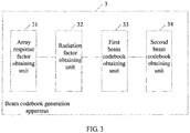
- FIG. 3 is a schematic diagram of structural composition of a first embodiment of a beam codebook generation apparatus applicable to implementation of the method embodiment of the present invention according to the present invention.
- the beam codebook generation apparatus 3 of the present invention may include an array response factor obtaining unit 31, a radiation factor obtaining unit 32, a first beam codebook obtaining unit 33, and a second beam codebook obtaining unit 34, where
- the beam codebook generation apparatus of the present invention further includes a setting unit, which is configured to set the number of the target beam signal channels and the sequence number of the reference beam.
- the beam signal channels in the present invention may be antenna array element channels or filter channels or other beam signal channels that are formed by other devices capable of generating beam channels, and an antenna array element may be an antenna array element formed of phased array antennas.
- an antenna array element may be an antenna array element formed of phased array antennas.
- the number of the beam signal channels may be the number of antenna array elements.
- the value of the number of the target beam signal channels, which is set in the present invention may be less than or equal to the number of the actually generated beam signal channels.
- the number of antenna array elements as an example for description, and assuming that the number of actual antenna array elements is M (M is a positive integer) and the set number of the target antenna array elements is m (m is a positive integer), in some feasible embodiments, m and M may satisfy a condition: m ⁇ M.
- the number of the target beams corresponds to the set number of the target beam signal channels.
- the number of the target beams may be less than or equal to twice of the number of the target beam signal channels
- the sequence number of the reference beam in the target beams may be less than or equal to the number of the target beam signal channels.
- the number of the actual antenna array elements is M (M is a positive integer)
- the number of the target antenna array elements is m (m is a positive integer)
- the number of the target beams are K (K is a positive integer)
- the sequence number of the reference beam is i, in some feasible embodiments, K ⁇ 2m and i ⁇ m.
- i is the sequence number of the reference beam (as described above, in some feasible embodiments, i may satisfy: i ⁇ m), W i is an array weighted vector of the reference beam in a beam codebook matrix, H and * indicate conjugate transpose and conjugate respectively, p is a sequence number of an actually generated beam signal channel, where values of p are 0, 1,..., M-1 successively, M is the number of the actually generated beam signal channels, m is the set number of the target beam signal channels (as described above, in some feasible embodiments, m may satisfy: m ⁇ M), ⁇ is an angle of direction of arrival, a( ⁇ ) is a steering vector of a received signal, and d and ⁇ are array element spacing and a carrier wavelength respectively.
- W p,i may be obtained according to formula (1) or another known array weighted vector calculation method, which is not detailed here.
- i is the sequence number of the reference beam (as described above, in some feasible embodiments, i may satisfy: i ⁇ m), W i is the array weighted vector of the reference beam in the beam codebook matrix, H and * indicate conjugate transpose and conjugate respectively, q is a sequence number of a target beam signal channel, where values of q are 0, 1,..., m-1 successively, m is the set number of the target beam signal channels (as described above, in some feasible embodiments, m may satisfy: m ⁇ M), ⁇ is the angle of direction of arrival, a( ⁇ ) is the steering vector of the received signal, and d and ⁇ are the array element spacing and the carrier wavelength respectively.
- W q,i may be obtained according to formula (1) or another known array weighted vector calculation method, which is not detailed here.
- a method for performing radiated power normalization processing on the first array response factor by the radiation factor obtaining unit 32 to obtain a first radiation factor of the reference beam may be expressed by formula (4):
- G i M m ⁇ AF i M m ⁇ 2 m ⁇ ⁇ ⁇ AF i M m ⁇ 2 d ⁇
- i is the sequence number of the reference beam (as described above, in some feasible embodiments, i may satisfy: i ⁇ m), AF i M m is the first array response factor of the reference beam, m is the set number of the target beam signal channels (as described above, in some feasible embodiments, m may satisfy: m ⁇ M), ⁇ is the angle of direction of arrival, and d is the array element spacing expressed by the carrier wavelength.
- i is the sequence number of the reference beam (as described above, in some feasible embodiments, i may satisfy: i ⁇ m), AF i m is the second array response factor of the reference beam, m is the set number of the target beam signal channels (as described above, in some feasible embodiments, m may satisfy: m ⁇ M), ⁇ is the angle of direction of arrival, and d is the array element spacing expressed by the carrier wavelength.
- i is the sequence number of the reference beam (as described above, in some feasible embodiments, i may satisfy: i ⁇ m), M is the number of the actually generated beam signal channels, m is the set number of the target beam signal channels (as described above, in some feasible embodiments, m may satisfy: m ⁇ M), p is the sequence number of the actually generated beam signal channel, where values of p are 0, 1,..., M-1 successively, G i m is the second radiation factor of the reference beam, G i (M, m ) is the first radiation factor of the reference beam, ⁇ is the angle of direction of arrival, d is the array element spacing expressed by the carrier wavelength, and
- 1 indicates the phase control condition, that is, the beam codebook performs only phase rotation for a signal without performing amplitude adjustment.
- i is the sequence number of the reference beam (as described above, in some feasible embodiments, i may satisfy: i ⁇ m), M is the number of the actually generated beam signal channels, m is the set number of the target beam signal channels (as described above, in some feasible embodiments, m may satisfy: m ⁇ M), p is the sequence number of the actually generated beam signal channel, where values of p are 0, 1,..., M-1 successively, G i m is the second radiation factor of the reference beam, G i ( M , m ) is the first radiation factor of the reference beam, ⁇ is the angle of direction of arrival, d is the array element spacing expressed by the carrier wavelength, and
- 1 indicates a phase control condition, that is, the beam codebook performs only phase rotation for a signal without performing amplitude adjustment.
- i is the sequence number of the reference beam (as described above, in some feasible embodiments, i may satisfy: i ⁇ m), M is the number of the actually generated beam signal channels, m is the set number of the target beam signal channels (as described above, in some feasible embodiments, m may satisfy: m ⁇ M), p is the sequence number of the actually generated beam signal channel, where values of p are 0, 1,..., M-1 successively, G i m is the second radiation factor of the reference beam, G i ( M , m ) is the first radiation factor of the reference beam, ⁇ is the angle of direction of arrival, and d is the array element spacing expressed by the carrier wavelength.
- p is the sequence number of the actually generated beam signal channel
- i is the sequence number of the reference beam (as described above, in some feasible embodiments, i may satisfy: i ⁇ m)
- M is the number of the actually generated beam signal channels
- m is the set number of the target beam signal channels (as described above, in some feasible embodiments, m may satisfy: m ⁇ M)
- K is the number of the target beams (as described above, in some feasible embodiments, K may satisfy: K ⁇ 2m)
- r is the sequence number of the target beam
- values of p are 0, 1,..., M-1 successively
- values of r are 0, 1,..., i-1, i+1,..., K-1 successively
- angle( w p , i ) is a phase value of the beam codebook of the reference beam.
- calculated beam codebooks of all the K target beams may form a codebook matrix W (M,m) .
- FIG. 4 is a schematic diagram of structural composition of a first embodiment of a beam search apparatus 4 applicable to implementation of the method embodiment of the present invention according to the present invention.
- the beam search apparatus 4 of the present invention may include a setting unit 41, a searching unit 42, and a controlling unit 43, where:
- the beam codebook generation method and apparatus of the present invention may be used to obtain:
- the searching unit 42 uses beam codebooks W (M,4) , W( M,8 ),..., W( M,M/2 ) as a beam search condition successively for performing beam search.
- FIG. 5 is a schematic diagram of structural composition of a first embodiment of a beam search system 5 according to the present invention.
- the beam search system 5 of the present invention may include the beam codebook generation apparatus 3 of the present invention and the beam codebook search apparatus 4 of the present invention, where structures and features of the beam codebook generation apparatus 3 and the beam codebook search apparatus 4 are the same as those described in the foregoing embodiments and are not described repeatedly here.
- the number of target beam signal channels is set, and a beam codebook is calculated based on the number of actually generated beam signal channels and the set number of the target beam signal channels, where the beam codebook is generated under a circumstance of the number of the actually generated beam signal channels, where the circumstance is equivalent to a circumstance of the number of the target beam signal channels, so that when beam search is performed by using the generated beam codebook, all actual beam signal channels may be used, and it is unnecessary to perform activation and deactivation control on a single beam signal channel, which reduces hardware implementation difficulty.
- the present invention further provides a computer storage medium, where the computer storage medium may store a program, and, when the program is executed, some or all of the steps of each embodiment of the beam codebook generation method provided in the present invention may be performed.
- the present invention further provides a computer storage medium, where the computer storage medium may store a program, and, when the program is executed, some or all of the steps of each embodiment of the beam codebook search method provided in the present invention may be performed.
- the present invention further provides a network device 6, which may include: an input apparatus 61, an output apparatus 62, a memory 63, and a processor 64 (in specific implementation, there may be multiple processors 64 of the network device 6, and only one processor is given in FIG. 6 as an example for description).
- a network device 6 may include: an input apparatus 61, an output apparatus 62, a memory 63, and a processor 64 (in specific implementation, there may be multiple processors 64 of the network device 6, and only one processor is given in FIG. 6 as an example for description).
- the input apparatus 61, the output apparatus 62, the memory 63, and the processor 64 may be connected by using a bus or by other manners, and bus connection is used as an example in FIG. 6 .
- the processor 64 may perform the following steps:
- the memory 63 stores information such as the number of the target beam signal channels and the sequence number of the reference beam, which need to be used by the processor 64. In some feasible embodiments, a value of the number of the target beam signal channels is less than or equal to the number of the actually generated beam signal channels, and the sequence number of the reference beam in the target beams is less than or equal to the number of the target beam signal channels.
- i is the sequence number of the reference beam (as described above, in some feasible embodiments, i may satisfy: i ⁇ m), W i is an array weighted vector of the reference beam in a beam codebook matrix, H and * indicate conjugate transpose and conjugate respectively, p is a sequence number of an actually generated beam signal channel, where values of p are 0, 1,..., M-1 successively, M is the number of the actually generated beam signal channels, m is the set number of the target beam signal channels (as described above, in some feasible embodiments, m may satisfy: m ⁇ M), ⁇ is an angle of direction of arrival, a( ⁇ ) is a steering vector of a received signal, and d and ⁇ are array element spacing and a carrier wavelength respectively.
- W p,i may be obtained according to formula (1) or another known array weighted vector calculation method, which is not detailed here.
- i is the sequence number of the reference beam (as described above, in some feasible embodiments, i may satisfy: i ⁇ m), W i is the array weighted vector of the reference beam in the beam codebook matrix, H and * indicate conjugate transpose and conjugate respectively, q is a sequence number of a target beam signal channel, where values of q are 0, 1,..., m-1 successively, m is the set number of the target beam signal channels (as described above, in some feasible embodiments, m may satisfy: m ⁇ M), ⁇ is the angle of direction of arrival, a( ⁇ ) is the steering vector of the received signal, and d and ⁇ are the array element spacing and the carrier wavelength respectively.
- W p,i may be obtained according to formula (1) or another known array weighted vector calculation method, which is not detailed here.
- i is the sequence number of the reference beam (as described above, in some feasible embodiments, i may satisfy: i ⁇ m), AF i M m is the first array response factor of the reference beam, m is the set number of the target beam signal channels (as described above, in some feasible embodiments, m may satisfy: m ⁇ M), ⁇ is the angle of direction of arrival, and d is the array element spacing expressed by the carrier wavelength.
- i is the sequence number of the reference beam (as described above, in some feasible embodiments, i may satisfy: i ⁇ m), AF i m is the second array response factor of the reference beam, m is the set number of the target beam signal channels (as described above, in some feasible embodiments, m may satisfy: m ⁇ M), ⁇ is the angle of direction of arrival, and d is the array element spacing expressed by the carrier wavelength.
- i is the sequence number of the reference beam (as described above, in some feasible embodiments, i may satisfy: i ⁇ m), M is the number of the actually generated beam signal channels, m is the set number of the target beam signal channels (as described above, in some feasible embodiments, m may satisfy: m ⁇ M), p is the sequence number of the actually generated beam signal channel, where values of p are 0, 1,..., M-1 successively, G i m is the second radiation factor of the reference beam, G i ( M , m ) is the first radiation factor of the reference beam, ⁇ is the angle of direction of arrival, d is the array element spacing expressed by the carrier wavelength, and
- 1 indicates the phase control condition, that is, the beam codebook performs only phase rotation for a signal without performing amplitude adjustment.
- i is the sequence number of the reference beam (as described above, in some feasible embodiments, i may satisfy: i ⁇ m), M is the number of the actually generated beam signal channels, m is the set number of the target beam signal channels (as described above, in some feasible embodiments, m may satisfy: m ⁇ M), p is the sequence number of the actually generated beam signal channel, where values of p are 0, 1,..., M-1 successively, G i m is the second radiation factor of the reference beam, G i ( M , m ) is the first radiation factor of the reference beam, ⁇ is the angle of direction of arrival, d is the array element spacing expressed by the carrier wavelength, and
- 1 indicates a phase control condition, that is, the beam codebook performs only phase rotation for a signal without performing amplitude adjustment.
- i is the sequence number of the reference beam (as described above, in some feasible embodiments, i may satisfy: i ⁇ m), M is the number of the actually generated beam signal channels, m is the set number of the target beam signal channels (as described above, in some feasible embodiments, m may satisfy: m ⁇ M), p is the sequence number of the actually generated beam signal channel, where values of p are 0, 1,..., M-1 successively, G i m is the second radiation factor of the reference beam, G i ( M , m ) is the first radiation factor of the reference beam, ⁇ is the angle of direction of arrival, and d is the array element spacing expressed by the carrier wavelength.
- p is the sequence number of the actually generated beam signal channel
- i is the sequence number of the reference beam (as described above, in some feasible embodiments, i may satisfy: i ⁇ m)
- M is the number of the actually generated beam signal channels
- m is the set number of the target beam signal channels (as described above, in some feasible embodiments, m may satisfy: m ⁇ M)
- K is the number of the target beams (as described above, in some feasible embodiments, K may satisfy: K ⁇ 2m)
- r is the sequence number of the target beam
- values of p are 0, 1,..., M-1 successively
- values of r are 0, 1,..., i-1, i+1,..., K-1 successively
- angle( w p , i ) is a phase value of the beam codebook of the reference beam.
- a network device 6 sets the number of target beam signal channels, and calculates a beam codebook based on the number of actually generated beam signal channels and the set number of the target beam signal channels, where the beam codebook is generated under a circumstance of the number of the actually generated beam signal channels, where the circumstance is equivalent to a circumstance of the number of the target beam signal channels, so that when beam search is performed by using the generated beam codebook, all actual beam signal channels may be used, and it is unnecessary to perform activation and deactivation control on a single beam signal channel, which reduces hardware implementation difficulty.
- the present invention further provides a network device 7, which may include: an input apparatus 71, an output apparatus 72, a memory 73, and a processor 74 (in specific implementation, the processors 74 of the network device 7 may be plural, and only one processor is given in FIG. 7 as an example for description).
- a network device 7 may include: an input apparatus 71, an output apparatus 72, a memory 73, and a processor 74 (in specific implementation, the processors 74 of the network device 7 may be plural, and only one processor is given in FIG. 7 as an example for description).
- the input apparatus 71, the output apparatus 72, the memory 73, and the processor 74 may be connected by using a bus or by other manners, and bus connection is used as an example in FIG. 7 .
- the processor 74 may perform the following steps:
- step (2) beam codebooks W (M,4) , W( M,8 ),..., W (M,M/2) are used successively as a beam search condition for performing beam search.
Landscapes
- Engineering & Computer Science (AREA)
- Computer Networks & Wireless Communication (AREA)
- Signal Processing (AREA)
- Physics & Mathematics (AREA)
- Mathematical Physics (AREA)
- Power Engineering (AREA)
- Variable-Direction Aerials And Aerial Arrays (AREA)
- Radio Transmission System (AREA)
Description
- The present invention relates to the communications field, and in particular, to a beam codebook generation method, a beam search method, and related apparatuses.
- In a beamforming system, at a transmit end, after being multiplied by a transmitting weight vector w, transmitted signals are transmitted to a radio channel by using different antenna array elements; and, at a receive end, received signals of the antenna array elements are transmitted to a signal processing module after weighted vector summation of a receiving weight c is performed. Forming of a target beam is categorized into an adaptive beamforming technology and a beam switching technology. The adaptive beamforming technology is to obtain an optimal beam mode after a series of operations, that is, an antenna weighted vector w, are performed on a signal received by an array antenna, and use the optimal beam mode for communication. Although the adaptive beamforming may be optimal in theory, its computing complexity is high and its convergence speed is slow. Therefore, a beam switching technology is introduced in order to reduce implementation difficulty. The beam switching technology refers to forming a beam codebook matrix W=(w0,w1,...,wK) after the antenna weighted vector w required for beamforming is predefined and has a fixed value in a device, so that the device only needs to search for the weighted vector in beam codebook space during practical communication. Currently, the beam switching technology is widely applied in millimetric wave communications. All 60 GHz millimetric wave communications standards (IEEE802.15.3c, IEEE802.11ad, Chinese standards, and the like), which are currently released or under development, support the beam switching technology that is based on a fixed beam codebook.
- The currently released standard IEEE802.15.3c stipulates the beam codebook matrix W. Formula (1) is a formula for generating an element in a pth row and a qth column in the IEEE802.15.3c codebook matrix W, that is, a pth-dimension element in a codebook vector wq of a qth beam, where M is the number of the antenna array elements, K is the number of beams (K ≥ M, generally K = 2M). Formula (1) denotes an N-phase codebook, where the codebook may use more fine-grained phases to generate a beam that has a higher main lobe gain and a lower side lobe level. In the formula, N is the number of phases.

- In a case in which the beam codebook is known (in a case in which formula (1) is known), the device can, during practical communication, obtain a sufficient antenna gain simply by searching for an optimal beam pair in a specific manner.
- To improve beam search efficiency and reduce time consumption and energy consumption in a beam search process, a fast beam search algorithm is submitted to related Chinese 60 GHz millimetric wave communications standards. The algorithm first creates a model of a beam search issue by treating it as an optimization issue, and then uses sequence numbers of beams of both the transmit and receive ends as independent variables and uses strength or a signal-to-noise ratio of a received signal as a target function to obtain optimized search space. The fast beam search algorithm takes advantage of beam width difference generated by different numbers of the antenna array elements, and accelerates the beam search process based on a dichotomic search idea and a dichotomy policy. A currently used basic process of the fast beam search algorithm is as follows:
- (a) Set the number of activated antenna array elements to m = 2 and deactivate the remaining M-2 antenna array elements, perform beam search (in this case, the beams are relatively wide, the search space is relatively small, and a traverse method may be used) to obtain a current optimal beam pair, record a main lobe direction (f, ϕ) of an optimal beam, and record a search counter as i = 1.
- (b) Set i = i + 1, set the number of activated antenna array elements to m = 2i and set the number of deactivated antenna array elements to M-2i, use beams close to the currently recorded optimal main lobe direction (f, ϕ) as an initial beam pair to continue the beam search and obtain an optimal beam pair, and update the record of the main lobe direction (f, ϕ) of the optimal beam.
- (c) If all antenna array elements are put into use (m = M), end the search and use the currently recorded optimal beam pair as a final search result; otherwise, return to step (b).
- It can be learnt from the foregoing description that, when the beam codebook is calculated by using formula (1) currently, in order to implement beam search, activation and deactivation control needs to be performed separately on each antenna array element of a phased array antenna until all antenna array elements are in an activated state, which undoubtedly increases hardware implementation difficulty and is adverse to algorithm implementation.
- Document "Low Complexity Codebook-Based Beamforming for MIMO-OFDM Systems in Millimeter-Wave WPAN" (IEEE Transactions on Wireless Communications, Vol.10, no.ll, 1 November 2011, pages 3607-3612 XP011389721) discloses a beamforming system in millimeter-wave wireless personal area networks (WPAN), where transmit and receive weight vectors are jointly derived by exchanging a training sequence repeatedly with different combinations of transmit and receive weight vectors, and a low complexity codebook-based beamforming scheme that consists of multiple levels and level-adaptive antenna selection in order to reduce the beamforming setup time. For each level, 1) the transmit and receive antennas are selected according to pre-determined inter-element spacings, 2) the training sequences are sent with different weight vectors from a pre-defined codebook and 3) the receiver selects the best transmit and receive weight vectors in order to optimize an effective signal-to-noise ratio (SNR) and these vectors are used to determine the codebook for the next following level. Even with low complexity, we show from the numerical results that our proposed scheme can provide an effective SNR gain and an average spectral efficiency approaching those of the codebook-based beamforming with exhaustive search.
- Document "Multilevel millimeter wave beamforming for wireless backhaul" (GLOBECOM Workshops (GC Wkshps), 2011 IEEE, IEEE, 5 December 2011, pages 253-257 XP032124588) discloses a beam searching algorithm and a codebook design for multilevel beamforming in outdoor millimeter wave communication systems. In an outdoor millimeter wave scenario, the received signal suffers from severe path loss and various attenuation factors. Beamforming is an essential component to establish the wireless link in 60GHz up to 80GHz. A millimeter wave beamforming method based on joint transmitter-receiver searching of an adaptive codebook is described. To reduce search complexity, an adaptive beam width beamforming technique is developed based on a sub-array method using squinting angles. A multilevel codebook having a hierarchical tree-structure on different beam width is adaptively designed.
- Embodiments of the present invention provide a beam codebook generation method, a beam codebook generation apparatus, so that when beam search is performed by using a generated beam codebook, all beam signal channels may be used and hardware implementation difficulty is reduced.
- A first aspect of the present invention provides a beam codebook generation method, according to claim 1. A second aspect of the present invention provides a beam codebook generation apparatus according to claim 2.
- It can be learned from the foregoing description that, in feasible implementation manners of the present invention, the number of target beam signal channels is set, and a beam codebook is calculated based on the number of actually generated beam signal channels and the set number of the target beam signal channels, where the beam codebook is generated under a circumstance of the number of the actually generated beam signal channels, where the circumstance is equivalent to a circumstance of the number of the target beam signal channels, so that when beam search is performed by using the generated beam codebook, all actual beam signal channels may be used, and it is unnecessary to perform activation and deactivation control on a single beam signal channel, which reduces hardware implementation difficulty.
-
-
FIG. 1 is a schematic flowchart of a first embodiment of a beam codebook generation method according to the present invention; -
FIG. 2 is a schematic flowchart of a first embodiment of a beam search method according to the present invention; -
FIG. 3 is a schematic diagram of structural composition of a first embodiment of a beam codebook generation apparatus according to the present invention; -
FIG. 4 is a schematic diagram of structural composition of a first embodiment of a beam search apparatus according to the present invention; -
FIG. 5 is a schematic diagram of structural composition of a first embodiment of a beam search system according to the present invention; -
FIG. 6 is a schematic diagram of structural composition of an embodiment of a network device according to the present invention; and -
FIG. 7 is a schematic diagram of structural composition of an embodiment of a network device according to the present invention. - To make objectives, technical solutions and advantages of the present invention clearer, the following describes the present invention in more detail with reference to accompanying drawings.
- In some feasible implementation manners of the present invention, the number of target beam signal channels is set, and a beam codebook is calculated based on the number of actually generated beam signal channels and the set number of the target beam signal channels, where the beam codebook is generated under a circumstance of the number of the actually generated beam signal channels, where the circumstance is equivalent to a circumstance of the number of the target beam signal channels, so that when beam search is performed by using the generated beam codebook, all actual beam signal channels may be used, and it is unnecessary to perform activation and deactivation control on a single beam signal channel, which reduces hardware implementation difficulty.
-
FIG. 1 is a schematic flowchart of a first embodiment of a beam codebook generation method according to the present invention. As shown inFIG. 1 , the beam codebook generation method of the present invention may include the following steps: - Step S110: Calculate a first array response factor of a reference beam with a specified sequence number in target beams according to the number of actually generated beam signal channels, and calculate a second array response factor of the reference beam in the target beams according to the preset number of target beam signal channels, where the array response factor is a weighted value assigned by a system to each beam signal channel.
- In some feasible embodiments, actual beam signal channels in the present invention may be antenna array element channels or filter channels or other beam signal channels that are formed by other devices capable of generating beam channels, and an antenna array element may be an antenna array element formed of phased array antennas. When beam signal channels are antenna array element channels, the number of the beam signal channels may be the number of antenna array elements. In this case, the array response factor is a weighted value assigned by the system to each antenna array element. The number of the actually generated beam signal channels is the number of beam signal channels that can be actually generated by the foregoing devices capable of generating beam channels, and the number of the target beam signal channels is the number of beam signal channels expected to be generated by the devices capable of generating beam channels.
- In some feasible embodiments, the value of the number of the target beam signal channels, which is set in the present invention, may be less than or equal to the number of the actually generated beam signal channels. For example, using the number of antenna array elements as an example for description, and assuming that the number of actual antenna array elements is M (M is a positive integer) and the set number of the target antenna array elements is m (m is a positive integer), in some feasible embodiments, m and M may satisfy a condition: m < M.
- In some feasible embodiments, the number of the target beams corresponds to the set number of the target beam signal channels. Generally, the number of the target beams may be less than or equal to twice of the number of the target beam signal channels, and the sequence number of the reference beam in the target beams may be less than or equal to the number of the target beam signal channels. For example, description is given by using an example in which the number of the actual antenna array elements is M (M is a positive integer), the number of the target antenna array elements is m (m is a positive integer), the number of the target beams are K (K is a positive integer), and the sequence number of the reference beam is i, in some feasible embodiments, K ≤ 2m and i ≤ m.
- In some feasible embodiments, a method for calculating the first array response factor of the reference beam in the target beams according to the number of the actually generated beam signal channels may be expressed by formula (2):

- In formula (2), i is the sequence number of the reference beam (as described above, in some feasible embodiments, i may satisfy: i ≤ m), Wi is an array weighted vector of the reference beam in a beam codebook matrix, H and * indicate conjugate transpose and conjugate respectively, p is a sequence number of an actually generated beam signal channel, where values of p are 0, 1,..., M-1 successively, M is the number of the actually generated beam signal channels, m is the set number of the target beam signal channels (as described above, in some feasible embodiments, m may satisfy: m < M), θ is an angle of direction of arrival, a(θ) is a steering vector of a received signal, and d and λ are array element spacing and a carrier wavelength respectively.
- In some feasible embodiments, Wp,i may be obtained according to formula (1) or another known array weighted vector calculation method, which is not detailed here.
- In some feasible embodiments, a method for calculating the second array response factor of the reference beam in the target beams according to the number of the actually generated beam signal channels may be expressed by formula (3):

- In formula (3), i is the sequence number of the reference beam (as described above, in some feasible embodiments, i may satisfy: i ≤ m), Wi is the array weighted vector of the reference beam in the beam codebook matrix, H and * indicate conjugate transpose and conjugate respectively, q is a sequence number of a target beam signal channel, where values of q are 0, 1,..., m-1 successively, m is the set number of the target beam signal channels (as described above, in some feasible embodiments, m may satisfy: m < M), θ is the angle of direction of arrival, a(θ) is the steering vector of the received signal, and d and λ are the array element spacing and the carrier wavelength respectively.
- In some feasible embodiments, Wq,i may be obtained according to formula (1) or another known array weighted vector calculation method, which is not detailed here.
- Step S111: Perform radiated power normalization processing on the first array response factor to obtain a first radiation factor of the reference beam, and perform radiated power normalization processing on the second array response factor to obtain a second radiation factor of the reference beam, where the radiation factor is a weighted value assigned to the beam signal when the beam signal channel transmits a signal.
- In some feasible embodiments, a method for performing radiated power normalization processing on the first array response factor to obtain a first radiation factor of the reference beam may be expressed by formula (4):

- In formula (4), i is the sequence number of the reference beam (as described above, in some feasible embodiments, i may satisfy: i ≤ m),

- In some feasible embodiments, a method for performing radiated power normalization processing on the second array response factor to obtain a second radiation factor of the reference beam may be expressed by formula (5):

- In formula (5), i is the sequence number of the reference beam (as described above, in some feasible embodiments, i may satisfy: i ≤ m),

- Step S112: Perform normalization processing on the obtained first radiation factor and second radiation factor of the reference beam to obtain a beam codebook of the reference beam.
- In some feasible embodiments, a method for performing normalization processing on the obtained first radiation factor and second radiation factor of the reference beam to obtain a beam codebook of the reference beam may be expressed by formula (6):

- In formula (6), i is the sequence number of the reference beam (as described above, in some feasible embodiments, i may satisfy: i ≤ m), M is the number of the actually generated beam signal channels, m is the set number of the target beam signal channels (as described above, in some feasible embodiments, m may satisfy: m < M), p is the sequence number of the actually generated beam signal channel, where values of p are 0, 1,..., M-1 successively,

- In some feasible embodiments, a method for performing normalization processing on the obtained first radiation factor and second radiation factor of the reference beam to obtain a beam codebook of the reference beam may be expressed by formula (7):

- In formula (7), i is the sequence number of the reference beam (as described above, in some feasible embodiments, i may satisfy: i ≤ m), M is the number of the actually generated beam signal channels, m is the set number of the target beam signal channels (as described above, in some feasible embodiments, m may satisfy: m < M), p is the sequence number of the actually generated beam signal channel, where values of p are 0, 1,..., M-1 successively,

- In some feasible embodiments, a method for performing normalization processing on the obtained first radiation factor and second radiation factor of the reference beam to obtain a beam codebook of the reference beam may be expressed by formula (8):

- In formula (8), i is the sequence number of the reference beam (as described above, in some feasible embodiments, i may satisfy: i ≤ m), M is the number of the actually generated beam signal channels, m is the set number of the target beam signal channels (as described above, in some feasible embodiments, m may satisfy: m < M), p is the sequence number of the actually generated beam signal channel, where values of p are 0, 1,..., M-1 successively,

- Step S113: Perform rotation processing on the obtained beam codebook of the reference beam to obtain a beam codebook of one or more other beams except the reference beam in the target beams.
- In some feasible embodiments, a method for performing rotation processing on the obtained beam codebook of the reference beam to obtain a beam codebook of one or more other beams except the reference beam in the target beams may be expressed by formula (9):

- In formula (9), p is the sequence number of the actually generated beam signal channel, i is the sequence number of the reference beam (as described above, in some feasible embodiments, i may satisfy: i ≤ m), M is the number of the actually generated beam signal channels, m is the set number of the target beam signal channels (as described above, in some feasible embodiments, m may satisfy: m < M), K is the number of the target beams (as described above, in some feasible embodiments, K may satisfy: K ≤ 2m), r is the sequence number of the target beam, values of p are 0, 1,..., M-1 successively, values of r are 0, 1,..., i-1, i+1,..., K-1 successively, and angle(w p,i ) is a phase value of the beam codebook of the reference beam.
- In specific implementation, after the processing in step S 113 is performed, calculated beam codebooks of all the K target beams may form a codebook matrix W(M,m).
- Table 1 describes a beam codebook W (4,2) when M = 4 and m = 2, and Table 2 and Table 3 describe beam codebooks when M = 8 and m = 2 and m = 4. Table 4 and Table 5 describe codebooks W (16,2) and W (16,4) respectively, and Table 6 describes a phase of a reference beam w 8 (16,8) in a codebook W (16,8). Remaining 15 beams in W (16,8) may be obtained by using a rotation formula (9). Table 7 is a phase table of reference beams w 32 (32,2), w 32 (32,4), w 32 (32,8), and w 32 (32,16) in codebooks W (32,2), W (32,4), W (32,8), and W (32,16), and remaining beams may also be obtained by using a rotation formula (9). Data in the following tables is phase values of components in a weighted vector.
Table 1: Beam codebook phase table W(4,2) when M = 4 and m = 2 angle(w i,m ) w0 (4,2) w1 (4,2) w2 (4,2) w3 (4,2) w 0,m 2.543478 2.543478 2.543478 2.543478 w 1,m 0.666591 2.237387 -2.475 -0.90421 w 2,m -2.47501 0.666584 -2.47501 0.666584 w 3,m -0.59814 -2.16893 2.543457 0.972661 Table 2: Beam codebook phase table W(8.2) when M = 8 and m = 2 angle(w ¡,m ) w0 (8,2) w1 (8,2) w2 (8,2) w3 (8,2) w 0,m -1.71397 -1.71397 -1.71397 -1.71397 w 1,m -0.12566 1.445133 3.01593 -1.69646 w 2,m 2.432319 -0.70927 2.432319 -0.70927 w 3,m -1.57041 -3.1412 1.571186 0.000389 w 4,m 1.571126 1.571126 1.571126 1.571126 w 5,m -0.70925 0.861542 2.432338 -2.28005 w 6,m 3.015939 -0.12565 3.015939 -0.12565 w 7,m 1.427697 -0.1431 -1.7139 2.998494 Table 3: Beam codebook phase table W(8.4) when M = 8 and m = 4 angle(w ¡,m ) w0 (8,4) w1 (8,4) w2 (8,4) w3 (8,4) w4 (8,4) w5 (8,4) w6 (8,4) w7 (8,4) w 0,m 1.097999 1.097999 1.097999 1.097999 1.097999 1.097999 1.097999 1.097999 w 1,m -0.80326 -0.01786 0.767534 1.552932 2.33833 3.123728 -2.37406 -1.58866 w 2,m 2.876721 -1.83567 -0.26487 1.305924 2.876721 -1,83567 -0.26487 1.305924 w 3,m -0.14156 2.214634 -1.71236 0.643838 3.000033 -0.92696 1.429236 -2.49775 w 4,m 3.000031 -0.14156 3.000031 -0.14156 3.000031 -0.14156 3.000031 -0.14156 w 5,m -0.26486 -2.62106 1.305935 -1.05026 2.876731 0.520537 -1.83566 2.091333 w 6,m 2.338348 0.767551 -0.80325 -2.37404 2.338348 0.767551 -0.80325 -2.37404 w 7,m -2.04349 -2.82889 2.668898 1.8835 1.098102 0.312704 -0.47269 -1.25809 Table 4: Beam codebook phase table W(16.2) when M = 16 and m = 2 angle(w i,m ) w0 (16,2) w1 (16,2) w2 (16,2) w3 (16,2) w 0,m 0.004109 0.004109 0.004109 0.004109 w 1,m 1.369535 2.940331 -1.77206 -0.20126 w 2,m -2.58467 0.556918 -2.58467 0.556918 w 3,m -1.238 -2.8088 1.90359 0.332793 w 4,m 1.173554 1.173554 1.173554 1.173554 w 5,m 3.138509 -1.57388 -0.00308 1.567713 w 6,m 0.356941 -2.78465 0.356941 -2.78465 w 7,m -3.13988 1.572512 0.001715 -1.56908 w 8,m -0.12551 -0.12551 -0.12551 -0.12551 w 9,m 3.140859 -1.57153 -0.00073 1.570063 w 10,m 0.001151 -3.14044 0.001151 -3.14044 w 11,m -2.46699 2.245401 0.674605 -0.89619 w 12,m 1.497674 1.497674 1.497674 1.497674 w 13,m -0.13016 1.440635 3.011431 -1.70096 w 14,m -2.38034 0.76125 -2.38034 0.76125 w 15,m 2.32215 0.751353 -0.81944 -2.39024 Table 5: Beam codebook phase table W(16.4) when M = 16 and m = 4 angle(w i,m ) w0 (16,4) w1 (16,4) w2 (16,4) w3 (16,4) w4 (16,4) w5 (16,4) w6 (16,4) w7 (16,4) w 0,m -2.32902 -2.32902 -2.32902 -2.32902 -2.32902 -2.32902 -2.32902 -2.32902 w 1,m -0.72684 0.058557 0.843955 1.629353 2.414752 -3.08304 -2.29764 -1.51224 w 2,m 1.726359 -2.98603 -1.41523 0.155563 1.726359 -2.98603 -1.41523 0.155563 w 3,m -1.83171 0.524482 2.880677 -1.04631 1.30988 -2.61711 -0.26092 2.095279 w 4,m 0.987884 -2.15371 0.987884 -2.15371 0.987884 -2.15371 0.987884 -2.15371 w 5,m -2.70476 1.222226 -1.13397 2.793023 0.436828 -1.91937 2.007625 -0.34857 w 6,m 0.24525 -1.32555 -2.89634 1.816046 0.24525 -1.32555 -2.89634 1.816046 w 7,m -3.12172 2.376065 1.590667 0.805269 0.019871 -0.76553 -1.55093 -2.33632 w 8,m 0.021047 0.021047 0.021047 0.021047 0.021047 0.021047 0.021047 0.021047 w 9,m -2.89678 -2.11139 -1.32599 -0.54059 0.244808 1.030206 1.815604 2.601002 w 10,m 0.436683 2.00748 -2.70491 -1.13411 0.436683 2.00748 -2.70491 -1.13411 w 11,m -2.15356 0.202633 2.558828 -1.36816 0.988032 -2.93896 -0.58276 1.77343 w 12,m 1.309601 -1.83199 1.309601 -1.83199 1.309601 -1.83199 1.309601 -1.83199 w 13,m -1.41545 2.511536 0.155342 -2.20085 1.726138 -0.63006 -2.98625 0.94074 w 14,m 2.41475 0.843953 -0.72684 -2.29764 2.41475 0.843953 -0.72684 -2.29764 w 15,m 0.812296 0.026898 -0.7585 -1.5439 -2.3293 -3.11469 2.383092 1.597694 Table 6: Phase table of a reference beam w8 (16,8) in a beam codebook phase table W(16.8) when M = 16 and m = 8 angle(w i,m ) w8 (16,8) angle(w i,m ) w8 (16,8) w 0,m 1.48566 w 8,m -2.3912 w 1,m 2.35508 w 9,m -2.3933 w 2,m -3.0974 w 10,m -2.4662 w 3,m -2.8503 w 11,m -2.596 w 4,m -2.596 w 12,m -2.8503 w 5,m -2.4662 w 13,m -3.0974 w 6,m -2.3933 w 14,m 2.35508 w 7,m -2.3912 w 15,m 1.48566 Table 7: Phase table of reference beams w32 (32,2), w32 (32,4), w32 (32,8), and w32 (32,16) in W(32,2), W(32,4), W(32,8), and W(32,16) angle(wi , m ) w2 (32,2) w4 (32,4) w8 (32,8) w16 (32,16) angle(w i,m ) w2 (32,2) w4 (32,4) w8 (32,8) w16 (32,16) w 0,m -2.09151 -0.18872 -1.64511 -0.87859 w 16,m -2.98037 -0.46641 0.125402 -2.99875 w 1,m 2.396916 -1.27429 -2.69211 -0.95418 w 17,m -3.12825 -0.43204 0.196097 -2.98562 w 2,m 2.990607 -2.40987 2.613634 -0.9933 w 18,m -1.98384 -0.41108 0.238044 -2.94992 w 3,m 2.759628 -2.38158 2.619001 -1.10009 w 19,m -1.04082 -0.07104 0.36631 -2.90377 w 4,m 1.378956 -3.0853 1.889638 -2.43332 w 20,m -1.48209 -0,01319 0.496438 -2.81305 w 5,m 1.043162 2.339379 1.749315 -2.39316 w 21,m -1.5917 -0.45885 0.626391 -2.74666 w 6,m 0.4486 1.502701 1.518584 -2.48864 w 22,m -1.17638 0.392387 0.898705 -2.65822 w 7,m -0.48749 1.496761 1.255272 -2.51397 w 23,m -1.128 0.409591 1.202516 -2.60438 w 8,m -0.12855 0.409591 1.202516 -2.60438 w 24,m -0.00629 1.496761 1.255272 -2.51397 w 9,m 0.209585 0.392387 0.898705 -2.65822 w 25,m 0.442729 1-502701 1.518584 -2.48864 w 10,m -1.18186 -0.45885 0.626391 -2.74666 w 26,m 2.460706 2.339379 1.749315 -2.39316 w 11,m -2.47411 -0.01319 0.496438 -2.81305 w 27,m -2.20354 -3.0853 1.889638 -2.43332 w 12,m 1.261557 -0.07104 0.36631 -2.90377 w 28,m -1.475 -2.38158 2.619001 -1.10009 w 13,m 1.141712 -0.41108 0.238044 -2.94992 w 29,m -1.09005 -2.40987 2.613634 -0.9933 w 14,m -1.54101 -0.43204 0.196097 -2.98562 w 30,m -0.00539 -1.27429 -2.69211 -0.95418 w 15,m -1.44099 -0.46641 0.125402 -2.99875 w 31,m 0.578074 -0.18872 -1.64511 -0.87859 -
FIG. 2 is a schematic flowchart of a first embodiment of a beam search method according to the present invention. In specific implementation, the beam search method of the present invention performs beam search by using a beam generated according to the foregoing beam codebook generation method of the present invention. It can be learned from the beam codebook generation method of the present invention that, when the number of actually generated beam signal channels is M and the number of target beam signal channels is m, the beam codebook generation method of the present invention may be used to obtain: - W(M,m); when a value of m varies, different beam codebook matrices may be obtained. As shown in
FIG. 2 , the beam search method of the present invention may include the following steps: - Step S210: Perform beam search by using a beam codebook as a beam search condition to obtain a current optimal beam pair, where the beam codebook is calculated when the number of target beam signal channels is 2, record a main lobe direction of an optimal beam, and initialize a search counter to a = 1.
- It can be learned from the beam codebook generation method of the present invention that, in step S210, a beam codebook W(M,2) is used as a beam search condition for performing beam search.
- Step S211: Increase the search counter a with an increment of 1, continue to perform the beam search by using a beam codebook as a beam search condition to obtain a current optimal beam pair, where the beam codebook is calculated when the number of the target beam signal channels is 2a, and record the main lobe direction of the optimal beam.
- Step S212: Determine whether the number of the target beam signal channels is equal to the number of the actually generated beam signal channels; if a result of the determining is yes, end the search and use a current optimal beam pair, which is recorded when the search is ended, as an optimal beam pair; if the result of the determining is no, return to perform step S211.
- It can be learned from the beam codebook generation method of the present invention that, in step S211, beam codebooks W(M,4), W(M,8),..., W(M,M/2) are used successively as a beam search condition for performing beam search.
- To better implement each solution of the method embodiment of the present invention, the embodiments of the present invention further provide related apparatuses.
-
FIG. 3 is a schematic diagram of structural composition of a first embodiment of a beam codebook generation apparatus applicable to implementation of the method embodiment of the present invention according to the present invention. As shown inFIG. 3 , the beamcodebook generation apparatus 3 of the present invention may include an array responsefactor obtaining unit 31, a radiationfactor obtaining unit 32, a first beamcodebook obtaining unit 33, and a second beamcodebook obtaining unit 34, where - the array response
factor obtaining unit 31 is configured to calculate a first array response factor of a reference beam with a specified sequence number in target beams according to the number of actually generated beam signal channels, and calculate a second array response factor of the reference beam in the target beams according to the preset number of target beam signal channels; - the radiation
factor obtaining unit 32 is configured to perform radiated power normalization processing on the first array response factor, which is obtained by the array responsefactor obtaining unit 31, to obtain a first radiation factor of the reference beam, and perform radiated power normalization processing on the second array response factor, which is obtained by the array responsefactor obtaining unit 31, to obtain a second radiation factor of the reference beam; - the first beam
codebook obtaining unit 33 is configured to perform normalization processing on the first radiation factor and the second radiation factor of the reference beam, which are obtained by the radiationfactor obtaining unit 32, to obtain a beam codebook of the reference beam; and - the second beam
codebook obtaining unit 34 is configured to perform rotation processing on the beam codebook of the reference beam to obtain a beam codebook of one or more other beams except the reference beam in the target beams, where the beam codebook of the reference beam is obtained by the first beamcodebook obtaining unit 33. - Optionally, the beam codebook generation apparatus of the present invention further includes a setting unit, which is configured to set the number of the target beam signal channels and the sequence number of the reference beam.
- In some feasible embodiments, the beam signal channels in the present invention may be antenna array element channels or filter channels or other beam signal channels that are formed by other devices capable of generating beam channels, and an antenna array element may be an antenna array element formed of phased array antennas. When beam signal channels are antenna array element channels, the number of the beam signal channels may be the number of antenna array elements.
- In some feasible embodiments, the value of the number of the target beam signal channels, which is set in the present invention, may be less than or equal to the number of the actually generated beam signal channels. For example, using the number of antenna array elements as an example for description, and assuming that the number of actual antenna array elements is M (M is a positive integer) and the set number of the target antenna array elements is m (m is a positive integer), in some feasible embodiments, m and M may satisfy a condition: m < M.
- In some feasible embodiments, the number of the target beams corresponds to the set number of the target beam signal channels. Generally, the number of the target beams may be less than or equal to twice of the number of the target beam signal channels, and the sequence number of the reference beam in the target beams may be less than or equal to the number of the target beam signal channels. For example, description is given by using an example in which the number of the actual antenna array elements is M (M is a positive integer), the number of the target antenna array elements is m (m is a positive integer), the number of the target beams are K (K is a positive integer), and the sequence number of the reference beam is i, in some feasible embodiments, K ≤ 2m and i ≤ m.
- In some feasible embodiments, a method for calculating the first array response factor of the reference beam in the target beams by the array response
factor obtaining unit 31 according to the number of the actually generated beam signal channels may be expressed by formula (2):
- In formula (2), i is the sequence number of the reference beam (as described above, in some feasible embodiments, i may satisfy: i ≤ m), Wi is an array weighted vector of the reference beam in a beam codebook matrix, H and * indicate conjugate transpose and conjugate respectively, p is a sequence number of an actually generated beam signal channel, where values of p are 0, 1,..., M-1 successively, M is the number of the actually generated beam signal channels, m is the set number of the target beam signal channels (as described above, in some feasible embodiments, m may satisfy: m < M), θ is an angle of direction of arrival, a(θ) is a steering vector of a received signal, and d and λ are array element spacing and a carrier wavelength respectively.
- In some feasible embodiments, Wp,i may be obtained according to formula (1) or another known array weighted vector calculation method, which is not detailed here.
- In some feasible embodiments, a method for calculating the second array response factor of the reference beam in the target beams by the array response
factor obtaining unit 31 according to the number of the actually generated beam signal channels may be expressed by formula (3):
- In formula (3), i is the sequence number of the reference beam (as described above, in some feasible embodiments, i may satisfy: i ≤ m), Wi is the array weighted vector of the reference beam in the beam codebook matrix, H and * indicate conjugate transpose and conjugate respectively, q is a sequence number of a target beam signal channel, where values of q are 0, 1,..., m-1 successively, m is the set number of the target beam signal channels (as described above, in some feasible embodiments, m may satisfy: m < M), θ is the angle of direction of arrival, a(θ) is the steering vector of the received signal, and d and λ are the array element spacing and the carrier wavelength respectively.
- In some feasible embodiments, Wq,i may be obtained according to formula (1) or another known array weighted vector calculation method, which is not detailed here.
- In some feasible embodiments, a method for performing radiated power normalization processing on the first array response factor by the radiation
factor obtaining unit 32 to obtain a first radiation factor of the reference beam may be expressed by formula (4):
- In formula (4), i is the sequence number of the reference beam (as described above, in some feasible embodiments, i may satisfy: i ≤ m),

- In some feasible embodiments, a method for performing radiated power normalization processing on the second array response factor by the radiation
factor obtaining unit 32 to obtain a second radiation factor of the reference beam may be expressed by formula (5):
- In formula (5), i is the sequence number of the reference beam (as described above, in some feasible embodiments, i may satisfy: i ≤ m),

- In some feasible embodiments, a method for performing normalization processing on the obtained first radiation factor and second radiation factor of the reference beam by the first beam
codebook obtaining unit 33 to obtain a beam codebook of the reference beam may be expressed by formula (6):
- In formula (6), i is the sequence number of the reference beam (as described above, in some feasible embodiments, i may satisfy: i ≤ m), M is the number of the actually generated beam signal channels, m is the set number of the target beam signal channels (as described above, in some feasible embodiments, m may satisfy: m < M), p is the sequence number of the actually generated beam signal channel, where values of p are 0, 1,..., M-1 successively,

- In some feasible embodiments, a method for performing normalization processing on the obtained first radiation factor and second radiation factor of the reference beam by the first beam
codebook obtaining unit 33 to obtain a beam codebook of the reference beam may be expressed by formula (7):
- In formula (7), i is the sequence number of the reference beam (as described above, in some feasible embodiments, i may satisfy: i ≤ m), M is the number of the actually generated beam signal channels, m is the set number of the target beam signal channels (as described above, in some feasible embodiments, m may satisfy: m < M), p is the sequence number of the actually generated beam signal channel, where values of p are 0, 1,..., M-1 successively,

- In some feasible embodiments, a method for performing normalization processing on the obtained first radiation factor and second radiation factor of the reference beam by the first beam
codebook obtaining unit 33 to obtain a beam codebook of the reference beam may be expressed by formula (8):
- In formula (8), i is the sequence number of the reference beam (as described above, in some feasible embodiments, i may satisfy: i ≤ m), M is the number of the actually generated beam signal channels, m is the set number of the target beam signal channels (as described above, in some feasible embodiments, m may satisfy: m < M), p is the sequence number of the actually generated beam signal channel, where values of p are 0, 1,..., M-1 successively,

- In some feasible embodiments, a method for performing rotation processing on the obtained beam codebook of the reference beam by the second beam
codebook obtaining unit 34 to obtain a beam codebook of one or more other beams except the reference beam in the target beams may be expressed by formula (9):
- In formula (9), p is the sequence number of the actually generated beam signal channel, i is the sequence number of the reference beam (as described above, in some feasible embodiments, i may satisfy: i ≤ m), M is the number of the actually generated beam signal channels, m is the set number of the target beam signal channels (as described above, in some feasible embodiments, m may satisfy: m < M), K is the number of the target beams (as described above, in some feasible embodiments, K may satisfy: K ≤ 2m), r is the sequence number of the target beam, values of p are 0, 1,..., M-1 successively, values of r are 0, 1,..., i-1, i+1,..., K-1 successively, and angle(w p,i ) is a phase value of the beam codebook of the reference beam.
- In specific implementation, after the processing is performed by the beam codebook generation apparatus of the present invention, calculated beam codebooks of all the K target beams may form a codebook matrix W(M,m).
-
FIG. 4 is a schematic diagram of structural composition of a first embodiment of abeam search apparatus 4 applicable to implementation of the method embodiment of the present invention according to the present invention. As shown inFIG. 4 , thebeam search apparatus 4 of the present invention may include asetting unit 41, a searchingunit 42, and a controllingunit 43, where: - the
setting unit 41 is configured to set a search counter and initialize the search counter to a = 1; - the searching
unit 42 is configured to: perform beam search by using a beam codebook as a beam search condition to obtain a current optimal beam pair, where the beam codebook is generated by a beam codebook generation apparatus when the number of target beam signal channels are 2a, where the beam codebook generation apparatus is provided in this embodiment of present invention; and record a main lobe direction of an optimal beam; and - the controlling
unit 43 is configured to: after each time the searchingunit 42 performs the beam search by using the beam codebook as the beam search condition, where the beam codebook is generated when the number of target beam signal channels are 2a, control the settingunit 41 to increase the search counter with an increment of 1, and determine whether the number of the target beam signal channels obtained after the increase of the search counter is equal to the number of actually generated beam signal channels, and, if a result of the determining is yes, instruct the searchingunit 42 to continue to perform the beam search by using the beam codebook as the beam search condition, where the beam codebook is generated when the number of target beam signal channels are 2a, and, if the result of the determining is no, instruct the searchingunit 42 to end the search, and use a current optimal beam pair, which is recorded when the search is ended, as an optimal beam pair. - It can be learned from the beam codebook generation method and apparatus of the present invention that, when the number of actually generated beam signal channels is M and the number of target beam signal channels is m, the beam codebook generation method and apparatus of the present invention may be used to obtain:
- W(M,m); when a value of m varies, different beam codebook matrices may be obtained.
- The searching
unit 42 uses beam codebooks W(M,4), W(M,8),..., W(M,M/2) as a beam search condition successively for performing beam search. -
FIG. 5 is a schematic diagram of structural composition of a first embodiment of abeam search system 5 according to the present invention. As shown inFIG. 5 , thebeam search system 5 of the present invention may include the beamcodebook generation apparatus 3 of the present invention and the beamcodebook search apparatus 4 of the present invention, where structures and features of the beamcodebook generation apparatus 3 and the beamcodebook search apparatus 4 are the same as those described in the foregoing embodiments and are not described repeatedly here. - It can be learned from the foregoing description that, in some feasible implementation manners of the present invention, the number of target beam signal channels is set, and a beam codebook is calculated based on the number of actually generated beam signal channels and the set number of the target beam signal channels, where the beam codebook is generated under a circumstance of the number of the actually generated beam signal channels, where the circumstance is equivalent to a circumstance of the number of the target beam signal channels, so that when beam search is performed by using the generated beam codebook, all actual beam signal channels may be used, and it is unnecessary to perform activation and deactivation control on a single beam signal channel, which reduces hardware implementation difficulty.
- In specific implementation, the present invention further provides a computer storage medium, where the computer storage medium may store a program, and, when the program is executed, some or all of the steps of each embodiment of the beam codebook generation method provided in the present invention may be performed.
- In specific implementation, the present invention further provides a computer storage medium, where the computer storage medium may store a program, and, when the program is executed, some or all of the steps of each embodiment of the beam codebook search method provided in the present invention may be performed.
- In specific implementation, as shown in
FIG. 6 , the present invention further provides anetwork device 6, which may include: aninput apparatus 61, anoutput apparatus 62, amemory 63, and a processor 64 (in specific implementation, there may bemultiple processors 64 of thenetwork device 6, and only one processor is given inFIG. 6 as an example for description). - In some feasible embodiments of the present invention, the
input apparatus 61, theoutput apparatus 62, thememory 63, and theprocessor 64 may be connected by using a bus or by other manners, and bus connection is used as an example inFIG. 6 . - In some feasible embodiments of the present invention, the
processor 64 may perform the following steps: - calculating a first array response factor of a reference beam with a specified sequence number in target beams according to the number of actually generated beam signal channels, and calculating a second array response factor of the reference beam in the target beams according to the preset number of target beam signal channels;
- performing radiated power normalization processing on the first array response factor to obtain a first radiation factor of the reference beam, and performing radiated power normalization processing on the second array response factor to obtain a second radiation factor of the reference beam;
- performing normalization processing on the obtained first radiation factor and second radiation factor of the reference beam to obtain a beam codebook of the reference beam; and
- performing rotation processing on the obtained beam codebook of the reference beam to obtain a beam codebook of one or more other beams except the reference beam in the target beams.
- In some feasible embodiments, the
memory 63 stores information such as the number of the target beam signal channels and the sequence number of the reference beam, which need to be used by theprocessor 64. In some feasible embodiments, a value of the number of the target beam signal channels is less than or equal to the number of the actually generated beam signal channels, and the sequence number of the reference beam in the target beams is less than or equal to the number of the target beam signal channels. - In some feasible embodiments, a method for calculating the first array response factor of the reference beam in the target beams by the
processor 64 according to the number of the actually generated beam signal channels may be expressed by formula (2):
- In formula (2), i is the sequence number of the reference beam (as described above, in some feasible embodiments, i may satisfy: i ≤ m), Wi is an array weighted vector of the reference beam in a beam codebook matrix, H and * indicate conjugate transpose and conjugate respectively, p is a sequence number of an actually generated beam signal channel, where values of p are 0, 1,..., M-1 successively, M is the number of the actually generated beam signal channels, m is the set number of the target beam signal channels (as described above, in some feasible embodiments, m may satisfy: m < M), θ is an angle of direction of arrival, a(θ) is a steering vector of a received signal, and d and λ are array element spacing and a carrier wavelength respectively.
- In some feasible embodiments, Wp,i may be obtained according to formula (1) or another known array weighted vector calculation method, which is not detailed here.
- In some feasible embodiments, a method for calculating the second array response factor of the reference beam in the target beams by the
processor 64 according to the number of the actually generated beam signal channels may be expressed by formula (3):
- In formula (3), i is the sequence number of the reference beam (as described above, in some feasible embodiments, i may satisfy: i ≤ m), Wi is the array weighted vector of the reference beam in the beam codebook matrix, H and * indicate conjugate transpose and conjugate respectively, q is a sequence number of a target beam signal channel, where values of q are 0, 1,..., m-1 successively, m is the set number of the target beam signal channels (as described above, in some feasible embodiments, m may satisfy: m < M), θ is the angle of direction of arrival, a(θ) is the steering vector of the received signal, and d and λ are the array element spacing and the carrier wavelength respectively.
- In some feasible embodiments, Wp,i may be obtained according to formula (1) or another known array weighted vector calculation method, which is not detailed here. In some feasible embodiments, a method for performing radiated power normalization processing on the first array response factor by the
processor 64 to obtain a first radiation factor of the reference beam may be expressed by formula (4):
- In formula (4), i is the sequence number of the reference beam (as described above, in some feasible embodiments, i may satisfy: i ≤ m),

- In some feasible embodiments, a method for performing radiated power normalization processing on the second array response factor by the
processor 64 to obtain a second radiation factor of the reference beam may be expressed by formula (5):
- In formula (5), i is the sequence number of the reference beam (as described above, in some feasible embodiments, i may satisfy: i ≤ m),

- In some feasible embodiments, a method for performing normalization processing on the obtained first radiation factor and second radiation factor of the reference beam by the
processor 64 to obtain a beam codebook of the reference beam may be expressed by formula (6):
- In formula (6), i is the sequence number of the reference beam (as described above, in some feasible embodiments, i may satisfy: i ≤ m), M is the number of the actually generated beam signal channels, m is the set number of the target beam signal channels (as described above, in some feasible embodiments, m may satisfy: m < M), p is the sequence number of the actually generated beam signal channel, where values of p are 0, 1,..., M-1 successively,
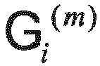
- In some feasible embodiments, a method for performing normalization processing on the obtained first radiation factor and second radiation factor of the reference beam by the
processor 64 to obtain a beam codebook of the reference beam may be expressed by formula (7):
- In formula (7), i is the sequence number of the reference beam (as described above, in some feasible embodiments, i may satisfy: i ≤ m), M is the number of the actually generated beam signal channels, m is the set number of the target beam signal channels (as described above, in some feasible embodiments, m may satisfy: m < M), p is the sequence number of the actually generated beam signal channel, where values of p are 0, 1,..., M-1 successively,

- In some feasible embodiments, a method for performing normalization processing on the obtained first radiation factor and second radiation factor of the reference beam by the
processor 64 to obtain a beam codebook of the reference beam may be expressed by formula (8):
- In formula (8), i is the sequence number of the reference beam (as described above, in some feasible embodiments, i may satisfy: i ≤ m), M is the number of the actually generated beam signal channels, m is the set number of the target beam signal channels (as described above, in some feasible embodiments, m may satisfy: m < M), p is the sequence number of the actually generated beam signal channel, where values of p are 0, 1,..., M-1 successively,

- In some feasible embodiments, a method for performing rotation processing on the obtained beam codebook of the reference beam by the
processor 64 to obtain a beam codebook of one or more other beams except the reference beam in the target beams may be expressed by formula (9):
- In formula (9), p is the sequence number of the actually generated beam signal channel, i is the sequence number of the reference beam (as described above, in some feasible embodiments, i may satisfy: i ≤ m), M is the number of the actually generated beam signal channels, m is the set number of the target beam signal channels (as described above, in some feasible embodiments, m may satisfy: m < M), K is the number of the target beams (as described above, in some feasible embodiments, K may satisfy: K ≤ 2m), r is the sequence number of the target beam, values of p are 0, 1,..., M-1 successively, values of r are 0, 1,..., i-1, i+1,..., K-1 successively, and angle(w p,i ) is a phase value of the beam codebook of the reference beam.
- It can be learned from the foregoing description that, in some feasible implementation manners of the present invention, a
network device 6 sets the number of target beam signal channels, and calculates a beam codebook based on the number of actually generated beam signal channels and the set number of the target beam signal channels, where the beam codebook is generated under a circumstance of the number of the actually generated beam signal channels, where the circumstance is equivalent to a circumstance of the number of the target beam signal channels, so that when beam search is performed by using the generated beam codebook, all actual beam signal channels may be used, and it is unnecessary to perform activation and deactivation control on a single beam signal channel, which reduces hardware implementation difficulty. - In specific implementation, as shown in
FIG. 7 , the present invention further provides anetwork device 7, which may include: aninput apparatus 71, anoutput apparatus 72, amemory 73, and a processor 74 (in specific implementation, theprocessors 74 of thenetwork device 7 may be plural, and only one processor is given inFIG. 7 as an example for description). - In some feasible embodiments of the present invention, the
input apparatus 71, theoutput apparatus 72, thememory 73, and theprocessor 74 may be connected by using a bus or by other manners, and bus connection is used as an example inFIG. 7 . - In some feasible embodiments of the present invention, the
processor 74 may perform the following steps: - (1) performing beam search by using a beam codebook as a beam search condition to obtain a current optimal beam pair, where the beam codebook is calculated when the number of target beam signal channels is 2, recording a main lobe direction of an optimal beam, and initializing a search counter to a = 1; it can be learned from the beam codebook generation method of the present invention that, in this step, a beam codebook W(M,2) is used as a beam search condition for performing beam search;
- (2) increasing the search counter a with an increment of 1, continuing to perform the beam search by using a beam codebook as a beam search condition to obtain a current optimal beam pair, where the beam codebook is calculated when the number of the target beam signal channels is 2a, and recording the main lobe direction of the optimal beam; and
- (3) determining whether the number of the target beam signal channels is equal to the number of actually generated beam signal channels; if a result of the determining is yes, ending the search and using a current optimal beam pair, which is recorded when the search is ended, as an optimal beam pair; if the result of the determining is no, returning to perform step (2).
- It can be learned from the beam codebook generation method of the present invention that, in step (2), beam codebooks W(M,4), W(M,8),..., W(M,M/2) are used successively as a beam search condition for performing beam search.
- It can be learned from the foregoing description that, in some feasible implementation manners of the present invention, when a
network device 7 performs beam search by using a beam codebook generated according to the beam generation method of the present invention, all actual beam signal channels may be used, and it is unnecessary to perform activation and deactivation control on a single beam signal channel, which reduces hardware implementation difficulty.What are enumerated above are merely exemplary embodiments of the present invention, and certainly, are not intended to limit the protection scope of the present invention.
Claims (2)
- A beam codebook generation method, comprising:calculating a first array response factor of a reference beam with a specified sequence number in target beams according to the number of actually generated beam signal channels, and calculating a second array response factor of the reference beam in the target beams according to the preset number of target beam signal channels; wherein the calculating a first array response factor of the reference beam with a specified sequence number in target beams according to the number of actually generated beam signal channels comprises:the calculating a first array response factor of the reference beam in the target beams is according to a formula

i is the sequence number of the reference beam, the calculating a second array response factor of the reference beam in the target beams according to the preset number of target beam signal channels comprises:calculating the second array response factor of the reference beam in the target beams according to a formula
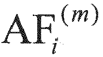 performing radiated power normalization processing on the first array response factor to obtain a first radiation factor of the reference beam, and performing radiated power normalization processing on the second array response factor to obtain a second radiation factor of the reference beam; wherein the performing radiated power normalization processing on the first array response factor to obtain a first radiation factor of the reference beam comprises:calculating the first radiation factor of the reference beam according to a formula
i is the sequence number of the reference beam, Gi (M,m) is a first radiation factor of the reference beam with the sequence number i, the performing radiated power normalization processing on the second array response factor to obtain a second radiation factor of the reference beam comprises:calculating the second radiation factor of the reference beam according to a formula
i is the sequence number of the reference beam,
 calculating the beam codebook of the reference beam according to a formula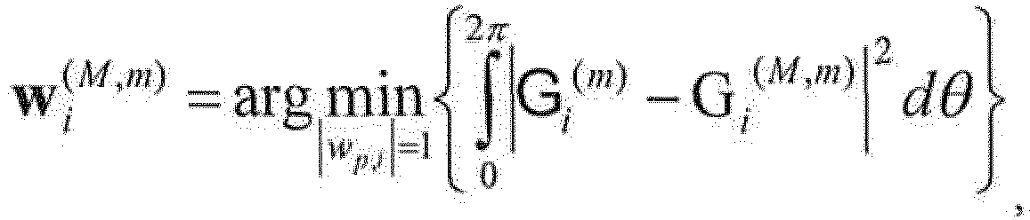
i is the sequence number of the reference beam,
 performing normalization processing on the obtained first radiation factor and second radiation factor of the reference beam to obtain a beam codebook of the reference beam; and performing rotation processing on the obtained beam codebook of the reference beam to obtain a beam codebook of one or more other beams except the reference beam in the target beams, wherein the performing rotation processing on the obtained beam codebook of the reference beam to obtain a beam codebook of one or more other beams except the reference beam in the target beams comprises:calculating the beam codebook of one or more other beams except the reference beam in the target beams according to a formula
- A beam codebook generation apparatus(3), comprising:an array response factor obtaining unit(31), configured to calculate a first array response factor of a reference beam with a specified sequence number in target beams according to the number of actually generated beam signal channels, and calculate a second array response factor of the reference beam in the target beams according to the preset number of target beam signal channels, wherein the array response factor obtaining unit is specifically configured to calculate the first array response factor of the reference beam in the target beams according to a formula

i is the sequence number of the reference beam, the array response factor obtaining unit is specifically configured to: according to a formula
i is the sequence number of the reference beam, a radiation factor obtaining unit(32), configured to perform radiated power normalization processing on the first array response factor, which is obtained by the array response factor obtaining unit, to obtain a first radiation factor of the reference beam, and perform radiated power normalization processing on the second array response factor, which is obtained by the array response factor obtaining unit, to obtain a second radiation factor of the reference beam, wherein the radiation factor obtaining unit is specifically configured to calculate the first radiation factor of the reference beam in the target beams according to a formula
i is the sequence number of the reference beam, Gi (M,m) is a first radiation factor of the reference beam with the sequence number i, the radiation factor obtaining unit is specifically configured to calculate the second radiation factor of the reference beam in the target beams according to a formulaa first beam codebook obtaining unit(33), configured to perform normalization processing on the first radiation factor and the second radiation factor of the reference beam, which are obtained by the radiation factor obtaining unit, to obtain a beam codebook of the reference beam, wherein the first beam codebook obtaining unit is specifically configured to: according to a formula
i is the sequence number of the reference beam,


i is the sequence number of the reference beam,

a second beam codebook obtaining unit(34), configured to perform rotation processing on the beam codebook of the reference beam to obtain a beam codebook of one or more other beams except the reference beam in the target beams, wherein the beam codebook of the reference beam is obtained by the first beam codebook obtaining unit, wherein the second beam codebook obtaining unit is specifically configured to: according to a formula
Applications Claiming Priority (2)
| Application Number | Priority Date | Filing Date | Title |
|---|---|---|---|
| CN201210268457.1A CN102801455B (en) | 2012-07-31 | 2012-07-31 | Wave beam method for generating codebooks, beam search method and relevant apparatus |
| PCT/CN2013/075299 WO2014019392A1 (en) | 2012-07-31 | 2013-05-08 | Beam codebook generation method, beam search method and relevant device |
Publications (3)
| Publication Number | Publication Date |
|---|---|
| EP2874326A1 EP2874326A1 (en) | 2015-05-20 |
| EP2874326A4 EP2874326A4 (en) | 2015-08-19 |
| EP2874326B1 true EP2874326B1 (en) | 2017-01-04 |
Family
ID=47200437
Family Applications (1)
| Application Number | Title | Priority Date | Filing Date |
|---|---|---|---|
| EP13825482.6A Not-in-force EP2874326B1 (en) | 2012-07-31 | 2013-05-08 | Beam codebook generation method, beam search method and relevant device |
Country Status (4)
| Country | Link |
|---|---|
| US (1) | US9160433B2 (en) |
| EP (1) | EP2874326B1 (en) |
| CN (1) | CN102801455B (en) |
| WO (1) | WO2014019392A1 (en) |
Cited By (1)
| Publication number | Priority date | Publication date | Assignee | Title |
|---|---|---|---|---|
| KR101894240B1 (en) * | 2017-04-14 | 2018-09-04 | 한국과학기술원 | Weight determining method for beamforming and weight determining apparatus for beamforming |
Families Citing this family (15)
| Publication number | Priority date | Publication date | Assignee | Title |
|---|---|---|---|---|
| CN103052086B (en) * | 2013-01-22 | 2016-09-07 | 华为技术有限公司 | A kind of millimeter wave phased array beam alignment methods and communication equipment |
| CN104935366B (en) * | 2015-04-21 | 2018-01-02 | 北京航空航天大学 | Beam search method in millimetre-wave attenuator |
| CN107370530B (en) * | 2016-05-12 | 2021-02-12 | 华为技术有限公司 | Channel state information feedback method, precoding method, terminal equipment and base station |
| CN107623540A (en) * | 2016-07-12 | 2018-01-23 | 株式会社Ntt都科摩 | Form method and its device, the base station and mobile station of code book |
| CN107959937B (en) * | 2016-10-17 | 2022-11-22 | 中兴通讯股份有限公司 | Transmission mode determination method, data transmission device and communication system |
| US11082176B2 (en) * | 2016-11-04 | 2021-08-03 | Futurewei Technologies, Inc. | System and method for transmitting a sub-space selection |
| TWI620423B (en) * | 2017-04-28 | 2018-04-01 | 國立清華大學 | Balanced puzzle antenna beam search method for multiple input multiple output operation |
| CN107333290A (en) * | 2017-08-08 | 2017-11-07 | 成都信息工程大学 | A method for monitoring electrical performance parameters of base station antennas |
| CN108320739B (en) * | 2017-12-22 | 2022-03-01 | 景晖 | Method and device for assisting voice instruction recognition according to position information |
| CN111200571B (en) * | 2018-11-19 | 2021-10-01 | 华为技术有限公司 | A kind of signal transmission method and device |
| US11764888B2 (en) | 2019-06-07 | 2023-09-19 | Qualcomm Incorporated | Beam characterization |
| CN113630161B (en) * | 2021-06-21 | 2022-10-18 | 上海移远通信技术股份有限公司 | Method and device for generating beam codebook, electronic equipment and storage medium |
| US12381321B2 (en) | 2021-09-07 | 2025-08-05 | International Business Machines Corporation | Distributed calculation of beamforming parameters for phased arrays |
| US12609741B2 (en) | 2023-07-17 | 2026-04-21 | International Business Machines Corporation | Configurable beamformer integrated circuit control |
| US12580613B2 (en) | 2024-02-06 | 2026-03-17 | International Business Machines Corporation | Arbitrary spatial filters based on beam transformation |
Family Cites Families (15)
| Publication number | Priority date | Publication date | Assignee | Title |
|---|---|---|---|---|
| CN100455075C (en) | 2003-06-05 | 2009-01-21 | 中兴通讯股份有限公司 | Realization device of space multi-beam feeding network |
| US7509346B2 (en) * | 2004-12-29 | 2009-03-24 | Microsoft Corporation | System and method to re-associate class designer shapes to the types they represent |
| US7904117B2 (en) | 2005-08-12 | 2011-03-08 | Sibeam | Wireless communication device using adaptive beamforming |
| US8040278B2 (en) | 2007-11-09 | 2011-10-18 | Intel Corporation | Adaptive antenna beamforming |
| CN101459635B (en) * | 2007-12-14 | 2011-03-16 | 华为技术有限公司 | Method, system and device for enhancing throughput performance of SDMA access system |
| KR101480146B1 (en) * | 2007-12-17 | 2015-01-07 | 한국전자통신연구원 | Method for beamforming |
| CN101527590B (en) | 2008-03-06 | 2013-08-07 | 中兴通讯股份有限公司 | Self-adaptive beam forming method and self-adaptive beam forming device |
| KR101490795B1 (en) | 2008-04-25 | 2015-02-09 | 삼성전자주식회사 | Beamformer and beam forming method |
| US9112562B2 (en) | 2008-09-02 | 2015-08-18 | Intel Corporation | Techniques utilizing adaptive codebooks for beamforming in wireless networks |
| CN102035626B (en) * | 2009-09-30 | 2013-06-12 | 华为技术有限公司 | Method and device for acquiring pre-coding matrix index |
| WO2011150549A1 (en) * | 2010-06-01 | 2011-12-08 | Nokia Corporation | Apparatus and method for selection of beam groups and subset of beams in communication system |
| CN102110883B (en) * | 2010-12-01 | 2013-06-19 | 西安空间无线电技术研究所 | Beam-forming method for forming array antenna of variable beam |
| KR101764261B1 (en) * | 2011-07-15 | 2017-08-04 | 삼성전자주식회사 | Apparatus and method for beam locking in wireless communication system |
| KR20130018079A (en) * | 2011-08-10 | 2013-02-20 | 삼성전자주식회사 | Beam fixing device and method in wireless communication system |
| CN102394680B (en) * | 2011-11-01 | 2014-03-26 | 北京邮电大学 | Beam searching method used in multibeam switching antenna system |
-
2012
- 2012-07-31 CN CN201210268457.1A patent/CN102801455B/en not_active Expired - Fee Related
-
2013
- 2013-05-08 WO PCT/CN2013/075299 patent/WO2014019392A1/en not_active Ceased
- 2013-05-08 EP EP13825482.6A patent/EP2874326B1/en not_active Not-in-force
-
2015
- 2015-01-30 US US14/610,583 patent/US9160433B2/en not_active Expired - Fee Related
Non-Patent Citations (1)
| Title |
|---|
| None * |
Cited By (2)
| Publication number | Priority date | Publication date | Assignee | Title |
|---|---|---|---|---|
| KR101894240B1 (en) * | 2017-04-14 | 2018-09-04 | 한국과학기술원 | Weight determining method for beamforming and weight determining apparatus for beamforming |
| WO2018190495A1 (en) * | 2017-04-14 | 2018-10-18 | 한국과학기술원 | Weight determining method for antenna beamforming and weight determining device for beamforming |
Also Published As
| Publication number | Publication date |
|---|---|
| US9160433B2 (en) | 2015-10-13 |
| US20150171945A1 (en) | 2015-06-18 |
| WO2014019392A1 (en) | 2014-02-06 |
| CN102801455B (en) | 2015-12-16 |
| EP2874326A1 (en) | 2015-05-20 |
| EP2874326A4 (en) | 2015-08-19 |
| CN102801455A (en) | 2012-11-28 |
Similar Documents
| Publication | Publication Date | Title |
|---|---|---|
| EP2874326A1 (en) | Beam codebook generation method, beam search method and relevant device | |
| US10771142B2 (en) | System and method for hierarchal beamforming and rank adaptation for hybrid antenna architecture | |
| US11652535B2 (en) | Beamforming device for antenna arrays | |
| EP3116258B1 (en) | Method for reporting channel state information, user equipment, and base station | |
| Paul et al. | A novel beamspace channel estimation technique for millimeter wave massive MIMO systems | |
| US11652515B2 (en) | Method and device for feeding back channel state information, and method and device for determining channel state information | |
| US11265054B2 (en) | Beamforming method and device | |
| US9155097B2 (en) | Methods and arrangements for beam refinement in a wireless network | |
| EP2253077B1 (en) | Mmwave wpan communication system with fast adaptive beam tracking | |
| EP3408947B1 (en) | Beamforming using an antenna array | |
| EP2246937B1 (en) | Beam shaping method and device | |
| US8571127B2 (en) | MIMO transmission with rank adaptation for multi-gigabit 60 GHz wireless | |
| US8750401B2 (en) | Sequential transmission multi-beamforming method with low complexity using Hadamard matrix | |
| Wu et al. | Two-stage 3D codebook design and beam training for millimeter-wave massive MIMO systems | |
| Singh et al. | Fast beam training for RIS-assisted uplink communication | |
| Wang et al. | Hybrid beamforming under equal gain constraint for maximizing sum rate at 60 GHz | |
| US20240313396A1 (en) | Antenna array with reconfigurable antenna array geometry | |
| CN114726420A (en) | A kind of precoding method, information determination method and device | |
| CN115603781B (en) | Single-user analog beam searching method and device | |
| Almeida et al. | Efficient Channel Estimation for LIS-based Systems | |
| CN109698714B (en) | Array beam detection method and device | |
| Wadhwani et al. | A Review of Smart Antenna System (SAS) with Array Processing Algorithms |
Legal Events
| Date | Code | Title | Description |
|---|---|---|---|
| PUAI | Public reference made under article 153(3) epc to a published international application that has entered the european phase |
Free format text: ORIGINAL CODE: 0009012 |
|
| 17P | Request for examination filed |
Effective date: 20150210 |
|
| AK | Designated contracting states |
Kind code of ref document: A1 Designated state(s): AL AT BE BG CH CY CZ DE DK EE ES FI FR GB GR HR HU IE IS IT LI LT LU LV MC MK MT NL NO PL PT RO RS SE SI SK SM TR |
|
| AX | Request for extension of the european patent |
Extension state: BA ME |
|
| RA4 | Supplementary search report drawn up and despatched (corrected) |
Effective date: 20150722 |
|
| RIC1 | Information provided on ipc code assigned before grant |
Ipc: H04B 7/04 20060101ALI20150716BHEP Ipc: H04L 25/03 20060101ALI20150716BHEP Ipc: H04B 7/06 20060101AFI20150716BHEP |
|
| DAX | Request for extension of the european patent (deleted) | ||
| GRAP | Despatch of communication of intention to grant a patent |
Free format text: ORIGINAL CODE: EPIDOSNIGR1 |
|
| INTG | Intention to grant announced |
Effective date: 20160728 |
|
| GRAS | Grant fee paid |
Free format text: ORIGINAL CODE: EPIDOSNIGR3 |
|
| STAA | Information on the status of an ep patent application or granted ep patent |
Free format text: STATUS: GRANT OF PATENT IS INTENDED |
|
| GRAA | (expected) grant |
Free format text: ORIGINAL CODE: 0009210 |
|
| STAA | Information on the status of an ep patent application or granted ep patent |
Free format text: STATUS: THE PATENT HAS BEEN GRANTED |
|
| AK | Designated contracting states |
Kind code of ref document: B1 Designated state(s): AL AT BE BG CH CY CZ DE DK EE ES FI FR GB GR HR HU IE IS IT LI LT LU LV MC MK MT NL NO PL PT RO RS SE SI SK SM TR |
|
| REG | Reference to a national code |
Ref country code: GB Ref legal event code: FG4D |
|
| REG | Reference to a national code |
Ref country code: CH Ref legal event code: EP |
|
| REG | Reference to a national code |
Ref country code: AT Ref legal event code: REF Ref document number: 860160 Country of ref document: AT Kind code of ref document: T Effective date: 20170115 |
|
| REG | Reference to a national code |
Ref country code: IE Ref legal event code: FG4D |
|
| REG | Reference to a national code |
Ref country code: DE Ref legal event code: R096 Ref document number: 602013016328 Country of ref document: DE |
|
| REG | Reference to a national code |
Ref country code: LT Ref legal event code: MG4D Ref country code: NL Ref legal event code: MP Effective date: 20170104 |
|
| REG | Reference to a national code |
Ref country code: AT Ref legal event code: MK05 Ref document number: 860160 Country of ref document: AT Kind code of ref document: T Effective date: 20170104 |
|
| PG25 | Lapsed in a contracting state [announced via postgrant information from national office to epo] |
Ref country code: NL Free format text: LAPSE BECAUSE OF FAILURE TO SUBMIT A TRANSLATION OF THE DESCRIPTION OR TO PAY THE FEE WITHIN THE PRESCRIBED TIME-LIMIT Effective date: 20170104 |
|
| PG25 | Lapsed in a contracting state [announced via postgrant information from national office to epo] |
Ref country code: FI Free format text: LAPSE BECAUSE OF FAILURE TO SUBMIT A TRANSLATION OF THE DESCRIPTION OR TO PAY THE FEE WITHIN THE PRESCRIBED TIME-LIMIT Effective date: 20170104 Ref country code: HR Free format text: LAPSE BECAUSE OF FAILURE TO SUBMIT A TRANSLATION OF THE DESCRIPTION OR TO PAY THE FEE WITHIN THE PRESCRIBED TIME-LIMIT Effective date: 20170104 Ref country code: NO Free format text: LAPSE BECAUSE OF FAILURE TO SUBMIT A TRANSLATION OF THE DESCRIPTION OR TO PAY THE FEE WITHIN THE PRESCRIBED TIME-LIMIT Effective date: 20170404 Ref country code: GR Free format text: LAPSE BECAUSE OF FAILURE TO SUBMIT A TRANSLATION OF THE DESCRIPTION OR TO PAY THE FEE WITHIN THE PRESCRIBED TIME-LIMIT Effective date: 20170405 Ref country code: IS Free format text: LAPSE BECAUSE OF FAILURE TO SUBMIT A TRANSLATION OF THE DESCRIPTION OR TO PAY THE FEE WITHIN THE PRESCRIBED TIME-LIMIT Effective date: 20170504 Ref country code: LT Free format text: LAPSE BECAUSE OF FAILURE TO SUBMIT A TRANSLATION OF THE DESCRIPTION OR TO PAY THE FEE WITHIN THE PRESCRIBED TIME-LIMIT Effective date: 20170104 |
|
| PG25 | Lapsed in a contracting state [announced via postgrant information from national office to epo] |
Ref country code: SE Free format text: LAPSE BECAUSE OF FAILURE TO SUBMIT A TRANSLATION OF THE DESCRIPTION OR TO PAY THE FEE WITHIN THE PRESCRIBED TIME-LIMIT Effective date: 20170104 Ref country code: PT Free format text: LAPSE BECAUSE OF FAILURE TO SUBMIT A TRANSLATION OF THE DESCRIPTION OR TO PAY THE FEE WITHIN THE PRESCRIBED TIME-LIMIT Effective date: 20170504 Ref country code: LU Free format text: LAPSE BECAUSE OF NON-PAYMENT OF DUE FEES Effective date: 20170531 Ref country code: ES Free format text: LAPSE BECAUSE OF FAILURE TO SUBMIT A TRANSLATION OF THE DESCRIPTION OR TO PAY THE FEE WITHIN THE PRESCRIBED TIME-LIMIT Effective date: 20170104 Ref country code: AT Free format text: LAPSE BECAUSE OF FAILURE TO SUBMIT A TRANSLATION OF THE DESCRIPTION OR TO PAY THE FEE WITHIN THE PRESCRIBED TIME-LIMIT Effective date: 20170104 Ref country code: LV Free format text: LAPSE BECAUSE OF FAILURE TO SUBMIT A TRANSLATION OF THE DESCRIPTION OR TO PAY THE FEE WITHIN THE PRESCRIBED TIME-LIMIT Effective date: 20170104 Ref country code: RS Free format text: LAPSE BECAUSE OF FAILURE TO SUBMIT A TRANSLATION OF THE DESCRIPTION OR TO PAY THE FEE WITHIN THE PRESCRIBED TIME-LIMIT Effective date: 20170104 Ref country code: PL Free format text: LAPSE BECAUSE OF FAILURE TO SUBMIT A TRANSLATION OF THE DESCRIPTION OR TO PAY THE FEE WITHIN THE PRESCRIBED TIME-LIMIT Effective date: 20170104 Ref country code: BG Free format text: LAPSE BECAUSE OF FAILURE TO SUBMIT A TRANSLATION OF THE DESCRIPTION OR TO PAY THE FEE WITHIN THE PRESCRIBED TIME-LIMIT Effective date: 20170404 |
|
| REG | Reference to a national code |
Ref country code: DE Ref legal event code: R097 Ref document number: 602013016328 Country of ref document: DE |
|
| PG25 | Lapsed in a contracting state [announced via postgrant information from national office to epo] |
Ref country code: RO Free format text: LAPSE BECAUSE OF FAILURE TO SUBMIT A TRANSLATION OF THE DESCRIPTION OR TO PAY THE FEE WITHIN THE PRESCRIBED TIME-LIMIT Effective date: 20170104 Ref country code: EE Free format text: LAPSE BECAUSE OF FAILURE TO SUBMIT A TRANSLATION OF THE DESCRIPTION OR TO PAY THE FEE WITHIN THE PRESCRIBED TIME-LIMIT Effective date: 20170104 Ref country code: IT Free format text: LAPSE BECAUSE OF FAILURE TO SUBMIT A TRANSLATION OF THE DESCRIPTION OR TO PAY THE FEE WITHIN THE PRESCRIBED TIME-LIMIT Effective date: 20170104 Ref country code: SK Free format text: LAPSE BECAUSE OF FAILURE TO SUBMIT A TRANSLATION OF THE DESCRIPTION OR TO PAY THE FEE WITHIN THE PRESCRIBED TIME-LIMIT Effective date: 20170104 Ref country code: CZ Free format text: LAPSE BECAUSE OF FAILURE TO SUBMIT A TRANSLATION OF THE DESCRIPTION OR TO PAY THE FEE WITHIN THE PRESCRIBED TIME-LIMIT Effective date: 20170104 |
|
| PLBE | No opposition filed within time limit |
Free format text: ORIGINAL CODE: 0009261 |
|
| STAA | Information on the status of an ep patent application or granted ep patent |
Free format text: STATUS: NO OPPOSITION FILED WITHIN TIME LIMIT |
|
| PG25 | Lapsed in a contracting state [announced via postgrant information from national office to epo] |
Ref country code: SM Free format text: LAPSE BECAUSE OF FAILURE TO SUBMIT A TRANSLATION OF THE DESCRIPTION OR TO PAY THE FEE WITHIN THE PRESCRIBED TIME-LIMIT Effective date: 20170104 Ref country code: DK Free format text: LAPSE BECAUSE OF FAILURE TO SUBMIT A TRANSLATION OF THE DESCRIPTION OR TO PAY THE FEE WITHIN THE PRESCRIBED TIME-LIMIT Effective date: 20170104 |
|
| REG | Reference to a national code |
Ref country code: CH Ref legal event code: PL |
|
| GBPC | Gb: european patent ceased through non-payment of renewal fee |
Effective date: 20170508 |
|
| PG25 | Lapsed in a contracting state [announced via postgrant information from national office to epo] |
Ref country code: MC Free format text: LAPSE BECAUSE OF FAILURE TO SUBMIT A TRANSLATION OF THE DESCRIPTION OR TO PAY THE FEE WITHIN THE PRESCRIBED TIME-LIMIT Effective date: 20170104 |
|
| REG | Reference to a national code |
Ref country code: IE Ref legal event code: MM4A |
|
| PG25 | Lapsed in a contracting state [announced via postgrant information from national office to epo] |
Ref country code: CH Free format text: LAPSE BECAUSE OF NON-PAYMENT OF DUE FEES Effective date: 20170531 Ref country code: LI Free format text: LAPSE BECAUSE OF NON-PAYMENT OF DUE FEES Effective date: 20170531 Ref country code: SI Free format text: LAPSE BECAUSE OF FAILURE TO SUBMIT A TRANSLATION OF THE DESCRIPTION OR TO PAY THE FEE WITHIN THE PRESCRIBED TIME-LIMIT Effective date: 20170104 |
|
| REG | Reference to a national code |
Ref country code: FR Ref legal event code: ST Effective date: 20180131 |
|
| PG25 | Lapsed in a contracting state [announced via postgrant information from national office to epo] |
Ref country code: LU Free format text: LAPSE BECAUSE OF NON-PAYMENT OF DUE FEES Effective date: 20170508 |
|
| REG | Reference to a national code |
Ref country code: BE Ref legal event code: MM Effective date: 20170531 |
|
| PG25 | Lapsed in a contracting state [announced via postgrant information from national office to epo] |
Ref country code: GB Free format text: LAPSE BECAUSE OF NON-PAYMENT OF DUE FEES Effective date: 20170508 Ref country code: IE Free format text: LAPSE BECAUSE OF NON-PAYMENT OF DUE FEES Effective date: 20170508 |
|
| PG25 | Lapsed in a contracting state [announced via postgrant information from national office to epo] |
Ref country code: FR Free format text: LAPSE BECAUSE OF NON-PAYMENT OF DUE FEES Effective date: 20170531 |
|
| PGFP | Annual fee paid to national office [announced via postgrant information from national office to epo] |
Ref country code: DE Payment date: 20180424 Year of fee payment: 6 |
|
| PG25 | Lapsed in a contracting state [announced via postgrant information from national office to epo] |
Ref country code: BE Free format text: LAPSE BECAUSE OF NON-PAYMENT OF DUE FEES Effective date: 20170531 |
|
| PG25 | Lapsed in a contracting state [announced via postgrant information from national office to epo] |
Ref country code: MT Free format text: LAPSE BECAUSE OF NON-PAYMENT OF DUE FEES Effective date: 20170508 |
|
| PG25 | Lapsed in a contracting state [announced via postgrant information from national office to epo] |
Ref country code: HU Free format text: LAPSE BECAUSE OF FAILURE TO SUBMIT A TRANSLATION OF THE DESCRIPTION OR TO PAY THE FEE WITHIN THE PRESCRIBED TIME-LIMIT; INVALID AB INITIO Effective date: 20130508 |
|
| PG25 | Lapsed in a contracting state [announced via postgrant information from national office to epo] |
Ref country code: CY Free format text: LAPSE BECAUSE OF FAILURE TO SUBMIT A TRANSLATION OF THE DESCRIPTION OR TO PAY THE FEE WITHIN THE PRESCRIBED TIME-LIMIT Effective date: 20170104 |
|
| PG25 | Lapsed in a contracting state [announced via postgrant information from national office to epo] |
Ref country code: MK Free format text: LAPSE BECAUSE OF FAILURE TO SUBMIT A TRANSLATION OF THE DESCRIPTION OR TO PAY THE FEE WITHIN THE PRESCRIBED TIME-LIMIT Effective date: 20170104 |
|
| REG | Reference to a national code |
Ref country code: DE Ref legal event code: R119 Ref document number: 602013016328 Country of ref document: DE |
|
| PG25 | Lapsed in a contracting state [announced via postgrant information from national office to epo] |
Ref country code: TR Free format text: LAPSE BECAUSE OF FAILURE TO SUBMIT A TRANSLATION OF THE DESCRIPTION OR TO PAY THE FEE WITHIN THE PRESCRIBED TIME-LIMIT Effective date: 20170104 |
|
| PG25 | Lapsed in a contracting state [announced via postgrant information from national office to epo] |
Ref country code: DE Free format text: LAPSE BECAUSE OF NON-PAYMENT OF DUE FEES Effective date: 20191203 |
|
| PG25 | Lapsed in a contracting state [announced via postgrant information from national office to epo] |
Ref country code: AL Free format text: LAPSE BECAUSE OF FAILURE TO SUBMIT A TRANSLATION OF THE DESCRIPTION OR TO PAY THE FEE WITHIN THE PRESCRIBED TIME-LIMIT Effective date: 20170104 |