EP2874285A2 - Motor - Google Patents
Motor Download PDFInfo
- Publication number
- EP2874285A2 EP2874285A2 EP20140191611 EP14191611A EP2874285A2 EP 2874285 A2 EP2874285 A2 EP 2874285A2 EP 20140191611 EP20140191611 EP 20140191611 EP 14191611 A EP14191611 A EP 14191611A EP 2874285 A2 EP2874285 A2 EP 2874285A2
- Authority
- EP
- European Patent Office
- Prior art keywords
- circuit board
- motor
- fixed
- axially
- region
- Prior art date
- Legal status (The legal status is an assumption and is not a legal conclusion. Google has not performed a legal analysis and makes no representation as to the accuracy of the status listed.)
- Granted
Links
- 238000006243 chemical reaction Methods 0.000 claims abstract description 13
- 239000012212 insulator Substances 0.000 claims description 12
- 210000000078 claw Anatomy 0.000 claims description 7
- 239000003990 capacitor Substances 0.000 claims description 3
- WABPQHHGFIMREM-UHFFFAOYSA-N lead(0) Chemical compound [Pb] WABPQHHGFIMREM-UHFFFAOYSA-N 0.000 claims description 3
- 239000011347 resin Substances 0.000 claims description 2
- 229920005989 resin Polymers 0.000 claims description 2
- 230000009467 reduction Effects 0.000 abstract description 12
- 238000002788 crimping Methods 0.000 description 8
- 230000004048 modification Effects 0.000 description 7
- 238000012986 modification Methods 0.000 description 7
- 238000004519 manufacturing process Methods 0.000 description 4
- 239000002184 metal Substances 0.000 description 4
- 229910052751 metal Inorganic materials 0.000 description 4
- 230000004907 flux Effects 0.000 description 3
- 238000003466 welding Methods 0.000 description 3
- RYGMFSIKBFXOCR-UHFFFAOYSA-N Copper Chemical compound [Cu] RYGMFSIKBFXOCR-UHFFFAOYSA-N 0.000 description 1
- 229910001335 Galvanized steel Inorganic materials 0.000 description 1
- 229910000576 Laminated steel Inorganic materials 0.000 description 1
- 229910000831 Steel Inorganic materials 0.000 description 1
- 239000011248 coating agent Substances 0.000 description 1
- 238000000576 coating method Methods 0.000 description 1
- 238000010411 cooking Methods 0.000 description 1
- 239000011889 copper foil Substances 0.000 description 1
- 239000012530 fluid Substances 0.000 description 1
- 239000008397 galvanized steel Substances 0.000 description 1
- 239000007789 gas Substances 0.000 description 1
- 238000003780 insertion Methods 0.000 description 1
- 230000037431 insertion Effects 0.000 description 1
- 230000003993 interaction Effects 0.000 description 1
- 239000000696 magnetic material Substances 0.000 description 1
- 239000000463 material Substances 0.000 description 1
- 238000000034 method Methods 0.000 description 1
- 238000005476 soldering Methods 0.000 description 1
- 239000010935 stainless steel Substances 0.000 description 1
- 229910001220 stainless steel Inorganic materials 0.000 description 1
- 239000010959 steel Substances 0.000 description 1
Images

Classifications
-
- H—ELECTRICITY
- H02—GENERATION; CONVERSION OR DISTRIBUTION OF ELECTRIC POWER
- H02K—DYNAMO-ELECTRIC MACHINES
- H02K11/00—Structural association of dynamo-electric machines with electric components or with devices for shielding, monitoring or protection
- H02K11/30—Structural association with control circuits or drive circuits
- H02K11/33—Drive circuits, e.g. power electronics
-
- H—ELECTRICITY
- H02—GENERATION; CONVERSION OR DISTRIBUTION OF ELECTRIC POWER
- H02K—DYNAMO-ELECTRIC MACHINES
- H02K5/00—Casings; Enclosures; Supports
- H02K5/04—Casings or enclosures characterised by the shape, form or construction thereof
- H02K5/22—Auxiliary parts of casings not covered by groups H02K5/06-H02K5/20, e.g. shaped to form connection boxes or terminal boxes
-
- H—ELECTRICITY
- H02—GENERATION; CONVERSION OR DISTRIBUTION OF ELECTRIC POWER
- H02K—DYNAMO-ELECTRIC MACHINES
- H02K2203/00—Specific aspects not provided for in the other groups of this subclass relating to the windings
- H02K2203/03—Machines characterised by the wiring boards, i.e. printed circuit boards or similar structures for connecting the winding terminations
-
- H—ELECTRICITY
- H02—GENERATION; CONVERSION OR DISTRIBUTION OF ELECTRIC POWER
- H02K—DYNAMO-ELECTRIC MACHINES
- H02K2211/00—Specific aspects not provided for in the other groups of this subclass relating to measuring or protective devices or electric components
- H02K2211/03—Machines characterised by circuit boards, e.g. pcb
-
- H—ELECTRICITY
- H02—GENERATION; CONVERSION OR DISTRIBUTION OF ELECTRIC POWER
- H02K—DYNAMO-ELECTRIC MACHINES
- H02K3/00—Details of windings
- H02K3/46—Fastening of windings on the stator or rotor structure
- H02K3/52—Fastening salient pole windings or connections thereto
- H02K3/521—Fastening salient pole windings or connections thereto applicable to stators only
-
- H—ELECTRICITY
- H02—GENERATION; CONVERSION OR DISTRIBUTION OF ELECTRIC POWER
- H02K—DYNAMO-ELECTRIC MACHINES
- H02K5/00—Casings; Enclosures; Supports
- H02K5/04—Casings or enclosures characterised by the shape, form or construction thereof
- H02K5/22—Auxiliary parts of casings not covered by groups H02K5/06-H02K5/20, e.g. shaped to form connection boxes or terminal boxes
- H02K5/225—Terminal boxes or connection arrangements
Definitions
- the present invention relates to a motor.
- Household electrical appliances such as hair driers
- AC motors have often been installed in the household electrical appliances.
- use of brushless DC motors in place of the AC motors makes it easier to provide high added value, such as fine rotation control.
- an AC to DC converter arranged to convert an alternating current to a direct current is required. Accordingly, there is an increasing demand for brushless DC motors in which AC to DC converters are installed and which are designed for household electrical appliances.
- a known motor including a converter circuit is described, for example, in JP-A 10-322973 .
- the present invention has been conceived to provide, regarding a motor including a circuit board on which an AC to DC conversion portion is mounted, a structure which is able to achieve a reduction in the radial dimension of the motor while securing a large area in which electronic components can be mounted on the circuit board.
- a brushless DC motor is arranged to convert an alternating current to a direct current and generate a torque with the resulting direct current, and includes a stationary portion fixed to a frame of an apparatus to be driven by the motor through a support member, and a rotating portion arranged to rotate about a central axis extending in a vertical direction relative to the stationary portion.
- the rotating portion includes a shaft arranged along the central axis; a rotor holder including a top plate portion arranged to extend around the shaft, and a cylindrical wall portion arranged to extend axially downward from an outer end portion of the top plate portion; and a magnet fixed to an inner circumferential surface of the wall portion directly or through a yoke.
- the stationary portion includes a bearing portion arranged to rotatably support the shaft; a housing including a cylindrical bearing holding portion arranged to hold the bearing portion; a plurality of coils arranged in a circumferential direction radially outside the housing and radially inside the magnet; an attachment portion fixed to each of the housing and the support member directly or through another member; and a circuit portion electrically connected to the coils.
- the circuit portion includes a plate-shaped first circuit board arranged axially below the coils and axially above the attachment portion, and to which end portions of conducting wires defining the coils are connected; a plate-shaped second circuit board arranged axially below the attachment portion, and arranged to have an AC to DC conversion portion mounted thereon; and an electrical connection portion arranged to electrically connect the first and second circuit boards to each other.
- the first circuit board includes a through hole or a cut defined therein.
- the housing is arranged to extend in the vertical direction through the through hole or the cut.
- the second circuit board includes a first region axially coinciding with the first circuit board; a second region axially coinciding with the through hole or the cut; and a third region axially overlapping with neither the first circuit board nor the through hole or the cut.
- the support member is fixed to the third region.
- two circuit boards are arranged one above the other in an axial direction, and accordingly, a reduction in the radial dimension of the motor is achieved while a large area in which electronic components can be mounted is secured.
- the attachment portion is arranged between the first circuit board and the second circuit board. This leads to an increase in an area in which electronic components can be mounted on the second circuit board, and also leads to a reduction in the axial dimension of the motor.
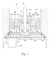
- Fig. 1 is a vertical cross-sectional view of a motor 1A according to a first preferred embodiment of the present invention.
- the motor 1A is a brushless DC motor arranged to convert an alternating current to a direct current and generate a torque with the resulting direct current.
- the motor 1A includes a stationary portion 2A and a rotating portion 3A arranged to rotate about a central axis 9A.
- the stationary portion 2A is fixed to a frame of an apparatus to be driven by the motor 1A through a support member 4A.
- the rotating portion 3A is arranged to rotate relative to the stationary portion 2A.
- the rotating portion 3A includes a shaft 31A, a rotor holder 32A, and a magnet 33A.
- the shaft 31A is arranged along the central axis 9A.
- the rotor holder 32A includes a top plate portion 321A and a wall portion 322A.
- the top plate portion 321A is arranged to extend substantially in the shape of a disk around the shaft 31A.
- the wall portion 322A is substantially cylindrical, and is arranged to extend axially downward from an outer end portion of the top plate portion 321A.
- the magnet 33A is held on an inner circumferential surface of the wall portion 322A directly or through a yoke.
- the stationary portion 2A includes an attachment portion 21A, a housing 22A, bearing portions 23A and 24A, a plurality of coils 53A, and a circuit portion 26A.
- the attachment portion 21A is fixed to each of the housing 22A and the support member 4A directly or through another member.
- the housing 22A includes a substantially cylindrical bearing holding portion 221A. Each of the bearing portions 23A and 24A is held by the bearing holding portion 221A, and is arranged to rotatably support the shaft 31A.
- the coils 53A are arranged in a circumferential direction radially outside the housing 22A and radially inside the magnet 33A.
- the coils 53A are electrically connected to an electrical circuit mounted on the circuit portion 26A.
- the circuit portion 26A includes a plate-shaped first circuit board 61A, a plate-shaped second circuit board 62A, and an electrical connection portion 63A.
- the first circuit board 61A is arranged axially below the coils 53A and axially above the attachment portion 21A. End portions of conducting wires defining the coils 53A are connected to the first circuit board 61A.
- the housing 22A is arranged to extend in the vertical direction through a through hole 610A defined in the first circuit board 61A.
- the second circuit board 62A is arranged axially below the attachment portion 21A.
- An AC to DC conversion portion 621A is mounted on the second circuit board 62A.
- the electrical connection portion 63A is arranged to electrically connect the first circuit board 61A and the second circuit board 62A to each other.
- the second circuit board 62A includes a first region 81A, a second region 82A, and a third region 83A.
- the first region 81A is a region of the second circuit board 62A which axially coincides with the first circuit board 61A.
- the second region 82A is a region of the second circuit board 62A which axially coincides with the through hole 610A.
- the third region 83A is a region of the second circuit board 62A which axially overlaps with neither the first circuit board 61A nor the through hole 610A.
- the second circuit board 62A is fixed to the support member 4A at the third region 83A.
- the first circuit board 61A and the second circuit board 62A are arranged one above the other in the axial direction. This contributes to reducing the radial dimension of the motor 1A while securing a large area in which electronic components can be mounted.
- the attachment portion 21A is arranged between the first circuit board 61A and the second circuit board 62A. This eliminates a need to define, in the second circuit board 62A, a hole or a cut through which the housing 22A is arranged to pass. This contributes to increasing an area in which electronic components can be mounted on the second circuit board 62A.
- a reduction in the axial dimension of the motor 1A is achieved compared to the case where the attachment portion 21A is arranged axially below the second circuit board 62A.
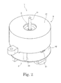
- Fig. 2 is a perspective view of a motor 1 according to the second preferred embodiment.
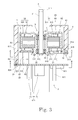
- Fig. 3 is a vertical cross-sectional view of the motor 1 according to the second preferred embodiment.
- the motor 1 is a brushless DC motor arranged to convert an alternating current supplied from an outside to a direct current and generate a torque with the resulting direct current.
- the motor 1 is used, for example, as a driving source of a household electrical appliance, such as a hair drier or a hand blender for cooking use.
- a household electrical appliance such as a hair drier or a hand blender for cooking use.
- motors according to preferred embodiments of the present invention may be installed in apparatuses other than household electrical appliances, such as automobiles, personal computers, and medical appliances.
- the motor 1 includes a stationary portion 2 and a rotating portion 3.
- the stationary portion 2 is fixed to a frame of an apparatus to be driven by the motor 1 through a support member 4.
- the rotating portion 3 is supported such that the rotating portion 3 is rotatable relative to the stationary portion 2.
- the support member 4 includes a cup portion 41 substantially in the shape of a covered cylinder, three first columnar portions 42, and three second columnar portions 43.
- Each of the first and second columnar portions 42 and 43 is arranged to extend downward from the cup portion 41 to assume the shape of a column.
- Each second columnar portion 43 is arranged to extend farther downward than each first columnar portion 42.
- the support member 4 may be either a portion of the motor 1 or a portion of the apparatus to be driven by the motor 1.
- the stationary portion 2 includes a mounting plate 21, a housing 22, a lower bearing portion 23, an upper bearing portion 24, a stator 25, and a circuit portion 26.
- the mounting plate 21 is a plate-shaped member made of a metal and fixed to the support member 4.
- the mounting plate 21 is arranged to extend substantially perpendicularly to a central axis 9.
- the mounting plate 21 is an exemplary attachment portion according to a preferred embodiment of the present invention.
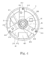
- Fig. 4 is a plan view of the motor 1 when viewed from a position indicated by line A-A shown in Fig. 3 .
- the mounting plate 21 according to the present preferred embodiment includes a central portion 211 and three arm portions 212.
- the central portion 211 is an annular portion arranged around the central axis 9.
- Each of the three arm portions 212 is arranged to extend radially outward from the central portion 211.
- Each arm portion 212 is fixed to a lower end portion of a separate one of the first columnar portions 42 in the vicinity of a radially outer end thereof.
- the arm portion 212 and the first columnar portion 42 may be fixed to each other through, for example, a screw. Note, however, that the arm portion 212 and the first columnar portion 42 may be fixed to each other through crimping or welding instead of the screw. In the present preferred embodiment illustrated in Fig. 3 , the arm portion 212 and the first columnar portion 42 are directly fixed to each other. Note, however, that another member may be arranged to intervene between the arm portion 212 and the first columnar portion 42.
- the housing 22 is a member made of a metal and supported by the mounting plate 21.
- the housing 22 according to the present preferred embodiment includes a bearing holding portion 221 and a crimping portion 222.
- the bearing holding portion 221 is arranged to extend in the axial direction around the central axis 9 to substantially assume the shape of a cylinder.
- the crimping portion 222 is arranged below the bearing holding portion 221.
- the crimping portion 222 is plastically deformed such that portions of the crimping portion 222 hold an inner circumferential edge of the central portion 211 of the mounting plate 21 from both sides in the vertical direction.
- the mounting plate 21 and the housing 22 are thereby fixed to each other.
- the mounting plate 21 and the housing 22 may be fixed to each other through screws or welding instead of crimping.
- another member may be arranged to intervene between the mounting plate 21 and the housing 22.
- Each of the lower bearing portion 23 and the upper bearing portion 24 is held on a radially inner side of the bearing holding portion 221.
- a ball bearing which is arranged to cause outer and inner races to rotate relative to each other through balls, is used as each of the lower bearing portion 23 and the upper bearing portion 24 according to the present preferred embodiment.
- the outer race of each of the lower and upper bearing portions 23 and 24 is fixed to an inner circumferential surface of the bearing holding portion 221.
- the inner race of each of the lower and upper bearing portions 23 and 24 is fixed to a shaft 31 included in the rotating portion 3.
- the shaft 31 is thereby supported such that the shaft 31 is rotatable with respect to the housing 22.
- a bearing of another type such as a plain bearing or a fluid bearing, may be used in place of the ball bearing.
- the stator 25 includes a stator core 51, an insulator 52, and a plurality of coils 53.
- the stator core 51 is arranged radially outside the housing 22 and radially inside a plurality of magnets 33, which will be described below.
- the stator core 51 is defined by laminated steel sheets, that is, electromagnetic steel sheets placed one upon another in the axial direction, for example.
- the stator core 51 includes an annular core back 511 and a plurality of teeth 512 arranged to project radially outward from the core back 511.
- An inner circumferential surface of the core back 511 is fixed to an outer circumferential surface of the bearing holding portion 221.
- the teeth 512 are arranged at substantially regular intervals in the circumferential direction.
- the insulator 52 is a member made of a resin and attached to the stator core 51. An upper surface, a lower surface, and both circumferential end surfaces of each of the teeth 512 are covered with the insulator 52.
- the coils 53 are arranged in the circumferential direction radially outside the housing 22 and radially inside the magnets 33.
- Each coil 53 is defined by a conducting wire wound around the insulator 52.
- the conducting wire is wound around each of the teeth 512, which serves as a magnetic core, with the insulator 52 intervening therebetween.
- the insulator 52 is arranged to intervene between the teeth 512 and the coils 53 to prevent an electrical short circuit between the teeth 512 and the coils 53.
- an insulating coating may be applied to a surface of each of the teeth 512 instead of using the insulator 52.
- the circuit portion 26 is a unit arranged to define an electrical circuit to supply a drive current to the coils 53.
- the circuit portion 26 includes a first circuit board 61, a second circuit board 62, and an electrical connection portion 63.
- Each of the first circuit board 61 and the second circuit board 62 is a plate-shaped rigid board.
- Each of the first and second circuit boards 61 and 62 is arranged to extend substantially perpendicularly to the central axis 9.
- the first circuit board 61 is arranged axially below the coils 53 and axially above the mounting plate 21. End portions of the conducting wires defining the coils 53 are electrically connected to the first circuit board 61 through, for example, soldering.
- the second circuit board 62 is arranged axially below the mounting plate 21.
- An AC to DC conversion portion 621 arranged to convert the alternating current supplied from the outside to the direct current is mounted on the second circuit board 62.
- the first circuit board 61 and the second circuit board 62 are connected to each other through the electrical connection portion 63.
- the electrical connection portion 63 according to the present preferred embodiment includes a pair of block-shaped connectors 631 and 632. Once the connectors 631 and 632 are joined to each other, terminals in the respective connectors 631 and 632 are brought into contact with each other. An electrical circuit on the first circuit board 61 and an electrical circuit on the second circuit board 62 are thereby electrically connected to each other.
- the electrical connection portion 63 may be a lead wire, and that the electrical connection portion 63 may include both a connector and a lead wire.
- circuit portion 26 The detailed structure of the circuit portion 26 will be described below.
- the rotating portion 3 includes the shaft 31, a rotor holder 32, and the plurality of magnets 33.
- the shaft 31 is a columnar member arranged along the central axis 9.
- a metal such as stainless steel, for example, is used as a material of the shaft 31.
- the shaft 31 is arranged to rotate about the central axis 9 while being supported by the lower bearing portion 23 and the upper bearing portion 24 described above.
- an upper end portion 311 of the shaft 31 is arranged axially above an upper surface of a top plate portion 321 of the rotor holder 32, which will be described below.
- a member, such as an impeller, which is to be driven by the motor 1 is attached to the upper end portion 311 of the shaft 31.
- the rotor holder 32 is a member made of a metal and fixed to the shaft 31.
- the rotor holder 32 is obtained, for example, by subjecting a galvanized steel sheet, which is a magnetic body, to press working.
- the rotor holder 32 includes the top plate portion 321 and a wall portion 322.
- the top plate portion 321 is arranged to extend substantially perpendicularly to the central axis 9 around the shaft 31.
- the shaft 31 is inserted into a circular hole defined in a center of the top plate portion 321.
- the wall portion 322 is arranged to extend axially downward from an outer end portion of the top plate portion 321 to substantially assume the shape of a cylinder.
- the plurality of magnets 33 are held on an inner circumferential surface of the wall portion 322.
- a radially inner surface of each magnet 33 is a pole surface to be opposed to a radially outer end surface of each of the teeth 512.
- the magnets 33 are arranged in the circumferential direction such that north and south poles are arranged alternately.
- Each of the magnets 33 may be directly fixed to the inner circumferential surface of the wall portion 322 as illustrated in Fig. 3 , or may alternatively be fixed to the inner circumferential surface of the wall portion 322 through a yoke made of a magnetic material. Note that, in place of the magnets 33, a single annular magnet in which north and south poles are arranged alternately in the circumferential direction may be used.
- an alternating current supplied from the AC power supply is converted in the AC to DC conversion portion 621 on the second circuit board 62 to a direct current.
- the resulting direct current flows through circuits mounted on the second circuit board 62 and the first circuit board 61, whereby the drive current is generated.
- the drive current is supplied to the coils 53, magnetic flux is generated around each of the teeth 512 of the stator core 51. Then, a circumferential torque is produced by interaction between the magnetic flux of the teeth 512 and that of the magnets 33, so that the rotating portion 3 is caused to rotate about the central axis 9.
- circuit portion 26 Next, the structure of the circuit portion 26 will be described in more detail below.
- the circuit portion 26 includes the first circuit board 61 and the second circuit board 62.
- the first circuit board 61 and the second circuit board 62 are arranged one above the other with the mounting plate 21 arranged therebetween.
- the two circuit boards 61 and 62 are arranged one above the other in the axial direction. This contributes to reducing the outside diameter of each of the first and second circuit boards 61 and 62 while securing a large area in which electronic components can be mounted. This in turn contributes to reducing the radial dimension of the motor 1.
- An upper surface of the first circuit board 61 includes land portions (not shown) where a copper foil is exposed.
- the conducting wires extending from the coils 53 are soldered to the land portions.
- a Hall element 611 which is a magnetic sensor, is mounted on the upper surface of the first circuit board 61.
- the Hall element 611 is arranged to detect the magnetic flux of the magnets 33 to detect a rotational position of the rotating portion 3 while the motor 1 is running.
- the Hall element 611 is arranged on the upper surface of the first circuit board 61, which is closer to the magnets 33 than is the second circuit board 62. This increases precision with which the rotational position of the rotating portion 3 is detected.
- the AC to DC conversion portion 621, a transistor array 622, and a control IC 623 are mounted on a lower surface of the second circuit board 62.
- the AC to DC conversion portion 621 includes an electrolytic capacitor 71, a rectifier 72, and an inductor 73.
- Each of these electronic components is greater in volume than any electronic component mounted on the first circuit board 61.
- such electronic components having large volumes are mounted on the lower surface of the second circuit board 62. This makes it possible to arrange the first circuit board 61 and the second circuit board 62 closer to each other. This in turn enables more effective use of a space around the circuit portion 26.
- the first circuit board 61 includes a body portion 612 which is substantially circular in a plan view, and a projecting portion 613 arranged to project radially outward from the body portion 612.
- the body portion 612 is a portion of the first circuit board 61 which is surrounded by a broken line.
- At least a portion of the connector 631 is arranged on the projecting portion 613. This reduces an area occupied by the connector 631 on the body portion 612. This in turn contributes to securing a larger space on the body portion 612 in which electronic components other than the connector 631 can be arranged.
- Each of the three arm portions 212 of the mounting plate 21 is arranged to extend radially outward beyond an outer circumference of the body portion 612 of the first circuit board 61.
- Each arm portion 212 is fixed to a corresponding one of the first columnar portions 42 of the support member 4 at a position radially outward of the body portion 612.
- each of the three arm portions 212 includes a first fixing portion 213 fixed to the corresponding first columnar portion 42 at a position radially outward of the body portion 612 of the first circuit board 61.
- each arm portion 212 includes a board fixing portion 214 at a position radially inward of the first fixing portion 213.
- a portion of the arm portion 212 is caused to rise in a cylindrical shape by so-called fluing, and an upper end portion thereof is caused to collapse to make contact with the upper surface of the first circuit board 61, whereby the board fixing portion 214 is defined.
- the first circuit board 61 is fixed to the mounting plate 21 through the board fixing portions 214.
- another fixing method such as screwing, may be employed to fix the mounting plate 21 and the first circuit board 61 to each other.
- each arm portion 212 includes a board contact surface 215 arranged to be in contact with a lower surface of the first circuit board 61.
- the board fixing portion 214 includes at least a portion of the board contact surface 215.
- the board contact surface 215 is arranged at a level higher than that of an upper surface of the central portion 211.
- the first circuit board 61 is axially positioned by contact with the board contact surfaces 215.
- the contact between the mounting plate 21 and the first circuit board 61 contributes to reducing the axial dimension of a combination of the mounting plate 21 and the first circuit board 61. This in turn contributes to reducing the axial dimension of the motor 1.
- the contact between the first circuit board 61 and the mounting plate 21 contributes to reducing vibrations of the first circuit board 61.
- the board contact surfaces 215 are arranged not in the central portion 211 of the mounting plate 21 but in upper surfaces of the arm portions 212. Therefore, the first circuit board 61 is arranged to be in contact with each board contact surface 215 of the mounting plate 21 in the vicinity of a radially outer edge thereof. This contributes to more effectively reducing the vibrations of the first circuit board 61.
- a substantially circular through hole 610 is defined in a center of the body portion 612 of the first circuit board 61.
- the housing 22 is arranged to extend in the vertical direction through the through hole 610. Insertion of the housing 22 through the through hole 610 of the first circuit board 61 as described above makes it possible to arrange the first circuit board 61 at a level higher than that of a lower end portion of the housing 22, that is, makes it possible to arrange the first circuit board 61 closer to the magnets 33. This contributes to reducing the axial dimension of a combination of the first circuit board 61 and the housing 22. This in turn contributes to further reducing the axial dimension of the motor 1.
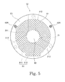
- Fig. 5 is a plan view of the motor 1 when viewed from a position indicated by line B-B shown in Fig. 3 . Note, however, that the electronic components mounted on the second circuit board 62 are not shown in Fig. 5 .
- the second circuit board 62 is arranged to be substantially circular in the plan view.
- the second circuit board 62 is arranged to have an outside diameter greater than the outside diameter of the body portion 612 of the first circuit board 61.
- the second circuit board 62 includes a first region 81, a second region 82, and a third region 83.
- the first region 81 is a region of the second circuit board 62 which axially coincides with the first circuit board 61. In Fig. 5 , the first region 81 is indicated by cross-hatching.
- the second region 82 is a region of the second circuit board 62 which axially coincides with the through hole 610 of the first circuit board 61.
- the third region 83 is a region of the second circuit board 62 which axially overlaps with neither the first circuit board 61 nor the through hole 610.
- the second circuit board 62 is fixed to the second columnar portions 43 of the support member 4 at positions radially outward of the body portion 612 of the first circuit board 61.
- each second columnar portion 43 is fixed to the third region 83 of the second circuit board 62. That is, the second circuit board 62 includes, in the third region 83, second fixing portions 624 each of which is fixed to a corresponding one of the second columnar portions 43.
- a region which does not axially overlap with the first circuit board 61 is employed to fix the support member 4 and the second circuit board 62 to each other. This contributes to reducing the radial dimension of the circuit portion 26.
- the second circuit board 62 and each second columnar portion 43 may be fixed to each other through, for example, a screw. Note, however, that the second circuit board 62 and each second columnar portion 43 may be fixed to each other through crimping or welding instead of the screw. In the present preferred embodiment illustrated in Fig. 3 , the second circuit board 62 and each second columnar portion 43 are directly fixed to each other. Note, however, that another member may be arranged to intervene between the second circuit board 62 and each second columnar portion 43.
- the second circuit board 62 is fixed to the support member 4 at circumferential positions different from those of the arm portions 212 of the mounting plate 21. That is, the first fixing portions 213 of the mounting plate 21 and the second fixing portions 624 of the second circuit board 62 are arranged at different circumferential positions. This prevents the first fixing portions 213 and the second fixing portions 624 from limiting the radial positions of each other. This contributes to further reducing the radial dimension of the motor 1.
- Each arm portion 212 is fixed to the support member 4 at a position axially overlapping with the third region 83 of the second circuit board 62.
- the positions at which the mounting plate 21 is fixed to the support member 4 and the positions at which the second circuit board 62 are fixed to the support member 4 are arranged on the same circle in a plan view. This contributes to further reducing the radial dimension of the motor 1.
- the mounting plate 21 is arranged between the first circuit board 61 and the second circuit board 62.
- the mounting plate 21 and the housing 22 are fixed to each other between the first circuit board 61 and the second circuit board 62.
- Each of the lower end portion of the housing 22 and a lower end portion of the shaft 31 is arranged axially above an upper surface of the second circuit board 62. This eliminates a need to define, in the first region 81 and the second region 82 of the second circuit board 62, a through hole or a cut through which the housing 22 and the shaft 31 are arranged to pass. This contributes to increasing an area in which the electronic components can be mounted on the second circuit board 62. Moreover, a reduction in the axial dimension of the motor 1 is achieved compared to the case where the mounting plate 21 is arranged axially below the second circuit board 62.
- AC to DC conversion is performed on the second circuit board 62, which is the closer to the AC power supply of the two circuit boards 61 and 62.
- the motor 1 is a so-called outer-rotor motor, in which the magnets 33 are arranged radially outside the stator 25.
- the outer-rotor motor is able to easily achieve reductions in radial dimension and size and an increase in efficiency.
- the rotor holder 32 arranged to join the shaft 31 and the magnets 33 to each other is required, and therefore, the circuit portion 26 can be arranged only on one axial side of the magnets 33. That is, the outer-rotor motor has more severe restrictions on the arrangement of the circuit portion 26 than the inner-rotor motor.
- the motor 1 according to the present preferred embodiment is of an outer-rotor type, and is able to secure a large area on which the electronic components can be mounted in the circuit portion 26 while achieving a reduction in the radial dimension of the motor 1.
- Fig. 6 is a vertical cross-sectional view of a motor 1B according to an example modification of the second preferred embodiment.
- an insulator 52B includes an insulating portion 521B, a leg portion 522B, and a claw portion 523B.
- the insulating portion 521B is arranged to intervene between teeth 512B and coils 53B.
- the leg portion 522B is arranged to extend axially downward from the insulating portion 521B.
- a lower end portion of the leg portion 522B is arranged axially below the coils 53B.
- the claw portion 523B is arranged to project radially outward from the lower end portion of the leg portion 522B.
- An upper surface of the claw portion 523B is arranged to be in contact with a lower surface of a first circuit board 61B.
- the first circuit board 61B is supported not by a mounting plate 21B but by the claw portion 523B of the insulator 52B.
- the above arrangements eliminate a need to define, in the first circuit board 61B, a hole or a cut used to fix the first circuit board 61B to the mounting plate 21B. This contributes to increasing an area in which electronic components can be mounted on the first circuit board 61B.
- the support member 4 is arranged to be circular in a plan view.
- the shape of the support member 4 in the plan view may be arranged to be rectangular or the like.
- the shape of each of the first circuit board and the second circuit board may also be arranged to be rectangular or the like.
- the circuit portion may include another circuit board in addition to the first and second circuit boards.
- the through hole through which the housing is arranged to pass is defined in the center of the first circuit board.
- a cut through which the housing is arranged to pass may be defined in the first circuit board in place of the through hole.
- the third region of the second circuit board refers to a region of the second circuit board which axially overlaps with neither the first circuit board nor the cut.
- the cut may be in any shape as long as the cut is arranged to axially overlap with the housing.
- the shape of the first circuit board may become substantially fan-shaped or semicircular as a result of the cut being defined in the first circuit board.
- motors according to preferred embodiments of the present invention may differ in details of the structure from the motors according to the above-described preferred embodiments and the modifications thereof. Also note that features of the above-described preferred embodiments and the modifications thereof may be combined appropriately as long as no conflict arises.
- the present invention is applicable to motors.
Landscapes
- Engineering & Computer Science (AREA)
- Power Engineering (AREA)
- Microelectronics & Electronic Packaging (AREA)
- Motor Or Generator Frames (AREA)
- Brushless Motors (AREA)
Abstract
Description
- The present invention relates to a motor.
- Household electrical appliances, such as hair driers, are connected to household AC power supplies. Accordingly, AC motors have often been installed in the household electrical appliances. However, use of brushless DC motors in place of the AC motors makes it easier to provide high added value, such as fine rotation control. However, in order to drive the brushless DC motor by using the household AC power supply, an AC to DC converter arranged to convert an alternating current to a direct current is required. Accordingly, there is an increasing demand for brushless DC motors in which AC to DC converters are installed and which are designed for household electrical appliances.
- A known motor including a converter circuit is described, for example, in
JP-A 10-322973 - Motors installed in household electrical appliances are often arranged in portions to be grasped by users, or in channels for gases. Therefore, a reduction in the outside diameter of the motor leads directly to a reduction in the size of the household electrical appliance. However, it is difficult to reduce the outside diameter of the motor in the case where a large number of electronic components including an AC to DC converter are to be mounted on a circuit board of the motor to expand functionality of the household electrical appliance.
- The present invention has been conceived to provide, regarding a motor including a circuit board on which an AC to DC conversion portion is mounted, a structure which is able to achieve a reduction in the radial dimension of the motor while securing a large area in which electronic components can be mounted on the circuit board.
- A brushless DC motor according to a preferred embodiment of the present invention is arranged to convert an alternating current to a direct current and generate a torque with the resulting direct current, and includes a stationary portion fixed to a frame of an apparatus to be driven by the motor through a support member, and a rotating portion arranged to rotate about a central axis extending in a vertical direction relative to the stationary portion. The rotating portion includes a shaft arranged along the central axis; a rotor holder including a top plate portion arranged to extend around the shaft, and a cylindrical wall portion arranged to extend axially downward from an outer end portion of the top plate portion; and a magnet fixed to an inner circumferential surface of the wall portion directly or through a yoke. The stationary portion includes a bearing portion arranged to rotatably support the shaft; a housing including a cylindrical bearing holding portion arranged to hold the bearing portion; a plurality of coils arranged in a circumferential direction radially outside the housing and radially inside the magnet; an attachment portion fixed to each of the housing and the support member directly or through another member; and a circuit portion electrically connected to the coils. The circuit portion includes a plate-shaped first circuit board arranged axially below the coils and axially above the attachment portion, and to which end portions of conducting wires defining the coils are connected; a plate-shaped second circuit board arranged axially below the attachment portion, and arranged to have an AC to DC conversion portion mounted thereon; and an electrical connection portion arranged to electrically connect the first and second circuit boards to each other. The first circuit board includes a through hole or a cut defined therein. The housing is arranged to extend in the vertical direction through the through hole or the cut. The second circuit board includes a first region axially coinciding with the first circuit board; a second region axially coinciding with the through hole or the cut; and a third region axially overlapping with neither the first circuit board nor the through hole or the cut. The support member is fixed to the third region.
- According to the above preferred embodiment of the present invention, two circuit boards are arranged one above the other in an axial direction, and accordingly, a reduction in the radial dimension of the motor is achieved while a large area in which electronic components can be mounted is secured. In addition, the attachment portion is arranged between the first circuit board and the second circuit board. This leads to an increase in an area in which electronic components can be mounted on the second circuit board, and also leads to a reduction in the axial dimension of the motor.
-
-
Fig. 1 is a vertical cross-sectional view of a motor according to a first preferred embodiment of the present invention. -
Fig. 2 is a perspective view of a motor according to a second preferred embodiment of the present invention. -
Fig. 3 is a vertical cross-sectional view of the motor according to the second preferred embodiment. -
Fig. 4 is a plan view of the motor when viewed from a position indicated by line A-A shown inFig. 3 . -
Fig. 5 is a plan view of the motor when viewed from a position indicated by line B-B shown inFig. 3 . -
Fig. 6 is a vertical cross-sectional view of a motor according to an example modification of the second preferred embodiment. - Hereinafter, preferred embodiments of the present invention will be described with reference to the accompanying drawings. It is assumed herein that a direction parallel to a central axis of a motor is referred to by the term "axial direction", "axial", or "axially", that directions perpendicular to the central axis of the motor are referred to by the term "radial direction", "radial", or "radially", and that a direction along a circular arc centered on the central axis of the motor is referred to by the term "circumferential direction", "circumferential", or "circumferentially". It is also assumed herein that an axial direction is a vertical direction, and that a side on which coils are arranged with respect to a circuit portion is defined as an upper side. The shape of each member or portion and relative positions of different members or portions will be described based on the above assumptions. It should be noted, however, that the above definitions of the vertical direction and the upper and lower sides are not meant to restrict in any way the orientation of a motor according to any preferred embodiment of the present invention during manufacture and when in use.
- Also note that the wording "parallel direction" as used herein comprehends substantially parallel directions. Also note that the wording "perpendicular direction" as used herein comprehends substantially perpendicular directions.
-
Fig. 1 is a vertical cross-sectional view of a motor 1A according to a first preferred embodiment of the present invention. The motor 1A is a brushless DC motor arranged to convert an alternating current to a direct current and generate a torque with the resulting direct current. Referring toFig. 1 , the motor 1A includes astationary portion 2A and a rotatingportion 3A arranged to rotate about acentral axis 9A. Thestationary portion 2A is fixed to a frame of an apparatus to be driven by the motor 1A through asupport member 4A. The rotatingportion 3A is arranged to rotate relative to thestationary portion 2A. - The rotating
portion 3A includes ashaft 31A, arotor holder 32A, and amagnet 33A. Theshaft 31A is arranged along thecentral axis 9A. Therotor holder 32A includes atop plate portion 321A and awall portion 322A. Thetop plate portion 321A is arranged to extend substantially in the shape of a disk around theshaft 31A. Thewall portion 322A is substantially cylindrical, and is arranged to extend axially downward from an outer end portion of thetop plate portion 321A. Themagnet 33A is held on an inner circumferential surface of thewall portion 322A directly or through a yoke. - The
stationary portion 2A includes anattachment portion 21A, ahousing 22A, bearingportions coils 53A, and acircuit portion 26A. Theattachment portion 21A is fixed to each of thehousing 22A and thesupport member 4A directly or through another member. Thehousing 22A includes a substantially cylindricalbearing holding portion 221A. Each of the bearingportions bearing holding portion 221A, and is arranged to rotatably support theshaft 31A. Thecoils 53A are arranged in a circumferential direction radially outside thehousing 22A and radially inside themagnet 33A. Thecoils 53A are electrically connected to an electrical circuit mounted on thecircuit portion 26A. - The
circuit portion 26A includes a plate-shapedfirst circuit board 61A, a plate-shapedsecond circuit board 62A, and anelectrical connection portion 63A. Thefirst circuit board 61A is arranged axially below thecoils 53A and axially above theattachment portion 21A. End portions of conducting wires defining thecoils 53A are connected to thefirst circuit board 61A. Thehousing 22A is arranged to extend in the vertical direction through athrough hole 610A defined in thefirst circuit board 61A. Thesecond circuit board 62A is arranged axially below theattachment portion 21A. An AC toDC conversion portion 621A is mounted on thesecond circuit board 62A. Theelectrical connection portion 63A is arranged to electrically connect thefirst circuit board 61A and thesecond circuit board 62A to each other. - Referring to
Fig. 1 , thesecond circuit board 62A includes a first region 81A, asecond region 82A, and athird region 83A. The first region 81A is a region of thesecond circuit board 62A which axially coincides with thefirst circuit board 61A. Thesecond region 82A is a region of thesecond circuit board 62A which axially coincides with the throughhole 610A. Thethird region 83A is a region of thesecond circuit board 62A which axially overlaps with neither thefirst circuit board 61A nor the throughhole 610A. Thesecond circuit board 62A is fixed to thesupport member 4A at thethird region 83A. - In the motor 1A, the
first circuit board 61A and thesecond circuit board 62A are arranged one above the other in the axial direction. This contributes to reducing the radial dimension of the motor 1A while securing a large area in which electronic components can be mounted. In addition, theattachment portion 21A is arranged between thefirst circuit board 61A and thesecond circuit board 62A. This eliminates a need to define, in thesecond circuit board 62A, a hole or a cut through which thehousing 22A is arranged to pass. This contributes to increasing an area in which electronic components can be mounted on thesecond circuit board 62A. Moreover, a reduction in the axial dimension of the motor 1A is achieved compared to the case where theattachment portion 21A is arranged axially below thesecond circuit board 62A. - Next, a second preferred embodiment of the present invention will be described below.
Fig. 2 is a perspective view of amotor 1 according to the second preferred embodiment.Fig. 3 is a vertical cross-sectional view of themotor 1 according to the second preferred embodiment. Themotor 1 is a brushless DC motor arranged to convert an alternating current supplied from an outside to a direct current and generate a torque with the resulting direct current. Themotor 1 is used, for example, as a driving source of a household electrical appliance, such as a hair drier or a hand blender for cooking use. Note, however, that motors according to preferred embodiments of the present invention may be installed in apparatuses other than household electrical appliances, such as automobiles, personal computers, and medical appliances. - Referring to
Figs. 2 and3 , themotor 1 according to the present preferred embodiment includes astationary portion 2 and arotating portion 3. Thestationary portion 2 is fixed to a frame of an apparatus to be driven by themotor 1 through asupport member 4. The rotatingportion 3 is supported such that therotating portion 3 is rotatable relative to thestationary portion 2. Thesupport member 4 includes acup portion 41 substantially in the shape of a covered cylinder, three firstcolumnar portions 42, and three secondcolumnar portions 43. Each of the first and secondcolumnar portions cup portion 41 to assume the shape of a column. Each secondcolumnar portion 43 is arranged to extend farther downward than each firstcolumnar portion 42. Thesupport member 4 may be either a portion of themotor 1 or a portion of the apparatus to be driven by themotor 1. - The
stationary portion 2 according to the present preferred embodiment includes a mountingplate 21, ahousing 22, alower bearing portion 23, anupper bearing portion 24, astator 25, and acircuit portion 26. - The mounting
plate 21 is a plate-shaped member made of a metal and fixed to thesupport member 4. The mountingplate 21 is arranged to extend substantially perpendicularly to a central axis 9. The mountingplate 21 is an exemplary attachment portion according to a preferred embodiment of the present invention.Fig. 4 is a plan view of themotor 1 when viewed from a position indicated by line A-A shown inFig. 3 . Referring toFigs. 3 and4 , the mountingplate 21 according to the present preferred embodiment includes acentral portion 211 and threearm portions 212. Thecentral portion 211 is an annular portion arranged around the central axis 9. Each of the threearm portions 212 is arranged to extend radially outward from thecentral portion 211. - Each
arm portion 212 is fixed to a lower end portion of a separate one of the firstcolumnar portions 42 in the vicinity of a radially outer end thereof. Thearm portion 212 and the firstcolumnar portion 42 may be fixed to each other through, for example, a screw. Note, however, that thearm portion 212 and the firstcolumnar portion 42 may be fixed to each other through crimping or welding instead of the screw. In the present preferred embodiment illustrated inFig. 3 , thearm portion 212 and the firstcolumnar portion 42 are directly fixed to each other. Note, however, that another member may be arranged to intervene between thearm portion 212 and the firstcolumnar portion 42. - The
housing 22 is a member made of a metal and supported by the mountingplate 21. Thehousing 22 according to the present preferred embodiment includes abearing holding portion 221 and a crimpingportion 222. Thebearing holding portion 221 is arranged to extend in the axial direction around the central axis 9 to substantially assume the shape of a cylinder. The crimpingportion 222 is arranged below thebearing holding portion 221. During manufacture of themotor 1, the crimpingportion 222 is plastically deformed such that portions of the crimpingportion 222 hold an inner circumferential edge of thecentral portion 211 of the mountingplate 21 from both sides in the vertical direction. The mountingplate 21 and thehousing 22 are thereby fixed to each other. Note that the mountingplate 21 and thehousing 22 may be fixed to each other through screws or welding instead of crimping. Also note that another member may be arranged to intervene between the mountingplate 21 and thehousing 22. - Each of the
lower bearing portion 23 and theupper bearing portion 24 is held on a radially inner side of thebearing holding portion 221. A ball bearing, which is arranged to cause outer and inner races to rotate relative to each other through balls, is used as each of thelower bearing portion 23 and theupper bearing portion 24 according to the present preferred embodiment. The outer race of each of the lower andupper bearing portions bearing holding portion 221. The inner race of each of the lower andupper bearing portions shaft 31 included in therotating portion 3. Theshaft 31 is thereby supported such that theshaft 31 is rotatable with respect to thehousing 22. Note, however, that a bearing of another type, such as a plain bearing or a fluid bearing, may be used in place of the ball bearing. - The
stator 25 includes astator core 51, aninsulator 52, and a plurality ofcoils 53. Thestator core 51 is arranged radially outside thehousing 22 and radially inside a plurality ofmagnets 33, which will be described below. Thestator core 51 is defined by laminated steel sheets, that is, electromagnetic steel sheets placed one upon another in the axial direction, for example. Thestator core 51 includes an annular core back 511 and a plurality ofteeth 512 arranged to project radially outward from the core back 511. An inner circumferential surface of the core back 511 is fixed to an outer circumferential surface of thebearing holding portion 221. Theteeth 512 are arranged at substantially regular intervals in the circumferential direction. - The
insulator 52 is a member made of a resin and attached to thestator core 51. An upper surface, a lower surface, and both circumferential end surfaces of each of theteeth 512 are covered with theinsulator 52. Thecoils 53 are arranged in the circumferential direction radially outside thehousing 22 and radially inside themagnets 33. Eachcoil 53 is defined by a conducting wire wound around theinsulator 52. In other words, according to the present preferred embodiment, the conducting wire is wound around each of theteeth 512, which serves as a magnetic core, with theinsulator 52 intervening therebetween. Theinsulator 52 is arranged to intervene between theteeth 512 and thecoils 53 to prevent an electrical short circuit between theteeth 512 and thecoils 53. - Note that an insulating coating may be applied to a surface of each of the
teeth 512 instead of using theinsulator 52. - The
circuit portion 26 is a unit arranged to define an electrical circuit to supply a drive current to thecoils 53. Thecircuit portion 26 includes afirst circuit board 61, asecond circuit board 62, and anelectrical connection portion 63. Each of thefirst circuit board 61 and thesecond circuit board 62 is a plate-shaped rigid board. Each of the first andsecond circuit boards first circuit board 61 is arranged axially below thecoils 53 and axially above the mountingplate 21. End portions of the conducting wires defining thecoils 53 are electrically connected to thefirst circuit board 61 through, for example, soldering. Thesecond circuit board 62 is arranged axially below the mountingplate 21. An AC toDC conversion portion 621 arranged to convert the alternating current supplied from the outside to the direct current is mounted on thesecond circuit board 62. - The
first circuit board 61 and thesecond circuit board 62 are connected to each other through theelectrical connection portion 63. Theelectrical connection portion 63 according to the present preferred embodiment includes a pair of block-shapedconnectors connectors respective connectors first circuit board 61 and an electrical circuit on thesecond circuit board 62 are thereby electrically connected to each other. Note, however, that theelectrical connection portion 63 may be a lead wire, and that theelectrical connection portion 63 may include both a connector and a lead wire. - The detailed structure of the
circuit portion 26 will be described below. - The rotating
portion 3 includes theshaft 31, arotor holder 32, and the plurality ofmagnets 33. - The
shaft 31 is a columnar member arranged along the central axis 9. A metal, such as stainless steel, for example, is used as a material of theshaft 31. Theshaft 31 is arranged to rotate about the central axis 9 while being supported by thelower bearing portion 23 and theupper bearing portion 24 described above. In addition, anupper end portion 311 of theshaft 31 is arranged axially above an upper surface of atop plate portion 321 of therotor holder 32, which will be described below. A member, such as an impeller, which is to be driven by themotor 1 is attached to theupper end portion 311 of theshaft 31. - The
rotor holder 32 is a member made of a metal and fixed to theshaft 31. Therotor holder 32 is obtained, for example, by subjecting a galvanized steel sheet, which is a magnetic body, to press working. Therotor holder 32 includes thetop plate portion 321 and awall portion 322. Thetop plate portion 321 is arranged to extend substantially perpendicularly to the central axis 9 around theshaft 31. Theshaft 31 is inserted into a circular hole defined in a center of thetop plate portion 321. Thewall portion 322 is arranged to extend axially downward from an outer end portion of thetop plate portion 321 to substantially assume the shape of a cylinder. - The plurality of
magnets 33 are held on an inner circumferential surface of thewall portion 322. A radially inner surface of eachmagnet 33 is a pole surface to be opposed to a radially outer end surface of each of theteeth 512. Themagnets 33 are arranged in the circumferential direction such that north and south poles are arranged alternately. Each of themagnets 33 may be directly fixed to the inner circumferential surface of thewall portion 322 as illustrated inFig. 3 , or may alternatively be fixed to the inner circumferential surface of thewall portion 322 through a yoke made of a magnetic material. Note that, in place of themagnets 33, a single annular magnet in which north and south poles are arranged alternately in the circumferential direction may be used. - Once the
circuit portion 26 is connected to an external AC power supply, an alternating current supplied from the AC power supply is converted in the AC toDC conversion portion 621 on thesecond circuit board 62 to a direct current. Then, the resulting direct current flows through circuits mounted on thesecond circuit board 62 and thefirst circuit board 61, whereby the drive current is generated. Once the drive current is supplied to thecoils 53, magnetic flux is generated around each of theteeth 512 of thestator core 51. Then, a circumferential torque is produced by interaction between the magnetic flux of theteeth 512 and that of themagnets 33, so that therotating portion 3 is caused to rotate about the central axis 9. - Next, the structure of the
circuit portion 26 will be described in more detail below. - As described above, the
circuit portion 26 includes thefirst circuit board 61 and thesecond circuit board 62. Thefirst circuit board 61 and thesecond circuit board 62 are arranged one above the other with the mountingplate 21 arranged therebetween. Thus, in themotor 1, the twocircuit boards second circuit boards motor 1. - An upper surface of the
first circuit board 61 includes land portions (not shown) where a copper foil is exposed. The conducting wires extending from thecoils 53 are soldered to the land portions. In addition, aHall element 611, which is a magnetic sensor, is mounted on the upper surface of thefirst circuit board 61. TheHall element 611 is arranged to detect the magnetic flux of themagnets 33 to detect a rotational position of therotating portion 3 while themotor 1 is running. According to the present preferred embodiment, theHall element 611 is arranged on the upper surface of thefirst circuit board 61, which is closer to themagnets 33 than is thesecond circuit board 62. This increases precision with which the rotational position of therotating portion 3 is detected. - The AC to
DC conversion portion 621, atransistor array 622, and acontrol IC 623 are mounted on a lower surface of thesecond circuit board 62. The AC toDC conversion portion 621 includes anelectrolytic capacitor 71, arectifier 72, and aninductor 73. Each of these electronic components is greater in volume than any electronic component mounted on thefirst circuit board 61. According to the present preferred embodiment, such electronic components having large volumes are mounted on the lower surface of thesecond circuit board 62. This makes it possible to arrange thefirst circuit board 61 and thesecond circuit board 62 closer to each other. This in turn enables more effective use of a space around thecircuit portion 26. - Referring to
Fig. 4 , thefirst circuit board 61 includes abody portion 612 which is substantially circular in a plan view, and a projectingportion 613 arranged to project radially outward from thebody portion 612. InFig. 4 , thebody portion 612 is a portion of thefirst circuit board 61 which is surrounded by a broken line. At least a portion of theconnector 631 is arranged on the projectingportion 613. This reduces an area occupied by theconnector 631 on thebody portion 612. This in turn contributes to securing a larger space on thebody portion 612 in which electronic components other than theconnector 631 can be arranged. - Each of the three
arm portions 212 of the mountingplate 21 is arranged to extend radially outward beyond an outer circumference of thebody portion 612 of thefirst circuit board 61. Eacharm portion 212 is fixed to a corresponding one of the firstcolumnar portions 42 of thesupport member 4 at a position radially outward of thebody portion 612. In other words, each of the threearm portions 212 includes afirst fixing portion 213 fixed to the corresponding firstcolumnar portion 42 at a position radially outward of thebody portion 612 of thefirst circuit board 61. - In addition, each
arm portion 212 includes aboard fixing portion 214 at a position radially inward of thefirst fixing portion 213. During the manufacture of themotor 1, a portion of thearm portion 212 is caused to rise in a cylindrical shape by so-called fluing, and an upper end portion thereof is caused to collapse to make contact with the upper surface of thefirst circuit board 61, whereby theboard fixing portion 214 is defined. Thefirst circuit board 61 is fixed to the mountingplate 21 through theboard fixing portions 214. Note, however, that another fixing method, such as screwing, may be employed to fix the mountingplate 21 and thefirst circuit board 61 to each other. - In addition, each
arm portion 212 includes aboard contact surface 215 arranged to be in contact with a lower surface of thefirst circuit board 61. Theboard fixing portion 214 includes at least a portion of theboard contact surface 215. Theboard contact surface 215 is arranged at a level higher than that of an upper surface of thecentral portion 211. Thefirst circuit board 61 is axially positioned by contact with the board contact surfaces 215. Moreover, the contact between the mountingplate 21 and thefirst circuit board 61 contributes to reducing the axial dimension of a combination of the mountingplate 21 and thefirst circuit board 61. This in turn contributes to reducing the axial dimension of themotor 1. - Furthermore, the contact between the
first circuit board 61 and the mountingplate 21 contributes to reducing vibrations of thefirst circuit board 61. In particular, according to the present preferred embodiment, the board contact surfaces 215 are arranged not in thecentral portion 211 of the mountingplate 21 but in upper surfaces of thearm portions 212. Therefore, thefirst circuit board 61 is arranged to be in contact with eachboard contact surface 215 of the mountingplate 21 in the vicinity of a radially outer edge thereof. This contributes to more effectively reducing the vibrations of thefirst circuit board 61. - Referring to
Figs. 3 and4 , a substantially circular throughhole 610 is defined in a center of thebody portion 612 of thefirst circuit board 61. Thehousing 22 is arranged to extend in the vertical direction through the throughhole 610. Insertion of thehousing 22 through the throughhole 610 of thefirst circuit board 61 as described above makes it possible to arrange thefirst circuit board 61 at a level higher than that of a lower end portion of thehousing 22, that is, makes it possible to arrange thefirst circuit board 61 closer to themagnets 33. This contributes to reducing the axial dimension of a combination of thefirst circuit board 61 and thehousing 22. This in turn contributes to further reducing the axial dimension of themotor 1. -
Fig. 5 is a plan view of themotor 1 when viewed from a position indicated by line B-B shown inFig. 3 . Note, however, that the electronic components mounted on thesecond circuit board 62 are not shown inFig. 5 . Referring toFig. 5 , thesecond circuit board 62 is arranged to be substantially circular in the plan view. Thesecond circuit board 62 is arranged to have an outside diameter greater than the outside diameter of thebody portion 612 of thefirst circuit board 61. - The
second circuit board 62 includes afirst region 81, asecond region 82, and athird region 83. Thefirst region 81 is a region of thesecond circuit board 62 which axially coincides with thefirst circuit board 61. InFig. 5 , thefirst region 81 is indicated by cross-hatching. Thesecond region 82 is a region of thesecond circuit board 62 which axially coincides with the throughhole 610 of thefirst circuit board 61. Thethird region 83 is a region of thesecond circuit board 62 which axially overlaps with neither thefirst circuit board 61 nor the throughhole 610. - The
second circuit board 62 is fixed to the secondcolumnar portions 43 of thesupport member 4 at positions radially outward of thebody portion 612 of thefirst circuit board 61. In particular, according to the present preferred embodiment, eachsecond columnar portion 43 is fixed to thethird region 83 of thesecond circuit board 62. That is, thesecond circuit board 62 includes, in thethird region 83, second fixingportions 624 each of which is fixed to a corresponding one of the secondcolumnar portions 43. Thus, in themotor 1, a region which does not axially overlap with thefirst circuit board 61 is employed to fix thesupport member 4 and thesecond circuit board 62 to each other. This contributes to reducing the radial dimension of thecircuit portion 26. - The
second circuit board 62 and eachsecond columnar portion 43 may be fixed to each other through, for example, a screw. Note, however, that thesecond circuit board 62 and eachsecond columnar portion 43 may be fixed to each other through crimping or welding instead of the screw. In the present preferred embodiment illustrated inFig. 3 , thesecond circuit board 62 and eachsecond columnar portion 43 are directly fixed to each other. Note, however, that another member may be arranged to intervene between thesecond circuit board 62 and eachsecond columnar portion 43. - In addition, the
second circuit board 62 is fixed to thesupport member 4 at circumferential positions different from those of thearm portions 212 of the mountingplate 21. That is, the first fixingportions 213 of the mountingplate 21 and thesecond fixing portions 624 of thesecond circuit board 62 are arranged at different circumferential positions. This prevents the first fixingportions 213 and thesecond fixing portions 624 from limiting the radial positions of each other. This contributes to further reducing the radial dimension of themotor 1. - Each
arm portion 212 is fixed to thesupport member 4 at a position axially overlapping with thethird region 83 of thesecond circuit board 62. In addition, referring toFig. 3 , the positions at which the mountingplate 21 is fixed to thesupport member 4 and the positions at which thesecond circuit board 62 are fixed to thesupport member 4 are arranged on the same circle in a plan view. This contributes to further reducing the radial dimension of themotor 1. - Moreover, in the
motor 1, the mountingplate 21 is arranged between thefirst circuit board 61 and thesecond circuit board 62. In addition, the mountingplate 21 and thehousing 22 are fixed to each other between thefirst circuit board 61 and thesecond circuit board 62. Each of the lower end portion of thehousing 22 and a lower end portion of theshaft 31 is arranged axially above an upper surface of thesecond circuit board 62. This eliminates a need to define, in thefirst region 81 and thesecond region 82 of thesecond circuit board 62, a through hole or a cut through which thehousing 22 and theshaft 31 are arranged to pass. This contributes to increasing an area in which the electronic components can be mounted on thesecond circuit board 62. Moreover, a reduction in the axial dimension of themotor 1 is achieved compared to the case where the mountingplate 21 is arranged axially below thesecond circuit board 62. - Moreover, according to the present preferred embodiment, AC to DC conversion is performed on the
second circuit board 62, which is the closer to the AC power supply of the twocircuit boards first circuit board 61. This leads to an additional reduction in a production cost of themotor 1. - Furthermore, the
motor 1 is a so-called outer-rotor motor, in which themagnets 33 are arranged radially outside thestator 25. When compared to an inner-rotor motor, the outer-rotor motor is able to easily achieve reductions in radial dimension and size and an increase in efficiency. However, in the case of the outer-rotor motor, therotor holder 32 arranged to join theshaft 31 and themagnets 33 to each other is required, and therefore, thecircuit portion 26 can be arranged only on one axial side of themagnets 33. That is, the outer-rotor motor has more severe restrictions on the arrangement of thecircuit portion 26 than the inner-rotor motor. Themotor 1 according to the present preferred embodiment is of an outer-rotor type, and is able to secure a large area on which the electronic components can be mounted in thecircuit portion 26 while achieving a reduction in the radial dimension of themotor 1. - While preferred embodiments of the present invention have been described above, it will be understood that the present invention is not limited to the above-described preferred embodiments.
-
Fig. 6 is a vertical cross-sectional view of a motor 1B according to an example modification of the second preferred embodiment. According to the modification illustrated inFig. 6 , aninsulator 52B includes an insulatingportion 521B, aleg portion 522B, and aclaw portion 523B. The insulatingportion 521B is arranged to intervene betweenteeth 512B and coils 53B. Theleg portion 522B is arranged to extend axially downward from the insulatingportion 521B. A lower end portion of theleg portion 522B is arranged axially below thecoils 53B. Theclaw portion 523B is arranged to project radially outward from the lower end portion of theleg portion 522B. An upper surface of theclaw portion 523B is arranged to be in contact with a lower surface of afirst circuit board 61B. As described above, according to the modification illustrated inFig. 6 , thefirst circuit board 61B is supported not by a mountingplate 21B but by theclaw portion 523B of theinsulator 52B. - The above arrangements eliminate a need to define, in the
first circuit board 61B, a hole or a cut used to fix thefirst circuit board 61B to the mountingplate 21B. This contributes to increasing an area in which electronic components can be mounted on thefirst circuit board 61B. - According to the second preferred embodiment described above, the
support member 4 is arranged to be circular in a plan view. Note, however, that the shape of thesupport member 4 in the plan view may be arranged to be rectangular or the like. Also note that the shape of each of the first circuit board and the second circuit board may also be arranged to be rectangular or the like. Also note that the circuit portion may include another circuit board in addition to the first and second circuit boards. - In each of the above-described first and second preferred embodiments, the through hole through which the housing is arranged to pass is defined in the center of the first circuit board. Note, however, that a cut through which the housing is arranged to pass may be defined in the first circuit board in place of the through hole. In this case, the third region of the second circuit board refers to a region of the second circuit board which axially overlaps with neither the first circuit board nor the cut. The cut may be in any shape as long as the cut is arranged to axially overlap with the housing. The shape of the first circuit board may become substantially fan-shaped or semicircular as a result of the cut being defined in the first circuit board.
- Note that motors according to preferred embodiments of the present invention may differ in details of the structure from the motors according to the above-described preferred embodiments and the modifications thereof. Also note that features of the above-described preferred embodiments and the modifications thereof may be combined appropriately as long as no conflict arises.
- The present invention is applicable to motors.
-
- 1, 1A, 1B
- motor
- 2, 2A
- stationary portion
- 3, 3A
- rotating portion
- 4, 4A
- support member
- 9, 9A
- central axis
- 21, 21B
- mounting plate
- 21A
- attachment portion
- 22, 22A
- housing
- 23, 23A, 24, 24A
- bearing portion
- 25
- stator
- 26, 26A
- circuit portion
- 31, 31A
- shaft
- 32, 32A
- rotor holder
- 33, 33A
- magnet
- 41
- cup portion
- 42
- first columnar portion
- 43
- second columnar portion
- 51, 51B
- stator core
- 52, 52B
- insulator
- 53, 53A, 53B
- coil
- 61, 61A, 61B
- first circuit board
- 62, 62A
- second circuit board
- 63, 63A
- electrical connection portion
- 71
- electrolytic capacitor
- 72
- rectifier
- 73
- inductor
- 81, 81A
- first region
- 82, 82A
- second region
- 83, 83A
- third region
- 211
- central portion
- 212
- arm portion
- 213
- first fixing portion
- 214
- board fixing portion
- 215
- board contact surface
- 221, 221A
- bearing holding portion
- 222
- crimping portion
- 321, 321A
- top plate portion
- 322, 322A
- wall portion
- 521B
- insulating portion
- 522B
- leg portion
- 523B
- claw portion
- 610, 610A
- through hole
- 611
- Hall element
- 612
- body portion
- 613
- projecting portion
- 621, 621A
- AC to DC conversion portion
- 622
- transistor array
- 623
- control IC
- 624
- second fixing portion
- 631, 632
- connector
Claims (15)
- A brushless DC motor (1, 1A, 1B) arranged to convert an alternating current to a direct current and generate a torque with the resulting direct current, the motor (1, 1A, 1B) comprising:a stationary portion (2, 2A) fixed to a frame of an apparatus to be driven by the motor through a support member (4, 4A); anda rotating portion (3, 3A) arranged to rotate about a central axis (9, 9A) extending in a vertical direction relative to the stationary portion (2, 2A); whereinthe rotating portion (3, 3A) includes:a shaft (31, 31A) arranged along the central axis (9, 9A);a rotor holder (32, 32A) including a top plate portion (321, 321A) arranged to extend around the shaft (31, 31A), and a cylindrical wall portion (322, 322A) arranged to extend axially downward from an outer end portion of the top plate portion (321, 321A); anda magnet (33, 33A) fixed to an inner circumferential surface of the wall portion (322, 322A) directly or through a yoke;the stationary portion (2, 2A) includes:a bearing portion (23, 23A, 24, 24A) arranged to rotatably support the shaft (31, 31A);a housing (22, 22A) including a cylindrical bearing holding portion (221, 221A) arranged to hold the bearing portion (23, 23A, 24, 24A);a plurality of coils (53, 53A, 53B) arranged in a circumferential direction radially outside the housing (22, 22A) and radially inside the magnet (33, 33A);an attachment portion (21A) fixed to each of the housing (22, 22A) and the support member (4, 4A) directly or through another member; anda circuit portion (26, 26A) electrically connected to the coils (53, 53A, 53B);the circuit portion (26, 26A) includes:a plate-shaped first circuit board (61, 61A, 61B) arranged axially below the coils (53, 53A, 53B) and axially above the attachment portion (21A), and to which end portions of conducting wires defining the coils (53, 53A, 53B) are connected;a plate-shaped second circuit board (62, 62A) arranged axially below the attachment portion (21A), and arranged to have an AC to DC conversion portion (621, 621A) mounted thereon; andan electrical connection portion (63, 63A) arranged to electrically connect the first and second circuit boards (61, 61A, 61B, 62, 62A) to each other;the first circuit board (61, 61A, 61B) includes a through hole (610, 610A) or a cut defined therein;the housing (22, 22A) is arranged to extend in the vertical direction through the through hole (610, 610A) or the cut;the second circuit board (62, 62A) includes:a first region (81, 81A) axially coinciding with the first circuit board (61, 61A, 61B);a second region (82, 82A) axially coinciding with the through hole (610, 610A) or the cut; anda third region (83, 83A) axially overlapping with neither the first circuit board (61, 61A, 61B) nor the through hole (610, 610A) or the cut; andthe support member (4, 4A) is fixed to the third region (83, 83A).
- The motor (1, 1A, 1B) according to claim 1, further comprising a sensor (611) arranged to detect a rotational position of the rotating portion (3, 3A), and mounted on an upper surface of the first circuit board (61, 61A, 61B).
- The motor (1, 1A, 1B) according to one of claims 1 and 2, wherein the AC to DC conversion portion (621, 621A) is mounted on a lower surface of the second circuit board (62, 62A).
- The motor (1, 1A, 1B) according to claim 3, wherein the AC to DC conversion portion (621, 621A) includes an electrolytic capacitor.
- The motor (1, 1A, 1B) according to any one of claims 1 to 4, further comprising at least one of a transistor array (622) mounted on a lower surface of the second circuit board (621, 621A) and a control IC (623) mounted on a lower surface of the second circuit board (62, 62A).
- The motor (1, 1A, 1B) according to any one of claims 1 to 5, wherein
the first circuit board (61, 61A, 61B) includes a body portion (612) arranged to be substantially circular in a plan view;
the second circuit board (62, 62A) is arranged to be substantially circular in a plan view; and
the body portion (612) is arranged to have an outside diameter smaller than an outside diameter of the second circuit board (62, 62A). - The motor (1, 1A, 1B) according to claim 6, wherein the support member (4, 4A) is fixed to the second circuit board (62, 62A) at a position radially outward of the body portion (612).
- The motor (1, 1A, 1B) according to any one of claims 1 to 7, comprising at least one of:the electrical connection portion (63, 63A) including at least one of a connector (631, 632) or a lead wire;the attachment portion (21A) being a plate-shaped member arranged to extend substantially perpendicularly to the central axis (9, 9A);the attachment portion (21A) being directly fixed to the support member (4, 4A); andan upper end portion of the shaft (31, 31A) being arranged axially above an upper surface of the top plate portion (321, 321A).
- The motor (1, 1A, 1B) according to any one of claims 1 to 8, wherein
the attachment portion (21A) includes:a central portion (211) fixed to the housing (22, 22A); anda plurality of arm portions (212) each of which is arranged to extend radially outward from the central portion (211); andeach arm portion (212) is fixed to the support member (4, 4A). - The motor (1, 1A, 1B) according to claim 9, wherein the second circuit board (62, 62A) is fixed to the support member (4, 4A) at a circumferential position different from a circumferential position of each arm portion (212).
- The motor (1, 1A, 1B) according to one of claims 9 and 10, wherein each arm portion (212) is fixed to the support member (4, 4A) at a position axially overlapping with the third region (83, 83A) of the second circuit board (62, 62A).
- The motor (1, 1A, 1B) according to any one of claims 9 to 11, wherein
each arm portion (212) includes a board contact surface (215) arranged at a level higher than that of an upper surface of the central portion (211); and
a lower surface of the first circuit board (61, 61A, 61B) is arranged to be in contact with the board contact surface (215). - The motor (1, 1A, 1B) according to claim 12, wherein
each arm portion (212) includes a board fixing portion (214) including at least a portion of the board contact surface (215); and
the first circuit board (61, 61A, 61B) is fixed to the board fixing portion (214). - The motor according to one of claims 1 and 2, wherein
a lower end portion of the housing (22, 22A) is arranged axially above an upper surface of the second circuit board (62, 62A); and
neither the first region (81, 81A) nor the second region (82, 82A) of the second circuit board (62, 62A) includes a through hole or a cut used to arrange any other member therein. - The motor according to any one of claims 1 to 14, wherein
the stationary portion (2, 2A) further includes:a stator core (51, 51B) arranged radially outside the housing (22, 22A) and radially inside the magnet (33, 33A); andan insulator (52, 52B) made of a resin and attached to the stator core (51, 51B);the insulator (52, 52B) includes:an insulating portion (521B) arranged to intervene between the stator core (51, 51B) and the coils (53, 53A, 53B);a leg portion (522B) arranged to extend axially downward from the insulating portion (521B), with a lower end portion of the leg portion (522B) being arranged axially below the coils (53, 53A, 53B); anda claw portion (523B) arranged to project radially outward from the lower end portion of the leg portion (522B); anda lower surface of the first circuit board (61, 61A, 61B) is arranged to be in contact with an upper surface of the claw portion (523B).
Applications Claiming Priority (1)
| Application Number | Priority Date | Filing Date | Title |
|---|---|---|---|
| JP2013232781A JP6281250B2 (en) | 2013-11-11 | 2013-11-11 | motor |
Publications (3)
| Publication Number | Publication Date |
|---|---|
| EP2874285A2 true EP2874285A2 (en) | 2015-05-20 |
| EP2874285A3 EP2874285A3 (en) | 2015-12-30 |
| EP2874285B1 EP2874285B1 (en) | 2018-04-11 |
Family
ID=51900130
Family Applications (1)
| Application Number | Title | Priority Date | Filing Date |
|---|---|---|---|
| EP14191611.4A Not-in-force EP2874285B1 (en) | 2013-11-11 | 2014-11-04 | Motor |
Country Status (4)
| Country | Link |
|---|---|
| US (1) | US9531243B2 (en) |
| EP (1) | EP2874285B1 (en) |
| JP (1) | JP6281250B2 (en) |
| CN (3) | CN204205844U (en) |
Cited By (1)
| Publication number | Priority date | Publication date | Assignee | Title |
|---|---|---|---|---|
| US20160206073A1 (en) * | 2015-01-16 | 2016-07-21 | Elchim S.P.A. | Electric hairdryer with a motor protecting device |
Families Citing this family (14)
| Publication number | Priority date | Publication date | Assignee | Title |
|---|---|---|---|---|
| JP6281250B2 (en) * | 2013-11-11 | 2018-02-21 | 日本電産株式会社 | motor |
| JP2016082669A (en) * | 2014-10-15 | 2016-05-16 | 日本電産株式会社 | Motor for ceiling fan, and ceiling fan |
| US9831580B2 (en) * | 2015-09-15 | 2017-11-28 | Ghsp, Inc. | Vehicle-mounted sensorless motor with edge-connected termination |
| EP3514923B1 (en) * | 2016-10-27 | 2020-07-29 | SZ DJI Osmo Technology Co., Ltd. | Motor, cradle head and photographing device |
| JP2018093575A (en) * | 2016-11-30 | 2018-06-14 | 日本電産株式会社 | Stator unit and motor |
| CN108233584A (en) * | 2016-12-22 | 2018-06-29 | 日本电产(东莞)有限公司 | Motor |
| JP2018201302A (en) * | 2017-05-29 | 2018-12-20 | 日本電産株式会社 | motor |
| CN111201698A (en) * | 2017-10-06 | 2020-05-26 | 日本电产株式会社 | Motor modules and electric power steering |
| JP6615259B2 (en) * | 2018-05-08 | 2019-12-04 | 三菱電機株式会社 | Rotating electric machine |
| US11205933B1 (en) * | 2019-09-17 | 2021-12-21 | Glen C. Wernersbach | Motor made from printed circuit boards |
| JP7653240B2 (en) | 2020-10-30 | 2025-03-28 | ミネベアミツミ株式会社 | Motor |
| US11965499B2 (en) * | 2021-01-28 | 2024-04-23 | Max Co., Ltd. | Motor and air compressor |
| CN115413394A (en) * | 2021-03-26 | 2022-11-29 | 太平洋工业株式会社 | Circuit board and power supply device |
| DE112023000123T5 (en) * | 2023-05-30 | 2025-03-27 | Mabuchi Motor Co., Ltd. | BRUSHLESS MOTOR OF THE OUTER RUNNER TYPE |
Citations (1)
| Publication number | Priority date | Publication date | Assignee | Title |
|---|---|---|---|---|
| JPH10322973A (en) | 1997-05-14 | 1998-12-04 | Toshiba Corp | Electric motor with power converter |
Family Cites Families (10)
| Publication number | Priority date | Publication date | Assignee | Title |
|---|---|---|---|---|
| US4620139A (en) * | 1985-07-22 | 1986-10-28 | Kabushiki Kaisha Shicoh Giken | Brushless d.c. motor |
| JPH08291959A (en) * | 1995-04-21 | 1996-11-05 | Nippon Densan Corp | Fan motor characteristics measuring device |
| JP2001128432A (en) | 1999-09-10 | 2001-05-11 | Jianzhun Electric Mach Ind Co Ltd | Ac power supply drive type dc brushless electric motor |
| US6864653B2 (en) * | 2001-11-26 | 2005-03-08 | Ebm-Papst St. Georgen Gmbh & Co. Kg | Equipment fan |
| JP4398212B2 (en) | 2003-09-22 | 2010-01-13 | 日本電産シバウラ株式会社 | Self-cooling motor for electric tools |
| JP2007110791A (en) | 2005-10-12 | 2007-04-26 | Nippon Densan Corp | Bearing mechanism and motor |
| JP2009254216A (en) * | 2008-04-11 | 2009-10-29 | Nippon Densan Corp | Electric motor and air supply fan |
| JP2013138576A (en) * | 2011-12-28 | 2013-07-11 | Nippon Densan Corp | Fan motor |
| JP5843157B2 (en) | 2012-03-06 | 2016-01-13 | 日本電産株式会社 | Motor and motor manufacturing method |
| JP6281250B2 (en) * | 2013-11-11 | 2018-02-21 | 日本電産株式会社 | motor |
-
2013
- 2013-11-11 JP JP2013232781A patent/JP6281250B2/en not_active Expired - Fee Related
-
2014
- 2014-10-01 US US14/503,609 patent/US9531243B2/en not_active Expired - Fee Related
- 2014-11-04 EP EP14191611.4A patent/EP2874285B1/en not_active Not-in-force
- 2014-11-10 CN CN201420680319.9U patent/CN204205844U/en not_active Withdrawn - After Issue
- 2014-11-10 CN CN201410643818.5A patent/CN104638840B/en active Active
- 2014-11-10 CN CN201710678943.3A patent/CN107546922A/en active Pending
Patent Citations (1)
| Publication number | Priority date | Publication date | Assignee | Title |
|---|---|---|---|---|
| JPH10322973A (en) | 1997-05-14 | 1998-12-04 | Toshiba Corp | Electric motor with power converter |
Cited By (2)
| Publication number | Priority date | Publication date | Assignee | Title |
|---|---|---|---|---|
| US20160206073A1 (en) * | 2015-01-16 | 2016-07-21 | Elchim S.P.A. | Electric hairdryer with a motor protecting device |
| US9737125B2 (en) * | 2015-01-16 | 2017-08-22 | Elchim S.P.A. | Electric hairdryer with a motor protecting device |
Also Published As
| Publication number | Publication date |
|---|---|
| EP2874285A3 (en) | 2015-12-30 |
| CN107546922A (en) | 2018-01-05 |
| JP6281250B2 (en) | 2018-02-21 |
| JP2015095920A (en) | 2015-05-18 |
| CN104638840A (en) | 2015-05-20 |
| EP2874285B1 (en) | 2018-04-11 |
| CN104638840B (en) | 2017-08-15 |
| US9531243B2 (en) | 2016-12-27 |
| US20150130332A1 (en) | 2015-05-14 |
| CN204205844U (en) | 2015-03-11 |
Similar Documents
| Publication | Publication Date | Title |
|---|---|---|
| EP2874285B1 (en) | Motor | |
| US9461515B2 (en) | Motor having wiring arrangement with respect to stator insulation and circuit | |
| US11025129B2 (en) | Wire support for motor stator | |
| US9876409B2 (en) | Inner-rotor motor with upper and lower brackets press-fit with the stator core, and a circuit board | |
| US8264108B2 (en) | Brushless motor | |
| US20130026888A1 (en) | Motor | |
| JP6248433B2 (en) | motor | |
| US9350207B2 (en) | Motor and method of manufacturing motor | |
| JP2014099971A (en) | Motor | |
| JP2013102596A (en) | Bus bar unit and brushless motor | |
| US20150180292A1 (en) | Rotor core, motor and motor manufacturing method | |
| JP6789000B2 (en) | Rotating machine | |
| JP6515513B2 (en) | motor | |
| JP6330333B2 (en) | motor | |
| JP6229331B2 (en) | motor | |
| US20190386545A1 (en) | Motor | |
| US9231454B2 (en) | Motor provided with a printed circuit board | |
| JP2017022890A (en) | motor | |
| JP5277605B2 (en) | Brushless motor | |
| JP2015202032A (en) | motor | |
| JP2019062648A (en) | Stator and motor |
Legal Events
| Date | Code | Title | Description |
|---|---|---|---|
| PUAI | Public reference made under article 153(3) epc to a published international application that has entered the european phase |
Free format text: ORIGINAL CODE: 0009012 |
|
| 17P | Request for examination filed |
Effective date: 20141104 |
|
| AK | Designated contracting states |
Kind code of ref document: A2 Designated state(s): AL AT BE BG CH CY CZ DE DK EE ES FI FR GB GR HR HU IE IS IT LI LT LU LV MC MK MT NL NO PL PT RO RS SE SI SK SM TR |
|
| AX | Request for extension of the european patent |
Extension state: BA ME |
|
| PUAL | Search report despatched |
Free format text: ORIGINAL CODE: 0009013 |
|
| AK | Designated contracting states |
Kind code of ref document: A3 Designated state(s): AL AT BE BG CH CY CZ DE DK EE ES FI FR GB GR HR HU IE IS IT LI LT LU LV MC MK MT NL NO PL PT RO RS SE SI SK SM TR |
|
| AX | Request for extension of the european patent |
Extension state: BA ME |
|
| RIC1 | Information provided on ipc code assigned before grant |
Ipc: H02K 11/00 20060101AFI20151126BHEP Ipc: H02K 5/22 20060101ALI20151126BHEP |
|
| R17P | Request for examination filed (corrected) |
Effective date: 20160628 |
|
| RBV | Designated contracting states (corrected) |
Designated state(s): AL AT BE BG CH CY CZ DE DK EE ES FI FR GB GR HR HU IE IS IT LI LT LU LV MC MK MT NL NO PL PT RO RS SE SI SK SM TR |
|
| RIC1 | Information provided on ipc code assigned before grant |
Ipc: H02K 3/52 20060101ALN20170721BHEP Ipc: H02K 11/33 20160101AFI20170721BHEP Ipc: H02K 5/22 20060101ALN20170721BHEP |
|
| REG | Reference to a national code |
Ref country code: DE Ref legal event code: R079 Ref document number: 602014023620 Country of ref document: DE Free format text: PREVIOUS MAIN CLASS: H02K0011000000 Ipc: H02K0011330000 |
|
| GRAP | Despatch of communication of intention to grant a patent |
Free format text: ORIGINAL CODE: EPIDOSNIGR1 |
|
| RIC1 | Information provided on ipc code assigned before grant |
Ipc: H02K 11/33 20160101AFI20171002BHEP Ipc: H02K 3/52 20060101ALN20171002BHEP Ipc: H02K 5/22 20060101ALN20171002BHEP |
|
| INTG | Intention to grant announced |
Effective date: 20171018 |
|
| GRAS | Grant fee paid |
Free format text: ORIGINAL CODE: EPIDOSNIGR3 |
|
| GRAA | (expected) grant |
Free format text: ORIGINAL CODE: 0009210 |
|
| AK | Designated contracting states |
Kind code of ref document: B1 Designated state(s): AL AT BE BG CH CY CZ DE DK EE ES FI FR GB GR HR HU IE IS IT LI LT LU LV MC MK MT NL NO PL PT RO RS SE SI SK SM TR |
|
| REG | Reference to a national code |
Ref country code: GB Ref legal event code: FG4D |
|
| REG | Reference to a national code |
Ref country code: CH Ref legal event code: EP |
|
| REG | Reference to a national code |
Ref country code: AT Ref legal event code: REF Ref document number: 989026 Country of ref document: AT Kind code of ref document: T Effective date: 20180415 |
|
| REG | Reference to a national code |
Ref country code: IE Ref legal event code: FG4D |
|
| REG | Reference to a national code |
Ref country code: DE Ref legal event code: R096 Ref document number: 602014023620 Country of ref document: DE |
|
| REG | Reference to a national code |
Ref country code: NL Ref legal event code: FP |
|
| REG | Reference to a national code |
Ref country code: LT Ref legal event code: MG4D |
|
| PG25 | Lapsed in a contracting state [announced via postgrant information from national office to epo] |
Ref country code: BG Free format text: LAPSE BECAUSE OF FAILURE TO SUBMIT A TRANSLATION OF THE DESCRIPTION OR TO PAY THE FEE WITHIN THE PRESCRIBED TIME-LIMIT Effective date: 20180711 Ref country code: FI Free format text: LAPSE BECAUSE OF FAILURE TO SUBMIT A TRANSLATION OF THE DESCRIPTION OR TO PAY THE FEE WITHIN THE PRESCRIBED TIME-LIMIT Effective date: 20180411 Ref country code: NO Free format text: LAPSE BECAUSE OF FAILURE TO SUBMIT A TRANSLATION OF THE DESCRIPTION OR TO PAY THE FEE WITHIN THE PRESCRIBED TIME-LIMIT Effective date: 20180711 Ref country code: LT Free format text: LAPSE BECAUSE OF FAILURE TO SUBMIT A TRANSLATION OF THE DESCRIPTION OR TO PAY THE FEE WITHIN THE PRESCRIBED TIME-LIMIT Effective date: 20180411 Ref country code: PL Free format text: LAPSE BECAUSE OF FAILURE TO SUBMIT A TRANSLATION OF THE DESCRIPTION OR TO PAY THE FEE WITHIN THE PRESCRIBED TIME-LIMIT Effective date: 20180411 Ref country code: ES Free format text: LAPSE BECAUSE OF FAILURE TO SUBMIT A TRANSLATION OF THE DESCRIPTION OR TO PAY THE FEE WITHIN THE PRESCRIBED TIME-LIMIT Effective date: 20180411 Ref country code: AL Free format text: LAPSE BECAUSE OF FAILURE TO SUBMIT A TRANSLATION OF THE DESCRIPTION OR TO PAY THE FEE WITHIN THE PRESCRIBED TIME-LIMIT Effective date: 20180411 Ref country code: SE Free format text: LAPSE BECAUSE OF FAILURE TO SUBMIT A TRANSLATION OF THE DESCRIPTION OR TO PAY THE FEE WITHIN THE PRESCRIBED TIME-LIMIT Effective date: 20180411 |
|
| PG25 | Lapsed in a contracting state [announced via postgrant information from national office to epo] |
Ref country code: LV Free format text: LAPSE BECAUSE OF FAILURE TO SUBMIT A TRANSLATION OF THE DESCRIPTION OR TO PAY THE FEE WITHIN THE PRESCRIBED TIME-LIMIT Effective date: 20180411 Ref country code: RS Free format text: LAPSE BECAUSE OF FAILURE TO SUBMIT A TRANSLATION OF THE DESCRIPTION OR TO PAY THE FEE WITHIN THE PRESCRIBED TIME-LIMIT Effective date: 20180411 Ref country code: GR Free format text: LAPSE BECAUSE OF FAILURE TO SUBMIT A TRANSLATION OF THE DESCRIPTION OR TO PAY THE FEE WITHIN THE PRESCRIBED TIME-LIMIT Effective date: 20180712 Ref country code: HR Free format text: LAPSE BECAUSE OF FAILURE TO SUBMIT A TRANSLATION OF THE DESCRIPTION OR TO PAY THE FEE WITHIN THE PRESCRIBED TIME-LIMIT Effective date: 20180411 |
|
| REG | Reference to a national code |
Ref country code: AT Ref legal event code: MK05 Ref document number: 989026 Country of ref document: AT Kind code of ref document: T Effective date: 20180411 |
|
| PG25 | Lapsed in a contracting state [announced via postgrant information from national office to epo] |
Ref country code: PT Free format text: LAPSE BECAUSE OF FAILURE TO SUBMIT A TRANSLATION OF THE DESCRIPTION OR TO PAY THE FEE WITHIN THE PRESCRIBED TIME-LIMIT Effective date: 20180813 |
|
| REG | Reference to a national code |
Ref country code: DE Ref legal event code: R097 Ref document number: 602014023620 Country of ref document: DE |
|
| PG25 | Lapsed in a contracting state [announced via postgrant information from national office to epo] |
Ref country code: EE Free format text: LAPSE BECAUSE OF FAILURE TO SUBMIT A TRANSLATION OF THE DESCRIPTION OR TO PAY THE FEE WITHIN THE PRESCRIBED TIME-LIMIT Effective date: 20180411 Ref country code: AT Free format text: LAPSE BECAUSE OF FAILURE TO SUBMIT A TRANSLATION OF THE DESCRIPTION OR TO PAY THE FEE WITHIN THE PRESCRIBED TIME-LIMIT Effective date: 20180411 Ref country code: SK Free format text: LAPSE BECAUSE OF FAILURE TO SUBMIT A TRANSLATION OF THE DESCRIPTION OR TO PAY THE FEE WITHIN THE PRESCRIBED TIME-LIMIT Effective date: 20180411 Ref country code: DK Free format text: LAPSE BECAUSE OF FAILURE TO SUBMIT A TRANSLATION OF THE DESCRIPTION OR TO PAY THE FEE WITHIN THE PRESCRIBED TIME-LIMIT Effective date: 20180411 Ref country code: RO Free format text: LAPSE BECAUSE OF FAILURE TO SUBMIT A TRANSLATION OF THE DESCRIPTION OR TO PAY THE FEE WITHIN THE PRESCRIBED TIME-LIMIT Effective date: 20180411 Ref country code: CZ Free format text: LAPSE BECAUSE OF FAILURE TO SUBMIT A TRANSLATION OF THE DESCRIPTION OR TO PAY THE FEE WITHIN THE PRESCRIBED TIME-LIMIT Effective date: 20180411 |
|
| PGFP | Annual fee paid to national office [announced via postgrant information from national office to epo] |
Ref country code: DE Payment date: 20181120 Year of fee payment: 5 |
|
| PLBE | No opposition filed within time limit |
Free format text: ORIGINAL CODE: 0009261 |
|
| STAA | Information on the status of an ep patent application or granted ep patent |
Free format text: STATUS: NO OPPOSITION FILED WITHIN TIME LIMIT |
|
| PG25 | Lapsed in a contracting state [announced via postgrant information from national office to epo] |
Ref country code: SM Free format text: LAPSE BECAUSE OF FAILURE TO SUBMIT A TRANSLATION OF THE DESCRIPTION OR TO PAY THE FEE WITHIN THE PRESCRIBED TIME-LIMIT Effective date: 20180411 |
|
| PGFP | Annual fee paid to national office [announced via postgrant information from national office to epo] |
Ref country code: IT Payment date: 20181126 Year of fee payment: 5 |
|
| 26N | No opposition filed |
Effective date: 20190114 |
|
| PG25 | Lapsed in a contracting state [announced via postgrant information from national office to epo] |
Ref country code: SI Free format text: LAPSE BECAUSE OF FAILURE TO SUBMIT A TRANSLATION OF THE DESCRIPTION OR TO PAY THE FEE WITHIN THE PRESCRIBED TIME-LIMIT Effective date: 20180411 |
|
| REG | Reference to a national code |
Ref country code: CH Ref legal event code: PL |
|
| PG25 | Lapsed in a contracting state [announced via postgrant information from national office to epo] |
Ref country code: MC Free format text: LAPSE BECAUSE OF FAILURE TO SUBMIT A TRANSLATION OF THE DESCRIPTION OR TO PAY THE FEE WITHIN THE PRESCRIBED TIME-LIMIT Effective date: 20180411 Ref country code: LU Free format text: LAPSE BECAUSE OF NON-PAYMENT OF DUE FEES Effective date: 20181104 |
|
| REG | Reference to a national code |
Ref country code: BE Ref legal event code: MM Effective date: 20181130 |
|
| REG | Reference to a national code |
Ref country code: IE Ref legal event code: MM4A |
|
| PG25 | Lapsed in a contracting state [announced via postgrant information from national office to epo] |
Ref country code: CH Free format text: LAPSE BECAUSE OF NON-PAYMENT OF DUE FEES Effective date: 20181130 Ref country code: LI Free format text: LAPSE BECAUSE OF NON-PAYMENT OF DUE FEES Effective date: 20181130 |
|
| PG25 | Lapsed in a contracting state [announced via postgrant information from national office to epo] |
Ref country code: IE Free format text: LAPSE BECAUSE OF NON-PAYMENT OF DUE FEES Effective date: 20181104 Ref country code: FR Free format text: LAPSE BECAUSE OF NON-PAYMENT OF DUE FEES Effective date: 20181130 |
|
| PG25 | Lapsed in a contracting state [announced via postgrant information from national office to epo] |
Ref country code: BE Free format text: LAPSE BECAUSE OF NON-PAYMENT OF DUE FEES Effective date: 20181130 |
|
| PG25 | Lapsed in a contracting state [announced via postgrant information from national office to epo] |
Ref country code: MT Free format text: LAPSE BECAUSE OF NON-PAYMENT OF DUE FEES Effective date: 20181104 |
|
| PG25 | Lapsed in a contracting state [announced via postgrant information from national office to epo] |
Ref country code: TR Free format text: LAPSE BECAUSE OF FAILURE TO SUBMIT A TRANSLATION OF THE DESCRIPTION OR TO PAY THE FEE WITHIN THE PRESCRIBED TIME-LIMIT Effective date: 20180411 |
|
| REG | Reference to a national code |
Ref country code: DE Ref legal event code: R119 Ref document number: 602014023620 Country of ref document: DE |
|
| PG25 | Lapsed in a contracting state [announced via postgrant information from national office to epo] |
Ref country code: MK Free format text: LAPSE BECAUSE OF NON-PAYMENT OF DUE FEES Effective date: 20180411 Ref country code: CY Free format text: LAPSE BECAUSE OF FAILURE TO SUBMIT A TRANSLATION OF THE DESCRIPTION OR TO PAY THE FEE WITHIN THE PRESCRIBED TIME-LIMIT Effective date: 20180411 Ref country code: HU Free format text: LAPSE BECAUSE OF FAILURE TO SUBMIT A TRANSLATION OF THE DESCRIPTION OR TO PAY THE FEE WITHIN THE PRESCRIBED TIME-LIMIT; INVALID AB INITIO Effective date: 20141104 |
|
| PG25 | Lapsed in a contracting state [announced via postgrant information from national office to epo] |
Ref country code: IS Free format text: LAPSE BECAUSE OF FAILURE TO SUBMIT A TRANSLATION OF THE DESCRIPTION OR TO PAY THE FEE WITHIN THE PRESCRIBED TIME-LIMIT Effective date: 20180811 |
|
| PG25 | Lapsed in a contracting state [announced via postgrant information from national office to epo] |
Ref country code: IT Free format text: LAPSE BECAUSE OF NON-PAYMENT OF DUE FEES Effective date: 20191104 Ref country code: DE Free format text: LAPSE BECAUSE OF NON-PAYMENT OF DUE FEES Effective date: 20200603 |
|
| PGFP | Annual fee paid to national office [announced via postgrant information from national office to epo] |
Ref country code: NL Payment date: 20201125 Year of fee payment: 7 |
|
| PGFP | Annual fee paid to national office [announced via postgrant information from national office to epo] |
Ref country code: GB Payment date: 20201120 Year of fee payment: 7 |
|
| REG | Reference to a national code |
Ref country code: NL Ref legal event code: MM Effective date: 20211201 |
|
| GBPC | Gb: european patent ceased through non-payment of renewal fee |
Effective date: 20211104 |
|
| PG25 | Lapsed in a contracting state [announced via postgrant information from national office to epo] |
Ref country code: NL Free format text: LAPSE BECAUSE OF NON-PAYMENT OF DUE FEES Effective date: 20211201 |
|
| PG25 | Lapsed in a contracting state [announced via postgrant information from national office to epo] |
Ref country code: GB Free format text: LAPSE BECAUSE OF NON-PAYMENT OF DUE FEES Effective date: 20211104 |