EP2874274B1 - Power control device, power control method and power control system - Google Patents
Power control device, power control method and power control system Download PDFInfo
- Publication number
- EP2874274B1 EP2874274B1 EP13817375.2A EP13817375A EP2874274B1 EP 2874274 B1 EP2874274 B1 EP 2874274B1 EP 13817375 A EP13817375 A EP 13817375A EP 2874274 B1 EP2874274 B1 EP 2874274B1
- Authority
- EP
- European Patent Office
- Prior art keywords
- control
- power
- instruction
- power reduction
- effect information
- Prior art date
- Legal status (The legal status is an assumption and is not a legal conclusion. Google has not performed a legal analysis and makes no representation as to the accuracy of the status listed.)
- Active
Links
Images


Classifications
-
- G—PHYSICS
- G05—CONTROLLING; REGULATING
- G05F—SYSTEMS FOR REGULATING ELECTRIC OR MAGNETIC VARIABLES
- G05F1/00—Automatic systems in which deviations of an electric quantity from one or more predetermined values are detected at the output of the system and fed back to a device within the system to restore the detected quantity to its predetermined value or values, i.e. retroactive systems
- G05F1/66—Regulating electric power
-
- G—PHYSICS
- G05—CONTROLLING; REGULATING
- G05B—CONTROL OR REGULATING SYSTEMS IN GENERAL; FUNCTIONAL ELEMENTS OF SUCH SYSTEMS; MONITORING OR TESTING ARRANGEMENTS FOR SUCH SYSTEMS OR ELEMENTS
- G05B15/00—Systems controlled by a computer
- G05B15/02—Systems controlled by a computer electric
-
- H—ELECTRICITY
- H02—GENERATION; CONVERSION OR DISTRIBUTION OF ELECTRIC POWER
- H02J—CIRCUIT ARRANGEMENTS OR SYSTEMS FOR SUPPLYING OR DISTRIBUTING ELECTRIC POWER; SYSTEMS FOR STORING ELECTRIC ENERGY
- H02J13/00—Circuit arrangements for providing remote indication of network conditions, e.g. an instantaneous record of the open or closed condition of each circuitbreaker in the network; Circuit arrangements for providing remote control of switching means in a power distribution network, e.g. switching in and out of current consumers by using a pulse code signal carried by the network
- H02J13/00004—Circuit arrangements for providing remote indication of network conditions, e.g. an instantaneous record of the open or closed condition of each circuitbreaker in the network; Circuit arrangements for providing remote control of switching means in a power distribution network, e.g. switching in and out of current consumers by using a pulse code signal carried by the network characterised by the power network being locally controlled
-
- H—ELECTRICITY
- H02—GENERATION; CONVERSION OR DISTRIBUTION OF ELECTRIC POWER
- H02J—CIRCUIT ARRANGEMENTS OR SYSTEMS FOR SUPPLYING OR DISTRIBUTING ELECTRIC POWER; SYSTEMS FOR STORING ELECTRIC ENERGY
- H02J13/00—Circuit arrangements for providing remote indication of network conditions, e.g. an instantaneous record of the open or closed condition of each circuitbreaker in the network; Circuit arrangements for providing remote control of switching means in a power distribution network, e.g. switching in and out of current consumers by using a pulse code signal carried by the network
- H02J13/00006—Circuit arrangements for providing remote indication of network conditions, e.g. an instantaneous record of the open or closed condition of each circuitbreaker in the network; Circuit arrangements for providing remote control of switching means in a power distribution network, e.g. switching in and out of current consumers by using a pulse code signal carried by the network characterised by information or instructions transport means between the monitoring, controlling or managing units and monitored, controlled or operated power network element or electrical equipment
- H02J13/00028—Circuit arrangements for providing remote indication of network conditions, e.g. an instantaneous record of the open or closed condition of each circuitbreaker in the network; Circuit arrangements for providing remote control of switching means in a power distribution network, e.g. switching in and out of current consumers by using a pulse code signal carried by the network characterised by information or instructions transport means between the monitoring, controlling or managing units and monitored, controlled or operated power network element or electrical equipment involving the use of Internet protocols
-
- H—ELECTRICITY
- H02—GENERATION; CONVERSION OR DISTRIBUTION OF ELECTRIC POWER
- H02J—CIRCUIT ARRANGEMENTS OR SYSTEMS FOR SUPPLYING OR DISTRIBUTING ELECTRIC POWER; SYSTEMS FOR STORING ELECTRIC ENERGY
- H02J3/00—Circuit arrangements for ac mains or ac distribution networks
- H02J3/12—Circuit arrangements for ac mains or ac distribution networks for adjusting voltage in ac networks by changing a characteristic of the network load
- H02J3/14—Circuit arrangements for ac mains or ac distribution networks for adjusting voltage in ac networks by changing a characteristic of the network load by switching loads on to, or off from, network, e.g. progressively balanced loading
-
- H—ELECTRICITY
- H02—GENERATION; CONVERSION OR DISTRIBUTION OF ELECTRIC POWER
- H02J—CIRCUIT ARRANGEMENTS OR SYSTEMS FOR SUPPLYING OR DISTRIBUTING ELECTRIC POWER; SYSTEMS FOR STORING ELECTRIC ENERGY
- H02J2310/00—The network for supplying or distributing electric power characterised by its spatial reach or by the load
- H02J2310/10—The network having a local or delimited stationary reach
- H02J2310/12—The local stationary network supplying a household or a building
- H02J2310/14—The load or loads being home appliances
-
- Y—GENERAL TAGGING OF NEW TECHNOLOGICAL DEVELOPMENTS; GENERAL TAGGING OF CROSS-SECTIONAL TECHNOLOGIES SPANNING OVER SEVERAL SECTIONS OF THE IPC; TECHNICAL SUBJECTS COVERED BY FORMER USPC CROSS-REFERENCE ART COLLECTIONS [XRACs] AND DIGESTS
- Y02—TECHNOLOGIES OR APPLICATIONS FOR MITIGATION OR ADAPTATION AGAINST CLIMATE CHANGE
- Y02B—CLIMATE CHANGE MITIGATION TECHNOLOGIES RELATED TO BUILDINGS, e.g. HOUSING, HOUSE APPLIANCES OR RELATED END-USER APPLICATIONS
- Y02B70/00—Technologies for an efficient end-user side electric power management and consumption
- Y02B70/30—Systems integrating technologies related to power network operation and communication or information technologies for improving the carbon footprint of the management of residential or tertiary loads, i.e. smart grids as climate change mitigation technology in the buildings sector, including also the last stages of power distribution and the control, monitoring or operating management systems at local level
- Y02B70/3225—Demand response systems, e.g. load shedding, peak shaving
-
- Y—GENERAL TAGGING OF NEW TECHNOLOGICAL DEVELOPMENTS; GENERAL TAGGING OF CROSS-SECTIONAL TECHNOLOGIES SPANNING OVER SEVERAL SECTIONS OF THE IPC; TECHNICAL SUBJECTS COVERED BY FORMER USPC CROSS-REFERENCE ART COLLECTIONS [XRACs] AND DIGESTS
- Y02—TECHNOLOGIES OR APPLICATIONS FOR MITIGATION OR ADAPTATION AGAINST CLIMATE CHANGE
- Y02B—CLIMATE CHANGE MITIGATION TECHNOLOGIES RELATED TO BUILDINGS, e.g. HOUSING, HOUSE APPLIANCES OR RELATED END-USER APPLICATIONS
- Y02B90/00—Enabling technologies or technologies with a potential or indirect contribution to GHG emissions mitigation
- Y02B90/20—Smart grids as enabling technology in buildings sector
-
- Y—GENERAL TAGGING OF NEW TECHNOLOGICAL DEVELOPMENTS; GENERAL TAGGING OF CROSS-SECTIONAL TECHNOLOGIES SPANNING OVER SEVERAL SECTIONS OF THE IPC; TECHNICAL SUBJECTS COVERED BY FORMER USPC CROSS-REFERENCE ART COLLECTIONS [XRACs] AND DIGESTS
- Y04—INFORMATION OR COMMUNICATION TECHNOLOGIES HAVING AN IMPACT ON OTHER TECHNOLOGY AREAS
- Y04S—SYSTEMS INTEGRATING TECHNOLOGIES RELATED TO POWER NETWORK OPERATION, COMMUNICATION OR INFORMATION TECHNOLOGIES FOR IMPROVING THE ELECTRICAL POWER GENERATION, TRANSMISSION, DISTRIBUTION, MANAGEMENT OR USAGE, i.e. SMART GRIDS
- Y04S20/00—Management or operation of end-user stationary applications or the last stages of power distribution; Controlling, monitoring or operating thereof
- Y04S20/20—End-user application control systems
- Y04S20/222—Demand response systems, e.g. load shedding, peak shaving
-
- Y—GENERAL TAGGING OF NEW TECHNOLOGICAL DEVELOPMENTS; GENERAL TAGGING OF CROSS-SECTIONAL TECHNOLOGIES SPANNING OVER SEVERAL SECTIONS OF THE IPC; TECHNICAL SUBJECTS COVERED BY FORMER USPC CROSS-REFERENCE ART COLLECTIONS [XRACs] AND DIGESTS
- Y04—INFORMATION OR COMMUNICATION TECHNOLOGIES HAVING AN IMPACT ON OTHER TECHNOLOGY AREAS
- Y04S—SYSTEMS INTEGRATING TECHNOLOGIES RELATED TO POWER NETWORK OPERATION, COMMUNICATION OR INFORMATION TECHNOLOGIES FOR IMPROVING THE ELECTRICAL POWER GENERATION, TRANSMISSION, DISTRIBUTION, MANAGEMENT OR USAGE, i.e. SMART GRIDS
- Y04S20/00—Management or operation of end-user stationary applications or the last stages of power distribution; Controlling, monitoring or operating thereof
- Y04S20/20—End-user application control systems
- Y04S20/242—Home appliances
Definitions
- the present invention relates to a power control device, a power control method, and a power control system that control load devices based on control instructions from a server.
- Patent Literature 1 a system has been proposed for controlling various devices from a remote location over the Internet (see Patent Literature 1).
- a server In order for a server to control devices directly in the context of device control over a network such as the Internet, it is necessary to assign each device a unique identification number, such as a global IP address, that uniquely specifies a device that is the target of control.
- a unique identification number such as a global IP address
- the number of unique identification numbers is limited.
- assigning a unique identification number to every control device might deplete the supply of identification numbers.
- a system has therefore been proposed whereby when controlling devices over a network such as the Internet, a local control device accesses a server and reads a control instruction from the server, and based on the read control instruction, a local power control device controls load devices (see Patent Literature 2).
- a local control device acquires control instructions by polling in order to control devices, assigning a unique identification number to each device is not necessary.
- WO 2010/065198 A2 discloses a power reduction system having a power savings compensation module which is configured to determine an aggregate compensation and for providing an aggregate energy reduction induced by a power reduction device in response to receiving power status messages transmitted by a power grid status module.
- US 2012/0150359 A1 discloses a computer-based electrical power management and allocation system that collects demand for electric power usage and allocates electric power supply in satisfaction thereof.
- a load control server is used to collect and schedule electrical power start requests according to policies established by either or both of the electric power consumers and electric power suppliers.
- the energy system collects electrical power start requests and holds them in a reservation pool for later satisfaction according to prescribed customer and supplier policies and according to an overall optimization criterion of the energy system. Start messages are then subsequently issued to begin device operation once the energy system's operational criterion is relaxed and the devices are then removed from the reservation pool. Similar queuing for later satisfaction may also be applied to the distribution of other utilities, such as water, natural gas, or guaranteed interne bandwidth.
- a server creates an optimal combination of control instructions for each power control device, and each power control device controls load devices based on the combination of control instructions. Therefore, for example when uniformly reducing power within the server's management area, the processing load on the server increases when simultaneously controlling the load devices belonging to a plurality of power control devices, which may cause processing delays.
- the present invention has been conceived in light of the above problems and provides a power control device, a power control method, and a power control system that, for example when uniformly reducing power within the server's management area, can suppress an increase in the processing load on the server when simultaneously controlling the load devices belonging to a plurality of power control devices and that can suppress an increase in communication traffic between the server and the power control device.
- a power control device includes: a storage unit configured to store control instruction effect information including a plurality of control instructions for load devices possessed by a consumer's facility and a predicted power reduction amount for each of the plurality of control instructions; an instruction acquisition unit configured to acquire a power reduction instruction from a server; a control instruction creation unit configured to create a combination of some or all of the plurality of control instructions that satisfies the power reduction instruction based on the predicted power reduction amount included in the control instruction effect information; and a control unit configured to execute the some or all of the plurality of control instructions in the combination.
- the power control device when the instruction acquisition unit acquires a specific operation instruction for a load device from the server, the power control device may instruct a designated load device to perform control in accordance with a designated operation.
- control instruction effect information may further include a response time for each control instruction
- control instruction creation unit may create the combination of some or all of the plurality of control instructions that satisfies the power reduction instruction based on a demand remaining time calculated from a time at which the instruction acquisition unit acquired the power reduction instruction and on the response time included in the control instruction effect information.
- the demand remaining time may be a remaining time within a certain standard time period used in a contractual power agreement.
- the power control device may acquire the control instruction effect information from the server and store the control instruction effect information in the storage unit.
- each of the plurality of control instructions may be ranked by priority
- the control instruction creation unit may create the combination of some or all of the plurality of control instructions that satisfies the power reduction instruction from a combination of control instructions having high priority among control instructions related to load devices in operation.
- a power control method includes the steps of: storing control instruction effect information including a plurality of control instructions and a predicted power reduction amount for each of the plurality of control instructions; acquiring a power reduction instruction from a server; creating a combination of some or all of the plurality of control instructions that satisfies the power reduction instruction based on the predicted power reduction amount included in the control instruction effect information; and executing the some or all of the plurality of control instructions in the combination.
- a power control system includes: a power control device; and a server, the server creating a power reduction instruction, the power control device storing control instruction effect information including a plurality of control instructions and a predicted power reduction amount for each of the plurality of control instructions, the power control device acquiring the power reduction instruction from the server and creating a combination of some or all of the plurality of control instructions that satisfies the power reduction instruction based on the predicted power reduction amount included in the control instruction effect information; and the power control device executing the some or all of the plurality of control instructions in the combination.
- the power control device, power control method, and power control system of the present invention for example when uniformly reducing power within the server's management area, it is possible to suppress an increase in the processing load on the server when simultaneously controlling the load devices belonging to a plurality of power control devices and to suppress an increase in communication traffic between the server and the power control device.
- FIG. 1 is a communication system structure diagram schematically illustrating the structure of a power control system according to an embodiment of the present invention.
- the power control system includes a plurality of power control devices 10a to 10c, a plurality of user terminals 11a to 11c, and an Energy Management System (EMS) server 20.
- FIG. 1 illustrates an example with three each of the power control devices and the user terminals, yet this example is not limiting. Two of each may be included, as may four or more of each.
- the plurality of power control devices 10a to 10c, the plurality of user terminals 11a to 11c, and the EMS server 20 are connected over the Internet 30 and exchange signals for data, control instructions, and the like.
- the power control device 10a and the user terminal 11a, the power control device 10b and the user terminal 11b, and the power control device 10c and the user terminal 11c are respectively located in independent Local Area Networks (LANs) 40a to 40c.
- LANs Local Area Networks
- the power control devices 10a to 10c are each, for example, an EMS Gateway.
- the power control devices 10a to 10c periodically transmit a measured value, such as the power consumption detected by the below-described sensor, to the EMS server 20.
- a measured value such as the power consumption detected by the below-described sensor
- each of the power control devices 10a to 10c acquires, from the EMS server 20, control instructions for the load devices located within the one of the LANs 40a to 40c to which the power control device belongs.
- Each of the user terminals 11a to 11c includes a display device and can display the measured value measured by the sensor located in the one of the LANs 40a to 40c to which the user terminal belongs as well as the operation status of the load devices located in that LAN.
- the user terminals 11a to 11c acquire data from the EMS server 20 by HTTP, and the web browser on each of the user terminals 11a to 11c creates a measured value display page.
- Each of the user terminals 11a to 11c also issues control instructions to the load devices in the one of the LANs 40a to 40c to which the user terminal belongs. The issuing of control instructions is based on detection of user operation on a device control page configured by the web browser.
- the user terminals 11a to 11c transmit the issued control instructions to the EMS server 20.
- the EMS server 20 receives and stores the measured values transmitted from the power control devices 10a to 10c.
- the EMS server 20 also receives the control instructions issued by the user terminals 11a to 11c. Additionally, the EMS server 20 creates a control instruction for each load device. The received control instruction and the created control instruction are read by the power control devices 10a to 10c by polling.
- the EMS server 20 also receives and updates registration of sensor information located in the LANs 40a to 40c.
- the EMS server 20 instead of a control instruction for each load device, the EMS server 20 creates an instruction for the total amount by which power is to be reduced in each LAN 40a to 40c (power reduction instruction).
- the power reduction instruction is, for example, "reduce by 2 kW or more”. This power reduction instruction is read by each of the power control devices 10a to 10c by polling.
- the EMS server 20 includes a data collector 201, a controller 202, a controller queue 203, and a memory 204.
- the data collector 201 periodically collects and stores or updates measured values and sensor registration information.
- the controller 202 creates the control instruction for each load device with a variety of algorithms in order to achieve a variety of purposes.
- the controller 202 also creates the power reduction instruction.
- the controller queue 203 stores the control instructions received from the user terminals 11a to 11c, and the control instructions and power reduction instructions created by the controller 202.
- the memory 204 stores a variety of data used by the controller 202 to create the control instructions.
- the memory 204 stores control instruction effect information that includes a predicted power reduction amount for each control instruction. Based on the control instruction effect information, the controller 202 can create an appropriate combination of control instructions.
- the predicted power reduction amount corresponding to each control instruction is created and updated by receiving, from the power control devices 10a to 10c, the actual results for past power reduction values corresponding to the control instruction.
- FIG. 2 is a functional block diagram of devices located in the LAN 40a, a demand management device 17, and a power meter 18.
- Functional block diagrams for devices located in the LANs 40b and 40c, demand management devices, and power meters are similar to the functional block diagram of the devices located in the LAN 40a, the demand management device 17, and the power meter 18, and hence a description thereof is omitted.
- a first sensor 12, a sensor management unit 13, a second sensor 14, a third sensor 19, load devices 15 and 16, the power control device 10a, and the user terminal 11a are located in the LAN 40a.
- the power control device 10a is connected to the demand management device 17 and the power meter 18.
- FIG. 2 illustrates an example with two load devices, yet this example is not limiting. There may be one load device, or three or more.
- the first sensor 12 is any sensor such as a current sensor, power sensor, temperature sensor, or illumination sensor and detects a measured value related to the drive status of the load devices 15 and 16 located in the LAN 40a.
- the sensor management unit 13 detects the measured value from the first sensor 12.
- the sensor management unit 13 communicates periodically with the power control device 10a by a standard protocol such as ZigBee (registered trademark) Smart Energy Profile 2.0 (SEP 2.0) or Echonet (registered trademark).
- a standard protocol such as ZigBee (registered trademark) Smart Energy Profile 2.0 (SEP 2.0) or Echonet (registered trademark).
- the second sensor 14 is any sensor such as a current sensor, power sensor, temperature sensor, or illumination sensor and detects a measured value related to the drive status of the load devices 15 and 16 located in the LAN 40a. Unlike the first sensor 12, the second sensor communicates with the power control device 10a by a unique protocol.
- the third sensor 19 is any sensor such as a current sensor, power sensor, temperature sensor, or illumination sensor and detects a measured value related to the drive status of the load devices 15 and 16 located in the LAN 40a. Unlike the first sensor 12 and the second sensor 14, the third sensor 19 communicates directly with the power control device 10a by a standard protocol such as SEP 2.0 or Echonet (registered trademark).
- the load devices 15 and 16 are devices driven by electrical power, such as an air conditioner, lighting appliance, or refrigerator.
- the operation status of the load devices 15 and 16 is adjustable, for example by temperature adjustment or illumination intensity adjustment, and the power consumption of the load devices 15 and 16 varies in accordance with such adjustments.
- the load devices 15 and 16 communicate with the power control device 10a by a standard protocol such as SEP 2.0 or Echonet (registered trademark).
- the power control device 10a can communicate with the sensor management unit 13 and the second sensor 14 and periodically transmits the measured values from the first sensor 12 and the second sensor 14 to the EMS server 20 over the Internet 30. As also described above, by polling, the power control device 10a acquires, from the EMS server 20, control instructions for the load devices 15 and 16 located within the LAN 40a to which the power control device 10a belongs, and based on the control instructions, controls the operation status of the load devices 15 and 16.
- the power control device 10a recognizes the start of a demand time period from the output of the demand management device 17. As described below, the power control device 10a also acquires, from the output of the demand management device 17, the current value of power consumption by all of the load devices (including the load devices 15 and 16) within the LAN 40a during the current demand time period.
- the user terminal 11a displays the measured values from the first sensor 12 and the second sensor 14 that are located in the LAN 40a to which the user terminal 11a belongs and displays the operation status of the load devices 15 and 16.
- the user terminal 11a allows for direct control instructions for the load devices 15 and 16, such as directly setting the temperature or the illumination intensity.
- the power meter 18 measures the cumulative power consumption for each store during the demand time period (demand power (power usage)).
- the demand time period is a standard time period used in a contractual power agreement between the business operator (consumer) that runs a store or the like and the power company. For example, when the demand time period is 30 minutes and the contract power is 300 kW, the contract is considered to be fulfilled as long as the 30 minute average is less than 300 kW, even if the power consumption temporarily exceeds 300 kW during any demand time period.
- the power meter 18 resets the demand power at the start of a demand time period and measures the demand power from the start of the demand time period to the present. By measuring the power consumption at the end of a demand time period, the demand power during that demand time period can be measured.
- the demand management device 17 reads a pulse output by the power meter 18 and outputs the read pulse to the power control device 10a. Note that the power meter 18 and the demand management device 17 are not only provided for the power control device 10a in the LAN 40a, but also for the power control devices in the LANs 40b and 40c.
- FIG. 3 is a detailed functional block diagram of the power control device 10a according to an embodiment of the present invention.
- the power control devices 10b and 10c have the same structure, and hence a description thereof is omitted.
- the power control device 10a includes a storage unit 101, an instruction acquisition unit 102, a control instruction creation unit 103, and a control unit 104.
- the storage unit 101 stores control instruction effect information that includes a plurality of control instructions and a predicted power reduction amount for each of the control instructions.
- the control instruction effect information is the same as the control instruction effect information stored in the memory 204 of the EMS server 20.
- the power control device 10a periodically acquires the control instruction effect information from the EMS server 20 and stores the control instruction effect information in the storage unit 101.
- FIG. 4 illustrates an example of the control instruction effect information.
- FIG. 4 shows the control instruction effect information in table format.
- the control instruction effect information includes a control instruction "raise temperature setting of air conditioner by x°C" and a predicted power reduction amount of "400 W" for this control instruction.
- the instruction acquisition unit 102 acquires a control instruction or a power reduction instruction from the EMS server 20 by polling.
- the control instruction creation unit 103 creates a combination of control instructions that satisfies the power reduction instruction acquired from the EMS server 20. For example, if the power reduction instruction is "reduce by 2 kW or more", then based on the control instruction effect information illustrated in FIG. 4 , the control instruction creation unit 103 extracts control instructions and creates a combination so that the total of the predicted power reduction amounts is 2 kW or more.
- control instruction creation unit 103 creates a combination of the control instructions "raise temperature setting of air conditioner by z°C", "lower illumination intensity of lighting appliance", and “lower temperature setting of refrigerator”.
- the total of the predicted power reduction amounts for these control instructions is 2.2 kW (1200 W + 500 W + 500 W), thus satisfying the power reduction instruction.
- the actual extraction of control instructions may be random, yet the control instructions are preferably ranked by priority from the control instruction with the least effect on the consumer and extracted in order of priority to satisfy the power reduction instruction.
- the control instruction creation unit 103 also preferably executes processing to determine whether each load device is in operation, extract control instructions that are for load devices in operation and that have high priority, and determine the minimum combination that satisfies the required power reduction amount.
- the control unit 104 executes a variety of control pertaining to the power control device 10a. Specifically, the control unit 104 determines whether the data acquired by the instruction acquisition unit 102 by polling are a power reduction instruction. When the data are a power reduction instruction, the control unit 104 causes the control instruction creation unit 103 to create a combination of control instructions. The control unit 104 executes a control instruction acquired by polling. The control unit 104 also executes the control instructions in the combination of control instructions created by the control instruction creation unit 103.
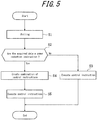
- Operations of the power control device 10a are described using the flowchart in FIG. 5 .
- Operations of the power control devices 10b and 10c are the same as operations of the power control device 10a, and hence a description thereof is omitted.
- the power control device 10a is described as periodically acquiring the control instruction effect information from the EMS server 20, and the control instruction effect information is described as having been stored in the storage unit 101 in advance.
- the instruction acquisition unit 102 acquires a control instruction or a power reduction instruction from the EMS server 20 by polling (step S1).
- control unit 104 determines whether the data acquired by the instruction acquisition unit 102 by polling are a power reduction instruction (step S2). When the data acquired by polling are not a power reduction instruction, processing proceeds to step S3, whereas when the data acquired by polling are a power reduction instruction, processing proceeds to step S4.
- the control unit 104 executes the control instruction acquired by polling (step S3). In other words, the control unit 104 instructs the designated load device to perform control corresponding to the designated operation. Processing then terminates.
- control unit 104 causes the control instruction creation unit 103 to create a combination of control instructions. Based on the predicted power reduction amount included in the control instruction effect information, the control instruction creation unit 103 creates a combination of control instructions that satisfies the power reduction instruction acquired from the EMS server 20 (step S4).
- control unit 104 executes the control instructions in the combination of control instructions created by the control instruction creation unit 103 (step S5). Processing then terminates.
- the power control device 10a autonomously creates a control instruction. Therefore, for example when uniformly reducing power within the EMS server's management area, an increase in the processing load on the EMS server can be suppressed when simultaneously controlling the load devices belonging to a plurality of power control devices. Furthermore, the power reduction instruction alone suffices for communication between the power control device 10a and the EMS server 20, in which case an increase in communication traffic between the EMS server and the power control device can be suppressed.
- control unit 104 may update the predicted power reduction amount included in the control instruction effect information stored in the storage unit 101.
- the control instruction creation unit 103 creates a more accurate combination of control instructions that satisfies the power reduction instruction acquired from the EMS server 20.
- control unit 104 may transmit the control instruction effect information updated in this way to the EMS server 20.
- the EMS server 20 can create more accurate control instructions based on newer control instruction effect information.
- control instruction effect information stored in the storage unit 101 may be a portion of the control instruction effect information stored in the memory 204 of the EMS server 20. Specifically, among the control instruction effect information stored in the memory 204 of the EMS server 20, it is possible for example to store only the control instruction effect information recorded within the past two weeks in the storage unit 101. Furthermore, in this case, in addition to the control instruction effect information recorded within the past two weeks, control instruction effect information pertaining to control instructions with a large effect may be stored as necessary. Control instruction effect information or the like pertaining to instruction information that might occur during a special event, such as a typhoon, may also be stored.
- the present embodiment describes an example in which the power control device 10a periodically acquires the control instruction effect information from the EMS server 20, yet this example is not limiting.
- the power control device 10a may create and update the control instruction effect information based on the power reduction amount due to execution of the control instruction.
- control instruction effect information includes control instructions and a predicted power reduction amount for each of the control instructions, yet this example is not limiting.
- the control instruction effect information may further include a response time for each control instruction.
- FIG. 6 illustrates an example of control instruction effect information that includes the response time.
- the control instruction effect information for example includes a control instruction "raise temperature setting of air conditioner by x°C", a predicted power reduction amount of "400 W”, and a response time of "1 min”.
- the control unit 104 calculates a demand remaining time based on the time at which the instruction acquisition unit acquired the power reduction instruction and on the start of the demand time period from output of the demand management device 17. Based on the demand remaining time and on the response time included in the control instruction effect information, the control instruction creation unit 103 creates a combination of control instructions that satisfies the power reduction instruction. For example, when the demand remaining time is less than two minutes, the effect of control instructions such as "turn air conditioner off" or "lower temperature setting of refrigerator” would be too late even if these control instructions were executed during the demand remaining time. Therefore, the control instruction creation unit 103 excludes these control instructions when creating the combination of control instructions that satisfies the power reduction instruction.
- the power control device 10a can create a more accurate combination of control instructions that satisfies the power reduction instruction by also taking the response time of the control instructions into consideration.
Description
- This application claims priority to and the benefit of Japanese Patent Application No.
2012-156006 filed July 11, 2012 - The present invention relates to a power control device, a power control method, and a power control system that control load devices based on control instructions from a server.
- In recent years, a system has been proposed for controlling various devices from a remote location over the Internet (see Patent Literature 1). In order for a server to control devices directly in the context of device control over a network such as the Internet, it is necessary to assign each device a unique identification number, such as a global IP address, that uniquely specifies a device that is the target of control. As compared to the number of devices that are the target of control, the number of unique identification numbers is limited. Hence, assigning a unique identification number to every control device might deplete the supply of identification numbers.
- A system has therefore been proposed whereby when controlling devices over a network such as the Internet, a local control device accesses a server and reads a control instruction from the server, and based on the read control instruction, a local power control device controls load devices (see Patent Literature 2). In such a configuration where a local control device acquires control instructions by polling in order to control devices, assigning a unique identification number to each device is not necessary.
-
- Patent Literature 1:
JP 2007-336180 A - Patent Literature 2:
JP 2009-260913 A -
WO 2010/065198 A2 discloses a power reduction system having a power savings compensation module which is configured to determine an aggregate compensation and for providing an aggregate energy reduction induced by a power reduction device in response to receiving power status messages transmitted by a power grid status module. -
US 2012/0150359 A1 discloses a computer-based electrical power management and allocation system is provided that collects demand for electric power usage and allocates electric power supply in satisfaction thereof. A load control server is used to collect and schedule electrical power start requests according to policies established by either or both of the electric power consumers and electric power suppliers. The energy system collects electrical power start requests and holds them in a reservation pool for later satisfaction according to prescribed customer and supplier policies and according to an overall optimization criterion of the energy system. Start messages are then subsequently issued to begin device operation once the energy system's operational criterion is relaxed and the devices are then removed from the reservation pool. Similar queuing for later satisfaction may also be applied to the distribution of other utilities, such as water, natural gas, or guaranteed interne bandwidth. - Conventionally, however, a server creates an optimal combination of control instructions for each power control device, and each power control device controls load devices based on the combination of control instructions. Therefore, for example when uniformly reducing power within the server's management area, the processing load on the server increases when simultaneously controlling the load devices belonging to a plurality of power control devices, which may cause processing delays.
- Furthermore, since a combination of a plurality of control instructions is included in the information transmitted from the server to each power control device, communication traffic increases, and a delay may occur in processing for communication.
- The present invention has been conceived in light of the above problems and provides a power control device, a power control method, and a power control system that, for example when uniformly reducing power within the server's management area, can suppress an increase in the processing load on the server when simultaneously controlling the load devices belonging to a plurality of power control devices and that can suppress an increase in communication traffic between the server and the power control device.
- In order to resolve the above problems, a power control device according to the present invention includes: a storage unit configured to store control instruction effect information including a plurality of control instructions for load devices possessed by a consumer's facility and a predicted power reduction amount for each of the plurality of control instructions; an instruction acquisition unit configured to acquire a power reduction instruction from a server; a control instruction creation unit configured to create a combination of some or all of the plurality of control instructions that satisfies the power reduction instruction based on the predicted power reduction amount included in the control instruction effect information; and a control unit configured to execute the some or all of the plurality of control instructions in the combination.
- In the power control device according to the present invention, when the instruction acquisition unit acquires a specific operation instruction for a load device from the server, the power control device may instruct a designated load device to perform control in accordance with a designated operation.
- In the power control device according to the present invention, the control instruction effect information may further include a response time for each control instruction, and the control instruction creation unit may create the combination of some or all of the plurality of control instructions that satisfies the power reduction instruction based on a demand remaining time calculated from a time at which the instruction acquisition unit acquired the power reduction instruction and on the response time included in the control instruction effect information.
- In the power control device according to the present invention, the demand remaining time may be a remaining time within a certain standard time period used in a contractual power agreement.
- In the power control device according to the present invention, the power control device may acquire the control instruction effect information from the server and store the control instruction effect information in the storage unit.
- In the power control device according to the present invention, each of the plurality of control instructions may be ranked by priority, and the control instruction creation unit may create the combination of some or all of the plurality of control instructions that satisfies the power reduction instruction from a combination of control instructions having high priority among control instructions related to load devices in operation.
- A power control method according to the present invention includes the steps of: storing control instruction effect information including a plurality of control instructions and a predicted power reduction amount for each of the plurality of control instructions; acquiring a power reduction instruction from a server; creating a combination of some or all of the plurality of control instructions that satisfies the power reduction instruction based on the predicted power reduction amount included in the control instruction effect information; and executing the some or all of the plurality of control instructions in the combination.
- A power control system according to the present invention includes: a power control device; and a server, the server creating a power reduction instruction, the power control device storing control instruction effect information including a plurality of control instructions and a predicted power reduction amount for each of the plurality of control instructions, the power control device acquiring the power reduction instruction from the server and creating a combination of some or all of the plurality of control instructions that satisfies the power reduction instruction based on the predicted power reduction amount included in the control instruction effect information; and the power control device executing the some or all of the plurality of control instructions in the combination.
- According to the power control device, power control method, and power control system of the present invention, for example when uniformly reducing power within the server's management area, it is possible to suppress an increase in the processing load on the server when simultaneously controlling the load devices belonging to a plurality of power control devices and to suppress an increase in communication traffic between the server and the power control device.
- The scope of the invention is defined by the appended claims. Any reference to "embodiment(s)", "example(s)" or "aspect(s) of the invention" in this description not falling under the scope of the claims should be interpreted as illustrative example(s) for understanding the invention.
- The present invention will be further described below with reference to the accompanying drawings, wherein:
-
FIG. 1 schematically illustrates the structure of a power control system according to an embodiment of the present invention; -
FIG. 2 is a functional block diagram of devices located within the same LAN; -
FIG. 3 is a functional block diagram of a power control device according to an embodiment of the present invention; -
FIG. 4 is an example of control instruction effect information according to an embodiment of the present invention; -
FIG. 5 is a flowchart of operations by a power control device according to an embodiment of the present invention; and -
FIG. 6 is a modification to the control instruction effect information according to an embodiment of the present invention. - The following describes an embodiment of the present invention.
- First, a power control system according to an embodiment of the present invention is described.
FIG. 1 is a communication system structure diagram schematically illustrating the structure of a power control system according to an embodiment of the present invention. - As illustrated in
FIG. 1 , the power control system includes a plurality ofpower control devices 10a to 10c, a plurality ofuser terminals 11a to 11c, and an Energy Management System (EMS)server 20.FIG. 1 illustrates an example with three each of the power control devices and the user terminals, yet this example is not limiting. Two of each may be included, as may four or more of each. - The plurality of
power control devices 10a to 10c, the plurality ofuser terminals 11a to 11c, and theEMS server 20 are connected over the Internet 30 and exchange signals for data, control instructions, and the like. Thepower control device 10a and theuser terminal 11a, thepower control device 10b and theuser terminal 11b, and thepower control device 10c and theuser terminal 11c are respectively located in independent Local Area Networks (LANs) 40a to 40c. - The
power control devices 10a to 10c are each, for example, an EMS Gateway. Thepower control devices 10a to 10c periodically transmit a measured value, such as the power consumption detected by the below-described sensor, to theEMS server 20. By polling, each of thepower control devices 10a to 10c acquires, from theEMS server 20, control instructions for the load devices located within the one of theLANs 40a to 40c to which the power control device belongs. Based on the control instructions received from theEMS server 20, each of thepower control devices 10a to 10c controls the load devices located within the one of theLANs 40a to 40c to which the power control device belongs. - Each of the
user terminals 11a to 11c includes a display device and can display the measured value measured by the sensor located in the one of theLANs 40a to 40c to which the user terminal belongs as well as the operation status of the load devices located in that LAN. When displaying the measured value and the control status, theuser terminals 11a to 11c acquire data from theEMS server 20 by HTTP, and the web browser on each of theuser terminals 11a to 11c creates a measured value display page. Each of theuser terminals 11a to 11c also issues control instructions to the load devices in the one of theLANs 40a to 40c to which the user terminal belongs. The issuing of control instructions is based on detection of user operation on a device control page configured by the web browser. Theuser terminals 11a to 11c transmit the issued control instructions to theEMS server 20. - The
EMS server 20 receives and stores the measured values transmitted from thepower control devices 10a to 10c. The EMSserver 20 also receives the control instructions issued by theuser terminals 11a to 11c. Additionally, theEMS server 20 creates a control instruction for each load device. The received control instruction and the created control instruction are read by thepower control devices 10a to 10c by polling. TheEMS server 20 also receives and updates registration of sensor information located in the LANs 40a to 40c. - Furthermore, for example when uniformly reducing power within the EMS server's management area, instead of a control instruction for each load device, the
EMS server 20 creates an instruction for the total amount by which power is to be reduced in eachLAN 40a to 40c (power reduction instruction). The power reduction instruction is, for example, "reduce by 2 kW or more". This power reduction instruction is read by each of thepower control devices 10a to 10c by polling. - The
EMS server 20 includes adata collector 201, acontroller 202, acontroller queue 203, and amemory 204. - The
data collector 201 periodically collects and stores or updates measured values and sensor registration information. - The
controller 202 creates the control instruction for each load device with a variety of algorithms in order to achieve a variety of purposes. Thecontroller 202 also creates the power reduction instruction. Thecontroller queue 203 stores the control instructions received from theuser terminals 11a to 11c, and the control instructions and power reduction instructions created by thecontroller 202. - The
memory 204 stores a variety of data used by thecontroller 202 to create the control instructions. For example, thememory 204 stores control instruction effect information that includes a predicted power reduction amount for each control instruction. Based on the control instruction effect information, thecontroller 202 can create an appropriate combination of control instructions. The predicted power reduction amount corresponding to each control instruction is created and updated by receiving, from thepower control devices 10a to 10c, the actual results for past power reduction values corresponding to the control instruction. - Next, the transmission of measured values and the control of load devices by the
power control devices 10a to 10c are described.FIG. 2 is a functional block diagram of devices located in theLAN 40a, ademand management device 17, and apower meter 18. Functional block diagrams for devices located in theLANs LAN 40a, thedemand management device 17, and thepower meter 18, and hence a description thereof is omitted. - A
first sensor 12, asensor management unit 13, asecond sensor 14, athird sensor 19,load devices power control device 10a, and theuser terminal 11a are located in theLAN 40a. Thepower control device 10a is connected to thedemand management device 17 and thepower meter 18.FIG. 2 illustrates an example with two load devices, yet this example is not limiting. There may be one load device, or three or more. - The
first sensor 12 is any sensor such as a current sensor, power sensor, temperature sensor, or illumination sensor and detects a measured value related to the drive status of theload devices LAN 40a. - The
sensor management unit 13 detects the measured value from thefirst sensor 12. Thesensor management unit 13 communicates periodically with thepower control device 10a by a standard protocol such as ZigBee (registered trademark) Smart Energy Profile 2.0 (SEP 2.0) or Echonet (registered trademark). - The
second sensor 14 is any sensor such as a current sensor, power sensor, temperature sensor, or illumination sensor and detects a measured value related to the drive status of theload devices LAN 40a. Unlike thefirst sensor 12, the second sensor communicates with thepower control device 10a by a unique protocol. - The
third sensor 19 is any sensor such as a current sensor, power sensor, temperature sensor, or illumination sensor and detects a measured value related to the drive status of theload devices LAN 40a. Unlike thefirst sensor 12 and thesecond sensor 14, thethird sensor 19 communicates directly with thepower control device 10a by a standard protocol such as SEP 2.0 or Echonet (registered trademark). - The
load devices load devices load devices load devices power control device 10a by a standard protocol such as SEP 2.0 or Echonet (registered trademark). - As described above, the
power control device 10a can communicate with thesensor management unit 13 and thesecond sensor 14 and periodically transmits the measured values from thefirst sensor 12 and thesecond sensor 14 to theEMS server 20 over theInternet 30. As also described above, by polling, thepower control device 10a acquires, from theEMS server 20, control instructions for theload devices LAN 40a to which thepower control device 10a belongs, and based on the control instructions, controls the operation status of theload devices - The
power control device 10a recognizes the start of a demand time period from the output of thedemand management device 17. As described below, thepower control device 10a also acquires, from the output of thedemand management device 17, the current value of power consumption by all of the load devices (including theload devices 15 and 16) within theLAN 40a during the current demand time period. - As described above, the
user terminal 11a displays the measured values from thefirst sensor 12 and thesecond sensor 14 that are located in theLAN 40a to which theuser terminal 11a belongs and displays the operation status of theload devices user terminal 11a allows for direct control instructions for theload devices - The
power meter 18 measures the cumulative power consumption for each store during the demand time period (demand power (power usage)). The demand time period is a standard time period used in a contractual power agreement between the business operator (consumer) that runs a store or the like and the power company. For example, when the demand time period is 30 minutes and the contract power is 300 kW, the contract is considered to be fulfilled as long as the 30 minute average is less than 300 kW, even if the power consumption temporarily exceeds 300 kW during any demand time period. Thepower meter 18 resets the demand power at the start of a demand time period and measures the demand power from the start of the demand time period to the present. By measuring the power consumption at the end of a demand time period, the demand power during that demand time period can be measured. Thedemand management device 17 reads a pulse output by thepower meter 18 and outputs the read pulse to thepower control device 10a. Note that thepower meter 18 and thedemand management device 17 are not only provided for thepower control device 10a in theLAN 40a, but also for the power control devices in theLANs -
FIG. 3 is a detailed functional block diagram of thepower control device 10a according to an embodiment of the present invention. Thepower control devices - The
power control device 10a includes astorage unit 101, aninstruction acquisition unit 102, a controlinstruction creation unit 103, and acontrol unit 104. - The
storage unit 101 stores control instruction effect information that includes a plurality of control instructions and a predicted power reduction amount for each of the control instructions. The control instruction effect information is the same as the control instruction effect information stored in thememory 204 of theEMS server 20. Thepower control device 10a periodically acquires the control instruction effect information from theEMS server 20 and stores the control instruction effect information in thestorage unit 101. -
FIG. 4 illustrates an example of the control instruction effect information.FIG. 4 shows the control instruction effect information in table format. For example, the control instruction effect information includes a control instruction "raise temperature setting of air conditioner by x°C" and a predicted power reduction amount of "400 W" for this control instruction. - The
instruction acquisition unit 102 acquires a control instruction or a power reduction instruction from theEMS server 20 by polling. When theinstruction acquisition unit 102 acquires a power reduction instruction by polling, then based on the predicted power reduction amount included in the control instruction effect information, the controlinstruction creation unit 103 creates a combination of control instructions that satisfies the power reduction instruction acquired from theEMS server 20. For example, if the power reduction instruction is "reduce by 2 kW or more", then based on the control instruction effect information illustrated inFIG. 4 , the controlinstruction creation unit 103 extracts control instructions and creates a combination so that the total of the predicted power reduction amounts is 2 kW or more. For example, the controlinstruction creation unit 103 creates a combination of the control instructions "raise temperature setting of air conditioner by z°C", "lower illumination intensity of lighting appliance", and "lower temperature setting of refrigerator". The total of the predicted power reduction amounts for these control instructions is 2.2 kW (1200 W + 500 W + 500 W), thus satisfying the power reduction instruction. The actual extraction of control instructions may be random, yet the control instructions are preferably ranked by priority from the control instruction with the least effect on the consumer and extracted in order of priority to satisfy the power reduction instruction. The controlinstruction creation unit 103 also preferably executes processing to determine whether each load device is in operation, extract control instructions that are for load devices in operation and that have high priority, and determine the minimum combination that satisfies the required power reduction amount. - The
control unit 104 executes a variety of control pertaining to thepower control device 10a. Specifically, thecontrol unit 104 determines whether the data acquired by theinstruction acquisition unit 102 by polling are a power reduction instruction. When the data are a power reduction instruction, thecontrol unit 104 causes the controlinstruction creation unit 103 to create a combination of control instructions. Thecontrol unit 104 executes a control instruction acquired by polling. Thecontrol unit 104 also executes the control instructions in the combination of control instructions created by the controlinstruction creation unit 103. - Next, operations of the
power control device 10a according to an embodiment of the present invention are described using the flowchart inFIG. 5 . Operations of thepower control devices power control device 10a, and hence a description thereof is omitted. Thepower control device 10a is described as periodically acquiring the control instruction effect information from theEMS server 20, and the control instruction effect information is described as having been stored in thestorage unit 101 in advance. - First, the
instruction acquisition unit 102 acquires a control instruction or a power reduction instruction from theEMS server 20 by polling (step S1). - Next, the
control unit 104 determines whether the data acquired by theinstruction acquisition unit 102 by polling are a power reduction instruction (step S2). When the data acquired by polling are not a power reduction instruction, processing proceeds to step S3, whereas when the data acquired by polling are a power reduction instruction, processing proceeds to step S4. - When the data acquired by polling are not a power reduction instruction, i.e. when the acquired data are a control instruction that directly designates a load device and provides an instruction for a specific operation for the designated load device (a specific temperature setting, power ON/OFF, or the like), the
control unit 104 executes the control instruction acquired by polling (step S3). In other words, thecontrol unit 104 instructs the designated load device to perform control corresponding to the designated operation. Processing then terminates. - On the other hand, when the data acquired by polling are a power reduction instruction, the
control unit 104 causes the controlinstruction creation unit 103 to create a combination of control instructions. Based on the predicted power reduction amount included in the control instruction effect information, the controlinstruction creation unit 103 creates a combination of control instructions that satisfies the power reduction instruction acquired from the EMS server 20 (step S4). - Next, the
control unit 104 executes the control instructions in the combination of control instructions created by the control instruction creation unit 103 (step S5). Processing then terminates. - In this way, according to the present invention, when acquiring a power reduction instruction from the
EMS server 20, thepower control device 10a autonomously creates a control instruction. Therefore, for example when uniformly reducing power within the EMS server's management area, an increase in the processing load on the EMS server can be suppressed when simultaneously controlling the load devices belonging to a plurality of power control devices. Furthermore, the power reduction instruction alone suffices for communication between thepower control device 10a and theEMS server 20, in which case an increase in communication traffic between the EMS server and the power control device can be suppressed. - Here, after step S5, based on the power reduction amount due to execution of the control instructions, the
control unit 104 may update the predicted power reduction amount included in the control instruction effect information stored in thestorage unit 101. With this configuration, based on the newer predicted power reduction amount included in the control instruction effect information, the controlinstruction creation unit 103 creates a more accurate combination of control instructions that satisfies the power reduction instruction acquired from theEMS server 20. - Furthermore, the
control unit 104 may transmit the control instruction effect information updated in this way to theEMS server 20. With this configuration, theEMS server 20 can create more accurate control instructions based on newer control instruction effect information. - Here, the control instruction effect information stored in the
storage unit 101 may be a portion of the control instruction effect information stored in thememory 204 of theEMS server 20. Specifically, among the control instruction effect information stored in thememory 204 of theEMS server 20, it is possible for example to store only the control instruction effect information recorded within the past two weeks in thestorage unit 101. Furthermore, in this case, in addition to the control instruction effect information recorded within the past two weeks, control instruction effect information pertaining to control instructions with a large effect may be stored as necessary. Control instruction effect information or the like pertaining to instruction information that might occur during a special event, such as a typhoon, may also be stored. - The present embodiment describes an example in which the
power control device 10a periodically acquires the control instruction effect information from theEMS server 20, yet this example is not limiting. When thepower control device 10a executes a control instruction, thepower control device 10a may create and update the control instruction effect information based on the power reduction amount due to execution of the control instruction. - In the present embodiment, the control instruction effect information includes control instructions and a predicted power reduction amount for each of the control instructions, yet this example is not limiting. The control instruction effect information may further include a response time for each control instruction.
FIG. 6 illustrates an example of control instruction effect information that includes the response time. As illustrated inFIG. 6 , the control instruction effect information for example includes a control instruction "raise temperature setting of air conditioner by x°C", a predicted power reduction amount of "400 W", and a response time of "1 min". - Specifically, in this case, the
control unit 104 calculates a demand remaining time based on the time at which the instruction acquisition unit acquired the power reduction instruction and on the start of the demand time period from output of thedemand management device 17. Based on the demand remaining time and on the response time included in the control instruction effect information, the controlinstruction creation unit 103 creates a combination of control instructions that satisfies the power reduction instruction. For example, when the demand remaining time is less than two minutes, the effect of control instructions such as "turn air conditioner off" or "lower temperature setting of refrigerator" would be too late even if these control instructions were executed during the demand remaining time. Therefore, the controlinstruction creation unit 103 excludes these control instructions when creating the combination of control instructions that satisfies the power reduction instruction. - With this configuration, the
power control device 10a can create a more accurate combination of control instructions that satisfies the power reduction instruction by also taking the response time of the control instructions into consideration. -
- 10a to 10c: Power control device
- 101: Storage unit
- 102: Instruction acquisition unit
- 103: Control instruction creation unit
- 104: Control unit
- 105: Recording unit
- 11a to 11c: User terminal
- 12: First sensor
- 13: Sensor management unit
- 14: Second sensor
- 15 to 16: Load device
- 17: Demand management device
- 18: Power meter
- 19: Third sensor
- 20: EMS server
- 30: Internet
- 40a to 40c: LAN
- 201: Data collector
- 202: Controller
- 203: Controller queue
- 204: Memory
Claims (8)
- A power control device (10) in a local area network, the device comprising:a storage unit (101) configured to store control instruction effect information including a plurality of control instructions for load devices possessed by a consumer's facility and a predicted power reduction amount for each of the plurality of control instructions;an instruction acquisition unit (102) configured to acquire a power reduction instruction from an energy management system server (20) configured to communicate with a plurality of power control devices respectively located in a plurality of independent local area networks;a control instruction creation unit (103) configured to extract control instructions and create a combination of some or all of the extracted control instructions which have predicted power reduction amounts that satisfy, in total, the power reduction instruction, based on the predicted power reduction amount included in the control instruction effect information; anda control unit (104) configured to execute the some or all of the plurality of control instructions in the combination and, based on the power reduction amount due to execution of the control instructions, update the predicted power reduction amount included in the control instruction effect information stored in the storage unit (101).
- The power control device (10) according to claim 1, wherein when the instruction acquisition unit (102) acquires a specific operation instruction for a load device from the energy management system server (20), the power control device instructs a designated load device to perform control in accordance with a designated operation.
- The power control device (10) according to claim 1, wherein
the control instruction effect information further includes a response time for each control instruction, and
the control instruction creation unit (103) creates the combination of some or all of the plurality of control instructions that satisfies the power reduction instruction based on a demand remaining time calculated from a time at which the instruction acquisition unit acquired the power reduction instruction and on the response time included in the control instruction effect information. - The power control device (10) according to claim 3, wherein the demand remaining time is a remaining time within a certain standard time period used in a contractual power agreement.
- The power control device (10) according to claim 1, wherein the power control device (10) acquires the control instruction effect information from the energy management system server (20) and stores the control instruction effect information in the storage unit.
- The power control device (10) according to claim 1, wherein
each of the plurality of control instructions is ranked by priority, and
the control instruction creation unit (103) creates the combination of some or all of the plurality of control instructions that satisfies the power reduction instruction from a combination of control instructions having high priority among control instructions related to load devices in operation. - A power control method of a power control device in a local area network, the method including steps of:storing control instruction effect information including a plurality of control instructions and a predicted power reduction amount for each of the plurality of control instructions;acquiring a power reduction instruction from an energy management system server (20) which communicates with a plurality of power control devices respectively located in a plurality of independent local area networks;extracting control instructions and creating a combination of all of the extracted control instructions which have predicted power reduction amounts that satisfy, in total, the power reduction instruction, based on the predicted power reduction amount included in the control instruction effect information; andexecuting the some or all of the plurality of control instructions in the combination and, based on the power reduction amount due to execution of the control instructions, updating the predicted power reduction amount included in the stored control instruction effect information.
- A power control system comprising:an energy management system server (20) configured to communicate with a plurality of power control devices respectively located in a plurality of independent local area networks; andthe power control device (10) according to claim 1,wherein:the energy management system server (20) is configured to create the power control instruction; andthe instruction acquisition unit (102) of the power control device (10) is configured to acquire the power reduction instruction from the energy management system server (20).
Applications Claiming Priority (2)
| Application Number | Priority Date | Filing Date | Title |
|---|---|---|---|
| JP2012156006A JP6012313B2 (en) | 2012-07-11 | 2012-07-11 | Power control apparatus, power control method, and power control system |
| PCT/JP2013/004269 WO2014010242A1 (en) | 2012-07-11 | 2013-07-10 | Power control device, power control method and power control system |
Publications (3)
| Publication Number | Publication Date |
|---|---|
| EP2874274A1 EP2874274A1 (en) | 2015-05-20 |
| EP2874274A4 EP2874274A4 (en) | 2016-04-27 |
| EP2874274B1 true EP2874274B1 (en) | 2020-10-07 |
Family
ID=49915723
Family Applications (1)
| Application Number | Title | Priority Date | Filing Date |
|---|---|---|---|
| EP13817375.2A Active EP2874274B1 (en) | 2012-07-11 | 2013-07-10 | Power control device, power control method and power control system |
Country Status (4)
| Country | Link |
|---|---|
| US (1) | US20150148977A1 (en) |
| EP (1) | EP2874274B1 (en) |
| JP (1) | JP6012313B2 (en) |
| WO (1) | WO2014010242A1 (en) |
Families Citing this family (2)
| Publication number | Priority date | Publication date | Assignee | Title |
|---|---|---|---|---|
| US10615596B2 (en) * | 2015-09-30 | 2020-04-07 | Siemens Aktiengesellschaft | Systems, methods and apparatus for an improved aggregation engine for a demand response management system |
| JP6637323B2 (en) * | 2016-02-10 | 2020-01-29 | 三菱電機ビルテクノサービス株式会社 | Equipment management device and program |
Family Cites Families (22)
| Publication number | Priority date | Publication date | Assignee | Title |
|---|---|---|---|---|
| US5481140A (en) * | 1992-03-10 | 1996-01-02 | Mitsubishi Denki Kabushiki Kaisha | Demand control apparatus and power distribution control system |
| JP2002320327A (en) * | 2001-04-20 | 2002-10-31 | Mitsubishi Electric Corp | Selective load breaking/closing device and method therefor |
| JP2003116219A (en) * | 2001-10-09 | 2003-04-18 | Nihon Setsubi Kogyo Co Ltd | System and method for controlling quantity of working power, and computer-readable storage medium recording control program for quantity of working power |
| JP2003153347A (en) * | 2001-11-16 | 2003-05-23 | Fujitsu Ltd | Power consumption control method and apparatus for home electric appliance |
| JP2007020260A (en) * | 2005-07-06 | 2007-01-25 | Matsushita Electric Ind Co Ltd | Power supplying system and power supplying service method |
| JP2007236038A (en) * | 2006-02-28 | 2007-09-13 | Sanyo Electric Co Ltd | Demand controller |
| JP2007336180A (en) | 2006-06-14 | 2007-12-27 | Bizline Corp | Remote control system |
| JP2008182840A (en) * | 2007-01-25 | 2008-08-07 | Fuji Xerox Co Ltd | Power control system and program, and image processor |
| US7908116B2 (en) * | 2007-08-03 | 2011-03-15 | Ecofactor, Inc. | System and method for using a network of thermostats as tool to verify peak demand reduction |
| JP5558689B2 (en) | 2008-03-24 | 2014-07-23 | 日本電気株式会社 | REMOTE CONTROL DEVICE, REMOTE CONTROL PROGRAM, REMOTE CONTROL METHOD, AND REMOTE CONTROL SYSTEM |
| US8412654B2 (en) * | 2008-10-08 | 2013-04-02 | Rey Montalvo | Method and system for fully automated energy curtailment |
| CA2745566C (en) * | 2008-12-04 | 2016-01-19 | American Power Conversion Corporation | Energy reduction |
| US20100145884A1 (en) * | 2008-12-04 | 2010-06-10 | American Power Conversion Corporation | Energy savings aggregation |
| US8744638B2 (en) * | 2009-09-11 | 2014-06-03 | General Electric Company | Method and system for demand response in a distribution network |
| JP5646206B2 (en) * | 2010-04-28 | 2014-12-24 | 株式会社東芝 | Power consumption management apparatus and power consumption management method |
| US8938322B2 (en) * | 2010-12-06 | 2015-01-20 | Henrik Westergaard | Apparatus and method for controlling consumer electric power consumption |
| US20120179596A1 (en) * | 2011-01-11 | 2012-07-12 | Kenji Mitsumoto | Power reserve margin trading system and power reserve margin trading method |
| US20120245749A1 (en) * | 2011-03-21 | 2012-09-27 | Nathan Bowman Littrell | Systems and methods for managing an energy distribution network |
| US20120323382A1 (en) * | 2011-06-15 | 2012-12-20 | Expanergy, Llc | Systems and methods to assess and optimize energy usage for a facility |
| US8972071B2 (en) * | 2011-10-27 | 2015-03-03 | General Electric Company | Systems and methods to predict a reduction of energy consumption |
| US20150019037A1 (en) * | 2013-07-11 | 2015-01-15 | Honeywell International Inc. | System having customer defined demand response signals |
| US20160292205A1 (en) * | 2015-03-30 | 2016-10-06 | General Electric Company | System and methods for improved demand response management system (drms) |
-
2012
- 2012-07-11 JP JP2012156006A patent/JP6012313B2/en active Active
-
2013
- 2013-07-10 US US14/410,847 patent/US20150148977A1/en not_active Abandoned
- 2013-07-10 EP EP13817375.2A patent/EP2874274B1/en active Active
- 2013-07-10 WO PCT/JP2013/004269 patent/WO2014010242A1/en active Application Filing
Non-Patent Citations (1)
| Title |
|---|
| None * |
Also Published As
| Publication number | Publication date |
|---|---|
| WO2014010242A1 (en) | 2014-01-16 |
| EP2874274A4 (en) | 2016-04-27 |
| EP2874274A1 (en) | 2015-05-20 |
| US20150148977A1 (en) | 2015-05-28 |
| JP2014017792A (en) | 2014-01-30 |
| JP6012313B2 (en) | 2016-10-25 |
Similar Documents
| Publication | Publication Date | Title |
|---|---|---|
| EP2874263B1 (en) | Server device and electrical power control system | |
| KR101872557B1 (en) | Energy consumption management | |
| CN104221240B (en) | The load curve management method and its control system of low pressure or medium voltage network | |
| EP2214283B1 (en) | Supply-and-demand control system of distributed and coordinated type, for use in power systems | |
| JP6249895B2 (en) | Power control system, method, and power control apparatus | |
| EP2701261A1 (en) | Control device, power control system, and power control method | |
| JP6189949B2 (en) | Controlled apparatus, control apparatus, apparatus control method, and apparatus control system | |
| EP2787598B1 (en) | Power control device, power control system, and power control method | |
| US20120277921A1 (en) | Cross-profile coordination of energy consumption policies | |
| US10243373B2 (en) | Power control system, power control device, server device, and method for controlling power control system | |
| WO2012056551A1 (en) | Communication method of monitoring control system and monitoring control system | |
| EP2874274B1 (en) | Power control device, power control method and power control system | |
| JP6173068B2 (en) | Power suppression method, power management system, and power management program | |
| JP5847650B2 (en) | Energy management system, server device, energy management method and program | |
| JP6072474B2 (en) | Power management apparatus, power control system, and power management method | |
| JP2020522978A (en) | Method and assembly for load management of electrical equipment | |
| WO2017212506A1 (en) | Energy management system, guide server and energy management method | |
| JP5865793B2 (en) | Power control device | |
| JP6555524B2 (en) | Power management system, information device, and program | |
| JP5699104B2 (en) | Power control system used | |
| JP2019075990A (en) | Power storage control system, instruction control device, power storage control device, power storage control method and program | |
| JP2017022993A (en) | Power control system, power control method, and power control device | |
| KR20110040584A (en) | Method of controlling home network device and apparatus for the same | |
| WO2015045156A1 (en) | Power amount control device, power amount control method, power amount control system, and appliance control device | |
| JP2014018044A (en) | Power control system and method of controlling the same |
Legal Events
| Date | Code | Title | Description |
|---|---|---|---|
| PUAI | Public reference made under article 153(3) epc to a published international application that has entered the european phase |
Free format text: ORIGINAL CODE: 0009012 |
|
| 17P | Request for examination filed |
Effective date: 20141223 |
|
| AK | Designated contracting states |
Kind code of ref document: A1 Designated state(s): AL AT BE BG CH CY CZ DE DK EE ES FI FR GB GR HR HU IE IS IT LI LT LU LV MC MK MT NL NO PL PT RO RS SE SI SK SM TR |
|
| AX | Request for extension of the european patent |
Extension state: BA ME |
|
| DAX | Request for extension of the european patent (deleted) | ||
| RA4 | Supplementary search report drawn up and despatched (corrected) |
Effective date: 20160330 |
|
| RIC1 | Information provided on ipc code assigned before grant |
Ipc: H02J 3/14 20060101ALI20160322BHEP Ipc: G05F 1/66 20060101ALI20160322BHEP Ipc: H02J 13/00 20060101AFI20160322BHEP |
|
| STAA | Information on the status of an ep patent application or granted ep patent |
Free format text: STATUS: EXAMINATION IS IN PROGRESS |
|
| 17Q | First examination report despatched |
Effective date: 20170804 |
|
| GRAP | Despatch of communication of intention to grant a patent |
Free format text: ORIGINAL CODE: EPIDOSNIGR1 |
|
| STAA | Information on the status of an ep patent application or granted ep patent |
Free format text: STATUS: GRANT OF PATENT IS INTENDED |
|
| INTG | Intention to grant announced |
Effective date: 20200515 |
|
| GRAS | Grant fee paid |
Free format text: ORIGINAL CODE: EPIDOSNIGR3 |
|
| GRAA | (expected) grant |
Free format text: ORIGINAL CODE: 0009210 |
|
| STAA | Information on the status of an ep patent application or granted ep patent |
Free format text: STATUS: THE PATENT HAS BEEN GRANTED |
|
| AK | Designated contracting states |
Kind code of ref document: B1 Designated state(s): AL AT BE BG CH CY CZ DE DK EE ES FI FR GB GR HR HU IE IS IT LI LT LU LV MC MK MT NL NO PL PT RO RS SE SI SK SM TR |
|
| REG | Reference to a national code |
Ref country code: GB Ref legal event code: FG4D |
|
| REG | Reference to a national code |
Ref country code: CH Ref legal event code: EP Ref country code: AT Ref legal event code: REF Ref document number: 1322195 Country of ref document: AT Kind code of ref document: T Effective date: 20201015 |
|
| REG | Reference to a national code |
Ref country code: DE Ref legal event code: R096 Ref document number: 602013073148 Country of ref document: DE |
|
| REG | Reference to a national code |
Ref country code: IE Ref legal event code: FG4D |
|
| REG | Reference to a national code |
Ref country code: NL Ref legal event code: MP Effective date: 20201007 |
|
| REG | Reference to a national code |
Ref country code: AT Ref legal event code: MK05 Ref document number: 1322195 Country of ref document: AT Kind code of ref document: T Effective date: 20201007 |
|
| PG25 | Lapsed in a contracting state [announced via postgrant information from national office to epo] |
Ref country code: PT Free format text: LAPSE BECAUSE OF FAILURE TO SUBMIT A TRANSLATION OF THE DESCRIPTION OR TO PAY THE FEE WITHIN THE PRESCRIBED TIME-LIMIT Effective date: 20210208 Ref country code: NL Free format text: LAPSE BECAUSE OF FAILURE TO SUBMIT A TRANSLATION OF THE DESCRIPTION OR TO PAY THE FEE WITHIN THE PRESCRIBED TIME-LIMIT Effective date: 20201007 Ref country code: NO Free format text: LAPSE BECAUSE OF FAILURE TO SUBMIT A TRANSLATION OF THE DESCRIPTION OR TO PAY THE FEE WITHIN THE PRESCRIBED TIME-LIMIT Effective date: 20210107 Ref country code: FI Free format text: LAPSE BECAUSE OF FAILURE TO SUBMIT A TRANSLATION OF THE DESCRIPTION OR TO PAY THE FEE WITHIN THE PRESCRIBED TIME-LIMIT Effective date: 20201007 Ref country code: RS Free format text: LAPSE BECAUSE OF FAILURE TO SUBMIT A TRANSLATION OF THE DESCRIPTION OR TO PAY THE FEE WITHIN THE PRESCRIBED TIME-LIMIT Effective date: 20201007 Ref country code: GR Free format text: LAPSE BECAUSE OF FAILURE TO SUBMIT A TRANSLATION OF THE DESCRIPTION OR TO PAY THE FEE WITHIN THE PRESCRIBED TIME-LIMIT Effective date: 20210108 |
|
| REG | Reference to a national code |
Ref country code: LT Ref legal event code: MG4D |
|
| PG25 | Lapsed in a contracting state [announced via postgrant information from national office to epo] |
Ref country code: PL Free format text: LAPSE BECAUSE OF FAILURE TO SUBMIT A TRANSLATION OF THE DESCRIPTION OR TO PAY THE FEE WITHIN THE PRESCRIBED TIME-LIMIT Effective date: 20201007 Ref country code: SE Free format text: LAPSE BECAUSE OF FAILURE TO SUBMIT A TRANSLATION OF THE DESCRIPTION OR TO PAY THE FEE WITHIN THE PRESCRIBED TIME-LIMIT Effective date: 20201007 Ref country code: LV Free format text: LAPSE BECAUSE OF FAILURE TO SUBMIT A TRANSLATION OF THE DESCRIPTION OR TO PAY THE FEE WITHIN THE PRESCRIBED TIME-LIMIT Effective date: 20201007 Ref country code: IS Free format text: LAPSE BECAUSE OF FAILURE TO SUBMIT A TRANSLATION OF THE DESCRIPTION OR TO PAY THE FEE WITHIN THE PRESCRIBED TIME-LIMIT Effective date: 20210207 Ref country code: BG Free format text: LAPSE BECAUSE OF FAILURE TO SUBMIT A TRANSLATION OF THE DESCRIPTION OR TO PAY THE FEE WITHIN THE PRESCRIBED TIME-LIMIT Effective date: 20210107 Ref country code: AT Free format text: LAPSE BECAUSE OF FAILURE TO SUBMIT A TRANSLATION OF THE DESCRIPTION OR TO PAY THE FEE WITHIN THE PRESCRIBED TIME-LIMIT Effective date: 20201007 Ref country code: ES Free format text: LAPSE BECAUSE OF FAILURE TO SUBMIT A TRANSLATION OF THE DESCRIPTION OR TO PAY THE FEE WITHIN THE PRESCRIBED TIME-LIMIT Effective date: 20201007 |
|
| PG25 | Lapsed in a contracting state [announced via postgrant information from national office to epo] |
Ref country code: HR Free format text: LAPSE BECAUSE OF FAILURE TO SUBMIT A TRANSLATION OF THE DESCRIPTION OR TO PAY THE FEE WITHIN THE PRESCRIBED TIME-LIMIT Effective date: 20201007 |
|
| REG | Reference to a national code |
Ref country code: DE Ref legal event code: R097 Ref document number: 602013073148 Country of ref document: DE |
|
| PG25 | Lapsed in a contracting state [announced via postgrant information from national office to epo] |
Ref country code: LT Free format text: LAPSE BECAUSE OF FAILURE TO SUBMIT A TRANSLATION OF THE DESCRIPTION OR TO PAY THE FEE WITHIN THE PRESCRIBED TIME-LIMIT Effective date: 20201007 Ref country code: RO Free format text: LAPSE BECAUSE OF FAILURE TO SUBMIT A TRANSLATION OF THE DESCRIPTION OR TO PAY THE FEE WITHIN THE PRESCRIBED TIME-LIMIT Effective date: 20201007 Ref country code: SK Free format text: LAPSE BECAUSE OF FAILURE TO SUBMIT A TRANSLATION OF THE DESCRIPTION OR TO PAY THE FEE WITHIN THE PRESCRIBED TIME-LIMIT Effective date: 20201007 Ref country code: EE Free format text: LAPSE BECAUSE OF FAILURE TO SUBMIT A TRANSLATION OF THE DESCRIPTION OR TO PAY THE FEE WITHIN THE PRESCRIBED TIME-LIMIT Effective date: 20201007 Ref country code: CZ Free format text: LAPSE BECAUSE OF FAILURE TO SUBMIT A TRANSLATION OF THE DESCRIPTION OR TO PAY THE FEE WITHIN THE PRESCRIBED TIME-LIMIT Effective date: 20201007 Ref country code: SM Free format text: LAPSE BECAUSE OF FAILURE TO SUBMIT A TRANSLATION OF THE DESCRIPTION OR TO PAY THE FEE WITHIN THE PRESCRIBED TIME-LIMIT Effective date: 20201007 |
|
| PLBE | No opposition filed within time limit |
Free format text: ORIGINAL CODE: 0009261 |
|
| STAA | Information on the status of an ep patent application or granted ep patent |
Free format text: STATUS: NO OPPOSITION FILED WITHIN TIME LIMIT |
|
| PG25 | Lapsed in a contracting state [announced via postgrant information from national office to epo] |
Ref country code: DK Free format text: LAPSE BECAUSE OF FAILURE TO SUBMIT A TRANSLATION OF THE DESCRIPTION OR TO PAY THE FEE WITHIN THE PRESCRIBED TIME-LIMIT Effective date: 20201007 |
|
| 26N | No opposition filed |
Effective date: 20210708 |
|
| PG25 | Lapsed in a contracting state [announced via postgrant information from national office to epo] |
Ref country code: IT Free format text: LAPSE BECAUSE OF FAILURE TO SUBMIT A TRANSLATION OF THE DESCRIPTION OR TO PAY THE FEE WITHIN THE PRESCRIBED TIME-LIMIT Effective date: 20201007 Ref country code: AL Free format text: LAPSE BECAUSE OF FAILURE TO SUBMIT A TRANSLATION OF THE DESCRIPTION OR TO PAY THE FEE WITHIN THE PRESCRIBED TIME-LIMIT Effective date: 20201007 |
|
| PG25 | Lapsed in a contracting state [announced via postgrant information from national office to epo] |
Ref country code: SI Free format text: LAPSE BECAUSE OF FAILURE TO SUBMIT A TRANSLATION OF THE DESCRIPTION OR TO PAY THE FEE WITHIN THE PRESCRIBED TIME-LIMIT Effective date: 20201007 |
|
| REG | Reference to a national code |
Ref country code: DE Ref legal event code: R119 Ref document number: 602013073148 Country of ref document: DE |
|
| REG | Reference to a national code |
Ref country code: CH Ref legal event code: PL |
|
| GBPC | Gb: european patent ceased through non-payment of renewal fee |
Effective date: 20210710 |
|
| PG25 | Lapsed in a contracting state [announced via postgrant information from national office to epo] |
Ref country code: MC Free format text: LAPSE BECAUSE OF FAILURE TO SUBMIT A TRANSLATION OF THE DESCRIPTION OR TO PAY THE FEE WITHIN THE PRESCRIBED TIME-LIMIT Effective date: 20201007 |
|
| REG | Reference to a national code |
Ref country code: BE Ref legal event code: MM Effective date: 20210731 |
|
| PG25 | Lapsed in a contracting state [announced via postgrant information from national office to epo] |
Ref country code: LI Free format text: LAPSE BECAUSE OF NON-PAYMENT OF DUE FEES Effective date: 20210731 Ref country code: GB Free format text: LAPSE BECAUSE OF NON-PAYMENT OF DUE FEES Effective date: 20210710 Ref country code: DE Free format text: LAPSE BECAUSE OF NON-PAYMENT OF DUE FEES Effective date: 20220201 Ref country code: CH Free format text: LAPSE BECAUSE OF NON-PAYMENT OF DUE FEES Effective date: 20210731 |
|
| PG25 | Lapsed in a contracting state [announced via postgrant information from national office to epo] |
Ref country code: IS Free format text: LAPSE BECAUSE OF FAILURE TO SUBMIT A TRANSLATION OF THE DESCRIPTION OR TO PAY THE FEE WITHIN THE PRESCRIBED TIME-LIMIT Effective date: 20210207 Ref country code: LU Free format text: LAPSE BECAUSE OF NON-PAYMENT OF DUE FEES Effective date: 20210710 Ref country code: FR Free format text: LAPSE BECAUSE OF NON-PAYMENT OF DUE FEES Effective date: 20210731 |
|
| PG25 | Lapsed in a contracting state [announced via postgrant information from national office to epo] |
Ref country code: IE Free format text: LAPSE BECAUSE OF NON-PAYMENT OF DUE FEES Effective date: 20210710 Ref country code: BE Free format text: LAPSE BECAUSE OF NON-PAYMENT OF DUE FEES Effective date: 20210731 |
|
| PG25 | Lapsed in a contracting state [announced via postgrant information from national office to epo] |
Ref country code: HU Free format text: LAPSE BECAUSE OF FAILURE TO SUBMIT A TRANSLATION OF THE DESCRIPTION OR TO PAY THE FEE WITHIN THE PRESCRIBED TIME-LIMIT; INVALID AB INITIO Effective date: 20130710 |
|
| PG25 | Lapsed in a contracting state [announced via postgrant information from national office to epo] |
Ref country code: CY Free format text: LAPSE BECAUSE OF FAILURE TO SUBMIT A TRANSLATION OF THE DESCRIPTION OR TO PAY THE FEE WITHIN THE PRESCRIBED TIME-LIMIT Effective date: 20201007 |