EP2874265B1 - Procédé et système de surveillance et de commande d'une distribution de courant dans un réseau de distribution d'énergie - Google Patents
Procédé et système de surveillance et de commande d'une distribution de courant dans un réseau de distribution d'énergie Download PDFInfo
- Publication number
- EP2874265B1 EP2874265B1 EP13192631.3A EP13192631A EP2874265B1 EP 2874265 B1 EP2874265 B1 EP 2874265B1 EP 13192631 A EP13192631 A EP 13192631A EP 2874265 B1 EP2874265 B1 EP 2874265B1
- Authority
- EP
- European Patent Office
- Prior art keywords
- network
- current
- devices
- measured values
- energy
- Prior art date
- Legal status (The legal status is an assumption and is not a legal conclusion. Google has not performed a legal analysis and makes no representation as to the accuracy of the status listed.)
- Active
Links
- 238000009826 distribution Methods 0.000 title claims description 82
- 238000012544 monitoring process Methods 0.000 title claims description 62
- 238000000034 method Methods 0.000 title claims description 40
- 238000004891 communication Methods 0.000 claims description 43
- 230000005540 biological transmission Effects 0.000 claims description 22
- 238000005259 measurement Methods 0.000 claims description 9
- 238000012806 monitoring device Methods 0.000 claims 1
- 238000010248 power generation Methods 0.000 description 27
- 238000000926 separation method Methods 0.000 description 11
- 230000001276 controlling effect Effects 0.000 description 9
- 238000004146 energy storage Methods 0.000 description 9
- 230000005611 electricity Effects 0.000 description 4
- 238000009434 installation Methods 0.000 description 4
- 238000001514 detection method Methods 0.000 description 3
- 230000008569 process Effects 0.000 description 3
- 238000005265 energy consumption Methods 0.000 description 2
- 238000011156 evaluation Methods 0.000 description 2
- 230000002349 favourable effect Effects 0.000 description 2
- 230000009467 reduction Effects 0.000 description 2
- 230000001105 regulatory effect Effects 0.000 description 2
- 238000003860 storage Methods 0.000 description 2
- 238000013459 approach Methods 0.000 description 1
- 230000008859 change Effects 0.000 description 1
- 230000000052 comparative effect Effects 0.000 description 1
- 230000001419 dependent effect Effects 0.000 description 1
- 238000011161 development Methods 0.000 description 1
- 238000004519 manufacturing process Methods 0.000 description 1
- 238000012546 transfer Methods 0.000 description 1
- 230000007704 transition Effects 0.000 description 1
Images

Classifications
-
- H—ELECTRICITY
- H02—GENERATION; CONVERSION OR DISTRIBUTION OF ELECTRIC POWER
- H02J—CIRCUIT ARRANGEMENTS OR SYSTEMS FOR SUPPLYING OR DISTRIBUTING ELECTRIC POWER; SYSTEMS FOR STORING ELECTRIC ENERGY
- H02J3/00—Circuit arrangements for ac mains or ac distribution networks
- H02J3/38—Arrangements for parallely feeding a single network by two or more generators, converters or transformers
- H02J3/381—Dispersed generators
-
- H—ELECTRICITY
- H02—GENERATION; CONVERSION OR DISTRIBUTION OF ELECTRIC POWER
- H02J—CIRCUIT ARRANGEMENTS OR SYSTEMS FOR SUPPLYING OR DISTRIBUTING ELECTRIC POWER; SYSTEMS FOR STORING ELECTRIC ENERGY
- H02J13/00—Circuit arrangements for providing remote indication of network conditions, e.g. an instantaneous record of the open or closed condition of each circuitbreaker in the network; Circuit arrangements for providing remote control of switching means in a power distribution network, e.g. switching in and out of current consumers by using a pulse code signal carried by the network
- H02J13/00006—Circuit arrangements for providing remote indication of network conditions, e.g. an instantaneous record of the open or closed condition of each circuitbreaker in the network; Circuit arrangements for providing remote control of switching means in a power distribution network, e.g. switching in and out of current consumers by using a pulse code signal carried by the network characterised by information or instructions transport means between the monitoring, controlling or managing units and monitored, controlled or operated power network element or electrical equipment
- H02J13/00016—Circuit arrangements for providing remote indication of network conditions, e.g. an instantaneous record of the open or closed condition of each circuitbreaker in the network; Circuit arrangements for providing remote control of switching means in a power distribution network, e.g. switching in and out of current consumers by using a pulse code signal carried by the network characterised by information or instructions transport means between the monitoring, controlling or managing units and monitored, controlled or operated power network element or electrical equipment using a wired telecommunication network or a data transmission bus
-
- Y—GENERAL TAGGING OF NEW TECHNOLOGICAL DEVELOPMENTS; GENERAL TAGGING OF CROSS-SECTIONAL TECHNOLOGIES SPANNING OVER SEVERAL SECTIONS OF THE IPC; TECHNICAL SUBJECTS COVERED BY FORMER USPC CROSS-REFERENCE ART COLLECTIONS [XRACs] AND DIGESTS
- Y02—TECHNOLOGIES OR APPLICATIONS FOR MITIGATION OR ADAPTATION AGAINST CLIMATE CHANGE
- Y02B—CLIMATE CHANGE MITIGATION TECHNOLOGIES RELATED TO BUILDINGS, e.g. HOUSING, HOUSE APPLIANCES OR RELATED END-USER APPLICATIONS
- Y02B90/00—Enabling technologies or technologies with a potential or indirect contribution to GHG emissions mitigation
- Y02B90/20—Smart grids as enabling technology in buildings sector
-
- Y—GENERAL TAGGING OF NEW TECHNOLOGICAL DEVELOPMENTS; GENERAL TAGGING OF CROSS-SECTIONAL TECHNOLOGIES SPANNING OVER SEVERAL SECTIONS OF THE IPC; TECHNICAL SUBJECTS COVERED BY FORMER USPC CROSS-REFERENCE ART COLLECTIONS [XRACs] AND DIGESTS
- Y02—TECHNOLOGIES OR APPLICATIONS FOR MITIGATION OR ADAPTATION AGAINST CLIMATE CHANGE
- Y02E—REDUCTION OF GREENHOUSE GAS [GHG] EMISSIONS, RELATED TO ENERGY GENERATION, TRANSMISSION OR DISTRIBUTION
- Y02E40/00—Technologies for an efficient electrical power generation, transmission or distribution
- Y02E40/70—Smart grids as climate change mitigation technology in the energy generation sector
-
- Y—GENERAL TAGGING OF NEW TECHNOLOGICAL DEVELOPMENTS; GENERAL TAGGING OF CROSS-SECTIONAL TECHNOLOGIES SPANNING OVER SEVERAL SECTIONS OF THE IPC; TECHNICAL SUBJECTS COVERED BY FORMER USPC CROSS-REFERENCE ART COLLECTIONS [XRACs] AND DIGESTS
- Y02—TECHNOLOGIES OR APPLICATIONS FOR MITIGATION OR ADAPTATION AGAINST CLIMATE CHANGE
- Y02E—REDUCTION OF GREENHOUSE GAS [GHG] EMISSIONS, RELATED TO ENERGY GENERATION, TRANSMISSION OR DISTRIBUTION
- Y02E60/00—Enabling technologies; Technologies with a potential or indirect contribution to GHG emissions mitigation
-
- Y—GENERAL TAGGING OF NEW TECHNOLOGICAL DEVELOPMENTS; GENERAL TAGGING OF CROSS-SECTIONAL TECHNOLOGIES SPANNING OVER SEVERAL SECTIONS OF THE IPC; TECHNICAL SUBJECTS COVERED BY FORMER USPC CROSS-REFERENCE ART COLLECTIONS [XRACs] AND DIGESTS
- Y04—INFORMATION OR COMMUNICATION TECHNOLOGIES HAVING AN IMPACT ON OTHER TECHNOLOGY AREAS
- Y04S—SYSTEMS INTEGRATING TECHNOLOGIES RELATED TO POWER NETWORK OPERATION, COMMUNICATION OR INFORMATION TECHNOLOGIES FOR IMPROVING THE ELECTRICAL POWER GENERATION, TRANSMISSION, DISTRIBUTION, MANAGEMENT OR USAGE, i.e. SMART GRIDS
- Y04S10/00—Systems supporting electrical power generation, transmission or distribution
- Y04S10/12—Monitoring or controlling equipment for energy generation units, e.g. distributed energy generation [DER] or load-side generation
-
- Y—GENERAL TAGGING OF NEW TECHNOLOGICAL DEVELOPMENTS; GENERAL TAGGING OF CROSS-SECTIONAL TECHNOLOGIES SPANNING OVER SEVERAL SECTIONS OF THE IPC; TECHNICAL SUBJECTS COVERED BY FORMER USPC CROSS-REFERENCE ART COLLECTIONS [XRACs] AND DIGESTS
- Y04—INFORMATION OR COMMUNICATION TECHNOLOGIES HAVING AN IMPACT ON OTHER TECHNOLOGY AREAS
- Y04S—SYSTEMS INTEGRATING TECHNOLOGIES RELATED TO POWER NETWORK OPERATION, COMMUNICATION OR INFORMATION TECHNOLOGIES FOR IMPROVING THE ELECTRICAL POWER GENERATION, TRANSMISSION, DISTRIBUTION, MANAGEMENT OR USAGE, i.e. SMART GRIDS
- Y04S40/00—Systems for electrical power generation, transmission, distribution or end-user application management characterised by the use of communication or information technologies, or communication or information technology specific aspects supporting them
- Y04S40/12—Systems for electrical power generation, transmission, distribution or end-user application management characterised by the use of communication or information technologies, or communication or information technology specific aspects supporting them characterised by data transport means between the monitoring, controlling or managing units and monitored, controlled or operated electrical equipment
- Y04S40/124—Systems for electrical power generation, transmission, distribution or end-user application management characterised by the use of communication or information technologies, or communication or information technology specific aspects supporting them characterised by data transport means between the monitoring, controlling or managing units and monitored, controlled or operated electrical equipment using wired telecommunication networks or data transmission busses
Definitions
- the present invention relates generally to the field of power distribution networks and the power supply. More particularly, the present invention relates to a method of monitoring and controlling power distribution in a power distribution network, particularly in the low voltage area, with distributed power input and distributed power consumption. The invention further relates to a system for carrying out the method according to the invention.
- the power distribution network consists of several network sections to which the network subscribers - i. Consumers such as private households, etc. and at least in one network section a power generating device (e.g., private power generator, etc.) are connected.
- An energy supply network is usually a network of electrical lines, in which physical processes can be described by the so-called Kirchhoff's rules.
- energy producers such as powerful power plants (hydroelectric power plants, caloric power plants, etc.) to the energy-consuming network subscribers or consumers such as households, equipment in industrial companies, etc.
- Power supply network usually divided into three supply levels with different specified voltage ranges.
- the energy supply network thus generally comprises a high-voltage level or high-voltage network, a medium-voltage level or medium-voltage network, and a low-voltage level or low-voltage networks, power distribution networks or distribution grids for a fine distribution of the energy or the current to the consuming network users or consumers.
- An energy distribution network or low-voltage network is usually fed regionally via transformer stations from a superordinate medium-voltage network. That the energy for the supply of the consuming network subscribers or consumers is transformed by the transformer stations from the medium voltage level to the voltage range of the low voltage level and then via the power distribution network or distribution network to the consuming network users or consumers (eg private households, small industrial companies, etc.) distributed.
- the power distribution network consists of several network sections or network links to which the network users or consumers are connected.
- An energy or power distribution in the power distribution network now no longer centrally from one or more transformer stations to the network users or consumers, but in an at least temporarily decentralized form - ie from a (energy-generating) network subscriber or a power generation device to a (consuming) network subscriber or even of several power generating devices in the direction of the transformer station or into the medium-voltage network.
- surplus energy for example, at individual network subscribers -. in battery for electric cars, etc. - to save and if necessary fed back into the power distribution network.
- Such storage in a memory unit e.g., electric car battery, etc.
- This additional network load may be e.g. come to line capacity bottlenecks in a network section of an energy distribution network or in the energy distribution network.
- Example discloses a method and system for detecting and localizing unknown power draws. In the process, network sections assumed to be load and source-free are monitored.
- the invention is therefore based on the object of specifying a method for monitoring and controlling a power distribution in a power distribution network or in network sections of a power supply network with decentralized energy supply or even with decentralized energy storage and an associated system by which a simple way and without much effort Current load in network sections of an energy distribution network is centrally coordinated and flexibly regulated.
- the object is achieved by a method of the type mentioned above, in which in a network section with at least one power generating device such as a photovoltaic system, etc., at least three devices for detecting current measured values are installed. From these devices for detecting current measured values, current measured values are then detected at at least one decentralized power feed point and at at least two network section disconnecting stations of the respective network section and then forwarded to a central monitoring unit or transfer. For the respective network section is then in the central monitoring unit, a sum value of the detected current measured values for those currents which in the respective Flow network section, formed and this sum value then compared with a current load limit for the respective network section.
- control commands are then sent from the central transmission unit to the network users, in particular the energy generating devices connected in the network section, optionally to energy storage units (eg batteries of electric cars, etc.) and / or network load control devices.
- energy storage units eg batteries of electric cars, etc.
- the main aspect of the proposed solution according to the invention is, above all, that only the detection of current values at decentralized power feed points-that is to say at points at which a power generation device is connected-and at network section disconnectors of a network section is necessary. For this current value detection, it is only at these points that an installation of devices for detecting current measured values or of corresponding measuring sensors is required.
- One is the process of the invention no need to detect and evaluate current readings at all or a plurality of network subscriber terminals. Furthermore, no detailed and exact knowledge of the topology of the power distribution network or of the respective network sections is necessary for the method according to the invention.
- the inventive method can be very easily introduced and carried out at existing power distribution networks without much installation effort and without the evaluation of large amounts of data.
- the central monitoring unit makes it possible to carry out and carry out a centrally coordinated and flexible control of the current load in the individual network sections of the energy distribution network.
- a power generation and / or a current load in the network sections of the power distribution network can be very easily adjusted and regulated in stages.
- control commands for reducing a power generation / feed and / or a network load are sent to the respective network subscribers, such as, for example, Power generation devices, energy storage units and / or network load control devices - are sent to this particular network section.
- a current load within a network section is reduced rapidly and a permanent load on this network section and, if applicable, associated consequential damage is prevented in a simple manner.
- control commands are sent to the respective network subscribers (eg power generation devices, energy storage units, network load control devices, etc.) of this network section in which a permission to increase the power generation and / or network load or the consumption of electrical energy is granted.
- This can be increased or controlled in a simple manner energy production or energy consumption and thus a current load in the individual network sections of the power distribution network.
- the power generation or the network load is thus very efficiently coordinated with the respective current load limit of a network section in a coordinated manner.
- the detected current values are transmitted by the devices for detecting current measured values and the control commands are transmitted by the central monitoring unit at least by means of a unidirectional data transmission.
- a unidirectional data transmission is usually understood to be a data transmission in which only data is transmitted by a communication user, such as a device for detecting current measured values, the central monitoring unit, etc., without being received by the receiving party Communication participants to receive information about a correct receipt of the data.
- data can be forwarded and processed quickly and efficiently between the communication participants, for example current readings from the devices for acquiring current measured values to the central monitoring unit. It can then be reacted very quickly, for example, to an exceeding of a current load limit in a network section.
- the power distribution network is used as the communication medium for the transmission of the measured current measured values or for the transmission of the control commands.
- This is e.g. not necessary to build an additional and expensive communication infrastructure between the devices for detecting current measured values, the central monitoring unit and the network subscribers, in particular the power generation devices, etc.
- a device for detecting current measured values which is mounted very close to a central unit (for example local network transformer, etc.) or very close to the central monitoring station, is connected to the latter directly, for example via a cable connection.
- receipt of control commands sent by the central monitoring unit is monitored in the respective power generation devices and / or in the network load control devices.
- a reception quality of the control commands or a lack of control commands within a predetermined observation period can be monitored. If the control commands remain off within this observation period, or if the reception quality of the control commands is greatly or inadmissibly reduced, then the corresponding network subscribers concerned, in particular energy-generating devices, Energy storage units, network load control devices, etc., placed in a safe mode of operation. It is very simply prevented by the monitoring of a reception / reception quality of the control commands uncontrolled generation of electrical energy or an uncontrolled network load in a network section of the power distribution network.
- the safe operating mode for example, a power generation and / or network load is so limited or reduced to a minimum that it can not come to excessive current load of the affected network section.
- the object is achieved with a system for carrying out the method according to the invention.
- This system comprises at least three devices for detecting current measured values per network section, by means of which current measurements can be carried out at at least one decentralized power supply point and at at least two network section separating points of the respective network section.
- the system according to the invention comprises a central monitoring unit for receiving and evaluating detected current measured values and for sending control commands to the network subscribers in the respective network sections for controlling a power or energy supply and / or network load in the respective network sections of the power distribution network.
- the advantages of the system according to the invention are, above all, that only at a few points of a network section of an energy distribution network - at least at a decentralized power feed point and at least at a network section disconnection point - current values have to be detected.
- the inventive system can be mounted in a very simple manner and without much effort in an existing power distribution network and by the system according to the invention is very easily monitored by means of the central monitoring unit, a current load in the individual network sections, coordinated and controlled flexible.
- a repeated transmission of control commands by the central monitoring unit, an energy generation and / or a current load in the corresponding network sections of the energy distribution network are very easily stepwise adaptable.
- the devices for detecting current measured values each have a communication device which can be used for at least unidirectional transmission of detected current values to the central monitoring unit.
- the current measured value measured in the respective device for detecting current measured values is forwarded in a very simple manner, so that these can be collected by the central monitoring unit and then evaluated correspondingly per network section. Due to the at least unidirectional data transmission, a fast transmission of the measured current measured values is possible and it can thus be rapidly converted, e.g. to respond to changes in the current load in a network section.
- the central monitoring unit of the system according to the invention comprises a control interface, which is connected to a communication device.
- the detected current measured values of the devices for detecting current measured values can be received via this control interface and the connected communication device.
- a communication link can be built up and it can be so from the central monitoring unit in a very simple and rapid way control commands by means of at least one unidirectional transmission to the network subscribers, in particular to energy generating devices, energy storage units and / or devices for network load control transmitted.
- the power generation devices, energy storage units and / or network load control devices are activated via the control interface and the connected communication device in order to appropriately regulate - ie reduce if the current load is too high or permit an increase - a power generation or energy consumption in the energy distribution network , if from the current load the given limit values are still fallen below accordingly.
- the energy distribution network can also be used as the communication medium for the communication devices of the devices for detecting current measured values and for the control interface and the communication device of the central monitoring unit.
- the energy distribution network can also be used as the communication medium for the communication devices of the devices for detecting current measured values and for the control interface and the communication device of the central monitoring unit.
- the communication medium for the communication devices of the devices for detecting current measured values, the central monitoring unit and the network subscribers, in particular the power generation devices, etc.
- the communication device of a device for detecting current measured values which is very close to the central monitoring unit - eg in the vicinity or at the headquarters of the power distribution network (eg local power transformer, etc.) - mounted directly, for example by means of cable connection, etc. is connected to the central monitoring unit or with their communication device.
- FIGS. 1a and 1b in an exemplary and schematic manner, an energy distribution network without decentralized power supply and an associated power balance when using the method according to the invention for monitoring and controlling a power distribution and the associated system.
- FIGS. 2a and 2b and FIGS. 3a and 3b also schematically illustrate monitoring and control of the exemplary power distribution network by the method of the present invention, as well as the associated system for performing this method on exemplary distributed power feeds with the associated power balance in an exemplary network section.
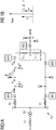
- FIG. 1a shows by way of example and schematically a power distribution network EV without decentralized power supply.
- This power distribution network EV consists of a local power transformer TR with a medium voltage side transformer fuse F5 and a busbar with branch fuses F1 and F3.
- the power distribution network EV has exemplary network sections ac, bc, cd (or distribution network lines) to which individual network subscribers V1 to V8 or consumers V1 to V8 are connected.
- These consumers V1 to V8 are in FIG. 1a shown as rectangular connection points for the respective network users or consumers V1 to V8.
- the consumers V1 and V2 are connected in the network section bc with the network separation points b and c.
- three consumers V5, V6, V7 are connected to the power distribution network EV.
- the Network section cd connected by means of a shorting bridge F2 or with the fuse F2 to the network section bc.
- the network section cd can also be connected to the network section ac by means of the short-circuiting bridge F4 or fuse F4 shown by dashed lines.
- this point can also be designed as a separation point F4, whereby there is no connection between the network sections cd and ac.
- the network section cd further consumers V3, V4, V8 are connected to the power distribution network EV.
- the respective network sections ac, bc, cd further devices MD1 to MD5 are provided, which serve a current measurement value detection in the respective network sections ac, bc, cd.
- the devices MD1 to MD5 for detecting current readings in the respective network sections ac, bc, cd are e.g. near or at the respective network section separating points a, b, c and d attached.
- a corresponding current balance of the network section bc is exemplary in FIG. 1b shown. From this it can be seen that the current I1 flowing into the network section bc is equal in magnitude to an amount of the sum of the currents 14, 15, 16 and 17 flowing out of the network section bc. With a correspondingly favorable network load situation in the considered network section bc, a current load limit value Imax for the network section bc is not exceeded by the current I1, which flows into the network section bc.
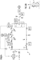
- FIG. 2a again schematically shows the exemplary power distribution network EV, which now has a decentralized power supply in the network sections bc, cd, and in which therefore the inventive system for monitoring and controlling a power distribution or the inventive method for monitoring and controlling the power distribution is used
- a power generation device DG1 eg photovoltaic system, etc.
- AD1 the inventive method for monitoring and controlling the power distribution
- a device MD6 for detecting current measured values is also provided.
- at least three devices MD3, MD4, MD6 are provided for detecting current measured values in the network section bc.
- the network section bc now has at least three devices MD3, MD4 and MD6 for detecting current measured values for measuring current measured values I1, 14, 16 has at least one decentralized power feed point e and at least two network section separating points b, c of the network section bc.
- the power distribution network EV also in the network section cd a second power generating device DG2 with associated control unit AD2, through which at the network section separation point d power or energy is fed into the network section cd.
- the network section separation point d thus becomes the decentralized power supply point d at which a device MD7 for detecting current measured values is mounted.
- a central monitoring unit CD belonging to the system according to the invention is provided in the exemplary illustrated energy supply network EV.
- This central monitoring unit CD has a control interface via which a communication device can be connected.
- the central monitoring unit CD on the one hand via the control interface and the associated communication device receive current readings measured by devices MD1 through MD7 for sensing current readings.
- control commands to the network users V1 to V5, V7, DG1, DG2 are sent by the central monitoring unit CD via the control interface and the associated communication device at least by means of unidirectional transmission.
- control commands are then processed in the respective control units AD1, AD2 of the power generating devices DG1, DG2, for example, to reduce or increase power generation, and received and evaluated by network load control devices in the power distribution network EV, corresponding to a network load in the respective network section ac, bc to fix cd.
- the devices MD1 to MD7 each have a communication device.
- the current measured values detected by the respective device MD1 to MD7 are sent to the central monitoring unit CD via at least one unidirectional transmission.
- the power distribution network EV itself can be used.
- a separate communication system such as. Radio communication or a combination of radio communication and power distribution network EV for the transmission of current readings and control commands are used.
- Devices MD1 to MD7, which are attached to the central monitoring unit CD, for example, can also be directly connected to this for communication.
- the network section bc in this case has the power generating device DG1, through which a current 16 or energy is fed into the network section bc via the decentralized power feed point e.
- a first method step 1 at least three devices MD3, MD4, MD6 are mounted in the network section bc for detecting current measured values. Then, in a second method step 2, measured current values at at least one decentralized current feed point e and at at least two network separation points b, c of the network section bc are measured. These are those locations in the network section bc at which potentially, e.g. Depending on the generation of energy or network load, electricity can flow into the network section bc.
- the detected current measured values I1, 14, 16 are transmitted from the devices MD3, MD4, MD6 for detecting current measured values - eg via the associated communication devices by means of at least unidirectional transmission - to the central monitoring unit CD.
- the transmitted current measured values I1, 14, 16 for the network section bc are evaluated by the central monitoring unit CD.
- a summation value of the detected current measured values I1, 14, 16 is formed for those current measured values or for those currents I1, 16 which flow into the network section bc.
- FIG. 2b an exemplary current balance for the network section bc belonging to method step 4 is shown.
- the currents I1, 16 flowing into the network section bc are juxtaposed with the currents 14, 15, 17 flowing out of the network section bc.
- FIG. 2b it can be seen that although the magnitude of the sum of the currents I1, 16 flowing into the network section bc is higher than the current I1, the current load limit Imax for the network section bc is not or not yet reached.
- a fifth method step 5 based on this comparison result that the current load limit value Imax is undershot, corresponding control commands from the central monitoring unit CD-e.g. via the associated control interface and the connected communication device - by means of at least unidirectional transmission e.g. transmitted via the power distribution network EV and / or radio communication to the network subscribers V5, V7, DG1 of the network section bc.
- a control command for example, the power generating device DG1 of the network section bc or the associated control unit AD1 a permission to increase the power generation / feed can be sent. It can also other network subscribers V5, V7 such.
- Energy storage unit or a network load control device are communicated by means of a control command that an increase in the network load in the network section bc is possible.
- the exemplary energy distribution network EV with decentralized energy supply in the network sections bc, cd is shown schematically, wherein also the system according to the invention for monitoring and controlling a power distribution is used.
- the exemplary network section bc is considered.
- the second stream 14 of the network section bc flows from the network section cd via the network section separation point c into the network section bc. If the entire available power or the total available energy is not needed or consumed in the network section bc as well, the first current I1 of the network section bc flows in the direction of the busbar or of the local network transformer TR.
- the current measured values are also measured at at least one decentralized current feed point e and at at least two network separation points b, c of the network section bc, ie at those points in the network section bc at which potentials e.g. Depending on the generation of energy or network load, electricity can flow into the network section bc. That is, in the second method step 2, the values of the currents I1, 14, 16 are detected by the corresponding devices MD3, MD4, MD6 for detecting current measured values.
- the detected current measured values I1, 14, 16 are then transmitted in the third method step 3 to the central monitoring unit CD and evaluated by the latter in the fourth method step 4 for the network section bc or a sum value for the now flowing into the network section bc streams 14, 16 and formed is compared with the current load limit Imax for the grid section bc.
- FIG. 3b By changing the direction of the first and third currents I1 and 14 in the network section bc now results in a FIG. 3b exemplified, changed power balance. It will be in FIG. 3b again the flows 14, 16 flowing into the network section bc are juxtaposed with the currents I1, 15, 17 flowing out of the network section bc. Since the first current I1 and third current 14 of the network section bc have changed direction due to the new current constellation, the first current I1 is now a current flowing out of the network section bc and becomes current with the currents 15, 17 V5, V7 flow, summed. The third stream 14 now flows into the network section bc, as does the second stream 16 from the power generation device DG1 of the network section bc.
- the second and third streams 14, 16 are now summed up. Furthermore, it can also be seen that the magnitude of the currents 14, 16 flowing into the network section bc is now greater than the current load limit value Imax for the network section bc. Therefore, for example, it could lead to an overload of the network section bc or to trigger the branch fuse F3 of the network section bc.
- corresponding control commands are transmitted from the central monitoring unit CD to the network subscribers V5, V7, DG1 of the network section bc.
- a control command for reducing the power generation / supply is sent from the decentralized monitoring unit CD to the power generating device DG1 or to the associated control unit AD1.
- a control command for throttling the power generation / feed to the second power generating device DG2 in the network section cd or the corresponding associated second control unit AD2 can be transmitted.
- both the in FIG. 2a as well as at the FIG. 3a Stream constellation receiving a control commands of the central monitoring unit CD in the power generating devices DG1, DG2 or in the associated control units AD1, AD2 and / or monitored in network load control devices.
- a reception quality of the control commands can be monitored.
- the network subscribers V1 to V7, DG1, DG2 - but above all the power generation devices DG1, DG2 and / or existing network load control devices - are placed in a safe operating mode.
- this safe mode of operation for example, power generation and / or network load are greatly reduced or kept to a minimum.
Claims (11)
- Procédé de surveillance et de commande d'une distribution de courant avec alimentation en énergie décentralisée dans un réseau de distribution d'énergie (EV) comprenant des dispositifs générateurs d'énergie (V1 à V7) et des consommateurs (V1 à V7) en tant qu'abonnés du réseau (V1 à V8, DG1, DG2), le réseau de distribution d'énergie (EV) étant constitué de plusieurs segments de réseau (ac, bc, cd) par l'intermédiaire desquels les abonnés du réseau (V1 à V7, DG1, DG2) sont raccordés au réseau de distribution d'énergie (EV), caractérisé en ce que dans un segment de réseau (ac, bc, cd) comprenant au moins un dispositif générateur d'énergie (DG1, DG2), au moins trois dispositifs destinés à détecter des valeurs de mesure de courant (MD1 à MD7) sont installés (1), en ce que des valeurs de mesure de courant (I1 à 17) sont détectées (2) par ces dispositifs destinés à détecter des valeurs de mesure de courant (MD1 à MD7) à au moins un point décentralisé d'alimentation en courant (d, e) et à au moins deux points de coupure de segment de réseau (a, b, c) du segment de réseau respectif (ac, bc, cd), en ce que les valeurs de mesure de courant (I1 à 17) détectées sont transmises (3) à une unité de surveillance centrale (CD), en ce qu'ensuite les valeurs de mesure de courant (I1 à 17) détectées sont évaluées par l'unité de surveillance centrale (CD) pour le segment de réseau respectif (ac, bc, cd), et en ce qu'ensuite une valeur totalisée pour les courants, lesquels entrent dans le segment de réseau respectif, est formée (4), en ce qu'ensuite la valeur totalisée des courants entrant dans le segment de réseau respectif (ac, bc, cd) est comparée (4) à une valeur limite de charge de courant (Imax) pour le segment de réseau respectif (ac, bc, cd), et en ce qu'ensuite des instructions de commande sont émises (5) par l'unité de surveillance centrale (CD) aux abonnés du réseau (V1 à V7, DG1, DG2) du segment de réseau respectif (ac, bc, cd) en fonction d'un résultat comparatif.
- Procédé selon la revendication 1, caractérisé en ce que lors d'un dépassement vers le haut de la valeur limite de charge de courant (Imax), des instructions de commande destinées à réduire une production de courant et/ou une charge du réseau sont émises (5) dans le segment de réseau respectif (ac, bc, cd) par l'unité de surveillance centrale (CD) aux abonnés du réseau respectifs (V1 à V7, DG1, DG2), notamment aux dispositifs générateur d'énergie (DG1, DG2) et/ou aux dispositif de commande de charge de réseau.
- Procédé selon la revendication 1, caractérisé en ce que lors d'un dépassement vers le bas de la valeur limite de charge de courant (Imax), des instructions de commande comprenant une autorisation d'augmenter la production de courant et/ou la charge du réseau sont émises (5) dans le segment de réseau respectif (ac, bc, cd) par l'unité de surveillance centrale (CD) aux abonnés du réseau respectifs (V1 à V7, DG1, DG2), notamment aux dispositifs générateur d'énergie (DG1, DG2) et/ou aux dispositif de commande de charge de réseau.
- Procédé selon l'une quelconque des revendications 1 à 3, caractérisé en ce que les valeurs de mesure de courant détectées (I1 à 17) des dispositifs (MD1 à MD7) destinés à détecter des valeurs de mesure de courant et les instructions de commande de l'unité de surveillance centrale (CD) sont transmises (3, 5) au moins au moyen de transmission de données unidirectionnelle.
- Procédé selon l'une quelconque des revendications 1 à 4, caractérisé en ce qu'une réception d'instructions de commande dans les dispositifs générateurs d'énergie respectifs (DG1, DDG2) et/ou dans les dispositifs de commande de charge de réseau est surveillée (5).
- Procédé selon l'une quelconque des revendications 1 à 5, caractérisé en ce que lors de la constatation d'une qualité de réception moindre ou de l'absence de la réception d'instructions de commande du dispositif de surveillance central (CD) pendant une période de temps d'observation prédéfinie, les abonnés du réseau (V1 à V7, DG1, DG2), notamment les dispositifs générateurs d'énergie (DG1, DG2) et les dispositifs de commande de charge de réseau, passent (5) dans un mode de fonctionnement sûr.
- Procédé selon l'une quelconque des revendications 1 à 6, caractérisé en ce que pour une transmission des valeurs de mesure de courant (I1 à 17) détectées et des instructions de commande, le réseau de distribution d'énergie (EV) est utilisé comme moyen de communication.
- Système destiné à la réalisation d'un procédé selon l'une quelconque des revendications précédentes 1 à 7, destiné à la surveillance et à la commande d'une distribution de courant avec alimentation en énergie décentralisée dans un réseau de distribution d'énergie (EV) constitué au moins d' :- au moins trois dispositifs (MD1 à MD7) destinés à détecter des valeurs de mesure de courant par segment de réseau (ac, bc, cd), au moyen desquels des mesures de courant peuvent être effectuées à au moins un point décentralisé d'alimentation en courant (d, e) et à au moins deux points de coupure du réseau (a, b, c) du segment de réseau respectif (ac, bc, cd),- et d'une unité de surveillance centrale (CD) destinée à recevoir et évaluer des valeurs de mesure de courant détectées (I1 à 17), à former une valeur totalisée pour des courants entrant dans le segment de réseau respectif et à émettre des instructions de commande aux abonnés du réseau (V1 à V7, DG 1, DG2) pour une commande d'une production de courant et/ou d'une charge de réseau dans les segments de réseau respectifs (ac, bc, cd) du réseau de distribution d'énergie (EV).
- Système selon la revendication 8, caractérisé en ce que les au moins trois dispositifs destinés à détecter des valeurs de mesure de courant par segment de réseau présentent respectivement un dispositif de communication, lequel peut être utilisé pour au moins une transmission unidirectionnelle à l'unité de surveillance centrale de valeurs de courant détectées.
- Système selon l'une quelconque des revendications 8 à 9, caractérisé en ce que l'unité de surveillance centrale (CD) présente une interface de commande, laquelle est reliée à un dispositif de communication qui peut être utilisé pour une réception de valeurs de mesure de courant (I1 à 17) détectées par les dispositifs (MD1 à MD7) destinés à détecter des valeurs de mesure de courant ainsi que pour une émission d'instructions de commande aux abonnés du réseau (V1 à V7, DG1, DG2), notamment aux dispositifs générateurs d'énergie (DG1, DG2) et/ou aux dispositifs de commande de charge du réseau.
- Système selon l'une quelconque des revendications 9 à 10, caractérisé en ce que pour les dispositifs de communication des dispositifs (MD1 à MD7) destinés à détecter des valeurs de mesure de courant et pour le dispositif de communication de l'unité de surveillance centrale (CD), le réseau de distribution d'énergie (EV) est exploitable comme moyen de communication.
Priority Applications (1)
| Application Number | Priority Date | Filing Date | Title |
|---|---|---|---|
| EP13192631.3A EP2874265B1 (fr) | 2013-11-13 | 2013-11-13 | Procédé et système de surveillance et de commande d'une distribution de courant dans un réseau de distribution d'énergie |
Applications Claiming Priority (1)
| Application Number | Priority Date | Filing Date | Title |
|---|---|---|---|
| EP13192631.3A EP2874265B1 (fr) | 2013-11-13 | 2013-11-13 | Procédé et système de surveillance et de commande d'une distribution de courant dans un réseau de distribution d'énergie |
Publications (2)
| Publication Number | Publication Date |
|---|---|
| EP2874265A1 EP2874265A1 (fr) | 2015-05-20 |
| EP2874265B1 true EP2874265B1 (fr) | 2017-07-19 |
Family
ID=49639715
Family Applications (1)
| Application Number | Title | Priority Date | Filing Date |
|---|---|---|---|
| EP13192631.3A Active EP2874265B1 (fr) | 2013-11-13 | 2013-11-13 | Procédé et système de surveillance et de commande d'une distribution de courant dans un réseau de distribution d'énergie |
Country Status (1)
| Country | Link |
|---|---|
| EP (1) | EP2874265B1 (fr) |
Cited By (1)
| Publication number | Priority date | Publication date | Assignee | Title |
|---|---|---|---|---|
| CN111541306A (zh) * | 2020-05-14 | 2020-08-14 | 国网内蒙古东部电力有限公司电力科学研究院 | 一种微电网电力装置 |
Families Citing this family (2)
| Publication number | Priority date | Publication date | Assignee | Title |
|---|---|---|---|---|
| JP6718607B2 (ja) * | 2015-07-29 | 2020-07-08 | 京セラ株式会社 | 管理サーバ及び管理方法 |
| DE102017006619A1 (de) | 2017-07-12 | 2019-01-17 | Stiebel Eltron Gmbh & Co. Kg | Verfahren zum Betrieb von Haustechnikanlagen in einem elektrischen Stromnetz |
Family Cites Families (7)
| Publication number | Priority date | Publication date | Assignee | Title |
|---|---|---|---|---|
| US6219591B1 (en) * | 1998-05-15 | 2001-04-17 | Abb Power T&D Company Inc. | Voltage instability predictor (VIP)—method and system for performing adaptive control to improve voltage stability in power systems |
| DE102005056084A1 (de) * | 2005-11-24 | 2007-06-14 | Dehn + Söhne Gmbh + Co. Kg | Verfahren zur Kontrolle und zur Steuerung bereitzustellender elektrischer Energie sowie zur Harmonisierung der Belastungsstrukur eines Versorgungsnetzes |
| US7603203B2 (en) * | 2006-10-09 | 2009-10-13 | Electric Power Research Institute, Inc. | Method for voltage instability load shedding using local measurements |
| WO2009106129A1 (fr) * | 2008-02-26 | 2009-09-03 | Siemens Aktiengesellschaft | Procédé et dispositif destinés à la détermination d'une qualité de signal et système comportant un dispositif de ce type |
| EP2697887A2 (fr) * | 2011-04-15 | 2014-02-19 | Siemens Aktiengesellschaft | Procédé et dispositif de mesure de courant pour identifier des prélèvements de courant ou des arrivées de courant dans un réseau de distribution basse tension électrique |
| WO2012139657A2 (fr) * | 2011-04-15 | 2012-10-18 | Siemens Aktiengesellschaft | Réseau de distribution d'énergie et son procédé de fonctionnement |
| US9088180B2 (en) * | 2012-04-17 | 2015-07-21 | Generac Power Systems, Inc. | Load shed control module for use with electrical generator |
-
2013
- 2013-11-13 EP EP13192631.3A patent/EP2874265B1/fr active Active
Cited By (1)
| Publication number | Priority date | Publication date | Assignee | Title |
|---|---|---|---|---|
| CN111541306A (zh) * | 2020-05-14 | 2020-08-14 | 国网内蒙古东部电力有限公司电力科学研究院 | 一种微电网电力装置 |
Also Published As
| Publication number | Publication date |
|---|---|
| EP2874265A1 (fr) | 2015-05-20 |
Similar Documents
| Publication | Publication Date | Title |
|---|---|---|
| EP2697888B1 (fr) | Méthode de détermination de la topologie d'un réseau de distribution basse tension | |
| EP3645865B9 (fr) | Système éolien et procédé de régulation d'une installation éolienne | |
| WO2013013656A2 (fr) | Procédé de régulation adaptative de la tension d'alimentation dans des réseaux locaux | |
| EP3042428A1 (fr) | Dispositif et procédé permettant de commander la stabilité d'un réseau régional pourvu d'un transformateur de réseau régional réglable | |
| DE112013007265T5 (de) | System zur Solarenergiegewinnung, Messeinheit und Positionierungsverfahren | |
| EP2874265B1 (fr) | Procédé et système de surveillance et de commande d'une distribution de courant dans un réseau de distribution d'énergie | |
| DE102014115119A1 (de) | Verfahren und System zum Überwachen einer Netzspannung in einem Niederspannungsnetz | |
| EP2978091B1 (fr) | Procédé de transmission d'énergie électrique | |
| WO2012139656A1 (fr) | Réseau de distribution d'énergie et procédé d'exploitation de ce réseau | |
| DE102017101413A1 (de) | Verfahren zur Einsatzplanung eines elektrischen Systems zur Energieversorgung | |
| DE102012220846B3 (de) | Verfahren zur Topologieerkennung in einem Niederspannungsnetz | |
| EP2930813B1 (fr) | Procédé et dispositif d'enregistrement d'une grandeur électrique d'un réseau de distribution électrique | |
| EP3751699A1 (fr) | Procédé et dispositif d'estimation d'un état d'un réseau de distribution d'énergie | |
| EP3216106B1 (fr) | Procédé d'enrichissement d'enregistrements de mesure d'un réseau basse tension | |
| DE102010023112A1 (de) | Energieübertragungseinrichtung | |
| EP3413422A1 (fr) | Station de réseau local pourvue de sorties basse tension variables | |
| WO2013104423A1 (fr) | Réseau de distribution d'énergie | |
| WO2019030048A1 (fr) | Dispositif de stockage d'énergie électrique | |
| EP3916944A1 (fr) | Procédé de fonctionnement d'un système d'alimentation énergétique et système d'alimentation énergétique | |
| EP2993548B1 (fr) | Réglage d'une alimentation en tension | |
| DE102009060527A1 (de) | Verfahren zur Leistungsregelung innerhalb eines Netzwerksegments eines Wechselspannungsnetzwerkes und Netzwerksegment | |
| EP3490093A1 (fr) | Réseaux et procédés d'alimentation en énergie | |
| DE102010021070A1 (de) | Verfahren zur Regelung der Stabilität eines elektrichen Versorgungsnetzwerks | |
| EP3510683B1 (fr) | Procédé et système de régulation décentralisée longue portée | |
| DE102016218352A1 (de) | Bewerten einer elektrischen Belastbarkeit eines elektrischen Energieverteilungsnetzes |
Legal Events
| Date | Code | Title | Description |
|---|---|---|---|
| PUAI | Public reference made under article 153(3) epc to a published international application that has entered the european phase |
Free format text: ORIGINAL CODE: 0009012 |
|
| 17P | Request for examination filed |
Effective date: 20131113 |
|
| AK | Designated contracting states |
Kind code of ref document: A1 Designated state(s): AL AT BE BG CH CY CZ DE DK EE ES FI FR GB GR HR HU IE IS IT LI LT LU LV MC MK MT NL NO PL PT RO RS SE SI SK SM TR |
|
| AX | Request for extension of the european patent |
Extension state: BA ME |
|
| R17P | Request for examination filed (corrected) |
Effective date: 20151117 |
|
| RBV | Designated contracting states (corrected) |
Designated state(s): AL AT BE BG CH CY CZ DE DK EE ES FI FR GB GR HR HU IE IS IT LI LT LU LV MC MK MT NL NO PL PT RO RS SE SI SK SM TR |
|
| 17Q | First examination report despatched |
Effective date: 20160127 |
|
| GRAP | Despatch of communication of intention to grant a patent |
Free format text: ORIGINAL CODE: EPIDOSNIGR1 |
|
| STAA | Information on the status of an ep patent application or granted ep patent |
Free format text: STATUS: GRANT OF PATENT IS INTENDED |
|
| INTG | Intention to grant announced |
Effective date: 20170217 |
|
| RIN1 | Information on inventor provided before grant (corrected) |
Inventor name: SCHENK, ALEXANDER Inventor name: KUSSYK, JAROSLAW |
|
| GRAS | Grant fee paid |
Free format text: ORIGINAL CODE: EPIDOSNIGR3 |
|
| GRAA | (expected) grant |
Free format text: ORIGINAL CODE: 0009210 |
|
| STAA | Information on the status of an ep patent application or granted ep patent |
Free format text: STATUS: THE PATENT HAS BEEN GRANTED |
|
| AK | Designated contracting states |
Kind code of ref document: B1 Designated state(s): AL AT BE BG CH CY CZ DE DK EE ES FI FR GB GR HR HU IE IS IT LI LT LU LV MC MK MT NL NO PL PT RO RS SE SI SK SM TR |
|
| REG | Reference to a national code |
Ref country code: GB Ref legal event code: FG4D Free format text: NOT ENGLISH |
|
| REG | Reference to a national code |
Ref country code: CH Ref legal event code: EP |
|
| REG | Reference to a national code |
Ref country code: IE Ref legal event code: FG4D Free format text: LANGUAGE OF EP DOCUMENT: GERMAN |
|
| REG | Reference to a national code |
Ref country code: AT Ref legal event code: REF Ref document number: 911263 Country of ref document: AT Kind code of ref document: T Effective date: 20170815 |
|
| RAP2 | Party data changed (patent owner data changed or rights of a patent transferred) |
Owner name: SIEMENS AKTIENGESELLSCHAFT |
|
| REG | Reference to a national code |
Ref country code: DE Ref legal event code: R096 Ref document number: 502013007795 Country of ref document: DE |
|
| REG | Reference to a national code |
Ref country code: CH Ref legal event code: NV Representative=s name: SIEMENS SCHWEIZ AG, CH Ref country code: CH Ref legal event code: PCOW Free format text: NEW ADDRESS: WERNER-VON-SIEMENS-STRASSE 1, 80333 MUENCHEN (DE) |
|
| REG | Reference to a national code |
Ref country code: FR Ref legal event code: PLFP Year of fee payment: 5 |
|
| REG | Reference to a national code |
Ref country code: NL Ref legal event code: MP Effective date: 20170719 |
|
| REG | Reference to a national code |
Ref country code: LT Ref legal event code: MG4D |
|
| PG25 | Lapsed in a contracting state [announced via postgrant information from national office to epo] |
Ref country code: FI Free format text: LAPSE BECAUSE OF FAILURE TO SUBMIT A TRANSLATION OF THE DESCRIPTION OR TO PAY THE FEE WITHIN THE PRESCRIBED TIME-LIMIT Effective date: 20170719 Ref country code: SE Free format text: LAPSE BECAUSE OF FAILURE TO SUBMIT A TRANSLATION OF THE DESCRIPTION OR TO PAY THE FEE WITHIN THE PRESCRIBED TIME-LIMIT Effective date: 20170719 Ref country code: NL Free format text: LAPSE BECAUSE OF FAILURE TO SUBMIT A TRANSLATION OF THE DESCRIPTION OR TO PAY THE FEE WITHIN THE PRESCRIBED TIME-LIMIT Effective date: 20170719 Ref country code: NO Free format text: LAPSE BECAUSE OF FAILURE TO SUBMIT A TRANSLATION OF THE DESCRIPTION OR TO PAY THE FEE WITHIN THE PRESCRIBED TIME-LIMIT Effective date: 20171019 Ref country code: LT Free format text: LAPSE BECAUSE OF FAILURE TO SUBMIT A TRANSLATION OF THE DESCRIPTION OR TO PAY THE FEE WITHIN THE PRESCRIBED TIME-LIMIT Effective date: 20170719 Ref country code: HR Free format text: LAPSE BECAUSE OF FAILURE TO SUBMIT A TRANSLATION OF THE DESCRIPTION OR TO PAY THE FEE WITHIN THE PRESCRIBED TIME-LIMIT Effective date: 20170719 |
|
| PG25 | Lapsed in a contracting state [announced via postgrant information from national office to epo] |
Ref country code: ES Free format text: LAPSE BECAUSE OF FAILURE TO SUBMIT A TRANSLATION OF THE DESCRIPTION OR TO PAY THE FEE WITHIN THE PRESCRIBED TIME-LIMIT Effective date: 20170719 Ref country code: LV Free format text: LAPSE BECAUSE OF FAILURE TO SUBMIT A TRANSLATION OF THE DESCRIPTION OR TO PAY THE FEE WITHIN THE PRESCRIBED TIME-LIMIT Effective date: 20170719 Ref country code: GR Free format text: LAPSE BECAUSE OF FAILURE TO SUBMIT A TRANSLATION OF THE DESCRIPTION OR TO PAY THE FEE WITHIN THE PRESCRIBED TIME-LIMIT Effective date: 20171020 Ref country code: RS Free format text: LAPSE BECAUSE OF FAILURE TO SUBMIT A TRANSLATION OF THE DESCRIPTION OR TO PAY THE FEE WITHIN THE PRESCRIBED TIME-LIMIT Effective date: 20170719 Ref country code: IS Free format text: LAPSE BECAUSE OF FAILURE TO SUBMIT A TRANSLATION OF THE DESCRIPTION OR TO PAY THE FEE WITHIN THE PRESCRIBED TIME-LIMIT Effective date: 20171119 Ref country code: BG Free format text: LAPSE BECAUSE OF FAILURE TO SUBMIT A TRANSLATION OF THE DESCRIPTION OR TO PAY THE FEE WITHIN THE PRESCRIBED TIME-LIMIT Effective date: 20171019 Ref country code: PL Free format text: LAPSE BECAUSE OF FAILURE TO SUBMIT A TRANSLATION OF THE DESCRIPTION OR TO PAY THE FEE WITHIN THE PRESCRIBED TIME-LIMIT Effective date: 20170719 |
|
| REG | Reference to a national code |
Ref country code: DE Ref legal event code: R097 Ref document number: 502013007795 Country of ref document: DE |
|
| PG25 | Lapsed in a contracting state [announced via postgrant information from national office to epo] |
Ref country code: RO Free format text: LAPSE BECAUSE OF FAILURE TO SUBMIT A TRANSLATION OF THE DESCRIPTION OR TO PAY THE FEE WITHIN THE PRESCRIBED TIME-LIMIT Effective date: 20170719 Ref country code: DK Free format text: LAPSE BECAUSE OF FAILURE TO SUBMIT A TRANSLATION OF THE DESCRIPTION OR TO PAY THE FEE WITHIN THE PRESCRIBED TIME-LIMIT Effective date: 20170719 Ref country code: CZ Free format text: LAPSE BECAUSE OF FAILURE TO SUBMIT A TRANSLATION OF THE DESCRIPTION OR TO PAY THE FEE WITHIN THE PRESCRIBED TIME-LIMIT Effective date: 20170719 |
|
| PLBE | No opposition filed within time limit |
Free format text: ORIGINAL CODE: 0009261 |
|
| STAA | Information on the status of an ep patent application or granted ep patent |
Free format text: STATUS: NO OPPOSITION FILED WITHIN TIME LIMIT |
|
| PG25 | Lapsed in a contracting state [announced via postgrant information from national office to epo] |
Ref country code: EE Free format text: LAPSE BECAUSE OF FAILURE TO SUBMIT A TRANSLATION OF THE DESCRIPTION OR TO PAY THE FEE WITHIN THE PRESCRIBED TIME-LIMIT Effective date: 20170719 Ref country code: IT Free format text: LAPSE BECAUSE OF FAILURE TO SUBMIT A TRANSLATION OF THE DESCRIPTION OR TO PAY THE FEE WITHIN THE PRESCRIBED TIME-LIMIT Effective date: 20170719 Ref country code: SM Free format text: LAPSE BECAUSE OF FAILURE TO SUBMIT A TRANSLATION OF THE DESCRIPTION OR TO PAY THE FEE WITHIN THE PRESCRIBED TIME-LIMIT Effective date: 20170719 Ref country code: SK Free format text: LAPSE BECAUSE OF FAILURE TO SUBMIT A TRANSLATION OF THE DESCRIPTION OR TO PAY THE FEE WITHIN THE PRESCRIBED TIME-LIMIT Effective date: 20170719 |
|
| 26N | No opposition filed |
Effective date: 20180420 |
|
| PG25 | Lapsed in a contracting state [announced via postgrant information from national office to epo] |
Ref country code: MC Free format text: LAPSE BECAUSE OF FAILURE TO SUBMIT A TRANSLATION OF THE DESCRIPTION OR TO PAY THE FEE WITHIN THE PRESCRIBED TIME-LIMIT Effective date: 20170719 |
|
| PG25 | Lapsed in a contracting state [announced via postgrant information from national office to epo] |
Ref country code: CH Free format text: LAPSE BECAUSE OF NON-PAYMENT OF DUE FEES Effective date: 20171130 Ref country code: LI Free format text: LAPSE BECAUSE OF NON-PAYMENT OF DUE FEES Effective date: 20171130 |
|
| PG25 | Lapsed in a contracting state [announced via postgrant information from national office to epo] |
Ref country code: LU Free format text: LAPSE BECAUSE OF NON-PAYMENT OF DUE FEES Effective date: 20171113 Ref country code: SI Free format text: LAPSE BECAUSE OF FAILURE TO SUBMIT A TRANSLATION OF THE DESCRIPTION OR TO PAY THE FEE WITHIN THE PRESCRIBED TIME-LIMIT Effective date: 20170719 |
|
| REG | Reference to a national code |
Ref country code: BE Ref legal event code: MM Effective date: 20171130 |
|
| REG | Reference to a national code |
Ref country code: IE Ref legal event code: MM4A |
|
| PG25 | Lapsed in a contracting state [announced via postgrant information from national office to epo] |
Ref country code: MT Free format text: LAPSE BECAUSE OF FAILURE TO SUBMIT A TRANSLATION OF THE DESCRIPTION OR TO PAY THE FEE WITHIN THE PRESCRIBED TIME-LIMIT Effective date: 20170719 |
|
| PG25 | Lapsed in a contracting state [announced via postgrant information from national office to epo] |
Ref country code: IE Free format text: LAPSE BECAUSE OF NON-PAYMENT OF DUE FEES Effective date: 20171113 |
|
| PG25 | Lapsed in a contracting state [announced via postgrant information from national office to epo] |
Ref country code: BE Free format text: LAPSE BECAUSE OF NON-PAYMENT OF DUE FEES Effective date: 20171130 |
|
| PG25 | Lapsed in a contracting state [announced via postgrant information from national office to epo] |
Ref country code: HU Free format text: LAPSE BECAUSE OF FAILURE TO SUBMIT A TRANSLATION OF THE DESCRIPTION OR TO PAY THE FEE WITHIN THE PRESCRIBED TIME-LIMIT; INVALID AB INITIO Effective date: 20131113 |
|
| PG25 | Lapsed in a contracting state [announced via postgrant information from national office to epo] |
Ref country code: CY Free format text: LAPSE BECAUSE OF FAILURE TO SUBMIT A TRANSLATION OF THE DESCRIPTION OR TO PAY THE FEE WITHIN THE PRESCRIBED TIME-LIMIT Effective date: 20170719 |
|
| PG25 | Lapsed in a contracting state [announced via postgrant information from national office to epo] |
Ref country code: MK Free format text: LAPSE BECAUSE OF FAILURE TO SUBMIT A TRANSLATION OF THE DESCRIPTION OR TO PAY THE FEE WITHIN THE PRESCRIBED TIME-LIMIT Effective date: 20170719 |
|
| PG25 | Lapsed in a contracting state [announced via postgrant information from national office to epo] |
Ref country code: TR Free format text: LAPSE BECAUSE OF FAILURE TO SUBMIT A TRANSLATION OF THE DESCRIPTION OR TO PAY THE FEE WITHIN THE PRESCRIBED TIME-LIMIT Effective date: 20170719 |
|
| PG25 | Lapsed in a contracting state [announced via postgrant information from national office to epo] |
Ref country code: PT Free format text: LAPSE BECAUSE OF FAILURE TO SUBMIT A TRANSLATION OF THE DESCRIPTION OR TO PAY THE FEE WITHIN THE PRESCRIBED TIME-LIMIT Effective date: 20170719 |
|
| PG25 | Lapsed in a contracting state [announced via postgrant information from national office to epo] |
Ref country code: AL Free format text: LAPSE BECAUSE OF FAILURE TO SUBMIT A TRANSLATION OF THE DESCRIPTION OR TO PAY THE FEE WITHIN THE PRESCRIBED TIME-LIMIT Effective date: 20170719 |
|
| PGFP | Annual fee paid to national office [announced via postgrant information from national office to epo] |
Ref country code: DE Payment date: 20220620 Year of fee payment: 10 |
|
| PGFP | Annual fee paid to national office [announced via postgrant information from national office to epo] |
Ref country code: GB Payment date: 20231204 Year of fee payment: 11 |
|
| PGFP | Annual fee paid to national office [announced via postgrant information from national office to epo] |
Ref country code: FR Payment date: 20231114 Year of fee payment: 11 Ref country code: AT Payment date: 20231012 Year of fee payment: 11 |