EP2874219A1 - Membrane electrode assembly - Google Patents
Membrane electrode assembly Download PDFInfo
- Publication number
- EP2874219A1 EP2874219A1 EP13816315.9A EP13816315A EP2874219A1 EP 2874219 A1 EP2874219 A1 EP 2874219A1 EP 13816315 A EP13816315 A EP 13816315A EP 2874219 A1 EP2874219 A1 EP 2874219A1
- Authority
- EP
- European Patent Office
- Prior art keywords
- holes
- electrolyte membrane
- gasket
- polymer electrolyte
- electrode assembly
- Prior art date
- Legal status (The legal status is an assumption and is not a legal conclusion. Google has not performed a legal analysis and makes no representation as to the accuracy of the status listed.)
- Granted
Links
- 239000012528 membrane Substances 0.000 title claims abstract description 91
- 239000003792 electrolyte Substances 0.000 claims abstract description 27
- 230000002093 peripheral effect Effects 0.000 claims abstract description 26
- 239000003054 catalyst Substances 0.000 abstract description 57
- 239000007789 gas Substances 0.000 abstract description 32
- 239000002737 fuel gas Substances 0.000 abstract description 13
- 239000007800 oxidant agent Substances 0.000 abstract description 13
- 230000001590 oxidative effect Effects 0.000 abstract description 7
- 239000005518 polymer electrolyte Substances 0.000 description 50
- OKKJLVBELUTLKV-UHFFFAOYSA-N Methanol Chemical compound OC OKKJLVBELUTLKV-UHFFFAOYSA-N 0.000 description 12
- 238000009792 diffusion process Methods 0.000 description 12
- 239000000446 fuel Substances 0.000 description 12
- OKTJSMMVPCPJKN-UHFFFAOYSA-N Carbon Chemical group [C] OKTJSMMVPCPJKN-UHFFFAOYSA-N 0.000 description 9
- 239000000463 material Substances 0.000 description 7
- YCKRFDGAMUMZLT-UHFFFAOYSA-N Fluorine atom Chemical compound [F] YCKRFDGAMUMZLT-UHFFFAOYSA-N 0.000 description 6
- 229910052799 carbon Inorganic materials 0.000 description 6
- 239000011737 fluorine Substances 0.000 description 6
- 229910052731 fluorine Inorganic materials 0.000 description 6
- -1 polytetrafluoroethylene Polymers 0.000 description 5
- UFHFLCQGNIYNRP-UHFFFAOYSA-N Hydrogen Chemical compound [H][H] UFHFLCQGNIYNRP-UHFFFAOYSA-N 0.000 description 4
- 239000002033 PVDF binder Substances 0.000 description 4
- 229920001971 elastomer Polymers 0.000 description 4
- 239000001257 hydrogen Substances 0.000 description 4
- 229910052739 hydrogen Inorganic materials 0.000 description 4
- 229910052751 metal Inorganic materials 0.000 description 4
- 239000002184 metal Substances 0.000 description 4
- BASFCYQUMIYNBI-UHFFFAOYSA-N platinum Chemical compound [Pt] BASFCYQUMIYNBI-UHFFFAOYSA-N 0.000 description 4
- 229920000642 polymer Polymers 0.000 description 4
- 229920001343 polytetrafluoroethylene Polymers 0.000 description 4
- 239000004810 polytetrafluoroethylene Substances 0.000 description 4
- 229920002981 polyvinylidene fluoride Polymers 0.000 description 4
- XLYOFNOQVPJJNP-UHFFFAOYSA-N water Substances O XLYOFNOQVPJJNP-UHFFFAOYSA-N 0.000 description 4
- RTZKZFJDLAIYFH-UHFFFAOYSA-N Diethyl ether Chemical compound CCOCC RTZKZFJDLAIYFH-UHFFFAOYSA-N 0.000 description 3
- LFQSCWFLJHTTHZ-UHFFFAOYSA-N Ethanol Chemical compound CCO LFQSCWFLJHTTHZ-UHFFFAOYSA-N 0.000 description 3
- LYCAIKOWRPUZTN-UHFFFAOYSA-N Ethylene glycol Chemical compound OCCO LYCAIKOWRPUZTN-UHFFFAOYSA-N 0.000 description 3
- KFZMGEQAYNKOFK-UHFFFAOYSA-N Isopropanol Chemical compound CC(C)O KFZMGEQAYNKOFK-UHFFFAOYSA-N 0.000 description 3
- 230000003197 catalytic effect Effects 0.000 description 3
- 239000002826 coolant Substances 0.000 description 3
- 238000001816 cooling Methods 0.000 description 3
- MTHSVFCYNBDYFN-UHFFFAOYSA-N diethylene glycol Chemical compound OCCOCCO MTHSVFCYNBDYFN-UHFFFAOYSA-N 0.000 description 3
- 230000000694 effects Effects 0.000 description 3
- 239000002861 polymer material Substances 0.000 description 3
- BDERNNFJNOPAEC-UHFFFAOYSA-N propan-1-ol Chemical compound CCCO BDERNNFJNOPAEC-UHFFFAOYSA-N 0.000 description 3
- 229920005989 resin Polymers 0.000 description 3
- 239000011347 resin Substances 0.000 description 3
- 239000010935 stainless steel Substances 0.000 description 3
- 229910001220 stainless steel Inorganic materials 0.000 description 3
- LSNNMFCWUKXFEE-UHFFFAOYSA-M Bisulfite Chemical compound OS([O-])=O LSNNMFCWUKXFEE-UHFFFAOYSA-M 0.000 description 2
- 239000004215 Carbon black (E152) Substances 0.000 description 2
- LCGLNKUTAGEVQW-UHFFFAOYSA-N Dimethyl ether Chemical compound COC LCGLNKUTAGEVQW-UHFFFAOYSA-N 0.000 description 2
- XEEYBQQBJWHFJM-UHFFFAOYSA-N Iron Chemical compound [Fe] XEEYBQQBJWHFJM-UHFFFAOYSA-N 0.000 description 2
- LRHPLDYGYMQRHN-UHFFFAOYSA-N N-Butanol Chemical compound CCCCO LRHPLDYGYMQRHN-UHFFFAOYSA-N 0.000 description 2
- PXHVJJICTQNCMI-UHFFFAOYSA-N Nickel Chemical compound [Ni] PXHVJJICTQNCMI-UHFFFAOYSA-N 0.000 description 2
- KDLHZDBZIXYQEI-UHFFFAOYSA-N Palladium Chemical compound [Pd] KDLHZDBZIXYQEI-UHFFFAOYSA-N 0.000 description 2
- NBIIXXVUZAFLBC-UHFFFAOYSA-N Phosphoric acid Chemical compound OP(O)(O)=O NBIIXXVUZAFLBC-UHFFFAOYSA-N 0.000 description 2
- 229910052782 aluminium Inorganic materials 0.000 description 2
- XAGFODPZIPBFFR-UHFFFAOYSA-N aluminium Chemical compound [Al] XAGFODPZIPBFFR-UHFFFAOYSA-N 0.000 description 2
- QVGXLLKOCUKJST-UHFFFAOYSA-N atomic oxygen Chemical compound [O] QVGXLLKOCUKJST-UHFFFAOYSA-N 0.000 description 2
- 230000004888 barrier function Effects 0.000 description 2
- 230000015572 biosynthetic process Effects 0.000 description 2
- 239000000969 carrier Substances 0.000 description 2
- 125000001153 fluoro group Chemical group F* 0.000 description 2
- 229930195733 hydrocarbon Natural products 0.000 description 2
- 150000002430 hydrocarbons Chemical class 0.000 description 2
- 230000004048 modification Effects 0.000 description 2
- 238000012986 modification Methods 0.000 description 2
- 230000003647 oxidation Effects 0.000 description 2
- 238000007254 oxidation reaction Methods 0.000 description 2
- 239000001301 oxygen Substances 0.000 description 2
- 229910052760 oxygen Inorganic materials 0.000 description 2
- 239000002245 particle Substances 0.000 description 2
- 229920009441 perflouroethylene propylene Polymers 0.000 description 2
- 229910052697 platinum Inorganic materials 0.000 description 2
- 229920000728 polyester Polymers 0.000 description 2
- 238000003825 pressing Methods 0.000 description 2
- 230000009467 reduction Effects 0.000 description 2
- 230000002940 repellent Effects 0.000 description 2
- 239000005871 repellent Substances 0.000 description 2
- TXEYQDLBPFQVAA-UHFFFAOYSA-N tetrafluoromethane Chemical compound FC(F)(F)F TXEYQDLBPFQVAA-UHFFFAOYSA-N 0.000 description 2
- 229920005992 thermoplastic resin Polymers 0.000 description 2
- 229920003934 Aciplex® Polymers 0.000 description 1
- UGFAIRIUMAVXCW-UHFFFAOYSA-N Carbon monoxide Chemical compound [O+]#[C-] UGFAIRIUMAVXCW-UHFFFAOYSA-N 0.000 description 1
- VYZAMTAEIAYCRO-UHFFFAOYSA-N Chromium Chemical compound [Cr] VYZAMTAEIAYCRO-UHFFFAOYSA-N 0.000 description 1
- 229920002943 EPDM rubber Polymers 0.000 description 1
- 229920000181 Ethylene propylene rubber Polymers 0.000 description 1
- 229920003935 Flemion® Polymers 0.000 description 1
- GYHNNYVSQQEPJS-UHFFFAOYSA-N Gallium Chemical compound [Ga] GYHNNYVSQQEPJS-UHFFFAOYSA-N 0.000 description 1
- ZOKXTWBITQBERF-UHFFFAOYSA-N Molybdenum Chemical compound [Mo] ZOKXTWBITQBERF-UHFFFAOYSA-N 0.000 description 1
- 229920000557 Nafion® Polymers 0.000 description 1
- 239000004698 Polyethylene Substances 0.000 description 1
- 229920002367 Polyisobutene Polymers 0.000 description 1
- 239000004743 Polypropylene Substances 0.000 description 1
- KJTLSVCANCCWHF-UHFFFAOYSA-N Ruthenium Chemical compound [Ru] KJTLSVCANCCWHF-UHFFFAOYSA-N 0.000 description 1
- DKGAVHZHDRPRBM-UHFFFAOYSA-N Tert-Butanol Chemical compound CC(C)(C)O DKGAVHZHDRPRBM-UHFFFAOYSA-N 0.000 description 1
- 230000009471 action Effects 0.000 description 1
- 229910045601 alloy Inorganic materials 0.000 description 1
- 239000000956 alloy Substances 0.000 description 1
- 229910000147 aluminium phosphate Inorganic materials 0.000 description 1
- 229910021383 artificial graphite Inorganic materials 0.000 description 1
- BTANRVKWQNVYAZ-UHFFFAOYSA-N butan-2-ol Chemical compound CCC(C)O BTANRVKWQNVYAZ-UHFFFAOYSA-N 0.000 description 1
- 239000006229 carbon black Substances 0.000 description 1
- 229910002091 carbon monoxide Inorganic materials 0.000 description 1
- 239000011248 coating agent Substances 0.000 description 1
- 238000000576 coating method Methods 0.000 description 1
- 229910017052 cobalt Inorganic materials 0.000 description 1
- 239000010941 cobalt Substances 0.000 description 1
- GUTLYIVDDKVIGB-UHFFFAOYSA-N cobalt atom Chemical compound [Co] GUTLYIVDDKVIGB-UHFFFAOYSA-N 0.000 description 1
- 239000000571 coke Substances 0.000 description 1
- 239000000470 constituent Substances 0.000 description 1
- 229920001577 copolymer Polymers 0.000 description 1
- 238000005260 corrosion Methods 0.000 description 1
- 230000007797 corrosion Effects 0.000 description 1
- 238000005520 cutting process Methods 0.000 description 1
- 230000003247 decreasing effect Effects 0.000 description 1
- 229910052733 gallium Inorganic materials 0.000 description 1
- 229910021397 glassy carbon Inorganic materials 0.000 description 1
- 229910002804 graphite Inorganic materials 0.000 description 1
- 239000010439 graphite Substances 0.000 description 1
- 238000010438 heat treatment Methods 0.000 description 1
- 239000002608 ionic liquid Substances 0.000 description 1
- 229910052741 iridium Inorganic materials 0.000 description 1
- GKOZUEZYRPOHIO-UHFFFAOYSA-N iridium atom Chemical compound [Ir] GKOZUEZYRPOHIO-UHFFFAOYSA-N 0.000 description 1
- 229910052742 iron Inorganic materials 0.000 description 1
- 239000011133 lead Substances 0.000 description 1
- WPBNNNQJVZRUHP-UHFFFAOYSA-L manganese(2+);methyl n-[[2-(methoxycarbonylcarbamothioylamino)phenyl]carbamothioyl]carbamate;n-[2-(sulfidocarbothioylamino)ethyl]carbamodithioate Chemical compound [Mn+2].[S-]C(=S)NCCNC([S-])=S.COC(=O)NC(=S)NC1=CC=CC=C1NC(=S)NC(=O)OC WPBNNNQJVZRUHP-UHFFFAOYSA-L 0.000 description 1
- 238000002844 melting Methods 0.000 description 1
- 230000008018 melting Effects 0.000 description 1
- 239000007769 metal material Substances 0.000 description 1
- 150000002739 metals Chemical group 0.000 description 1
- 238000000034 method Methods 0.000 description 1
- 229910052750 molybdenum Inorganic materials 0.000 description 1
- 239000011733 molybdenum Substances 0.000 description 1
- 229910021382 natural graphite Inorganic materials 0.000 description 1
- 229910052759 nickel Inorganic materials 0.000 description 1
- 239000004745 nonwoven fabric Substances 0.000 description 1
- 229910052762 osmium Inorganic materials 0.000 description 1
- SYQBFIAQOQZEGI-UHFFFAOYSA-N osmium atom Chemical compound [Os] SYQBFIAQOQZEGI-UHFFFAOYSA-N 0.000 description 1
- 229910052763 palladium Inorganic materials 0.000 description 1
- 230000035699 permeability Effects 0.000 description 1
- 239000004033 plastic Substances 0.000 description 1
- 229920003023 plastic Polymers 0.000 description 1
- 231100000572 poisoning Toxicity 0.000 description 1
- 230000000607 poisoning effect Effects 0.000 description 1
- 229920000573 polyethylene Polymers 0.000 description 1
- 239000011112 polyethylene naphthalate Substances 0.000 description 1
- 229920000098 polyolefin Polymers 0.000 description 1
- 229920001155 polypropylene Polymers 0.000 description 1
- 239000002994 raw material Substances 0.000 description 1
- 229910052703 rhodium Inorganic materials 0.000 description 1
- 239000010948 rhodium Substances 0.000 description 1
- MHOVAHRLVXNVSD-UHFFFAOYSA-N rhodium atom Chemical compound [Rh] MHOVAHRLVXNVSD-UHFFFAOYSA-N 0.000 description 1
- 229910052707 ruthenium Inorganic materials 0.000 description 1
- 238000007650 screen-printing Methods 0.000 description 1
- 229920002379 silicone rubber Polymers 0.000 description 1
- 125000000542 sulfonic acid group Chemical group 0.000 description 1
- 230000001629 suppression Effects 0.000 description 1
- 239000004753 textile Substances 0.000 description 1
- WFKWXMTUELFFGS-UHFFFAOYSA-N tungsten Chemical compound [W] WFKWXMTUELFFGS-UHFFFAOYSA-N 0.000 description 1
- 229910052721 tungsten Inorganic materials 0.000 description 1
- 239000010937 tungsten Substances 0.000 description 1
- 229910052720 vanadium Inorganic materials 0.000 description 1
- LEONUFNNVUYDNQ-UHFFFAOYSA-N vanadium atom Chemical compound [V] LEONUFNNVUYDNQ-UHFFFAOYSA-N 0.000 description 1
Images



Classifications
-
- H—ELECTRICITY
- H01—ELECTRIC ELEMENTS
- H01M—PROCESSES OR MEANS, e.g. BATTERIES, FOR THE DIRECT CONVERSION OF CHEMICAL ENERGY INTO ELECTRICAL ENERGY
- H01M8/00—Fuel cells; Manufacture thereof
- H01M8/02—Details
- H01M8/0271—Sealing or supporting means around electrodes, matrices or membranes
-
- H—ELECTRICITY
- H01—ELECTRIC ELEMENTS
- H01M—PROCESSES OR MEANS, e.g. BATTERIES, FOR THE DIRECT CONVERSION OF CHEMICAL ENERGY INTO ELECTRICAL ENERGY
- H01M8/00—Fuel cells; Manufacture thereof
- H01M8/02—Details
- H01M8/0271—Sealing or supporting means around electrodes, matrices or membranes
- H01M8/0273—Sealing or supporting means around electrodes, matrices or membranes with sealing or supporting means in the form of a frame
-
- H—ELECTRICITY
- H01—ELECTRIC ELEMENTS
- H01M—PROCESSES OR MEANS, e.g. BATTERIES, FOR THE DIRECT CONVERSION OF CHEMICAL ENERGY INTO ELECTRICAL ENERGY
- H01M8/00—Fuel cells; Manufacture thereof
- H01M8/10—Fuel cells with solid electrolytes
-
- H—ELECTRICITY
- H01—ELECTRIC ELEMENTS
- H01M—PROCESSES OR MEANS, e.g. BATTERIES, FOR THE DIRECT CONVERSION OF CHEMICAL ENERGY INTO ELECTRICAL ENERGY
- H01M8/00—Fuel cells; Manufacture thereof
- H01M8/10—Fuel cells with solid electrolytes
- H01M8/1016—Fuel cells with solid electrolytes characterised by the electrolyte material
- H01M8/1018—Polymeric electrolyte materials
-
- H—ELECTRICITY
- H01—ELECTRIC ELEMENTS
- H01M—PROCESSES OR MEANS, e.g. BATTERIES, FOR THE DIRECT CONVERSION OF CHEMICAL ENERGY INTO ELECTRICAL ENERGY
- H01M8/00—Fuel cells; Manufacture thereof
- H01M8/24—Grouping of fuel cells, e.g. stacking of fuel cells
- H01M8/241—Grouping of fuel cells, e.g. stacking of fuel cells with solid or matrix-supported electrolytes
- H01M8/242—Grouping of fuel cells, e.g. stacking of fuel cells with solid or matrix-supported electrolytes comprising framed electrodes or intermediary frame-like gaskets
-
- H—ELECTRICITY
- H01—ELECTRIC ELEMENTS
- H01M—PROCESSES OR MEANS, e.g. BATTERIES, FOR THE DIRECT CONVERSION OF CHEMICAL ENERGY INTO ELECTRICAL ENERGY
- H01M8/00—Fuel cells; Manufacture thereof
- H01M8/10—Fuel cells with solid electrolytes
- H01M2008/1095—Fuel cells with polymeric electrolytes
-
- H—ELECTRICITY
- H01—ELECTRIC ELEMENTS
- H01M—PROCESSES OR MEANS, e.g. BATTERIES, FOR THE DIRECT CONVERSION OF CHEMICAL ENERGY INTO ELECTRICAL ENERGY
- H01M8/00—Fuel cells; Manufacture thereof
- H01M8/02—Details
- H01M8/0271—Sealing or supporting means around electrodes, matrices or membranes
- H01M8/028—Sealing means characterised by their material
- H01M8/0284—Organic resins; Organic polymers
-
- Y—GENERAL TAGGING OF NEW TECHNOLOGICAL DEVELOPMENTS; GENERAL TAGGING OF CROSS-SECTIONAL TECHNOLOGIES SPANNING OVER SEVERAL SECTIONS OF THE IPC; TECHNICAL SUBJECTS COVERED BY FORMER USPC CROSS-REFERENCE ART COLLECTIONS [XRACs] AND DIGESTS
- Y02—TECHNOLOGIES OR APPLICATIONS FOR MITIGATION OR ADAPTATION AGAINST CLIMATE CHANGE
- Y02E—REDUCTION OF GREENHOUSE GAS [GHG] EMISSIONS, RELATED TO ENERGY GENERATION, TRANSMISSION OR DISTRIBUTION
- Y02E60/00—Enabling technologies; Technologies with a potential or indirect contribution to GHG emissions mitigation
- Y02E60/30—Hydrogen technology
- Y02E60/50—Fuel cells
Definitions
- the present invention relates to a membrane electrode assembly.
- a membrane electrode assembly (MEA) included in a unit cell of a fuel cell has a polymer electrolyte membrane where a catalyst layer is disposed, and a frame-shaped gasket disposed on both surfaces of the polymer electrolyte membrane.
- the gaskets are positioned so as to surround the catalyst layer of the polymer electrolyte membrane, and thus functions to prevent a fuel gas and an oxidizer gas supplied to the catalyst layer from leaking externally.
- the resin sheet according to PATENT LITERATURE 1 is not intended to be used for a gasket, and even though it is applied to the gasket of the membrane electrode assembly, it is difficult to suppress the remaining bubbles.
- the fuel gas and the oxidant gas supplied to the catalyst layer leak out externally because a region which is surrounded by the gasket is communicated with a region which is positioned outside of a peripheral edge of the gasket via the remaining bubble, or because the remaining bubbles form a raised portion in the gasket, and thus, the adhesion properties of the gasket and a separator are reduced.
- the present invention has been made to solve the aforementioned problem in the prior art, and aims to provide a membrane electrode assembly where an external leak of a fuel gas and an oxidant gas supplied to a catalyst layer, is suppressed.
- the present invention to achieve the abovementioned object is a membrane electrode assembly including an electrolyte membrane, and frame-shaped first and second gaskets disposed on both surfaces of the electrolyte membrane.
- the first and second gaskets have overlapping portions which are positioned at a peripheral edge of the electrolyte membrane and face the electrolyte membrane, and bonding portions which are positioned outside of the peripheral edge and bonded each other.
- the overlapping portions and the bonding portions have through holes which extend in a thickness direction of the electrolyte membrane, and an aperture ratio of the through holes of the overlapping portions is greater than an aperture ratio of the through holes of the bonding portions.
- the overlapping portions and the bonding portions of the first and second gaskets have the through holes which extend in the thickness direction of the electrolyte membrane, after the first and second gaskets are disposed on the electrolyte membrane and are attached thereto, it is possible to remove bubbles remaining in spaces of the bonding portions and the overlapping portions, through the through holes. Moreover, at this time, since the aperture ratio of the through holes of the overlapping portions is greater than the aperture ratio of the through holes of the bonding portions, even when the peripheral edge of the electrolyte membrane is interposed therebetween, the through holes of the overlapping portions exhibits a sufficient bubble removal function.
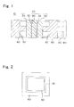
- Fig. 1 is a cross-sectional view illustrating a cell structure of a fuel cell according to an embodiment of the present invention
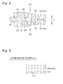
- Fig. 2 and Fig. 3 are a plan view and a cross-sectional view illustrating first and second gaskets that are disposed on both surfaces of a peripheral section of a polymer electrolyte membrane shown in Fig. 1 .
- a unit cell 10 shown in Fig. 1 is applied to a polymer electrolyte fuel cell (PEFC) which uses hydrogen as a fuel, or the like, and includes a membrane electrode assembly 20 and separators 80, 85. Furthermore, when the unit cells 10 are stacked to be used, for example, the unit cell 10 further has a cooling plate 90, and a recess 92 provided in the cooling panel 90 constitutes a coolant passage through which the coolant flows to cool the unit cell 10.
- PEFC polymer electrolyte fuel cell
- the membrane electrode assembly 20 has a polymer electrolyte membrane 30, catalyst layers 32 and 33, gas diffusion layers (GDL) 35 and 36, a first gasket 40, and a second gasket 60.
- GDL gas diffusion layers
- the catalyst layer 32 includes a catalyst component, electrically conductive catalyst carriers which carry the catalyst component, and a polymer electrolyte, and is an anode catalyst layer in which oxidation of hydrogen progresses, and is disposed on one side of the polymer electrolyte membrane 30.
- the catalyst layer 33 includes a catalyst component, electrically conductive catalyst carriers which carry the catalyst component, and a polymer electrolyte, is a cathode catalyst layer in which reduction of oxygen progresses, and is disposed on the other side of the polymer electrolyte membrane 30.
- the polymer electrolyte membrane 30 functions to cause protons generated in the catalyst layer 32 to be selectively transmitted to the catalyst layer 33, and functions as a barrier wall to separate a fuel gas supplied to an anode side thereof and an oxidizer gas supplied to a cathode side thereof.
- the gas diffusion layer 35 is an anode gas diffusion layer serving to diffuse the fuel gas supplied to the anode side and is positioned between the separator 80 and the catalyst layer 32.
- the gas diffusion layer 36 is a cathode gas diffusion layer serving to diffuse the oxidizer gas supplied to the cathode side and is positioned between the separator 85 and the catalyst layer 33.
- the first and second gaskets 40, 60 are frame-shaped and disposed respectively on both surfaces of an outer circumference portion of the polymer electrolyte membrane 30, as shown in Fig. 2 and Fig. 3 .
- the gasket 40 is positioned to surround the catalyst layer 32 and the gas diffusion layer 35, and functions to prevent the fuel gas supplied to the catalyst layer 32 from leaking externally.
- the gasket 60 is positioned to surround the catalyst layer 33 and the gas diffusion layer 36, and functions to prevent the oxidizer gas supplied to the catalyst layer 33 from leaking externally.
- the separators 80, 85 function to electrically connect the unit cells 10 to each other in series and function as a barrier wall to separate the fuel gas, the oxidizer gas, and the coolant from each other, and they have substantially the same shape as the membrane electrode assembly 20, and for example, are formed by press working a stainless steel sheet.
- the stainless steel sheet is preferable in that a complicated machine work is easily performed and electrical conductivity is high, and a coating for corrosion resistance may be applied to it, as necessary.
- the separator 80 is an anode separator disposed on the anode side of the membrane electrode assembly 20, faces the catalyst layer 32, and has a recess 82 constituting a gas passage which is positioned between the membrane electrode assembly 20 and the separator 80.
- the recess (gas passage) 82 is used for supplying the fuel gas to the catalyst layer 32.
- the separator 85 is a cathode separator disposed on the cathode side of the membrane electrode assembly 20, faces the catalyst layer 33, and has a recess 87 constituting a gas passage which is positioned between the membrane electrode assembly 20 and the separator 85.
- the recess (gas passage) 87 is used for supplying the oxidizer gas to the catalyst layer 33.
- a fluorine system polymer electrolyte membrane constituted by a perfluoro carbon sulfonic acid-based polymer, a hydrocarbon-based resin film having a sulfonic acid group, and a porous film which is impregnated with an electrolyte component such as phosphoric acid or ionic liquid may be applied.
- the perfluoro carbon sulfonic acid-based polymer may be Nafion (trademark, product made by Dupont Co., Ltd.), Aciplex (trademark, product made by Ashahi Kasei Co., Ltd.), or Flemion (trademark, product made by Ashahi Glass Co. , Ltd.).
- the porous film is formed from polytetrafluoroethylene (PTFE) or polyvinylidene fluoride (PVDF), for example.
- the thickness of the polymer electrolyte membrane 30 is not particularly limited, but preferably in a range of 5 ⁇ m to 300 ⁇ m, and more preferably in a range of 10 ⁇ m to 200 ⁇ m in view of strength, durability, and output characteristics.
- the catalyst component used in the catalyst layer (cathode catalyst layer) 35 is not particularly limited as long as the catalyst component performs catalytic action in the reduction of oxygen.
- the catalyst component used in the catalyst layer (anode catalyst layer) 34 is not particularly limited as long as the catalyst component has catalytic action in the oxidation of hydrogen.
- the specific catalyst component is selected from metals such as platinum, ruthenium, iridium, rhodium, palladium, osmium, tungsten, lead, iron, chrome, cobalt, nickel, manganese, vanadium, molybdenum, gallium, and aluminum, or alloys thereof, for example.
- the catalyst component preferably includes at least platinum in order to improve catalytic activity, poisoning resistance to carbon monoxide and the like, thermal resistance, and the like. It is not necessary that the catalyst components applied in the cathode catalyst layer and the anode catalyst layer be the same, and the catalyst components may be appropriately differentiated.
- the electrically conductive catalyst carrier used in the catalyst layers 32, 33 is not particularly limited as long as the electrically conductive catalyst carrier has a specific surface area for carrying the catalyst component in a desired diffusion state, and sufficient electron conductivity as a current collector, but the main component is preferably carbon particles.
- the carbon particles are formed from carbon black, activated carbon, coke, natural graphite, or artificial graphite, for example.
- the polymer electrolyte used in the catalyst layers 32, 33 is not particularly limited as long as the polymer electrolyte is a material which has at least high proton conductivity, and for example, a fluorine-based electrolyte including fluorine atoms in the entirety or a part of a polymer skeleton, or a hydrocarbon-based electrolyte not including fluorine atoms in a polymer skeleton may be applied.
- the polymer electrolyte used in the catalyst layers 32, 33 may be the same as or different from a polymer electrolyte used in the polymer electrolyte membrane 30, but preferably the same in view of improving adhesion of the catalyst layers 32, 33 to the polymer electrolyte membrane 30.
- the gas diffusion layers 35, 36 are formed by using as a base a sheet-shaped material which has electrical conductivity and a porous property such as a carbon-made textile such as a glassy carbon, a sheet-like paper body, felt, or non-woven fabric.
- the thickness of the base is not particularly limited, but preferably in a range of 30 ⁇ m to 500 ⁇ m in view of mechanical strength and permeability to gas, water, or the like.
- the base preferably includes a water repellent in view of water repellency and suppression of the flooding phenomenon.
- the water repellent may be, for example, a fluorine-based polymer material such as PTFE, PVDF, polyhexafluoropropylene, or tetrafluoroethylene-hexafluoropropylene copolymer (FEP), and polypropylene, polyethylene.
- a fluorine-based polymer material such as PTFE, PVDF, polyhexafluoropropylene, or tetrafluoroethylene-hexafluoropropylene copolymer (FEP), and polypropylene, polyethylene.
- the first and second gaskets 40, 60 are formed from rubber material, a fluorine-based polymer material, or thermoplastic resin, for example.
- the rubber material may be fluorine rubber, silicon rubber, ethylene propylene rubber (EPDM), polyisobutylene rubber, or the like.
- the fluorine-based polymer material may be PTFE, PVDF, polyhexafluoropropylene, FEP, or the like.
- the thermoplastic resin may be polyolefin, polyester, or the like. Polyester may be, for example, polyethylene naphthalate (PEN).
- the thickness of the first and second gaskets 40, 60 is not particularly limited, but preferably in a range of 50 ⁇ m to 2 mm, and more preferably in a range of 100 ⁇ m to 1 mm.
- the separators 80, 85 are not limited to the embodiment formed from stainless steel sheet, and other metal materials (for example, aluminum sheet or clad material) and carbon such as dense carbon graphite or a carbon board are also applicable.
- Recesses 82 and 87 may be formed by means of a cutting process or screen printing in a case where carbon is applied.
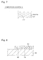
- Fig. 4 and Fig. 5 are a plan view and a cross-sectional view illustrating through holes of the first and second gaskets shown Fig. 2 and Fig. 3
- Fig. 6 and Fig. 7 are plan views illustrating Comparison Example 1 and Comparison Example 2 according to a bonding portion shown in Fig. 4 .
- the first and second gaskets 40, 60 have overlapping portions 42, 62 and bonding portions 52, 72.
- the overlapping portions 42, 62 are positioned at a peripheral edge 31 of the polymer electrolyte membrane 30 and face the polymer electrolyte membrane 30, and are provided with through holes 48, 68 are provided.
- the bonding portions 52, 72 are positioned outside of the peripheral edge 31 of the polymer electrolyte membrane 30 and bonded each other, and have inner sections 54, 74 where through holes 58, 78 are disposed, and outer sections 56, 76 which are positioned the outside of the inner sections 54, 74 and where no through hole is disposed. Furthermore, the bonding portions 52, 72 have a function of preventing that the first and second gaskets 40, 60 are detached from the polymer electrolyte membrane 30.
- the through holes 48, 68 and the through holes 58, 78 are minute, and extend in a thickness direction T of the polymer electrolyte membrane 30, and thus, influence in a direction perpendicular to the thickness direction T is suppressed.
- An aperture ratio of the through holes 48, 68 of the overlapping portions 42, 62 is set to be greater than an aperture ratio of the through holes 58, 78 of the bonding portions 52, 72.
- the aperture ratio of the through holes is adjusted, by changing the diameter (size) of the through holes. That is, the diameter of the through holes 48, 68 of the overlapping portions 42, 62 is greater than the diameter of the through holes 58, 78 of the bonding portions 52, 72, and thereby, it is easy to make the aperture ratio of the through holes 48, 68 of the overlapping portions 42, 62 greater than the aperture ratio of the through holes 58, 78 of the bonding portions 52, 72.
- the aperture ratio of the through holes is preferably 20% or less from the viewpoint of rigidity, and is preferably 0.2% or more from the viewpoint of the through hole effects.
- the aperture ratio of the through holes is preferably 20% or less from the viewpoint of rigidity, and is preferably 0.2% or more from the viewpoint of the through hole effects.
- the aperture ratio becomes approximately 20%
- the pitch interval is set to be ten times the diameter of the through holes
- the aperture ratio becomes approximately 0.1% to 1%
- the pitch interval is set to be a hundred times the diameter of the through holes
- the pitch interval is preferably two times to a hundred times the diameter, and when the diameter of the through holes is 10 ⁇ to 100 ⁇ , the pitch interval is preferably two times to ten times the diameter.
- a method for forming the through holes is not limited in particular, and it is possible to use a laser, a metal mold, or the like.
- the laser for example, by controlling laser output, spot diameter, scan timing, or the like, the position and the size of the through holes can be adjusted.
- the metal mold for example, it is possible to form melting holes by pressing a cavity face which is configured as a pinholder having minute protrusions, against a gasket raw material and heating it, and the position and the size of the through holes can be adjusted by changing the position and the size of the protrusions.
- the catalyst layers 32, 33 may be formed, as necessary, after the first and second gaskets 40, 60 are disposed and attached, or may be formed on the polymer electrolyte membrane 30 in advance.
- the gas diffusion layers 35, 36 may be disposed after being combined with the catalyst layers 32, 33, or may be separately disposed, for example, at the time of stacking the membrane electrode assembly 20.
- Fig. 8 , Fig. 9 , Fig. 10 , and Fig. 11 are a cross-sectional view illustrating an disposition of the second gasket, a cross-sectional view illustrating an disposition of the polymer electrolyte membrane, a cross-sectional view illustrating an disposition of the first gasket, and a plan view illustrating bubble removal by a squeegee, and Fig. 12 and Fig. 13 are cross-sectional views illustrating Comparison Example 1 and Comparison Example 2 according to the disposition of the first gasket.
- the mounting table 98 is composed of a porous member, is connected to an external vacuum source (not shown), and is adapted to be capable of sucking an object disposed thereon.
- the polymer electrolyte membrane 30 is disposed on the mounting table 98 and attached, and the peripheral edge 31 of the polymer electrolyte membrane 30 is positioned so as to overlap the second gasket 60.
- the overlapping portion 62 is formed on the second gasket 60.
- the peripheral edge 31 of the polymer electrolyte membrane 30 is sucked to the mounting table 98 through the through holes 68 formed in the overlapping portion 62 of the second gasket 60, curl-up of the peripheral edge 31 of the polymer electrolyte membrane 30 is suppressed, for example.
- the first gasket 40 is disposed on the mounting table 98 and is attached, and the first gasket 40 is positioned so as to overlap the peripheral edge 31 of the polymer electrolyte membrane 30.
- the overlapping portion 62 and the bonding portion 52 are formed on the first gasket 40 while the bonding portion 72 is formed on the second gasket 60.
- the aperture ratio of the through holes 48, 68 of the overlapping portions 42, 62 are set to be greater than the aperture ratio of the through holes 58, 78 of the bonding portions 52, 72, even when the electrolyte membrane 30 is interposed therebetween, the through holes 48, 68 of the overlapping portions 42, 62 exhibit a sufficient bubble removal function.
- the overlapping portions 42, 62, and the peripheral edge 31 of the polymer electrolyte membrane 30 are sufficiently bonded, and the remaining bubbles are suppressed.
- the fuel gas and the oxidant gas which are supplied to the catalyst layers 32, 33 is suppressed from externally leaking. That is, it is possible to provide the membrane electrode assembly 20 where an external leak of the fuel gas and the oxidant gas which are supplied to the catalyst layer is suppressed.
- suction has an influence up to the upper surface of the first gasket 140A, and it is difficult to accurately release the first gasket 140A toward the peripheral edge 31 of the polymer electrolyte membrane 30 (second gasket 160A).
- the first and second gaskets 40, 60 are pressed. Pressing by the squeegee 99 discharges bubbles (entrained air) remaining in a space S of the bonding portions 52, 72 and the overlapping portions 42, 62 through the through holes 48, 68 of the overlapping portions 42, 62 and the through holes 58, 78 of the bonding portions 52, 72.
- the squeegee 99 is formed from plastic, metal, or the like.
- the gasket does not have the through holes 48, 58, 68, and 78, it is difficult to remove the bubbles by using the squeegee.
- the squeegee is pressed against the gasket and applies pressure to extrude the bubbles, the bubbles are not removed because the shapes of the bubbles are only lengthened in a lateral direction, and the lengthened bubbles become a factor forming the leakage path of the gas.
- Fig. 14 is a plan view illustrating Modification according to an embodiment of the present invention.
- the aperture ratios of the through holes 48, 58, 68, and 78 may be also adjusted by changing density of the through holes 48, 58, 68, and 78.
- the density of the through holes 48, 68 of the overlapping portions 42, 62 is greater than the density of the through holes 58, 78 of the bonding portions 52, 72, and thereby, it is possible to easily adjust the aperture ratio.
- the overlapping portions and the bonding portions of the first and second gaskets have the through holes which extend in the thickness direction of the electrolyte membrane, after the first and second gaskets are disposed on the electrolyte membrane and are attached thereto, it is possible to remove bubbles remaining in spaces of the bonding portions and the overlapping portions, through the through holes. Moreover, at this time, since the aperture ratio of the through holes of the overlapping portions is greater than the aperture ratio of the through holes of the bonding portions, even when the peripheral edge of the electrolyte membrane is interposed therebetween, the through holes of the overlapping portions exhibits a sufficient bubble removal function.
- the aperture ratios of the through holes may be adjusted, by changing the size of the through holes, or the density of the through holes. For example, by making the size of the through holes of the overlapping portions to be greater than the size of the through holes of the bonding portions, or making the density of the through holes of the overlapping portions to be greater than the density of the through holes of the bonding portions, it is easily achieved that the aperture ratio of the through holes in the overlapping portion is to be greater than the aperture ratio of the through holes in the bonding portion.
- the aperture ratio of the through holes may be adapted so as to be sequentially decreased from the inside of the overlapping portions to the outside of the bonding portions.
- the fuel cell may be composed of a polymer electrolyte fuel cell which uses methanol as a fuel, or may be applied as a stationary power source.
- the polymer electrolyte fuel cell which uses methanol as a fuel may be a direct methanol fuel cell (DMFC), a micro fuel cell (passive type DMFC), or the like.
- Ethanol, 1-propanol, 2-propanol, primary butanol, secondary butanol, tertiary butanol, dimethyl ether, diethyl ether, ethylene glycol, diethylene glycol, or the like may be applied as a material other than hydrogen and methanol.
Landscapes
- Life Sciences & Earth Sciences (AREA)
- Engineering & Computer Science (AREA)
- Manufacturing & Machinery (AREA)
- Sustainable Development (AREA)
- Sustainable Energy (AREA)
- Chemical & Material Sciences (AREA)
- Chemical Kinetics & Catalysis (AREA)
- Electrochemistry (AREA)
- General Chemical & Material Sciences (AREA)
- Fuel Cell (AREA)
Abstract
Description
- The present invention relates to a membrane electrode assembly.
- A membrane electrode assembly (MEA) included in a unit cell of a fuel cell has a polymer electrolyte membrane where a catalyst layer is disposed, and a frame-shaped gasket disposed on both surfaces of the polymer electrolyte membrane. The gaskets are positioned so as to surround the catalyst layer of the polymer electrolyte membrane, and thus functions to prevent a fuel gas and an oxidizer gas supplied to the catalyst layer from leaking externally.
- However, when the gaskets are disposed on both surfaces of the polymer electrolyte membrane and are attached thereto, if bubbles remain between the gaskets and between the gasket and the polymer electrolyte membrane, they become a factor causing a gas leak in the manufactured membrane electrode assembly. On the other hand, a resin sheet having a through hole is known (for example, see PATENT LITERATURE 1).
- [PATENT LITERATURE 1] Japanese Patent No.
4898221 - However, the resin sheet according to
PATENT LITERATURE 1 is not intended to be used for a gasket, and even though it is applied to the gasket of the membrane electrode assembly, it is difficult to suppress the remaining bubbles. Hence, there is a concern that the fuel gas and the oxidant gas supplied to the catalyst layer leak out externally because a region which is surrounded by the gasket is communicated with a region which is positioned outside of a peripheral edge of the gasket via the remaining bubble, or because the remaining bubbles form a raised portion in the gasket, and thus, the adhesion properties of the gasket and a separator are reduced. - The present invention has been made to solve the aforementioned problem in the prior art, and aims to provide a membrane electrode assembly where an external leak of a fuel gas and an oxidant gas supplied to a catalyst layer, is suppressed.
- The present invention to achieve the abovementioned object is a membrane electrode assembly including an electrolyte membrane, and frame-shaped first and second gaskets disposed on both surfaces of the electrolyte membrane. The first and second gaskets have overlapping portions which are positioned at a peripheral edge of the electrolyte membrane and face the electrolyte membrane, and bonding portions which are positioned outside of the peripheral edge and bonded each other. The overlapping portions and the bonding portions have through holes which extend in a thickness direction of the electrolyte membrane, and an aperture ratio of the through holes of the overlapping portions is greater than an aperture ratio of the through holes of the bonding portions.
- According to the present invention, since the overlapping portions and the bonding portions of the first and second gaskets have the through holes which extend in the thickness direction of the electrolyte membrane, after the first and second gaskets are disposed on the electrolyte membrane and are attached thereto, it is possible to remove bubbles remaining in spaces of the bonding portions and the overlapping portions, through the through holes. Moreover, at this time, since the aperture ratio of the through holes of the overlapping portions is greater than the aperture ratio of the through holes of the bonding portions, even when the peripheral edge of the electrolyte membrane is interposed therebetween, the through holes of the overlapping portions exhibits a sufficient bubble removal function. Hereby, in the same manner as the bonding portion of the first gasket and the bonding portion of the second gasket where a polymer electrolyte membrane is not disposed, the overlapping portions and the peripheral edge of the electrolyte membrane are sufficiently bonded, and the remaining of the bubbles is suppressed. Hence, it is possible to provide a membrane electrode assembly where an external leak of a fuel gas and an oxidant gas supplied to a catalyst layer, is suppressed.
- The objects, features, and characteristics of this invention other than those set forth above will become apparent from the description given herein below with reference to preferred embodiments illustrated in the accompanying drawings.
-
-
Fig. 1 is a cross-sectional view illustrating a cell structure of a fuel cell according to an embodiment of the present invention. -
Fig. 2 is a plan view illustrating first and second gaskets that are disposed on both surfaces of a peripheral section of a polymer electrolyte membrane shown inFig. 1 . -
Fig. 3 is a cross-sectional view illustrating the first and second gaskets that are disposed on both surfaces of the peripheral section of the polymer electrolyte membrane shown inFig. 1 . -
Fig. 4 is a plan view illustrating through holes of the first and second gaskets shownFig. 2 andFig. 3 . -
Fig. 5 is a cross-sectional view illustrating the through holes of the first and second gaskets shownFig. 2 andFig. 3 . -
Fig. 6 is a plan view illustrating Comparison Example 1 according to a bonding portion shown inFig. 4 . -
Fig. 7 is a plan view illustrating Comparison Example 2 according to the bonding portion shown inFig. 4 . -
Fig. 8 is a cross-sectional view illustrating dispositions of the first and second gaskets in the polymer electrolyte membrane according to the embodiment of the present invention, and shows the disposition of the second gasket. -
Fig. 9 is a cross-sectional view illustrating the disposition of the polymer electrolyte membrane, following the disposition of the second gasket shown inFig. 8 . -
Fig. 10 is a cross-sectional view illustrating the disposition of the first gasket, following the disposition of the polymer electrolyte membrane. -
Fig. 11 is a plan view illustrating bubble removal by a squeegee, following the disposition of the first gasket. -
Fig. 12 is a cross-sectional view illustrating Comparison Example 1 according to the disposition of the first gasket. -
Fig. 13 is a cross-sectional view illustrating Comparison Example 2 according to the disposition of the first gasket. -
Fig. 14 is a plan view illustrating Modification according to the embodiment of the present invention. - Hereinafter, embodiments of the present invention will be described with reference to the drawings.
-
Fig. 1 is a cross-sectional view illustrating a cell structure of a fuel cell according to an embodiment of the present invention, andFig. 2 andFig. 3 are a plan view and a cross-sectional view illustrating first and second gaskets that are disposed on both surfaces of a peripheral section of a polymer electrolyte membrane shown inFig. 1 . - A
unit cell 10 shown inFig. 1 is applied to a polymer electrolyte fuel cell (PEFC) which uses hydrogen as a fuel, or the like, and includes amembrane electrode assembly 20 andseparators unit cells 10 are stacked to be used, for example, theunit cell 10 further has acooling plate 90, and arecess 92 provided in thecooling panel 90 constitutes a coolant passage through which the coolant flows to cool theunit cell 10. - The
membrane electrode assembly 20 has apolymer electrolyte membrane 30,catalyst layers first gasket 40, and asecond gasket 60. - The
catalyst layer 32 includes a catalyst component, electrically conductive catalyst carriers which carry the catalyst component, and a polymer electrolyte, and is an anode catalyst layer in which oxidation of hydrogen progresses, and is disposed on one side of thepolymer electrolyte membrane 30. Thecatalyst layer 33 includes a catalyst component, electrically conductive catalyst carriers which carry the catalyst component, and a polymer electrolyte, is a cathode catalyst layer in which reduction of oxygen progresses, and is disposed on the other side of thepolymer electrolyte membrane 30. - The
polymer electrolyte membrane 30 functions to cause protons generated in thecatalyst layer 32 to be selectively transmitted to thecatalyst layer 33, and functions as a barrier wall to separate a fuel gas supplied to an anode side thereof and an oxidizer gas supplied to a cathode side thereof. - The
gas diffusion layer 35 is an anode gas diffusion layer serving to diffuse the fuel gas supplied to the anode side and is positioned between theseparator 80 and thecatalyst layer 32. Thegas diffusion layer 36 is a cathode gas diffusion layer serving to diffuse the oxidizer gas supplied to the cathode side and is positioned between theseparator 85 and thecatalyst layer 33. - The first and
second gaskets polymer electrolyte membrane 30, as shown inFig. 2 andFig. 3 . Thegasket 40 is positioned to surround thecatalyst layer 32 and thegas diffusion layer 35, and functions to prevent the fuel gas supplied to thecatalyst layer 32 from leaking externally. Thegasket 60 is positioned to surround thecatalyst layer 33 and thegas diffusion layer 36, and functions to prevent the oxidizer gas supplied to thecatalyst layer 33 from leaking externally. - The
separators unit cells 10 to each other in series and function as a barrier wall to separate the fuel gas, the oxidizer gas, and the coolant from each other, and they have substantially the same shape as themembrane electrode assembly 20, and for example, are formed by press working a stainless steel sheet. The stainless steel sheet is preferable in that a complicated machine work is easily performed and electrical conductivity is high, and a coating for corrosion resistance may be applied to it, as necessary. - The
separator 80 is an anode separator disposed on the anode side of themembrane electrode assembly 20, faces thecatalyst layer 32, and has arecess 82 constituting a gas passage which is positioned between themembrane electrode assembly 20 and theseparator 80. The recess (gas passage) 82 is used for supplying the fuel gas to thecatalyst layer 32. - The
separator 85 is a cathode separator disposed on the cathode side of themembrane electrode assembly 20, faces thecatalyst layer 33, and has arecess 87 constituting a gas passage which is positioned between themembrane electrode assembly 20 and theseparator 85. The recess (gas passage) 87 is used for supplying the oxidizer gas to thecatalyst layer 33. - Next, the material, the size, and the like of each constituent member will be described in detail.
- As the
polymer electrolyte membrane 30, a fluorine system polymer electrolyte membrane constituted by a perfluoro carbon sulfonic acid-based polymer, a hydrocarbon-based resin film having a sulfonic acid group, and a porous film which is impregnated with an electrolyte component such as phosphoric acid or ionic liquid may be applied. The perfluoro carbon sulfonic acid-based polymer may be Nafion (trademark, product made by Dupont Co., Ltd.), Aciplex (trademark, product made by Ashahi Kasei Co., Ltd.), or Flemion (trademark, product made by Ashahi Glass Co. , Ltd.). The porous film is formed from polytetrafluoroethylene (PTFE) or polyvinylidene fluoride (PVDF), for example. - The thickness of the
polymer electrolyte membrane 30 is not particularly limited, but preferably in a range of 5 µm to 300 µm, and more preferably in a range of 10 µm to 200 µm in view of strength, durability, and output characteristics. - The catalyst component used in the catalyst layer (cathode catalyst layer) 35 is not particularly limited as long as the catalyst component performs catalytic action in the reduction of oxygen. The catalyst component used in the catalyst layer (anode catalyst layer) 34 is not particularly limited as long as the catalyst component has catalytic action in the oxidation of hydrogen.
- The specific catalyst component is selected from metals such as platinum, ruthenium, iridium, rhodium, palladium, osmium, tungsten, lead, iron, chrome, cobalt, nickel, manganese, vanadium, molybdenum, gallium, and aluminum, or alloys thereof, for example. The catalyst component preferably includes at least platinum in order to improve catalytic activity, poisoning resistance to carbon monoxide and the like, thermal resistance, and the like. It is not necessary that the catalyst components applied in the cathode catalyst layer and the anode catalyst layer be the same, and the catalyst components may be appropriately differentiated.
- The electrically conductive catalyst carrier used in the catalyst layers 32, 33 is not particularly limited as long as the electrically conductive catalyst carrier has a specific surface area for carrying the catalyst component in a desired diffusion state, and sufficient electron conductivity as a current collector, but the main component is preferably carbon particles. The carbon particles are formed from carbon black, activated carbon, coke, natural graphite, or artificial graphite, for example.
- The polymer electrolyte used in the catalyst layers 32, 33 is not particularly limited as long as the polymer electrolyte is a material which has at least high proton conductivity, and for example, a fluorine-based electrolyte including fluorine atoms in the entirety or a part of a polymer skeleton, or a hydrocarbon-based electrolyte not including fluorine atoms in a polymer skeleton may be applied. The polymer electrolyte used in the catalyst layers 32, 33 may be the same as or different from a polymer electrolyte used in the
polymer electrolyte membrane 30, but preferably the same in view of improving adhesion of the catalyst layers 32, 33 to thepolymer electrolyte membrane 30. - The gas diffusion layers 35, 36 are formed by using as a base a sheet-shaped material which has electrical conductivity and a porous property such as a carbon-made textile such as a glassy carbon, a sheet-like paper body, felt, or non-woven fabric. The thickness of the base is not particularly limited, but preferably in a range of 30 µm to 500 µm in view of mechanical strength and permeability to gas, water, or the like. In the gas diffusion layers 35, 36, the base preferably includes a water repellent in view of water repellency and suppression of the flooding phenomenon. The water repellent may be, for example, a fluorine-based polymer material such as PTFE, PVDF, polyhexafluoropropylene, or tetrafluoroethylene-hexafluoropropylene copolymer (FEP), and polypropylene, polyethylene.
- The first and
second gaskets second gaskets - The
separators Recesses - Next, the first and
second gaskets -
Fig. 4 andFig. 5 are a plan view and a cross-sectional view illustrating through holes of the first and second gaskets shownFig. 2 andFig. 3 , andFig. 6 andFig. 7 are plan views illustrating Comparison Example 1 and Comparison Example 2 according to a bonding portion shown inFig. 4 . - The first and
second gaskets portions bonding portions - The overlapping
portions peripheral edge 31 of thepolymer electrolyte membrane 30 and face thepolymer electrolyte membrane 30, and are provided with throughholes bonding portions peripheral edge 31 of thepolymer electrolyte membrane 30 and bonded each other, and haveinner sections holes outer sections inner sections bonding portions second gaskets polymer electrolyte membrane 30. - The through holes 48, 68 and the through
holes polymer electrolyte membrane 30, and thus, influence in a direction perpendicular to the thickness direction T is suppressed. An aperture ratio of the throughholes portions holes bonding portions - In the present embodiment, the aperture ratio of the through holes is adjusted, by changing the diameter (size) of the through holes. That is, the diameter of the through
holes portions holes bonding portions holes portions holes bonding portions - In the
outer sections bonding portions cracks 177 are generated and enlarged along throughholes 157, orouter sections Fig. 6 and Comparison Example 2 ofFig. 7 . - The aperture ratio of the through holes is preferably 20% or less from the viewpoint of rigidity, and is preferably 0.2% or more from the viewpoint of the through hole effects. For example, when the through holes are disposed in a rectangular formation, if a pitch interval is set to be two times the diameter of the through holes, the aperture ratio becomes approximately 20%, if the pitch interval is set to be ten times the diameter of the through holes, the aperture ratio becomes approximately 0.1% to 1%, and if the pitch interval is set to be a hundred times the diameter of the through holes, the aperture ratio becomes approximately 0.001% to 0.01%.
- When the diameter of the through holes is 0.1 µ to 10 µ, the pitch interval is preferably two times to a hundred times the diameter, and when the diameter of the through holes is 10 µ to 100 µ, the pitch interval is preferably two times to ten times the diameter.
- A method for forming the through holes is not limited in particular, and it is possible to use a laser, a metal mold, or the like. In the case of the laser, for example, by controlling laser output, spot diameter, scan timing, or the like, the position and the size of the through holes can be adjusted. In the case of the metal mold, for example, it is possible to form melting holes by pressing a cavity face which is configured as a pinholder having minute protrusions, against a gasket raw material and heating it, and the position and the size of the through holes can be adjusted by changing the position and the size of the protrusions.
- The catalyst layers 32, 33 may be formed, as necessary, after the first and
second gaskets polymer electrolyte membrane 30 in advance. The gas diffusion layers 35, 36 may be disposed after being combined with the catalyst layers 32, 33, or may be separately disposed, for example, at the time of stacking themembrane electrode assembly 20. - Next, actions and effects of the through holes at the time of disposing the first and second gaskets in the membrane electrode assembly will be described.
-
Fig. 8 ,Fig. 9 ,Fig. 10 , andFig. 11 are a cross-sectional view illustrating an disposition of the second gasket, a cross-sectional view illustrating an disposition of the polymer electrolyte membrane, a cross-sectional view illustrating an disposition of the first gasket, and a plan view illustrating bubble removal by a squeegee, andFig. 12 andFig. 13 are cross-sectional views illustrating Comparison Example 1 and Comparison Example 2 according to the disposition of the first gasket. - When the first and
second gaskets polymer electrolyte membrane 30, firstly, thesecond gasket 60 is disposed on a mounting table 98 as shown inFig. 8 . The mounting table 98 is composed of a porous member, is connected to an external vacuum source (not shown), and is adapted to be capable of sucking an object disposed thereon. - Then, as shown in
Fig. 9 , thepolymer electrolyte membrane 30 is disposed on the mounting table 98 and attached, and theperipheral edge 31 of thepolymer electrolyte membrane 30 is positioned so as to overlap thesecond gasket 60. Hereby, the overlappingportion 62 is formed on thesecond gasket 60. At this time, since theperipheral edge 31 of thepolymer electrolyte membrane 30 is sucked to the mounting table 98 through the throughholes 68 formed in the overlappingportion 62 of thesecond gasket 60, curl-up of theperipheral edge 31 of thepolymer electrolyte membrane 30 is suppressed, for example. - Thereafter, as shown in
Fig. 10 , thefirst gasket 40 is disposed on the mounting table 98 and is attached, and thefirst gasket 40 is positioned so as to overlap theperipheral edge 31 of thepolymer electrolyte membrane 30. Hereby, the overlappingportion 62 and thebonding portion 52 are formed on thefirst gasket 40 while thebonding portion 72 is formed on thesecond gasket 60. - At this time, since the aperture ratio of the through
holes portions holes bonding portions electrolyte membrane 30 is interposed therebetween, the throughholes portions bonding portions polymer electrolyte membrane 30 is not disposed, the overlappingportions peripheral edge 31 of thepolymer electrolyte membrane 30 are sufficiently bonded, and the remaining bubbles are suppressed. - Consequently, since it is avoided that a region surrounded by the first and
second gaskets outer sections second gaskets second gaskets separators membrane electrode assembly 20 where an external leak of the fuel gas and the oxidant gas which are supplied to the catalyst layer is suppressed. - On the other hand, when the through hole is not formed as a
first gasket 140 and asecond gasket 160 of Comparison Example 1 shown inFig. 12 , the curl-up is generated at theperipheral edge 31 of thepolymer electrolyte membrane 30 and, thus, it is difficult to suitably dispose and attach thefirst gasket 140. - Moreover, when through
holes first gasket 140A and asecond gasket 160A of Comparison Example 2 shown inFig. 13 , suction (vacuum) has an influence up to the upper surface of thefirst gasket 140A, and it is difficult to accurately release thefirst gasket 140A toward theperipheral edge 31 of the polymer electrolyte membrane 30 (second gasket 160A). - As necessary, after the disposition of the first gasket, it is possible to use bubble removal by the squeegee together. In this case, for example, as shown in
Fig. 11 , by moving asqueegee 99 while sucking by the mounting table 98, the first andsecond gaskets squeegee 99 discharges bubbles (entrained air) remaining in a space S of thebonding portions portions holes portions holes bonding portions squeegee 99 is formed from plastic, metal, or the like. - Furthermore, when the gasket does not have the through
holes -
Fig. 14 is a plan view illustrating Modification according to an embodiment of the present invention. - The aperture ratios of the through
holes holes Fig. 14 , the density of the throughholes portions holes bonding portions - As described above, in the embodiments of the present invention, since the overlapping portions and the bonding portions of the first and second gaskets have the through holes which extend in the thickness direction of the electrolyte membrane, after the first and second gaskets are disposed on the electrolyte membrane and are attached thereto, it is possible to remove bubbles remaining in spaces of the bonding portions and the overlapping portions, through the through holes. Moreover, at this time, since the aperture ratio of the through holes of the overlapping portions is greater than the aperture ratio of the through holes of the bonding portions, even when the peripheral edge of the electrolyte membrane is interposed therebetween, the through holes of the overlapping portions exhibits a sufficient bubble removal function. Hereby, in the same manner as the bonding portion of the first gasket and the bonding portion of the second gasket where a polymer electrolyte membrane is not disposed, the overlapping portions and the peripheral edge of the electrolyte membrane are sufficiently bonded, and the remaining of the bubbles is suppressed. Hence, it is possible to provide a membrane electrode assembly where an external leak of a fuel gas and an oxidant gas supplied to a catalyst layer, is suppressed.
- The aperture ratios of the through holes may be adjusted, by changing the size of the through holes, or the density of the through holes. For example, by making the size of the through holes of the overlapping portions to be greater than the size of the through holes of the bonding portions, or making the density of the through holes of the overlapping portions to be greater than the density of the through holes of the bonding portions, it is easily achieved that the aperture ratio of the through holes in the overlapping portion is to be greater than the aperture ratio of the through holes in the bonding portion.
- When no through hole is disposed in the outer sections of the bonding portions, it can be prevented that the crack is enlarged along the through hole, or the outer section is split off.
- The present invention is not limited to the above embodiment, but can be modified in various forms within the range of the claims.
- For example, the aperture ratio of the through holes may be adapted so as to be sequentially decreased from the inside of the overlapping portions to the outside of the bonding portions. Moreover, the fuel cell may be composed of a polymer electrolyte fuel cell which uses methanol as a fuel, or may be applied as a stationary power source. The polymer electrolyte fuel cell which uses methanol as a fuel may be a direct methanol fuel cell (DMFC), a micro fuel cell (passive type DMFC), or the like. Ethanol, 1-propanol, 2-propanol, primary butanol, secondary butanol, tertiary butanol, dimethyl ether, diethyl ether, ethylene glycol, diethylene glycol, or the like may be applied as a material other than hydrogen and methanol.
- The present application is based on the Japanese Patent Application No.
2012-154961 filed July 10, 2012 -
- 10
- unit cell,
- 20
- membrane electrode assembly,
- 30
- polymer electrolyte membrane,
- 31
- peripheral edge,
- 32, 33
- catalyst layer,
- 35, 36
- gas diffusion layer,
- 40, 140, 140a
- first gasket,
- 42
- overlapping portion,
- 48
- through hole,
- 52
- bonding portion,
- 54
- inner section,
- 56
- outer section,
- 58
- through hole,
- 60, 160, 160a
- second gasket,
- 62
- overlapping portion,
- 68
- through hole,
- 72
- bonding portion,
- 74
- inner section,
- 76
- outer section,
- 78
- through hole,
- 80, 85
- separator,
- 82, 87
- recess
- 90
- cooling plate,
- 92
- recess,
- 98
- mounting table,
- 99
- squeegee,
- 156, 176
- outer section,
- 157, 158, 178
- through hole,
- 177
- crack,
- t
- thickness direction,
- s
- space,
Claims (4)
- A membrane electrode assembly comprising:an electrolyte membrane; andframe-shaped first and second gaskets disposed on both surfaces of the electrolyte membrane,wherein said first and second gaskets have overlapping portions which are positioned at a peripheral edge of said electrolyte membrane and face said electrolyte membrane, and bonding portions which are positioned outside of the peripheral edge and bonded each other,said overlapping portions and said bonding portions have through holes which extend in a thickness direction of said electrolyte membrane, andan aperture ratio of the through holes of said overlapping portions is greater than an aperture ratio of the through holes of said bonding portions.
- The membrane electrode assembly according to claim 1, wherein a size of the through holes of said overlapping portions is greater than a size of the through holes of said bonding portions.
- The membrane electrode assembly according to claim 1 or 2, wherein density of the through holes of said overlapping portions is greater than density of the through holes of said bonding portions.
- The membrane electrode assembly according to any one of claims 1 to 3, wherein said bonding portions have inner sections where the through holes are disposed, and outer sections which are positioned outside said inner section and where no through hole is disposed.
Applications Claiming Priority (2)
| Application Number | Priority Date | Filing Date | Title |
|---|---|---|---|
| JP2012154961 | 2012-07-10 | ||
| PCT/JP2013/067276 WO2014010399A1 (en) | 2012-07-10 | 2013-06-24 | Membrane electrode assembly |
Publications (3)
| Publication Number | Publication Date |
|---|---|
| EP2874219A1 true EP2874219A1 (en) | 2015-05-20 |
| EP2874219A4 EP2874219A4 (en) | 2015-07-22 |
| EP2874219B1 EP2874219B1 (en) | 2016-11-30 |
Family
ID=49915865
Family Applications (1)
| Application Number | Title | Priority Date | Filing Date |
|---|---|---|---|
| EP13816315.9A Not-in-force EP2874219B1 (en) | 2012-07-10 | 2013-06-24 | Membrane electrode assembly |
Country Status (6)
| Country | Link |
|---|---|
| US (1) | US9219282B2 (en) |
| EP (1) | EP2874219B1 (en) |
| JP (1) | JP5854139B2 (en) |
| CN (1) | CN104428932B (en) |
| CA (1) | CA2878834C (en) |
| WO (1) | WO2014010399A1 (en) |
Cited By (1)
| Publication number | Priority date | Publication date | Assignee | Title |
|---|---|---|---|---|
| WO2023078819A3 (en) * | 2021-11-03 | 2023-11-16 | Robert Bosch Gmbh | Membrane-electrode assembly for an electrochemical cell and method for producing a membrane-electrode assembly |
Families Citing this family (3)
| Publication number | Priority date | Publication date | Assignee | Title |
|---|---|---|---|---|
| JP6085935B2 (en) * | 2012-09-28 | 2017-03-01 | 大日本印刷株式会社 | REINFORCED CATALYST LAYER-ELECTROLYTE MEMBRANE LAMINATE, SOLID POLYMER FUEL CELL AND METHOD FOR PRODUCING REINFORCING CATALYST LAYER-ELECTROLYTE MEMBRANE |
| JP2018185977A (en) * | 2017-04-26 | 2018-11-22 | 株式会社Soken | Fuel cell |
| JP6996396B2 (en) * | 2018-04-04 | 2022-01-17 | トヨタ自動車株式会社 | How to make a fuel cell |
Family Cites Families (12)
| Publication number | Priority date | Publication date | Assignee | Title |
|---|---|---|---|---|
| AU664703B2 (en) | 1991-06-04 | 1995-11-30 | Ballard Power Systems Inc. | Gasketed membrane electrode assembly for electrochemical fuel cells |
| US7226686B2 (en) * | 2001-04-23 | 2007-06-05 | Nok Corporation | Fuel cell and method of manufacturing the fuel cell |
| WO2004061031A1 (en) | 2002-12-27 | 2004-07-22 | Lintec Corporation | Pressure sensitive adhesive sheet and method of manufacturing the adhesive sheet |
| US20050095490A1 (en) * | 2003-10-31 | 2005-05-05 | Mittelstadt Laurie S. | Fuel cell assembly gasket for fuel containment |
| JP2005302526A (en) | 2004-04-12 | 2005-10-27 | Asahi Glass Co Ltd | Solid polymer electrolyte membrane and membrane electrode assembly having solid polymer electrolyte membrane |
| JP4965833B2 (en) * | 2004-08-30 | 2012-07-04 | 旭硝子株式会社 | Solid polymer electrolyte membrane electrode assembly and solid polymer fuel cell |
| KR101232396B1 (en) | 2004-08-30 | 2013-02-12 | 파나소닉 주식회사 | Membrane electrode assembly for solid polymer fuel cell and solid polymer fuel cell |
| JP2006331700A (en) * | 2005-05-23 | 2006-12-07 | Toyota Motor Corp | Fuel cell |
| JP2007335353A (en) * | 2006-06-19 | 2007-12-27 | Toyota Motor Corp | Fuel cell |
| US7732083B2 (en) * | 2006-12-15 | 2010-06-08 | 3M Innovative Properties Company | Gas diffusion layer incorporating a gasket |
| JP2010115663A (en) * | 2008-11-11 | 2010-05-27 | Nissan Motor Co Ltd | Method and apparatus for joining base material |
| US20110177423A1 (en) | 2010-01-21 | 2011-07-21 | Anton Nachtmann | Five-Layer Membrane Electrode Assembly with Attached Border and Method of Making Same |
-
2013
- 2013-06-24 US US14/413,511 patent/US9219282B2/en not_active Expired - Fee Related
- 2013-06-24 JP JP2014524716A patent/JP5854139B2/en not_active Expired - Fee Related
- 2013-06-24 WO PCT/JP2013/067276 patent/WO2014010399A1/en not_active Ceased
- 2013-06-24 EP EP13816315.9A patent/EP2874219B1/en not_active Not-in-force
- 2013-06-24 CA CA2878834A patent/CA2878834C/en not_active Expired - Fee Related
- 2013-06-24 CN CN201380036242.XA patent/CN104428932B/en not_active Expired - Fee Related
Cited By (1)
| Publication number | Priority date | Publication date | Assignee | Title |
|---|---|---|---|---|
| WO2023078819A3 (en) * | 2021-11-03 | 2023-11-16 | Robert Bosch Gmbh | Membrane-electrode assembly for an electrochemical cell and method for producing a membrane-electrode assembly |
Also Published As
| Publication number | Publication date |
|---|---|
| CA2878834C (en) | 2016-01-05 |
| JPWO2014010399A1 (en) | 2016-06-20 |
| CN104428932B (en) | 2016-04-20 |
| EP2874219B1 (en) | 2016-11-30 |
| US20150188151A1 (en) | 2015-07-02 |
| EP2874219A4 (en) | 2015-07-22 |
| CN104428932A (en) | 2015-03-18 |
| CA2878834A1 (en) | 2014-01-16 |
| JP5854139B2 (en) | 2016-02-09 |
| US9219282B2 (en) | 2015-12-22 |
| WO2014010399A1 (en) | 2014-01-16 |
Similar Documents
| Publication | Publication Date | Title |
|---|---|---|
| US9331345B2 (en) | Bonded sheet and sheet-member bonding method | |
| KR101620155B1 (en) | Fuel cell and manufacturing method thereof | |
| JP5326189B2 (en) | Electrolyte membrane-electrode assembly and method for producing the same | |
| US9539730B2 (en) | Holding apparatus for fuel cell electrolyte membrane | |
| JP2009193860A (en) | Membrane electrode assembly for polymer electrolyte fuel cell and method for producing the same | |
| EP2874219B1 (en) | Membrane electrode assembly | |
| US9789682B2 (en) | Metal mask and screen printing apparatus | |
| CA2878826C (en) | Holding apparatus for fuel cell gasket | |
| JP2006338939A (en) | Electrolyte membrane-electrode assembly | |
| JP2006338942A (en) | Electrolyte membrane-electrode assembly and fuel cell | |
| JP2006338941A (en) | Electrolyte membrane-electrode assembly |
Legal Events
| Date | Code | Title | Description |
|---|---|---|---|
| PUAI | Public reference made under article 153(3) epc to a published international application that has entered the european phase |
Free format text: ORIGINAL CODE: 0009012 |
|
| 17P | Request for examination filed |
Effective date: 20150203 |
|
| AK | Designated contracting states |
Kind code of ref document: A1 Designated state(s): AL AT BE BG CH CY CZ DE DK EE ES FI FR GB GR HR HU IE IS IT LI LT LU LV MC MK MT NL NO PL PT RO RS SE SI SK SM TR |
|
| AX | Request for extension of the european patent |
Extension state: BA ME |
|
| RA4 | Supplementary search report drawn up and despatched (corrected) |
Effective date: 20150624 |
|
| RIC1 | Information provided on ipc code assigned before grant |
Ipc: H01M 8/02 20060101AFI20150618BHEP Ipc: H01M 8/10 20060101ALI20150618BHEP |
|
| DAX | Request for extension of the european patent (deleted) | ||
| 17Q | First examination report despatched |
Effective date: 20151123 |
|
| REG | Reference to a national code |
Ref country code: DE Ref legal event code: R079 Ref document number: 602013014881 Country of ref document: DE Free format text: PREVIOUS MAIN CLASS: H01M0008020000 Ipc: H01M0008101800 |
|
| GRAJ | Information related to disapproval of communication of intention to grant by the applicant or resumption of examination proceedings by the epo deleted |
Free format text: ORIGINAL CODE: EPIDOSDIGR1 |
|
| GRAP | Despatch of communication of intention to grant a patent |
Free format text: ORIGINAL CODE: EPIDOSNIGR1 |
|
| GRAJ | Information related to disapproval of communication of intention to grant by the applicant or resumption of examination proceedings by the epo deleted |
Free format text: ORIGINAL CODE: EPIDOSDIGR1 |
|
| GRAP | Despatch of communication of intention to grant a patent |
Free format text: ORIGINAL CODE: EPIDOSNIGR1 |
|
| RIC1 | Information provided on ipc code assigned before grant |
Ipc: H01M 8/1018 20160101AFI20160607BHEP Ipc: H01M 8/0284 20160101ALN20160607BHEP Ipc: H01M 8/0273 20160101ALI20160607BHEP |
|
| INTG | Intention to grant announced |
Effective date: 20160620 |
|
| RIN1 | Information on inventor provided before grant (corrected) |
Inventor name: ONO, KEI Inventor name: HORIBE, NORIFUMI Inventor name: TERASAKI, TAKAYUKI Inventor name: TOYOSHIMA, KENICHI Inventor name: YAMAMOTO, MASAYA |
|
| INTG | Intention to grant announced |
Effective date: 20160712 |
|
| GRAS | Grant fee paid |
Free format text: ORIGINAL CODE: EPIDOSNIGR3 |
|
| GRAA | (expected) grant |
Free format text: ORIGINAL CODE: 0009210 |
|
| AK | Designated contracting states |
Kind code of ref document: B1 Designated state(s): AL AT BE BG CH CY CZ DE DK EE ES FI FR GB GR HR HU IE IS IT LI LT LU LV MC MK MT NL NO PL PT RO RS SE SI SK SM TR |
|
| REG | Reference to a national code |
Ref country code: CH Ref legal event code: EP Ref country code: GB Ref legal event code: FG4D |
|
| REG | Reference to a national code |
Ref country code: AT Ref legal event code: REF Ref document number: 850580 Country of ref document: AT Kind code of ref document: T Effective date: 20161215 |
|
| REG | Reference to a national code |
Ref country code: IE Ref legal event code: FG4D |
|
| REG | Reference to a national code |
Ref country code: DE Ref legal event code: R096 Ref document number: 602013014881 Country of ref document: DE |
|
| PG25 | Lapsed in a contracting state [announced via postgrant information from national office to epo] |
Ref country code: LV Free format text: LAPSE BECAUSE OF FAILURE TO SUBMIT A TRANSLATION OF THE DESCRIPTION OR TO PAY THE FEE WITHIN THE PRESCRIBED TIME-LIMIT Effective date: 20161130 |
|
| REG | Reference to a national code |
Ref country code: LT Ref legal event code: MG4D |
|
| REG | Reference to a national code |
Ref country code: NL Ref legal event code: MP Effective date: 20161130 |
|
| REG | Reference to a national code |
Ref country code: AT Ref legal event code: MK05 Ref document number: 850580 Country of ref document: AT Kind code of ref document: T Effective date: 20161130 |
|
| PG25 | Lapsed in a contracting state [announced via postgrant information from national office to epo] |
Ref country code: GR Free format text: LAPSE BECAUSE OF FAILURE TO SUBMIT A TRANSLATION OF THE DESCRIPTION OR TO PAY THE FEE WITHIN THE PRESCRIBED TIME-LIMIT Effective date: 20170301 Ref country code: NO Free format text: LAPSE BECAUSE OF FAILURE TO SUBMIT A TRANSLATION OF THE DESCRIPTION OR TO PAY THE FEE WITHIN THE PRESCRIBED TIME-LIMIT Effective date: 20170228 Ref country code: LT Free format text: LAPSE BECAUSE OF FAILURE TO SUBMIT A TRANSLATION OF THE DESCRIPTION OR TO PAY THE FEE WITHIN THE PRESCRIBED TIME-LIMIT Effective date: 20161130 Ref country code: SE Free format text: LAPSE BECAUSE OF FAILURE TO SUBMIT A TRANSLATION OF THE DESCRIPTION OR TO PAY THE FEE WITHIN THE PRESCRIBED TIME-LIMIT Effective date: 20161130 |
|
| REG | Reference to a national code |
Ref country code: FR Ref legal event code: PLFP Year of fee payment: 5 |
|
| PG25 | Lapsed in a contracting state [announced via postgrant information from national office to epo] |
Ref country code: PT Free format text: LAPSE BECAUSE OF FAILURE TO SUBMIT A TRANSLATION OF THE DESCRIPTION OR TO PAY THE FEE WITHIN THE PRESCRIBED TIME-LIMIT Effective date: 20170330 Ref country code: ES Free format text: LAPSE BECAUSE OF FAILURE TO SUBMIT A TRANSLATION OF THE DESCRIPTION OR TO PAY THE FEE WITHIN THE PRESCRIBED TIME-LIMIT Effective date: 20161130 Ref country code: RS Free format text: LAPSE BECAUSE OF FAILURE TO SUBMIT A TRANSLATION OF THE DESCRIPTION OR TO PAY THE FEE WITHIN THE PRESCRIBED TIME-LIMIT Effective date: 20161130 Ref country code: PL Free format text: LAPSE BECAUSE OF FAILURE TO SUBMIT A TRANSLATION OF THE DESCRIPTION OR TO PAY THE FEE WITHIN THE PRESCRIBED TIME-LIMIT Effective date: 20161130 Ref country code: FI Free format text: LAPSE BECAUSE OF FAILURE TO SUBMIT A TRANSLATION OF THE DESCRIPTION OR TO PAY THE FEE WITHIN THE PRESCRIBED TIME-LIMIT Effective date: 20161130 Ref country code: HR Free format text: LAPSE BECAUSE OF FAILURE TO SUBMIT A TRANSLATION OF THE DESCRIPTION OR TO PAY THE FEE WITHIN THE PRESCRIBED TIME-LIMIT Effective date: 20161130 Ref country code: AT Free format text: LAPSE BECAUSE OF FAILURE TO SUBMIT A TRANSLATION OF THE DESCRIPTION OR TO PAY THE FEE WITHIN THE PRESCRIBED TIME-LIMIT Effective date: 20161130 |
|
| PG25 | Lapsed in a contracting state [announced via postgrant information from national office to epo] |
Ref country code: NL Free format text: LAPSE BECAUSE OF FAILURE TO SUBMIT A TRANSLATION OF THE DESCRIPTION OR TO PAY THE FEE WITHIN THE PRESCRIBED TIME-LIMIT Effective date: 20161130 |
|
| PG25 | Lapsed in a contracting state [announced via postgrant information from national office to epo] |
Ref country code: SK Free format text: LAPSE BECAUSE OF FAILURE TO SUBMIT A TRANSLATION OF THE DESCRIPTION OR TO PAY THE FEE WITHIN THE PRESCRIBED TIME-LIMIT Effective date: 20161130 Ref country code: RO Free format text: LAPSE BECAUSE OF FAILURE TO SUBMIT A TRANSLATION OF THE DESCRIPTION OR TO PAY THE FEE WITHIN THE PRESCRIBED TIME-LIMIT Effective date: 20161130 Ref country code: CZ Free format text: LAPSE BECAUSE OF FAILURE TO SUBMIT A TRANSLATION OF THE DESCRIPTION OR TO PAY THE FEE WITHIN THE PRESCRIBED TIME-LIMIT Effective date: 20161130 Ref country code: EE Free format text: LAPSE BECAUSE OF FAILURE TO SUBMIT A TRANSLATION OF THE DESCRIPTION OR TO PAY THE FEE WITHIN THE PRESCRIBED TIME-LIMIT Effective date: 20161130 Ref country code: DK Free format text: LAPSE BECAUSE OF FAILURE TO SUBMIT A TRANSLATION OF THE DESCRIPTION OR TO PAY THE FEE WITHIN THE PRESCRIBED TIME-LIMIT Effective date: 20161130 |
|
| PG25 | Lapsed in a contracting state [announced via postgrant information from national office to epo] |
Ref country code: BG Free format text: LAPSE BECAUSE OF FAILURE TO SUBMIT A TRANSLATION OF THE DESCRIPTION OR TO PAY THE FEE WITHIN THE PRESCRIBED TIME-LIMIT Effective date: 20170228 Ref country code: SM Free format text: LAPSE BECAUSE OF FAILURE TO SUBMIT A TRANSLATION OF THE DESCRIPTION OR TO PAY THE FEE WITHIN THE PRESCRIBED TIME-LIMIT Effective date: 20161130 Ref country code: BE Free format text: LAPSE BECAUSE OF FAILURE TO SUBMIT A TRANSLATION OF THE DESCRIPTION OR TO PAY THE FEE WITHIN THE PRESCRIBED TIME-LIMIT Effective date: 20161130 Ref country code: IT Free format text: LAPSE BECAUSE OF FAILURE TO SUBMIT A TRANSLATION OF THE DESCRIPTION OR TO PAY THE FEE WITHIN THE PRESCRIBED TIME-LIMIT Effective date: 20161130 |
|
| REG | Reference to a national code |
Ref country code: DE Ref legal event code: R097 Ref document number: 602013014881 Country of ref document: DE |
|
| PLBE | No opposition filed within time limit |
Free format text: ORIGINAL CODE: 0009261 |
|
| STAA | Information on the status of an ep patent application or granted ep patent |
Free format text: STATUS: NO OPPOSITION FILED WITHIN TIME LIMIT |
|
| 26N | No opposition filed |
Effective date: 20170831 |
|
| PG25 | Lapsed in a contracting state [announced via postgrant information from national office to epo] |
Ref country code: SI Free format text: LAPSE BECAUSE OF FAILURE TO SUBMIT A TRANSLATION OF THE DESCRIPTION OR TO PAY THE FEE WITHIN THE PRESCRIBED TIME-LIMIT Effective date: 20161130 |
|
| PG25 | Lapsed in a contracting state [announced via postgrant information from national office to epo] |
Ref country code: MC Free format text: LAPSE BECAUSE OF FAILURE TO SUBMIT A TRANSLATION OF THE DESCRIPTION OR TO PAY THE FEE WITHIN THE PRESCRIBED TIME-LIMIT Effective date: 20161130 |
|
| REG | Reference to a national code |
Ref country code: CH Ref legal event code: PL |
|
| REG | Reference to a national code |
Ref country code: IE Ref legal event code: MM4A |
|
| PG25 | Lapsed in a contracting state [announced via postgrant information from national office to epo] |
Ref country code: IE Free format text: LAPSE BECAUSE OF NON-PAYMENT OF DUE FEES Effective date: 20170624 Ref country code: CH Free format text: LAPSE BECAUSE OF NON-PAYMENT OF DUE FEES Effective date: 20170630 Ref country code: LI Free format text: LAPSE BECAUSE OF NON-PAYMENT OF DUE FEES Effective date: 20170630 Ref country code: LU Free format text: LAPSE BECAUSE OF NON-PAYMENT OF DUE FEES Effective date: 20170624 |
|
| REG | Reference to a national code |
Ref country code: FR Ref legal event code: PLFP Year of fee payment: 6 |
|
| PG25 | Lapsed in a contracting state [announced via postgrant information from national office to epo] |
Ref country code: MT Free format text: LAPSE BECAUSE OF NON-PAYMENT OF DUE FEES Effective date: 20170624 |
|
| PG25 | Lapsed in a contracting state [announced via postgrant information from national office to epo] |
Ref country code: HU Free format text: LAPSE BECAUSE OF FAILURE TO SUBMIT A TRANSLATION OF THE DESCRIPTION OR TO PAY THE FEE WITHIN THE PRESCRIBED TIME-LIMIT; INVALID AB INITIO Effective date: 20130624 |
|
| PGFP | Annual fee paid to national office [announced via postgrant information from national office to epo] |
Ref country code: DE Payment date: 20190612 Year of fee payment: 7 |
|
| PGFP | Annual fee paid to national office [announced via postgrant information from national office to epo] |
Ref country code: FR Payment date: 20190510 Year of fee payment: 7 |
|
| PG25 | Lapsed in a contracting state [announced via postgrant information from national office to epo] |
Ref country code: CY Free format text: LAPSE BECAUSE OF FAILURE TO SUBMIT A TRANSLATION OF THE DESCRIPTION OR TO PAY THE FEE WITHIN THE PRESCRIBED TIME-LIMIT Effective date: 20161130 |
|
| PGFP | Annual fee paid to national office [announced via postgrant information from national office to epo] |
Ref country code: GB Payment date: 20190619 Year of fee payment: 7 |
|
| PG25 | Lapsed in a contracting state [announced via postgrant information from national office to epo] |
Ref country code: MK Free format text: LAPSE BECAUSE OF FAILURE TO SUBMIT A TRANSLATION OF THE DESCRIPTION OR TO PAY THE FEE WITHIN THE PRESCRIBED TIME-LIMIT Effective date: 20161130 |
|
| PG25 | Lapsed in a contracting state [announced via postgrant information from national office to epo] |
Ref country code: TR Free format text: LAPSE BECAUSE OF FAILURE TO SUBMIT A TRANSLATION OF THE DESCRIPTION OR TO PAY THE FEE WITHIN THE PRESCRIBED TIME-LIMIT Effective date: 20161130 |
|
| PG25 | Lapsed in a contracting state [announced via postgrant information from national office to epo] |
Ref country code: AL Free format text: LAPSE BECAUSE OF FAILURE TO SUBMIT A TRANSLATION OF THE DESCRIPTION OR TO PAY THE FEE WITHIN THE PRESCRIBED TIME-LIMIT Effective date: 20161130 Ref country code: IS Free format text: LAPSE BECAUSE OF FAILURE TO SUBMIT A TRANSLATION OF THE DESCRIPTION OR TO PAY THE FEE WITHIN THE PRESCRIBED TIME-LIMIT Effective date: 20170330 |
|
| REG | Reference to a national code |
Ref country code: DE Ref legal event code: R119 Ref document number: 602013014881 Country of ref document: DE |
|
| GBPC | Gb: european patent ceased through non-payment of renewal fee |
Effective date: 20200624 |
|
| PG25 | Lapsed in a contracting state [announced via postgrant information from national office to epo] |
Ref country code: GB Free format text: LAPSE BECAUSE OF NON-PAYMENT OF DUE FEES Effective date: 20200624 Ref country code: FR Free format text: LAPSE BECAUSE OF NON-PAYMENT OF DUE FEES Effective date: 20200630 |
|
| PG25 | Lapsed in a contracting state [announced via postgrant information from national office to epo] |
Ref country code: DE Free format text: LAPSE BECAUSE OF NON-PAYMENT OF DUE FEES Effective date: 20210101 |