EP2874179A1 - Printed material fixing piece, printing device, and printing method - Google Patents
Printed material fixing piece, printing device, and printing method Download PDFInfo
- Publication number
- EP2874179A1 EP2874179A1 EP20130817283 EP13817283A EP2874179A1 EP 2874179 A1 EP2874179 A1 EP 2874179A1 EP 20130817283 EP20130817283 EP 20130817283 EP 13817283 A EP13817283 A EP 13817283A EP 2874179 A1 EP2874179 A1 EP 2874179A1
- Authority
- EP
- European Patent Office
- Prior art keywords
- printed matter
- fixing
- printing
- stage
- vacuum
- Prior art date
- Legal status (The legal status is an assumption and is not a legal conclusion. Google has not performed a legal analysis and makes no representation as to the accuracy of the status listed.)
- Withdrawn
Links
Images




Classifications
-
- H—ELECTRICITY
- H10—SEMICONDUCTOR DEVICES; ELECTRIC SOLID-STATE DEVICES NOT OTHERWISE PROVIDED FOR
- H10P—GENERIC PROCESSES OR APPARATUS FOR THE MANUFACTURE OR TREATMENT OF DEVICES COVERED BY CLASS H10
- H10P76/00—Manufacture or treatment of masks on semiconductor bodies, e.g. by lithography or photolithography
- H10P76/20—Manufacture or treatment of masks on semiconductor bodies, e.g. by lithography or photolithography of masks comprising organic materials
- H10P76/204—Manufacture or treatment of masks on semiconductor bodies, e.g. by lithography or photolithography of masks comprising organic materials of organic photoresist masks
-
- B—PERFORMING OPERATIONS; TRANSPORTING
- B41—PRINTING; LINING MACHINES; TYPEWRITERS; STAMPS
- B41F—PRINTING MACHINES OR PRESSES
- B41F3/00—Cylinder presses, i.e. presses essentially comprising at least one cylinder co-operating with at least one flat type-bed
- B41F3/18—Cylinder presses, i.e. presses essentially comprising at least one cylinder co-operating with at least one flat type-bed of special construction or for particular purposes
- B41F3/20—Cylinder presses, i.e. presses essentially comprising at least one cylinder co-operating with at least one flat type-bed of special construction or for particular purposes with fixed type-beds and travelling impression cylinders
-
- B—PERFORMING OPERATIONS; TRANSPORTING
- B41—PRINTING; LINING MACHINES; TYPEWRITERS; STAMPS
- B41F—PRINTING MACHINES OR PRESSES
- B41F17/00—Printing apparatus or machines of special types or for particular purposes, not otherwise provided for
- B41F17/08—Printing apparatus or machines of special types or for particular purposes, not otherwise provided for for printing on filamentary or elongated articles, or on articles with cylindrical surfaces
- B41F17/14—Printing apparatus or machines of special types or for particular purposes, not otherwise provided for for printing on filamentary or elongated articles, or on articles with cylindrical surfaces on articles of finite length
-
- B—PERFORMING OPERATIONS; TRANSPORTING
- B41—PRINTING; LINING MACHINES; TYPEWRITERS; STAMPS
- B41F—PRINTING MACHINES OR PRESSES
- B41F21/00—Devices for conveying sheets through printing apparatus or machines
- B41F21/04—Grippers
- B41F21/06—Suction-operated grippers
-
- B—PERFORMING OPERATIONS; TRANSPORTING
- B41—PRINTING; LINING MACHINES; TYPEWRITERS; STAMPS
- B41F—PRINTING MACHINES OR PRESSES
- B41F3/00—Cylinder presses, i.e. presses essentially comprising at least one cylinder co-operating with at least one flat type-bed
- B41F3/18—Cylinder presses, i.e. presses essentially comprising at least one cylinder co-operating with at least one flat type-bed of special construction or for particular purposes
- B41F3/30—Cylinder presses, i.e. presses essentially comprising at least one cylinder co-operating with at least one flat type-bed of special construction or for particular purposes for lithography
- B41F3/34—Cylinder presses, i.e. presses essentially comprising at least one cylinder co-operating with at least one flat type-bed of special construction or for particular purposes for lithography for offset printing
-
- B—PERFORMING OPERATIONS; TRANSPORTING
- B41—PRINTING; LINING MACHINES; TYPEWRITERS; STAMPS
- B41F—PRINTING MACHINES OR PRESSES
- B41F3/00—Cylinder presses, i.e. presses essentially comprising at least one cylinder co-operating with at least one flat type-bed
- B41F3/46—Details
- B41F3/51—Type-beds; Supports therefor
-
- B—PERFORMING OPERATIONS; TRANSPORTING
- B41—PRINTING; LINING MACHINES; TYPEWRITERS; STAMPS
- B41J—TYPEWRITERS; SELECTIVE PRINTING MECHANISMS, i.e. MECHANISMS PRINTING OTHERWISE THAN FROM A FORME; CORRECTION OF TYPOGRAPHICAL ERRORS
- B41J11/00—Devices or arrangements of selective printing mechanisms, e.g. ink-jet printers or thermal printers, for supporting or handling copy material in sheet or web form
- B41J11/0085—Using suction for maintaining printing material flat
-
- B—PERFORMING OPERATIONS; TRANSPORTING
- B41—PRINTING; LINING MACHINES; TYPEWRITERS; STAMPS
- B41J—TYPEWRITERS; SELECTIVE PRINTING MECHANISMS, i.e. MECHANISMS PRINTING OTHERWISE THAN FROM A FORME; CORRECTION OF TYPOGRAPHICAL ERRORS
- B41J3/00—Typewriters or selective printing or marking mechanisms characterised by the purpose for which they are constructed
- B41J3/407—Typewriters or selective printing or marking mechanisms characterised by the purpose for which they are constructed for marking on special material
-
- B—PERFORMING OPERATIONS; TRANSPORTING
- B41—PRINTING; LINING MACHINES; TYPEWRITERS; STAMPS
- B41M—PRINTING, DUPLICATING, MARKING, OR COPYING PROCESSES; COLOUR PRINTING
- B41M1/00—Inking and printing with a printer's forme
- B41M1/06—Lithographic printing
-
- B—PERFORMING OPERATIONS; TRANSPORTING
- B41—PRINTING; LINING MACHINES; TYPEWRITERS; STAMPS
- B41P—INDEXING SCHEME RELATING TO PRINTING, LINING MACHINES, TYPEWRITERS, AND TO STAMPS
- B41P2200/00—Printing processes
- B41P2200/20—Lithography
-
- B—PERFORMING OPERATIONS; TRANSPORTING
- B41—PRINTING; LINING MACHINES; TYPEWRITERS; STAMPS
- B41P—INDEXING SCHEME RELATING TO PRINTING, LINING MACHINES, TYPEWRITERS, AND TO STAMPS
- B41P2219/00—Printing presses using a heated printing foil
- B41P2219/40—Material or products to be decorated or printed
- B41P2219/42—Sheet-like material
Definitions
- the present application relates to an apparatus for fixing a printed matter, a printing device including the same and a printing method including the same.
- a conductive pattern for an electrode a black matrix pattern and a color pattern for a color filter, an insulating pattern and a resist pattern for a thin film transistor (TFT), and the like are required.
- TFT thin film transistor
- the patterns may be formed by a photolithography method, and the like, but a pattern forming method using a printing method has been attempted in consideration of process costs or efficiency.
- the present application has been made in an effort to provide a printing method and a printing device, which may improve process efficiency by forming a precise electronic material pattern, or forming a pattern on a plurality of printed matters in one printing.
- An exemplary embodiment of the present application provides an apparatus for fixing a printed matter including a plurality of engraved portions which may fix a plurality of printed matters, and at least one vacuum hole or vacuum passage provided at a lower portion of the engraved portion.
- Another exemplary embodiment of the present application provides a printing device including the apparatus for fixing a printed matter.
- Still another exemplary embodiment of the present application provides a printing method using the apparatus for fixing a printed matter.
- the apparatus for fixing a printed matter may efficiently fix and align the printed matter when mounting the printed matter on a printed matter stage, and may fix one or more printed matters on one apparatus for fixing a printed matter, and thus is advantageous in that patterns may be formed on a plurality of printed matters in one printing. Therefore, there is an advantage in that the precision of the printing pattern is enhanced, the process efficiency is improved, and process costs are reduced.
- An exemplary embodiment of the present application provides an apparatus for fixing a printed matter 100 used in a printing device.
- the apparatus for fixing a printed matter 100 may include a plurality of engraved portions 110 which may fix a plurality of printed matters; and at least one vacuum hole 122 and/or at least one vacuum passage 124 provided at a lower portion of the engraved portion 110.
- the apparatus for fixing a printed matter 100 may fix a printed matter 40 at each engraved portion 110.
- the apparatus for fixing a printed matter 100 may include two or more engraved portions 110 which may fix two or more printed matters; and at least one vacuum hole 122 and/or a least one vacuum passage 124 provided at a lower portion of the engraved portion 110.
- one apparatus for fixing a printed matter may fix two or more printed matters simultaneously, and thus is advantageous in that printing patterns may be formed on two or more printed matters in one printing.
- the apparatus for fixing a printed matter 100 may include four or more engraved portions 110 which may fix four or more printed matters; and at least one vacuum hole 122 and/or at least one vacuum passage 124 provided at a lower portion of the engraved portion 110.
- one apparatus for fixing a printed matter may fix four or more printed matters simultaneously, and thus is advantageous in that printing patterns may be formed on four or more printed matters in one printing.
- the apparatus for fixing a printed matter 100 may include six or more engraved portions 110 which may fix six or more printed matters; and at least one vacuum hole 122 and/or at least one vacuum passage 124 provided at a lower portion of the engraved portion 110.
- one apparatus for fixing a printed matter may fix six or more printed matters simultaneously, and thus is advantageous in that printing patterns may be formed on six or more printed matters in one printing.
- the apparatus for fixing a printed matter 100 may include eight or more engraved portions 110 which may fix eight or more printed matters; and at least one vacuum hole 122 and/or at least one vacuum passage 124 provided at a lower portion of the engraved portion 110.
- one apparatus for fixing a printed matter may fix eight or more printed matters simultaneously, and thus is advantageous in that printing patterns may be formed on eight or more printed matters in one printing.
- the apparatus for fixing a printed matter 100 may include nine or more engraved portions 110 which may fix nine or more printed matters; and at least one vacuum hole 122 and/or at least one vacuum passage 124 provided at a lower portion of the engraved portion 110.
- one apparatus for fixing a printed matter may fix nine or more printed matters simultaneously, and thus is advantageous in that printing patterns may be formed on nine or more printed matters in one printing.
- One or two or more vacuum holes 122 and/or one or two or more vacuum passages 124 may be provided at a lower portion of each engraved portion 110.
- FIG. 2 illustrates a side view of the apparatus for fixing a printed matter according to an exemplary embodiment of the present application
- FIG. 3 illustrates a plan view of the apparatus when observed from above.
- the printed matter 40 means a printing object on which a printing pattern is transferred or an object to be printed, and may be, for example, a substrate. Further, the substrate may be glass or plastic.
- a printing process by which the apparatus for fixing a printed matter according to an exemplary embodiment of the present application is used may be a reverse offset printing process.
- FIG. 1 illustrates an exemplary embodiment of the reverse offset printing process.
- a printing roll includes a printing roll stage 20 and a blanket 21 provided to cover the surface of the printing roll stage.
- a printing matter 22 is coated on a blanket 21 of the printing roll using a coating portion 10.
- a printing matter pattern 41 is formed on the blanket 21 by removing a part of a printing matter pattern 32 from the blanket 21 of the printing roll by bringing the blanket 21 of the printing roll in contact with a cliché 31 provided on a cliché stage 30.
- the printing matter pattern 41 is transferred on the printed matter 40 by bringing the blanket 21 of the printing roll in contact with the printed matter 40.
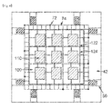
- the apparatus for fixing a printed matter 100 may be mounted on a printed matter stage 42.
- the printed matter stage 42 means a support portion of the printed matter, on which the printed matter may be placed.
- the apparatus for fixing a printed matter may be attached to and detached from a printed matter stage, and thus is advantageous in that it is facilitated to simultaneously form a plurality of printing patterns in one printing by fixing a plurality of printed matters.
- a printed matter 40 may be fixed to an upper portion of the apparatus for fixing a printed matter 100, and a printed matter stage 42 may be provided at a lower portion of the apparatus for fixing a printed matter.
- the vacuum hole 122 and/or vacuum passage 124 may be disposed at a lower portion of the engraved portion 110, and one or two or more vacuum holes 122 and/or vacuum passages 124 may be provided at a lower portion of one engraved portion 110.
- the vacuum hole 122 and/or vacuum passage 124 may also be disposed at a portion in which the engraved portion 110 is not present in the apparatus for fixing a printed matter 100.
- FIGS. 2 and 3 illustrate the side structure of the vacuum hole 122 and the vacuum passage 124 disposed at a lower portion of the engraved portion 110 and a plan view thereof when observed from above.
- the surface may include a structure of the vacuum passage 124 composed of a groove. Intersection points having a lattice form of the structure of the vacuum passage 124 composed of a groove may have a structure of a hole 122.
- the shape and diameter of the hole, or the shape, width and depth of the groove of the structure of the passage are not particularly limited as long as the printed matter 40 may be fixed to the apparatus for fixing a printed matter 100 without being deformed by the vacuum hole 122 and the vacuum passage 124.
- the diameter of the vacuum hole 122 may be one to 15 times the thickness of the printed matter, but is not limited thereto.
- the width of the vacuum passage 124 may be one to 10 times the thickness of the printed matter, but is not limited thereto.
- vacuum refers to the state where pressure is lower than normal pressure (760 mmHg), and the degree of vacuum means a pressure of the remaining gas in a container under vacuum when compared to the state of vacuum with respect to normal pressure.
- the degree of vacuum of the vacuum adsorption is not particularly limited as long as the printed matter may be fixed to the apparatus for fixing a printed matter without being deformed by the vacuum hole 122 and the vacuum passage 124.
- the degree of vacuum of the vacuum adsorption may be 5% or less of normal pressure.
- the degree of vacuum of the vacuum hole 122 and vacuum passage 124 may be 50 mmHg or less.
- the lower limit of the degree of vacuum of the vacuum hole 122 and vacuum passage 124 is not particularly limited as long as the printed matter is not deformed by the vacuum hole 122 and vacuum passage 124 according to the type and thickness of the printed matter used.
- FIG. 4 illustrates that the apparatus for fixing a printed matter 100 according to an exemplary embodiment of the present application is mounted on a printed matter stage 42 with a plan view when observed from above
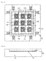
- FIG. 5 illustrates that a printed matter 40 is fixed to the apparatus for fixing a printed matter 100 according to an exemplary embodiment of the present application and thus is mounted on a printed matter stage 42 with a plan view when observed from above.
- the engraved portion 110 is disposed at an upper portion of the apparatus for fixing a printed matter 100, and may be formed such that the printed matter may be arranged and installed.
- the engraved portion 110 may include a projection or groove for fixing a printed matter at the inner side thereof.
- the shape of the projection or groove is not particularly limited as long as the shape has a structure capable of facilitating the fixation of the printed matter 40.
- the shape of the cross-section of the projection or groove may be a circular, triangular, quadrangular, or trapezoidal shape.
- the depth of the engraved portion 110 may be equal to or smaller than the thickness of the printed matter 40.
- the depth of the engraved portion 110 is larger than the thickness of the printed matter 40, it is difficult to vacuum-adsorb the apparatus for fixing a printed matter 100 to the printed matter stage 42 because there is no place where the vacuum hole 122 and the vacuum passage 124 are formed.
- the depth deviation of the engraved portion 110 may be 100 ⁇ m or less. Specifically, the deviation between depths of a plurality of engraved portions 110 may be 100 ⁇ m or less. When the depth deviation of the engraved portion 110 is 100 ⁇ m or less, the precision of the level difference between printed matters is improved when the printed matter 40 is fixed, and thus, the precision of the printing pattern 41 printed on the printed matter 40 is also good.
- the printed matter stage 42 may further include a position control portion 50 for aligning the printed matter.
- the position control portion of the printed matter stage may control a position on a plane.
- the position control portion of the printed matter stage may have a configuration in which a microscopic position of the printed matter stage is controlled to three positions, that is, a position in the x direction, a position in the y direction, and a position in the theta (0) direction.
- the x direction is defined as any one direction on a plate surface of the printed matter stage, for example, as a transverse direction of the printed matter stage
- y means a direction vertical to the x direction on the plate surface of the printed matter stage, for example, a longitudinal direction of the printed matter stage
- theta (0) direction means an angle on the plate surface of the printed matter stage.
- the configuration is not particularly limited as long as the position on the plane of the printed matter stage may be controlled.
- the printed matter stage 42 may include a vacuum suction portion 70 corresponding to the vacuum hole 122 and vacuum passage 124 of the engraved portion 110.
- the structure of the vacuum passage 124 of the apparatus for fixing a printed matter 100 corresponds to the structure of the vacuum passage 74 of the printed matter stage 42.
- the structure of the vacuum hole 122 of the apparatus for fixing a printed matter 100 may be connected under vacuum to the structure of the vacuum hole 72 of the printed matter stage 42 in correspondence therewith, and fixed thereto.
- the printed matter stage 42 may be provided with a porous plate 62 or a porous film 64.
- the porous plate and the porous film may prevent the printed matter from being damaged while having a porous structure capable of achieving vacuum suction by the vacuum suction portion, the structure, form, material and the like thereof are not limited.
- the porous plate 62 and the porous film 64 may be selected by those skilled in the art in consideration of the type and the like of the printed matter.
- the porous plate 62 or the porous film 64 may have an average pore size of 100 ⁇ m or less, specifically, 30 ⁇ m or less.
- the lower limit of the average pore size of the porous plate 62 or the porous film 64 is not particularly limited as long as air may pass through the porous plate 62 or the porous film 64, and may be, for example, 10 nm or more.
- the porosity may be 10% or more.
- FIGS. 6 and 7 illustrate a side view of a printed matter stage 42 in a printing device according to an exemplary embodiment of the present application.
- the vacuum suction portion 70 is necessary for alignment, which is necessary for controlling the position of a precise pattern and performing a superimposed printing.
- the vacuum suction portion 70 may include the structure of a vacuum hole 72 or the structure of a vacuum passage 74, which is capable of achieving vacuum suction.
- FIGS. 8 and 9 illustrate a side view of a vacuum suction portion 70 of the printed matter stage 42 of the printing device according to an exemplary embodiment of the present application.
- FIGS. 10 and 11 illustrate a plan view of the printed matter stage of the printing device according to an exemplary embodiment of the present application when observed from above.
- the apparatus for fixing a printed matter 100 When the apparatus for fixing a printed matter 100 according to an exemplary embodiment of the present application is used in a printing process, there is an advantage in terms of alignment of the printed matter and the printed matter stage 42. Since the printed matter is fixed to the apparatus for fixing a printed matter 100, it is easier to mount the printed matter on the printed matter stage 42, and it is easy to align the printed matter. Furthermore, since it is easy to align the printed matter, it is more efficient to form a microscopic and precise printing pattern.
- a plurality of printed matters 40 may be fixed to one apparatus for fixing a printed matter 100, printing patterns may be formed on a plurality of printed matters 40 in one printing. Therefore, there is an effect that process efficiency is excellent and the process cost is reduced.
- Another exemplary embodiment of the present application provides a printing device including the apparatus for fixing a printed matter 100.
- the printing device may be a reverse offset printing device.
- the printing device may further include a cliché 31 including a pattern portion corresponding to the pattern position of the printed matter 40 which may be fixed on the apparatus for fixing a printed matter 100; and a cliché stage 30.
- the cliché stage means a cliché support portion on which the cliché 31 may be mounted.
- the cliché 31 may include two or more alignment marks.
- the form of the alignment mark is transferred on the printed matter by a printing composition.
- the alignment mark is regardless of the size or form as long as the position of the cliché 31 may be sensed such that the position of the cliché 31 may be controlled according to the degree of alignment.
- the alignment mark formed on the cliché 31 may be engraved or embossed based on the form to be transferred on the printed matter 40.
- the alignment mark is for indicating the position
- the size or form of the alignment mark is not particularly limited as long as the alignment mark may be sensed by a means for sensing the alignment mark, for example, a camera. Even when an opaque material is used as a printed matter by forming the alignment mark on the cliché substrate as described above, it is possible to implement an alignment with high accuracy.
- the cliché stage 30 may additionally include an alignment camera for recognizing an alignment mark on the cliché 31 and a position control portion of the cliché stage 30.
- the position control portion of the cliché stage 30 may control a position on a plane.
- the position control portion of the cliché stage 30 may have a configuration in which a microscopic position of the cliché stage 30 is controlled to three positions, that is, a position in the x direction, a position in the y direction, and a position in theta ( ⁇ ) direction.
- the x direction is defined as any one direction on a plate surface of the cliché stage 30, for example, as a transverse direction of the cliché stage 30, y means a direction vertical to the x direction on the plate surface of the cliché stage 30, for example, a longitudinal direction of the cliché stage 30, and theta ( ⁇ ) direction means an angle on the plate surface of the cliché stage 30.
- the configuration is not particularly limited as long as the position on the plane of the cliché stage 30 may be controlled.
- FIG. 12 illustrates an example of the position controlling method of the cliché stage 30.
- the position control portion of the cliché stage 30 includes A, B, C, and D.
- A, B, C, and D are each provided in the vicinity of each vertex of the cliché stage 30 and move in an arrow direction indicated as the red color, thereby controlling the position of the cliché stage 30.
- the printing device may further include a printed matter stage 42 on which the apparatus for fixing a printed matter 100 may be mounted.
- the description on the printed matter stage 42 is the same as described above.
- the printing device may be used for printing various patterns necessary for various electronic devices on a printed matter.
- the printed matter may also be used as a flexible substrate in an electronic device, for example, a touch panel, various displays, and the like, and may be used as a film member in addition to the flexible substrate.
- the printed matter may be used for printing a conductive pattern, an insulating pattern, a resist pattern, a color pattern, a black matrix pattern, and the like.
- the printed matter according to an exemplary embodiment of the present application may have a printing pattern having a line width and a pitch, which are necessary according to the use thereof.
- the printed matter may have a printing pattern with a line width of 120 ⁇ m or less, specifically, from 1 ⁇ m to 120 ⁇ m.
- the printing film may include a printing pattern with a line width from 1 ⁇ m to 5 ⁇ m, or from 15 ⁇ m to 100 ⁇ m.
- An exemplary embodiment of the present application provides a printing method using the apparatus for fixing a printed matter.
- the printing method may include: fixing a printed matter to an engraved portion of the apparatus for fixing a printed matter; mounting the apparatus for fixing a printed matter on a printed matter stage; vacuum adsorbing the apparatus for fixing a printed matter and the printed matter stage; and printing a pattern on the printed matter.
- the sequence of the step of fixing the printed matter to the engraved portion of the apparatus for fixing a printed matter and the step of mounting the apparatus for fixing a printed matter on the printed matter stage is not particularly limited.
- the printing method may fix a printed matter to an engraved portion of an apparatus for fixing a printed matter, and then mount the apparatus for fixing a printed matter on a printed matter stage, or may mount the apparatus for fixing a printed matter on the printed matter stage, and then fix the printed matter to the engraved portion of the apparatus for fixing a printed matter.
- the printing method may be a reverse offset printing method.
- the printing method according to an exemplary embodiment of the present application may further include aligning the apparatus for fixing a printed matter and the printed matter stage after mounting the apparatus for fixing a printed matter on the printed matter stage.
- the sequence thereof is not particularly limited.
- the apparatus for fixing a printed matter and the printed matter stage may be aligned, and then the apparatus for fixing a printed matter and the printed matter stage may be vacuum adsorbed, or the apparatus for fixing a printed matter and the printed matter stage may be vacuum adsorbed, and then the apparatus for fixing a printed matter and the printed matter stage may be aligned.
- a region to be printed of the printed matter may be aligned using a position control portion provided on the printed matter stage.
- the precision of the pattern printed by the printing method according to an exemplary embodiment of the present application corresponds to the precision of the alignment.
- the pattern printed by the printing method according to an exemplary embodiment of the present application may have a precision within an error range of 1 mm or less, specifically, 0.5 mm or less.
- the printing step in an exemplary embodiment of the present application may include: coating a printing matter on a printing roll; forming a printing matter pattern on a printing roll by bringing the printing roll on which the printing matter is coated in contact with a cliché; and transferring the printing matter pattern coated on the printing roll on the printed matter.
Landscapes
- Engineering & Computer Science (AREA)
- Mechanical Engineering (AREA)
- Printing Methods (AREA)
- Manufacturing Of Printed Wiring (AREA)
- Screen Printers (AREA)
Abstract
Description
- The present application relates to an apparatus for fixing a printed matter, a printing device including the same and a printing method including the same. This application claims priority to and the benefit of Korean Patent Application No.
10-2012-0074993 - Recently, patterns of various functional materials are required for an electronic device. For example, a conductive pattern for an electrode, a black matrix pattern and a color pattern for a color filter, an insulating pattern and a resist pattern for a thin film transistor (TFT), and the like are required.
- The patterns may be formed by a photolithography method, and the like, but a pattern forming method using a printing method has been attempted in consideration of process costs or efficiency.
- In the printing method, there are various problems to be solved in advance, such as an alignment problem for forming a precise pattern at an exact position of a printed matter, requirements for increasing process efficiency, and requirements for reducing costs.
- The present application has been made in an effort to provide a printing method and a printing device, which may improve process efficiency by forming a precise electronic material pattern, or forming a pattern on a plurality of printed matters in one printing.
- An exemplary embodiment of the present application provides an apparatus for fixing a printed matter including a plurality of engraved portions which may fix a plurality of printed matters, and at least one vacuum hole or vacuum passage provided at a lower portion of the engraved portion.
- Another exemplary embodiment of the present application provides a printing device including the apparatus for fixing a printed matter.
- Still another exemplary embodiment of the present application provides a printing method using the apparatus for fixing a printed matter.
- The apparatus for fixing a printed matter according to an exemplary embodiment of the present application may efficiently fix and align the printed matter when mounting the printed matter on a printed matter stage, and may fix one or more printed matters on one apparatus for fixing a printed matter, and thus is advantageous in that patterns may be formed on a plurality of printed matters in one printing. Therefore, there is an advantage in that the precision of the printing pattern is enhanced, the process efficiency is improved, and process costs are reduced.
-
-
FIG. 1 illustrates a reverse offset printing process. -
FIG. 2 illustrates a side view of an apparatus for fixing a printed matter according to an exemplary embodiment of the present application. -
FIG. 3 illustrates a plan view of the apparatus for fixing a printed matter according to an exemplary embodiment of the present application when observed from above. -
FIG. 4 illustrates that the apparatus for fixing a printed matter according to an exemplary embodiment of the present application is mounted on a printed matter stage with a plan view when observed from above. -
FIG. 5 illustrates that a printed matter is fixed to the apparatus for fixing a printed matter according to an exemplary embodiment of the present application and thus is mounted on a printed matter stage with a plan view when observed from above. -
FIGS. 6 and7 illustrate a side view of a printed matter stage of a printing device according to an exemplary embodiment of the present application. -
FIGS. 8 and 9 illustrate a side view of a vacuum suction portion of the printed matter stage of the printing device according to an exemplary embodiment of the present application. -
FIGS. 10 and11 illustrate a plan view of the printed matter stage of the printing device according to an exemplary embodiment of the present application. -
FIG. 12 illustrates an example of operating a position control portion of a stage for mounting a cliché according to an exemplary embodiment of a printing device according to the present application. - The advantages and features of the present application, and methods of accomplishing the advantages and features will become obvious with reference to exemplary embodiments to be described below in detail along with the accompanying drawings. However, the present application is not limited to the exemplary embodiments to be disclosed below, but will be implemented in various forms different from each other. The exemplary embodiments are merely intended to make the disclosure of the present application complete and to completely notify the person with ordinary skill to which the present application pertains of the scope of the invention, and the present application is only defined by the scope of the claims. The size and relative size of the constituent elements marked in the drawings may be exaggerated for clarity of description. Hereinafter, the description made with reference to the accompanying drawings will be provided for illustrative purposes only, and the scope of the present application is not limited thereby.
- Unless otherwise defined, all terms including technical and scientific terms used in the present specification may be used as the meaning which may be commonly understood by the person with ordinary skill in the art to which the present application pertains. Terms defined in commonly used dictionaries should not be interpreted in an idealized or excessive sense unless clearly and particularly defined.
- Hereinafter, the present application will be described in detail.
- An exemplary embodiment of the present application provides an apparatus for fixing a printed
matter 100 used in a printing device. The apparatus for fixing a printedmatter 100 may include a plurality of engravedportions 110 which may fix a plurality of printed matters; and at least onevacuum hole 122 and/or at least onevacuum passage 124 provided at a lower portion of the engravedportion 110. The apparatus for fixing a printedmatter 100 may fix a printedmatter 40 at each engravedportion 110. - Specifically, the apparatus for fixing a printed
matter 100 may include two or more engravedportions 110 which may fix two or more printed matters; and at least onevacuum hole 122 and/or a least onevacuum passage 124 provided at a lower portion of the engravedportion 110. Thus, one apparatus for fixing a printed matter may fix two or more printed matters simultaneously, and thus is advantageous in that printing patterns may be formed on two or more printed matters in one printing. - Alternatively, the apparatus for fixing a printed
matter 100 may include four or more engravedportions 110 which may fix four or more printed matters; and at least onevacuum hole 122 and/or at least onevacuum passage 124 provided at a lower portion of the engravedportion 110. Thus, one apparatus for fixing a printed matter may fix four or more printed matters simultaneously, and thus is advantageous in that printing patterns may be formed on four or more printed matters in one printing. - Alternatively, the apparatus for fixing a printed
matter 100 may include six or more engravedportions 110 which may fix six or more printed matters; and at least onevacuum hole 122 and/or at least onevacuum passage 124 provided at a lower portion of the engravedportion 110. Thus, one apparatus for fixing a printed matter may fix six or more printed matters simultaneously, and thus is advantageous in that printing patterns may be formed on six or more printed matters in one printing. - Alternatively, the apparatus for fixing a printed
matter 100 may include eight or more engravedportions 110 which may fix eight or more printed matters; and at least onevacuum hole 122 and/or at least onevacuum passage 124 provided at a lower portion of the engravedportion 110. Thus, one apparatus for fixing a printed matter may fix eight or more printed matters simultaneously, and thus is advantageous in that printing patterns may be formed on eight or more printed matters in one printing. - Alternatively, the apparatus for fixing a printed
matter 100 may include nine or more engravedportions 110 which may fix nine or more printed matters; and at least onevacuum hole 122 and/or at least onevacuum passage 124 provided at a lower portion of the engravedportion 110. Thus, one apparatus for fixing a printed matter may fix nine or more printed matters simultaneously, and thus is advantageous in that printing patterns may be formed on nine or more printed matters in one printing. - One or two or
more vacuum holes 122 and/or one or two ormore vacuum passages 124 may be provided at a lower portion of each engravedportion 110. -
FIG. 2 illustrates a side view of the apparatus for fixing a printed matter according to an exemplary embodiment of the present application, andFIG. 3 illustrates a plan view of the apparatus when observed from above. - In the present specification, the printed
matter 40 means a printing object on which a printing pattern is transferred or an object to be printed, and may be, for example, a substrate. Further, the substrate may be glass or plastic. - A printing process by which the apparatus for fixing a printed matter according to an exemplary embodiment of the present application is used may be a reverse offset printing process.
FIG. 1 illustrates an exemplary embodiment of the reverse offset printing process. According toFIG. 1 , a printing roll includes aprinting roll stage 20 and ablanket 21 provided to cover the surface of the printing roll stage. Aprinting matter 22 is coated on ablanket 21 of the printing roll using acoating portion 10. Subsequently, aprinting matter pattern 41 is formed on theblanket 21 by removing a part of aprinting matter pattern 32 from theblanket 21 of the printing roll by bringing theblanket 21 of the printing roll in contact with acliché 31 provided on acliché stage 30. Subsequently, theprinting matter pattern 41 is transferred on the printedmatter 40 by bringing theblanket 21 of the printing roll in contact with the printedmatter 40. - In an exemplary embodiment of the present application, the apparatus for fixing a printed
matter 100 may be mounted on a printedmatter stage 42. In the present specification, the printedmatter stage 42 means a support portion of the printed matter, on which the printed matter may be placed. - The apparatus for fixing a printed matter according to an exemplary embodiment of the present application may be attached to and detached from a printed matter stage, and thus is advantageous in that it is facilitated to simultaneously form a plurality of printing patterns in one printing by fixing a plurality of printed matters.
- In an exemplary embodiment of the present application, a printed
matter 40 may be fixed to an upper portion of the apparatus for fixing a printedmatter 100, and a printedmatter stage 42 may be provided at a lower portion of the apparatus for fixing a printed matter. - In an exemplary embodiment of the present application, the
vacuum hole 122 and/orvacuum passage 124 may be disposed at a lower portion of the engravedportion 110, and one or two ormore vacuum holes 122 and/orvacuum passages 124 may be provided at a lower portion of one engravedportion 110. Alternatively, thevacuum hole 122 and/orvacuum passage 124 may also be disposed at a portion in which the engravedportion 110 is not present in the apparatus for fixing a printedmatter 100. -
FIGS. 2 and3 illustrate the side structure of thevacuum hole 122 and thevacuum passage 124 disposed at a lower portion of the engravedportion 110 and a plan view thereof when observed from above. In order to increase efficiency of vacuum adsorption by the structure of thevacuum hole 122, the surface may include a structure of thevacuum passage 124 composed of a groove. Intersection points having a lattice form of the structure of thevacuum passage 124 composed of a groove may have a structure of ahole 122. The shape and diameter of the hole, or the shape, width and depth of the groove of the structure of the passage are not particularly limited as long as the printedmatter 40 may be fixed to the apparatus for fixing a printedmatter 100 without being deformed by thevacuum hole 122 and thevacuum passage 124. - For example, the diameter of the
vacuum hole 122 may be one to 15 times the thickness of the printed matter, but is not limited thereto. - For example, the width of the
vacuum passage 124 may be one to 10 times the thickness of the printed matter, but is not limited thereto. - In order to enhance the adsorption power thereof, the smaller a degree of vacuum of the vacuum adsorption is than normal pressure, the better the degree of vacuum is. At this time, vacuum refers to the state where pressure is lower than normal pressure (760 mmHg), and the degree of vacuum means a pressure of the remaining gas in a container under vacuum when compared to the state of vacuum with respect to normal pressure.
- The degree of vacuum of the vacuum adsorption is not particularly limited as long as the printed matter may be fixed to the apparatus for fixing a printed matter without being deformed by the
vacuum hole 122 and thevacuum passage 124. - For example, the degree of vacuum of the vacuum adsorption may be 5% or less of normal pressure. The degree of vacuum of the
vacuum hole 122 andvacuum passage 124 may be 50 mmHg or less. - The lower limit of the degree of vacuum of the
vacuum hole 122 andvacuum passage 124 is not particularly limited as long as the printed matter is not deformed by thevacuum hole 122 andvacuum passage 124 according to the type and thickness of the printed matter used. -
FIG. 4 illustrates that the apparatus for fixing a printedmatter 100 according to an exemplary embodiment of the present application is mounted on a printedmatter stage 42 with a plan view when observed from above, andFIG. 5 illustrates that a printedmatter 40 is fixed to the apparatus for fixing a printedmatter 100 according to an exemplary embodiment of the present application and thus is mounted on a printedmatter stage 42 with a plan view when observed from above. - In an exemplary embodiment of the present application, the engraved
portion 110 is disposed at an upper portion of the apparatus for fixing a printedmatter 100, and may be formed such that the printed matter may be arranged and installed. The engravedportion 110 may include a projection or groove for fixing a printed matter at the inner side thereof. The shape of the projection or groove is not particularly limited as long as the shape has a structure capable of facilitating the fixation of the printedmatter 40. For example, the shape of the cross-section of the projection or groove may be a circular, triangular, quadrangular, or trapezoidal shape. - In an exemplary embodiment of the present application, the depth of the engraved
portion 110 may be equal to or smaller than the thickness of the printedmatter 40. When the depth of the engravedportion 110 is larger than the thickness of the printedmatter 40, it is difficult to vacuum-adsorb the apparatus for fixing a printedmatter 100 to the printedmatter stage 42 because there is no place where thevacuum hole 122 and thevacuum passage 124 are formed. - In an exemplary embodiment of the present application, the depth deviation of the engraved
portion 110 may be 100 µm or less. Specifically, the deviation between depths of a plurality of engravedportions 110 may be 100 µm or less. When the depth deviation of the engravedportion 110 is 100 µm or less, the precision of the level difference between printed matters is improved when the printedmatter 40 is fixed, and thus, the precision of theprinting pattern 41 printed on the printedmatter 40 is also good. - In an exemplary embodiment of the present application, the printed
matter stage 42 may further include aposition control portion 50 for aligning the printed matter. - In an exemplary embodiment of the present application, the position control portion of the printed matter stage may control a position on a plane. For example, the position control portion of the printed matter stage may have a configuration in which a microscopic position of the printed matter stage is controlled to three positions, that is, a position in the x direction, a position in the y direction, and a position in the theta (0) direction. Here, when the x direction is defined as any one direction on a plate surface of the printed matter stage, for example, as a transverse direction of the printed matter stage, y means a direction vertical to the x direction on the plate surface of the printed matter stage, for example, a longitudinal direction of the printed matter stage, and the theta (0) direction means an angle on the plate surface of the printed matter stage. As described above, the configuration is not particularly limited as long as the position on the plane of the printed matter stage may be controlled.
- In an exemplary embodiment of the present application, the printed
matter stage 42 may include avacuum suction portion 70 corresponding to thevacuum hole 122 andvacuum passage 124 of the engravedportion 110. The structure of thevacuum passage 124 of the apparatus for fixing a printedmatter 100 corresponds to the structure of thevacuum passage 74 of the printedmatter stage 42. In addition, the structure of thevacuum hole 122 of the apparatus for fixing a printedmatter 100 may be connected under vacuum to the structure of thevacuum hole 72 of the printedmatter stage 42 in correspondence therewith, and fixed thereto. - In an exemplary embodiment of the present application, the printed
matter stage 42 may be provided with aporous plate 62 or aporous film 64. As long as the porous plate and the porous film may prevent the printed matter from being damaged while having a porous structure capable of achieving vacuum suction by the vacuum suction portion, the structure, form, material and the like thereof are not limited. - The
porous plate 62 and theporous film 64 may be selected by those skilled in the art in consideration of the type and the like of the printed matter. For example, theporous plate 62 or theporous film 64 may have an average pore size of 100 µm or less, specifically, 30 µm or less. The lower limit of the average pore size of theporous plate 62 or theporous film 64 is not particularly limited as long as air may pass through theporous plate 62 or theporous film 64, and may be, for example, 10 nm or more. - The larger the porosity is, the better the
porous plate 62 or theporous film 64 is. Specifically, the porosity may be 10% or more. - In an exemplary embodiment of the present application, the
porous plate 62 or theporous film 64 may be provided at an upper portion of thevacuum suction portion 70.FIGS. 6 and7 illustrate a side view of a printedmatter stage 42 in a printing device according to an exemplary embodiment of the present application. - In an exemplary embodiment of the present application, the
vacuum suction portion 70 is necessary for alignment, which is necessary for controlling the position of a precise pattern and performing a superimposed printing. Thevacuum suction portion 70 may include the structure of avacuum hole 72 or the structure of avacuum passage 74, which is capable of achieving vacuum suction.FIGS. 8 and 9 illustrate a side view of avacuum suction portion 70 of the printedmatter stage 42 of the printing device according to an exemplary embodiment of the present application.FIGS. 10 and11 illustrate a plan view of the printed matter stage of the printing device according to an exemplary embodiment of the present application when observed from above. - The description on the structure of the
vacuum hole 72 orvacuum passage 74 of thevacuum suction portion 70 is the same as described in the vacuum adsorption portion. - When the apparatus for fixing a printed
matter 100 according to an exemplary embodiment of the present application is used in a printing process, there is an advantage in terms of alignment of the printed matter and the printedmatter stage 42. Since the printed matter is fixed to the apparatus for fixing a printedmatter 100, it is easier to mount the printed matter on the printedmatter stage 42, and it is easy to align the printed matter. Furthermore, since it is easy to align the printed matter, it is more efficient to form a microscopic and precise printing pattern. - Further, since a plurality of printed
matters 40 may be fixed to one apparatus for fixing a printedmatter 100, printing patterns may be formed on a plurality of printedmatters 40 in one printing. Therefore, there is an effect that process efficiency is excellent and the process cost is reduced. - Another exemplary embodiment of the present application provides a printing device including the apparatus for fixing a printed
matter 100. - The printing device may be a reverse offset printing device.
- In an exemplary embodiment of the present application, the printing device may further include a
cliché 31 including a pattern portion corresponding to the pattern position of the printedmatter 40 which may be fixed on the apparatus for fixing a printedmatter 100; and acliché stage 30. In the present specification, the cliché stage means a cliché support portion on which thecliché 31 may be mounted. - In an exemplary embodiment of the present application, the
cliché 31 may include two or more alignment marks. The form of the alignment mark is transferred on the printed matter by a printing composition. The alignment mark is regardless of the size or form as long as the position of thecliché 31 may be sensed such that the position of thecliché 31 may be controlled according to the degree of alignment. The alignment mark formed on thecliché 31 may be engraved or embossed based on the form to be transferred on the printedmatter 40. - When there are two or more alignment marks, it is possible to exactly catch the disposed position of the
cliché 31, and three or four or more alignment marks may also be included, if necessary. Since the alignment mark is for indicating the position, the size or form of the alignment mark is not particularly limited as long as the alignment mark may be sensed by a means for sensing the alignment mark, for example, a camera. Even when an opaque material is used as a printed matter by forming the alignment mark on the cliché substrate as described above, it is possible to implement an alignment with high accuracy. - In this case, the
cliché stage 30 may additionally include an alignment camera for recognizing an alignment mark on thecliché 31 and a position control portion of thecliché stage 30. The position control portion of thecliché stage 30 may control a position on a plane. For example, the position control portion of thecliché stage 30 may have a configuration in which a microscopic position of thecliché stage 30 is controlled to three positions, that is, a position in the x direction, a position in the y direction, and a position in the theta (θ) direction. Here, when the x direction is defined as any one direction on a plate surface of thecliché stage 30, for example, as a transverse direction of thecliché stage 30, y means a direction vertical to the x direction on the plate surface of thecliché stage 30, for example, a longitudinal direction of thecliché stage 30, and the theta (θ) direction means an angle on the plate surface of thecliché stage 30. As described above, the configuration is not particularly limited as long as the position on the plane of thecliché stage 30 may be controlled. -
FIG. 12 illustrates an example of the position controlling method of thecliché stage 30. The position control portion of thecliché stage 30 includes A, B, C, and D. A, B, C, and D are each provided in the vicinity of each vertex of thecliché stage 30 and move in an arrow direction indicated as the red color, thereby controlling the position of thecliché stage 30. - In an exemplary embodiment of the present application, the printing device may further include a printed
matter stage 42 on which the apparatus for fixing a printedmatter 100 may be mounted. The description on the printedmatter stage 42 is the same as described above. - The printing device according to an exemplary embodiment of the present application may be used for printing various patterns necessary for various electronic devices on a printed matter. The printed matter may also be used as a flexible substrate in an electronic device, for example, a touch panel, various displays, and the like, and may be used as a film member in addition to the flexible substrate. For example, the printed matter may be used for printing a conductive pattern, an insulating pattern, a resist pattern, a color pattern, a black matrix pattern, and the like.
- The printed matter according to an exemplary embodiment of the present application may have a printing pattern having a line width and a pitch, which are necessary according to the use thereof. For example, the printed matter may have a printing pattern with a line width of 120 µm or less, specifically, from 1 µm to 120 µm. As an example, the printing film may include a printing pattern with a line width from 1 µm to 5 µm, or from 15 µm to 100 µm.
- An exemplary embodiment of the present application provides a printing method using the apparatus for fixing a printed matter.
- The printing method according to an exemplary embodiment of the present application may include: fixing a printed matter to an engraved portion of the apparatus for fixing a printed matter; mounting the apparatus for fixing a printed matter on a printed matter stage; vacuum adsorbing the apparatus for fixing a printed matter and the printed matter stage; and printing a pattern on the printed matter.
- In the printing method according to an exemplary embodiment of the present application, the sequence of the step of fixing the printed matter to the engraved portion of the apparatus for fixing a printed matter and the step of mounting the apparatus for fixing a printed matter on the printed matter stage is not particularly limited.
- The printing method according to an exemplary embodiment of the present application may fix a printed matter to an engraved portion of an apparatus for fixing a printed matter, and then mount the apparatus for fixing a printed matter on a printed matter stage, or may mount the apparatus for fixing a printed matter on the printed matter stage, and then fix the printed matter to the engraved portion of the apparatus for fixing a printed matter.
- In an exemplary embodiment of the present application, the printing method may be a reverse offset printing method.
- The printing method according to an exemplary embodiment of the present application may further include aligning the apparatus for fixing a printed matter and the printed matter stage after mounting the apparatus for fixing a printed matter on the printed matter stage.
- In the printing method according to an exemplary embodiment of the present application, when aligning the apparatus for fixing a printed matter and the printed matter stage and vacuum adsorbing the apparatus for fixing a printed matter and the printed matter stage are all performed, the sequence thereof is not particularly limited.
- In an exemplary embodiment of the present application, the apparatus for fixing a printed matter and the printed matter stage may be aligned, and then the apparatus for fixing a printed matter and the printed matter stage may be vacuum adsorbed, or the apparatus for fixing a printed matter and the printed matter stage may be vacuum adsorbed, and then the apparatus for fixing a printed matter and the printed matter stage may be aligned.
- In an exemplary embodiment of the present application, in the aligning step, a region to be printed of the printed matter may be aligned using a position control portion provided on the printed matter stage.
- The precision of the pattern printed by the printing method according to an exemplary embodiment of the present application corresponds to the precision of the alignment. The pattern printed by the printing method according to an exemplary embodiment of the present application may have a precision within an error range of 1 mm or less, specifically, 0.5 mm or less.
- The printing step in an exemplary embodiment of the present application may include: coating a printing matter on a printing roll; forming a printing matter pattern on a printing roll by bringing the printing roll on which the printing matter is coated in contact with a cliché; and transferring the printing matter pattern coated on the printing roll on the printed matter.
- It is understood by a person with ordinary skill in the art to which the present application pertains that various applications and modifications may be made within the scope of the present application based on the contents.
- Although the specific part of the present application has been described in detail, it is obvious to those skilled in the art that such a specific description is just a preferred embodiment and the scope of the present application is not limited thereto. Thus, the substantial scope of the present application will be defined by the appended claims and equivalents thereto.
-
- 10:
- Coating portion
- 20:
- Printing roll stage
- 21:
- Blanket
- 22:
- Printing matter
- 30:
- Cliché stage
- 31:
- Cliché
- 32:
- Printing matter pattern
- 40:
- Printed matter
- 41:
- Printing matter pattern
- 42:
- Printed matter stage
- 50:
- Position control portion
- 62:
- Porous plate
- 64:
- Porous film
- 70:
- Vacuum suction portion
- 72:
- Vacuum hole
- 74:
- Vacuum passage
- 100:
- Apparatus for fixing a printed matter
- 110:
- Engraved portion
- 122:
- Vacuum hole
- 124:
- Vacuum passage
Claims (26)
- An apparatus for fixing a printed matter comprising:a plurality of engraved portions which are capable of fixing a plurality of printed matters; andat least one vacuum hole or vacuum passage provided at a lower portion of the engraved portion.
- The apparatus for fixing a printed matter of claim 1, wherein the apparatus for fixing a printed matter is capable of being mounted on a printed matter stage.
- The apparatus for fixing a printed matter of claim 1, wherein four or more of the engraved portion are present.
- The apparatus for fixing a printed matter of claim 1, wherein the engraved portion is disposed at an upper portion of the apparatus for fixing a printed matter, and is formed such that the printed matter is arranged and installed.
- The apparatus for fixing a printed matter of claim 1, wherein the engraved portion includes a projection or groove for fixing a printed matter at the inner side thereof.
- The apparatus for fixing a printed matter of claim 1, wherein a depth of the engraved portion is equal to or smaller than a thickness of the printed matter.
- The apparatus for fixing a printed matter of claim 1, wherein a depth deviation of the engraved portion is 100 µm or less.
- The apparatus for fixing a printed matter of claim 2, wherein the printed matter stage comprises a vacuum suction portion corresponding to a vacuum hole or a vacuum passage provided at a lower portion of the engraved portion.
- The apparatus for fixing a printed matter of claim 1, wherein the printed matter is a substrate.
- The apparatus for fixing a printed matter of claim 9, wherein the substrate is glass or plastic.
- The apparatus for fixing a printed matter of claim 1, wherein the apparatus for fixing a printed matter is for reverse offset printing.
- A printing device comprising the apparatus for fixing a printed matter of any one of claims 1 to 11.
- The printing device of claim 12, wherein the printing device is a reverse offset printing device.
- The printing device of claim 12, further comprising:a printed matter stage on which the apparatus for fixing a printed matter is capable of being fixed.
- The printing device of claim 14, further comprising:a cliché comprising a pattern portion corresponding to a pattern position of a printed matter which is capable of being fixed on the apparatus for fixing a printed matter; anda cliché stage.
- The printing device of claim 14, wherein the printed matter stage comprises a vacuum suction portion corresponding to a vacuum hole or a vacuum passage provided in the apparatus for fixing a printed matter.
- The printing device of claim 16, wherein the vacuum suction portion of the printed matter stage comprises a hole structure or a passage structure.
- The printing device of claim 16, wherein the printed matter stage is provided with a porous plate or a porous film on the vacuum suction portion.
- The printing device of claim 14, wherein the printed matter stage further comprises a position control portion for aligning the printed matter.
- A printing method using the apparatus for fixing a printed matter of any one of claims 1 to 11.
- The printing method of claim 20, comprising:fixing a printed matter to an engraved portion of the apparatus for fixing a printed matter;mounting the apparatus for fixing a printed matter on a printed matter stage;vacuum adsorbing the apparatus for fixing a printed matter and the printed matter stage; andprinting a pattern on the printed matter.
- The printing method of claim 21, wherein the printing method is a reverse offset printing method.
- The printing method of claim 21, further comprising:aligning the apparatus for fixing a printed matter and the printed matter stage after mounting the apparatus for fixing a printed matter on the printed matter stage.
- The printing method of claim 23, wherein in the aligning, a region to be printed of the printed matter is aligned using a position control portion provided on the printed matter stage.
- The printing method of claim 23, wherein a precision of the pattern printed by the printing method corresponds to a precision of the alignment.
- The printing method of claim 21, wherein the printing comprises:coating a printing matter on a printing roll;forming a printing matter pattern on a printing roll by bringing the printing roll on which the printing matter is coated in contact with a cliché; andtransferring the printing matter pattern coated on the printing roll on the printed matter.
Applications Claiming Priority (2)
| Application Number | Priority Date | Filing Date | Title |
|---|---|---|---|
| KR20120074993 | 2012-07-10 | ||
| PCT/KR2013/006016 WO2014010887A1 (en) | 2012-07-10 | 2013-07-05 | Printed material fixing piece, printing device, and printing method |
Publications (2)
| Publication Number | Publication Date |
|---|---|
| EP2874179A1 true EP2874179A1 (en) | 2015-05-20 |
| EP2874179A4 EP2874179A4 (en) | 2016-05-11 |
Family
ID=49916277
Family Applications (1)
| Application Number | Title | Priority Date | Filing Date |
|---|---|---|---|
| EP13817283.8A Withdrawn EP2874179A4 (en) | 2012-07-10 | 2013-07-05 | PRINTED MATERIAL FIXING PART, PRINTING DEVICE, AND PRINTING METHOD |
Country Status (7)
| Country | Link |
|---|---|
| US (1) | US9315015B2 (en) |
| EP (1) | EP2874179A4 (en) |
| JP (1) | JP5843246B2 (en) |
| KR (2) | KR20140008250A (en) |
| CN (1) | CN104040688B (en) |
| TW (1) | TWI538586B (en) |
| WO (1) | WO2014010887A1 (en) |
Families Citing this family (7)
| Publication number | Priority date | Publication date | Assignee | Title |
|---|---|---|---|---|
| JP3052143B2 (en) | 1989-11-06 | 2000-06-12 | 大日本インキ化学工業株式会社 | Natural stone-like artificial marble and method for producing the same |
| JP3235579B2 (en) | 1998-12-18 | 2001-12-04 | 大日本インキ化学工業株式会社 | Natural stone-like artificial marble and method for producing the same |
| CN104377157B (en) | 2014-10-22 | 2017-05-10 | 京东方科技集团股份有限公司 | Vacuum absorption system and method of packaging mother board and packaging device |
| KR101684238B1 (en) * | 2015-03-25 | 2016-12-20 | 한국기계연구원 | Printing correction system using a flexible cliche and a printing method using the same |
| KR101688615B1 (en) * | 2015-05-07 | 2017-01-02 | 한국기계연구원 | Printing correction system using flexible and hard cliches and a printing method using the same |
| JP5994071B1 (en) * | 2015-06-25 | 2016-09-21 | 株式会社三宏 | Flat file printing apparatus and printing method |
| CN113225922A (en) * | 2021-05-31 | 2021-08-06 | 深圳市百柔新材料技术有限公司 | Slurry vacuum hole plugging device and hole plugging method |
Family Cites Families (26)
| Publication number | Priority date | Publication date | Assignee | Title |
|---|---|---|---|---|
| DE3228152C2 (en) * | 1982-07-28 | 1984-12-06 | Bernd 7141 Schwieberdingen Berberich | Cliché holder for pad printing machines |
| US4727806A (en) * | 1985-08-26 | 1988-03-01 | Wilson Engraving Company, Inc. | Pin register system for flexographic printing plates |
| US4743324A (en) * | 1986-08-20 | 1988-05-10 | W. R. Grace & Co., Cryovac Div. | Printing plate mounter |
| JP2693720B2 (en) * | 1994-05-25 | 1997-12-24 | シーケーディ株式会社 | Method for adsorbing an object to be adsorbed on a vacuum chuck |
| KR100292031B1 (en) * | 1998-07-14 | 2001-06-01 | 윤종용 | Method for washing a printing plate for making a alignment film and apparatus for washing the printing plate for applicating the same |
| JP2004087561A (en) * | 2002-08-23 | 2004-03-18 | Fuji Mach Mfg Co Ltd | Machine for aggregating manufacturing processes of multilayer board |
| JP2005243896A (en) * | 2004-02-26 | 2005-09-08 | Dainippon Printing Co Ltd | Processing equipment |
| JP4289184B2 (en) * | 2004-03-15 | 2009-07-01 | パナソニック株式会社 | Substrate transport jig, mounting method and mounting system using the same |
| KR101085141B1 (en) * | 2004-12-17 | 2011-11-21 | 엘지디스플레이 주식회사 | Pattern forming method with step, thin film transistor forming method and liquid crystal display device manufacturing method using the same |
| JP5180820B2 (en) | 2005-05-03 | 2013-04-10 | コーニンクレッカ フィリップス エレクトロニクス エヌ ヴィ | Method and apparatus for transferring a pattern from a stamp to a substrate |
| KR101319273B1 (en) * | 2005-12-29 | 2013-10-16 | 엘지디스플레이 주식회사 | Printing plate stage, Printing system and Method of manufacturing of Liquid Crystal Display Device using the same |
| JP4853078B2 (en) * | 2006-03-30 | 2012-01-11 | 凸版印刷株式会社 | Printing method, electrode pattern forming method, and thin film transistor forming method |
| KR20070120674A (en) * | 2006-06-20 | 2007-12-26 | 삼성전자주식회사 | Pattern transfer device |
| JP2008085275A (en) * | 2006-09-29 | 2008-04-10 | Joyo Kogaku Kk | Method and device for alignment |
| JP2008246829A (en) | 2007-03-30 | 2008-10-16 | Nec Lcd Technologies Ltd | Printing plate for letterpress reverse offset printing, method for manufacturing the same, display device, and method for manufacturing substrate for display device |
| GB2452320B (en) * | 2007-09-03 | 2012-04-11 | Dek Int Gmbh | Workpiece processing system and method |
| KR100922574B1 (en) | 2007-11-30 | 2009-10-21 | 한국전자통신연구원 | Thin substrate fixing device and nanopattern manufacturing method of thin substrate using the same |
| KR20100009919A (en) * | 2008-07-21 | 2010-01-29 | 엘지디스플레이 주식회사 | Method of forming cliche for resist pattern-printing apparatus |
| JP5305507B2 (en) * | 2008-08-27 | 2013-10-02 | 富士機械製造株式会社 | Substrate positioning device and substrate positioning method for screen printing machine |
| US8281715B2 (en) * | 2009-02-16 | 2012-10-09 | Vistaprint Technologies Limited | Printer pallet assembly for use in printing multiple articles of manufacture |
| JP2010208129A (en) * | 2009-03-10 | 2010-09-24 | Panasonic Corp | Screen printing device and screen plate |
| KR101430998B1 (en) * | 2010-08-10 | 2014-08-19 | 주식회사 엘지화학 | Roll printing apparatus comprising a softness porosity sheet and method of printing reverse offset using the same |
| KR20120028579A (en) * | 2010-09-15 | 2012-03-23 | 엘지디스플레이 주식회사 | Printing plate and fabricating method thereof |
| KR101263253B1 (en) * | 2010-11-24 | 2013-05-10 | 삼성전자주식회사 | roll printing device |
| JP5965133B2 (en) * | 2011-11-17 | 2016-08-03 | リンテック株式会社 | Light irradiation apparatus and light irradiation method |
| JP6027794B2 (en) * | 2012-07-04 | 2016-11-16 | ヤマハ発動機株式会社 | Transfer jig |
-
2013
- 2013-07-05 US US14/365,029 patent/US9315015B2/en active Active
- 2013-07-05 WO PCT/KR2013/006016 patent/WO2014010887A1/en not_active Ceased
- 2013-07-05 CN CN201380005098.3A patent/CN104040688B/en active Active
- 2013-07-05 JP JP2014548702A patent/JP5843246B2/en active Active
- 2013-07-05 KR KR1020130079255A patent/KR20140008250A/en not_active Ceased
- 2013-07-05 EP EP13817283.8A patent/EP2874179A4/en not_active Withdrawn
- 2013-07-09 TW TW102124496A patent/TWI538586B/en active
-
2015
- 2015-02-17 KR KR20150024097A patent/KR20150034700A/en not_active Ceased
Also Published As
| Publication number | Publication date |
|---|---|
| TWI538586B (en) | 2016-06-11 |
| TW201424490A (en) | 2014-06-16 |
| CN104040688B (en) | 2018-04-03 |
| US20140338551A1 (en) | 2014-11-20 |
| KR20150034700A (en) | 2015-04-03 |
| EP2874179A4 (en) | 2016-05-11 |
| JP5843246B2 (en) | 2016-01-13 |
| KR20140008250A (en) | 2014-01-21 |
| US9315015B2 (en) | 2016-04-19 |
| JP2015507558A (en) | 2015-03-12 |
| WO2014010887A1 (en) | 2014-01-16 |
| CN104040688A (en) | 2014-09-10 |
Similar Documents
| Publication | Publication Date | Title |
|---|---|---|
| US9315015B2 (en) | Printed material fixing piece, printing device, and printing method | |
| TWI503233B (en) | Screen printing method | |
| TWI541719B (en) | Method for forming bezel pattern of display panel | |
| CN103935122B (en) | Printing equipment | |
| WO2009108771A2 (en) | Methods of patterning a conductor on a substrate | |
| CN103314428A (en) | Printing device and printing method | |
| US20150246523A1 (en) | Roll printing machine and method of roll printing using same | |
| CN105527800B (en) | A kind of exposure method, exposure device and color membrane substrates | |
| TWI314670B (en) | Apparatus for forming fine pattern on substrate | |
| CN202857150U (en) | Auxiliary structure for aligning precision tests of LED (Light-Emitting Diode) light bar | |
| JP2012183793A (en) | Plate cylinder, printing device and printing method | |
| KR20160053909A (en) | Method for manufacturing touch panel | |
| CN106647188B (en) | Exposure system with double-sided alignment function | |
| KR101517697B1 (en) | Method for manufacturing film for transferring printed pattern, film for transferring printed pattern, apparatus for manufacturing the same and method for transferring pattern using the same | |
| CN106289591B (en) | Involute type flexible capacitive pressure sensor and preparation method thereof | |
| JP2012071506A (en) | Device and method for forming pattern | |
| JP2004017409A (en) | Letterpress and pattern forming method | |
| TW201442886A (en) | Systems and methods for detecting substrate alignment during a printing process | |
| US20230114015A1 (en) | Substrate treating apparatus and substrate treating method using the same | |
| KR20130075480A (en) | Both sided printing apparatus and method | |
| JP4353321B2 (en) | Electronic member manufacturing method and electronic member | |
| KR20110124020A (en) | Apparatus and method for exposing a printed circuit board using a drum peripheral surface, and method for manufacturing a printed circuit board using the method | |
| CN112885764A (en) | Transfer substrate, preparation method thereof and transfer device | |
| JP2004325965A (en) | Double-side exposure method | |
| TW201406556A (en) | Screen printer |
Legal Events
| Date | Code | Title | Description |
|---|---|---|---|
| PUAI | Public reference made under article 153(3) epc to a published international application that has entered the european phase |
Free format text: ORIGINAL CODE: 0009012 |
|
| 17P | Request for examination filed |
Effective date: 20140328 |
|
| AK | Designated contracting states |
Kind code of ref document: A1 Designated state(s): AL AT BE BG CH CY CZ DE DK EE ES FI FR GB GR HR HU IE IS IT LI LT LU LV MC MK MT NL NO PL PT RO RS SE SI SK SM TR |
|
| AX | Request for extension of the european patent |
Extension state: BA ME |
|
| DAX | Request for extension of the european patent (deleted) | ||
| RA4 | Supplementary search report drawn up and despatched (corrected) |
Effective date: 20160411 |
|
| RIC1 | Information provided on ipc code assigned before grant |
Ipc: H05K 3/00 20060101ALI20160401BHEP Ipc: B41F 3/34 20060101ALI20160401BHEP Ipc: B41F 3/51 20060101ALI20160401BHEP Ipc: B41F 3/20 20060101AFI20160401BHEP Ipc: B41M 1/06 20060101ALI20160401BHEP |
|
| 17Q | First examination report despatched |
Effective date: 20180823 |
|
| STAA | Information on the status of an ep patent application or granted ep patent |
Free format text: STATUS: THE APPLICATION IS DEEMED TO BE WITHDRAWN |
|
| 18D | Application deemed to be withdrawn |
Effective date: 20200902 |