EP2874176A1 - Focused ion beam system and method of making focal adjustment of ion beam - Google Patents
Focused ion beam system and method of making focal adjustment of ion beam Download PDFInfo
- Publication number
- EP2874176A1 EP2874176A1 EP20140191939 EP14191939A EP2874176A1 EP 2874176 A1 EP2874176 A1 EP 2874176A1 EP 20140191939 EP20140191939 EP 20140191939 EP 14191939 A EP14191939 A EP 14191939A EP 2874176 A1 EP2874176 A1 EP 2874176A1
- Authority
- EP
- European Patent Office
- Prior art keywords
- intensity
- ion beam
- sample
- objective lens
- secondary electrons
- Prior art date
- Legal status (The legal status is an assumption and is not a legal conclusion. Google has not performed a legal analysis and makes no representation as to the accuracy of the status listed.)
- Granted
Links
Images

Classifications
-
- H—ELECTRICITY
- H01—ELECTRIC ELEMENTS
- H01J—ELECTRIC DISCHARGE TUBES OR DISCHARGE LAMPS
- H01J37/00—Discharge tubes with provision for introducing objects or material to be exposed to the discharge, e.g. for the purpose of examination or processing thereof
- H01J37/30—Electron-beam or ion-beam tubes for localised treatment of objects
- H01J37/304—Controlling tubes by information coming from the objects or from the beam, e.g. correction signals
-
- H—ELECTRICITY
- H01—ELECTRIC ELEMENTS
- H01J—ELECTRIC DISCHARGE TUBES OR DISCHARGE LAMPS
- H01J37/00—Discharge tubes with provision for introducing objects or material to be exposed to the discharge, e.g. for the purpose of examination or processing thereof
- H01J37/02—Details
- H01J37/21—Means for adjusting the focus
-
- H—ELECTRICITY
- H01—ELECTRIC ELEMENTS
- H01J—ELECTRIC DISCHARGE TUBES OR DISCHARGE LAMPS
- H01J37/00—Discharge tubes with provision for introducing objects or material to be exposed to the discharge, e.g. for the purpose of examination or processing thereof
- H01J37/26—Electron or ion microscopes; Electron or ion diffraction tubes
- H01J37/28—Electron or ion microscopes; Electron or ion diffraction tubes with scanning beams
-
- H—ELECTRICITY
- H01—ELECTRIC ELEMENTS
- H01J—ELECTRIC DISCHARGE TUBES OR DISCHARGE LAMPS
- H01J37/00—Discharge tubes with provision for introducing objects or material to be exposed to the discharge, e.g. for the purpose of examination or processing thereof
- H01J37/30—Electron-beam or ion-beam tubes for localised treatment of objects
- H01J37/3002—Details
- H01J37/3005—Observing the objects or the point of impact on the object
-
- H—ELECTRICITY
- H01—ELECTRIC ELEMENTS
- H01J—ELECTRIC DISCHARGE TUBES OR DISCHARGE LAMPS
- H01J2237/00—Discharge tubes exposing object to beam, e.g. for analysis treatment, etching, imaging
- H01J2237/04—Means for controlling the discharge
- H01J2237/049—Focusing means
- H01J2237/0492—Lens systems
-
- H—ELECTRICITY
- H01—ELECTRIC ELEMENTS
- H01J—ELECTRIC DISCHARGE TUBES OR DISCHARGE LAMPS
- H01J2237/00—Discharge tubes exposing object to beam, e.g. for analysis treatment, etching, imaging
- H01J2237/06—Sources
- H01J2237/08—Ion sources
-
- H—ELECTRICITY
- H01—ELECTRIC ELEMENTS
- H01J—ELECTRIC DISCHARGE TUBES OR DISCHARGE LAMPS
- H01J2237/00—Discharge tubes exposing object to beam, e.g. for analysis treatment, etching, imaging
- H01J2237/10—Lenses
-
- H—ELECTRICITY
- H01—ELECTRIC ELEMENTS
- H01J—ELECTRIC DISCHARGE TUBES OR DISCHARGE LAMPS
- H01J2237/00—Discharge tubes exposing object to beam, e.g. for analysis treatment, etching, imaging
- H01J2237/21—Focus adjustment
-
- H—ELECTRICITY
- H01—ELECTRIC ELEMENTS
- H01J—ELECTRIC DISCHARGE TUBES OR DISCHARGE LAMPS
- H01J2237/00—Discharge tubes exposing object to beam, e.g. for analysis treatment, etching, imaging
- H01J2237/21—Focus adjustment
- H01J2237/216—Automatic focusing methods
-
- H—ELECTRICITY
- H01—ELECTRIC ELEMENTS
- H01J—ELECTRIC DISCHARGE TUBES OR DISCHARGE LAMPS
- H01J2237/00—Discharge tubes exposing object to beam, e.g. for analysis treatment, etching, imaging
- H01J2237/244—Detection characterized by the detecting means
- H01J2237/2448—Secondary particle detectors
-
- H—ELECTRICITY
- H01—ELECTRIC ELEMENTS
- H01J—ELECTRIC DISCHARGE TUBES OR DISCHARGE LAMPS
- H01J2237/00—Discharge tubes exposing object to beam, e.g. for analysis treatment, etching, imaging
- H01J2237/30—Electron or ion beam tubes for processing objects
- H01J2237/304—Controlling tubes
- H01J2237/30472—Controlling the beam
-
- H—ELECTRICITY
- H01—ELECTRIC ELEMENTS
- H01J—ELECTRIC DISCHARGE TUBES OR DISCHARGE LAMPS
- H01J2237/00—Discharge tubes exposing object to beam, e.g. for analysis treatment, etching, imaging
- H01J2237/30—Electron or ion beam tubes for processing objects
- H01J2237/317—Processing objects on a microscale
- H01J2237/31749—Focused ion beam
Definitions
- the present invention relates to a focused ion beam system for directing a focused ion beam at a sample or a workpiece to process it and also to a method of making a focal adjustment of the ion beam.
- a known technique for making a focal adjustment in a focused ion beam system consists of varying the amount of adjustment of a beam optical system to produce various states, taking and displaying final images of a sample under these states, and repeating an operation for selecting a clear image, thus adjusting the focus (see, for example, patent document 1).
- Another known technique for making a focal adjustment consists of selecting a signal arising from edge structures of a sample and determining a focal position at which the signal becomes sharpest.
- the present invention has been made. According to some aspects of the invention, it is possible to offer a focused ion beam system capable of making a focal adjustment without depending on the structure of the sample while suppressing damage to the sample to a minimum. Also, a method of making a focal adjustment of the ion beam in this focused ion beam system is offered.
- the invention provides a method of making a focal adjustment of an ion beam in a focused ion beam system.
- the method starts with irradiating a sample or a workpiece with the ion beam without scanning the beam. While the sample is being irradiated with the ion beam, the intensity of an objective lens is varied to thereby vary the focus of the ion beam. The intensity of a signal indicating secondary electrons produced from the sample while the intensity of the objective lens is being varied is measured. A focal adjustment of the ion beam is made on the basis of the intensity of the objective lens obtained when the measured intensity of the signal indicating secondary electrons is minimal.
- the sample or workpiece is irradiated with the ion beam without scanning the beam, and a focal adjustment is made based on the intensity of the signal indicating secondary electrons emanating from the sample while the intensity of the objective lens is being varied.
- a focal adjustment is made based on the intensity of the signal indicating secondary electrons emanating from the sample while the intensity of the objective lens is being varied.
- an optimum focal adjustment can be made during processing of a sample or a workpiece. Also, an optimum focal adjustment can be made during imaging of the sample.
- the sample is irradiated with the ion beam without scanning the beam, and a stigmatic correction is made based on the intensity of the signal indicating secondary electrons emanating from the sample while the intensity of the stigmator is being varied. This minimizes damage to the sample caused by the ion beam irradiation. Furthermore, a stigmatic correction can be made without relying on the structure of the sample.
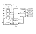
- FIG. 1 shows one example of the configuration of a focused ion beam system associated with one embodiment of the present invention. Note that some components of the focused ion beam system shown in FIG. 1 may be omitted.
- the focused ion beam system includes a body 1, an electrical drive arrangement 30, an amplifier 32, a sample stage controller 34, processing circuitry 40, a manual control portion 50, a display device 52, and a storage portion 54.
- the body 1 of the focused ion beam system includes an ion source 10, condenser lenses 12, a blanker 14, a movable aperture 16, a stigmator 18, an objective lens 20, a deflector 22, a sample stage 24, and a detector 26.
- the ion source 10 produces an ion beam B, which is extracted from the ion source 10 by an extractor electrode (not shown) and accelerated by an accelerating electrode (not shown).
- the condenser lenses 12 focus the ion beam B produced by the ion source 10.
- the blanker 14 blanks the ion beam B.
- the movable aperture 16 selectively limits the amount of current of the ion beam B.
- the stigmator 18 shapes the cross-sectional shape of the beam B to make the cross section of the impinging beam circular.
- the beam B is focused onto the surface of a sample or workpiece S by the objective lens 20.
- the deflector 22 causes the ion beam B focused by the objective lens 20 to be scanned over the sample S.
- the sample stage 24 moves the sample S horizontally or vertically and rotates or tilts the sample S.
- the detector 26 detects secondary electrons emanating from the sample S in response to the irradiation by the beam B.
- the detector 26 produces an output signal indicating the intensity of the secondary electrons.
- the output signal is amplified by the amplifier 32 and then supplied to the processing circuitry 40.
- the electrical drive arrangement 30 drives the condenser lenses 12, blanker 14, movable aperture 16, stigmator 18, objective lens 20, and deflector 22 in response to a control signal produced from the processing circuitry 40.
- the stage controller 34 controls the operation of the sample stage 24 in response to another control signal produced from the processing circuitry 40.
- the manual control portion 50 permits a user to enter manual control information.
- the manual control portion 50 outputs the entered manual control information to the processing circuitry 40.
- the function of the manual control portion 50 may be implemented by hardware such as a keyboard, a mouse, buttons, a touch panel display, or the like.
- An image (such as a secondary electron image of the sample S based on the scanning of the focused ion beam B) created by the processing circuitry 40 is displayed on the display device 52.
- the function of the display device can be implemented by an LCD, a CRT, or the like.
- Programs and various data permitting a computer to operate as various portions of the processing circuitry 40 are stored in the storage portion 54.
- the storage portion 54 acts as a working area for the processing circuitry 40.
- the function of the processing circuitry 40 can be implemented by a hard disc, a RAM, or the like.
- the processing circuitry 40 operates to control the electrical drive arrangement 30 and the stage controller 34. Furthermore, the processing circuitry 40 operates to synchronize the output signal from the amplifier 32 with a scanning signal for the ion beam B, the scanning signal being supplied to the deflector 22, and to generate image data representing a secondary electron image.
- the functions of the processing circuitry 40 can be implemented by hardware (such as various processors (e.g., a CPU, a DSP, or the like) or an ASIC (such as a gate array)) or software.
- the processing circuitry 40 includes a controller 42.
- the controller 42 generates a control signal and sends it to the electrical drive arrangement 30 to control the lens system including the condenser lenses 12, blanker 14, movable aperture 16, stigmator 18, objective lens 20, and deflector 22.
- the controller 42 of the present embodiment provides control to irradiate the sample S with the ion beam B without scanning the beam and varies the intensity of the objective lens 20 during irradiation by the beam B, thus varying the focus of the beam B. Furthermore, when the intensity of the objective lens 20 is being varied, the controller 42 detects the intensity of a signal indicating secondary electrons emanating from the sample S, and makes a focal adjustment of the ion beam B, based on the intensity of the objective lens 20 obtained when the detected intensity of the signal indicating secondary electrons is minimal. That is, the intensity of the objective lens 20 occurring when the detected intensity of the signal indicating secondary electrons is minimal is taken as the intensity of the objective lens 20 under a focused condition.
- the controller 42 may make a focal adjustment during processing of the sample or workpiece, based on the intensity of the objective lens 20 occurring when the detected intensity of the signal indicating secondary electrons is minimal. During observation of the sample or workpiece, the controller 42 may make a focal adjustment, based on a value offset a given value from the intensity of the objective lens 20 obtained when the detected intensity of the signal indicating secondary electrons is minimal.
- the controller 42 provides control to irradiate the sample S with the ion beam B without scanning the beam and to vary the intensity of the stigmator 18 during the irradiation by the beam B, thus varying the astigmatism in the beam B.
- the controller 42 detects the intensity of the signal indicating secondary electrons produced from the sample S while the intensity of the stigmator 18 is being varied, and makes a stigmatic correction of the ion beam B, based on the intensity of the stigmator 18 occurring when the detected intensity of the signal indicating secondary electrons is minimal.
- the intensity of the stigmator 18 occurring when the detected intensity of the signal indicating secondary electrons is minimal is taken as the intensity of the stigmator 18 used when astigmatism is corrected.
- the controller 42 may make a stigmatic correction during processing of the sample or workpiece, based on the intensity of the stigmator 18 obtained when the detected intensity of the signal indicating secondary electrons is minimal, and may make a stigmatic correction during observation of the sample, based on a value offset a given value from the intensity of the stigmator 18 obtained when the detected intensity of the signal indicating secondary electrons is minimal.
- FIGS. 1 and 2 The technique of the present embodiment is next described by referring to FIGS. 1 and 2 .
- the surface of the sample S is irradiated with the ion beam without scanning the beam.
- the focus of the ion beam is continuously varied while varying the intensity of the objective lens 20 during ion beam irradiation.
- the intensity of the signal indicating secondary electrons emanating from the sample S is measured while the intensity of the objective lens 20 is being varied.
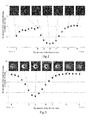
- FIG. 2 shows variations of the intensity of a signal indicating secondary electrons measured when a low-current ion beam was directed at a sample and the intensity of the objective lens was varied.
- FIG. 2 also shows secondary electron images taken when the intensity of the objective lens (i.e., the applied voltage) was adjusted to A, B, C, D, E, F, and G, respectively.
- the variations in the intensity of the signal indicating secondary electrons describe a downwardly convex curve having a valley.
- the intensity of the objective lens corresponding to this valley of the curve is obtained when the objective lens is in a focused condition. That is, the intensity of the objective lens obtained when the measured intensity of the signal indicating secondary electrons is minimal is the intensity of the objective lens under a focused condition.
- the intensity of the objective lens corresponding to the minimum level of the intensity of the signal indicating secondary electrons is D. It can be seen that the secondary electron image obtained at this time is best focused and that the intensity of the objective lens corresponding to the minimum level of the intensity of the signal indicating secondary electrons gives a focused condition.
- an ion beam is directed as a spot beam at the sample surface without scanning the beam, atoms at the surface of the sample are kicked off, forming holes in the surface of the sample.
- the ion beam is better focused, the holes formed in the sample surface become thinner and deeper.
- an ion beam having a sufficiently small probe diameter enters such thin and deep holes, the intensity of the signal indicating secondary electrons emanating from the sample decreases.
- the technique of the present embodiment takes notice of this phenomenon, i.e., as the ion beam impinging on the sample surface is better focused, the intensity of the signal indicating secondary electrons produced from the sample decreases.
- the sample surface is irradiated with an ion beam without scanning the beam while varying the intensity of the objective lens. A focal adjustment is made based on the intensity of the objective lens obtained when the measured intensity of the signal indicating secondary electrons is minimal.
- the ion beam can be focused without scanning the beam over the sample and, therefore, during a focal adjustment, damage to the sample due to the ion beam irradiation can be suppressed to a minimum. Furthermore, the time taken to scan the beam is dispensed with. Consequently, a focal adjustment can be performed in a short time. In addition, if there is no edge structure on the sample, the ion beam can be focused. Hence, a focal adjustment can be made without relying on the structure of the sample.
- FIG. 3 shows variations in the intensity of a signal indicating secondary electrons measured when an ion beam of a large current (10 nA or higher in this example) was directed at a sample and the intensity of the objective lens was varied.
- FIG. 3 also shows secondary electron images taken when the intensity of the objective lens (applied voltage) was adjusted to A, B, C, D, E, F, and G, respectively.
- a curve representing variations in the intensity of a signal indicating secondary electrons is downwardly convex and has a valley.
- the intensity of the objective lens corresponding to this valley of the curve is the intensity of the objective lens under an exactly focused condition.
- the intensity of the objective lens corresponding to the valley of the curve representing variations in the intensity of the signal indicating secondary electrons is C and denotes a correctly focused condition.
- a secondary electron image obtained when the intensity of the objective lens assumes a value corresponding to the valley of the curve representing variations in the signal indicating secondary electrons is C is not focused.
- a secondary electron image obtained when the intensity of the objective lens D is best focused indicates that, in the example shown in FIG. 3 , the position of the valley of the curve representing variations in the intensity of the signal indicating secondary electrons indicates a focal point during processing of a sample, not a focal point during imaging of the sample. This means that there is a deviation between a focal point occurring during processing of a sample and a focal point occurring during imaging in a case where the sample is irradiated with an ion beam of a large current.
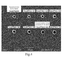
- FIG. 4 shows secondary electron images indicating holes left when spot ion-beam lithography was done by irradiating a sample with an ion beam of a large current adjusted to various focal values without scanning the beam.
- the focal value of the ion beam was set in conformity with a focal condition assumed during imaging of the sample and the sample was processed by the spot ion-beam lithography.
- the sample was processed similarly by ion-beam lithography while decrementing the focal value (the intensity of the objective lens) by aV. Since the holes were formed as a result of the spot ion-beam lithography, variations in gray level showing the holes represent a distribution of current densities of the ion beam.
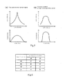
- the central portion of the beam is most sharply focused under a focused condition during imaging and that there are many scattering components of the beam around the central portion. If the central portion of the beam is narrowed down to a small area, the beam becomes adapted for imaging but the current density in the central portion of the beam decreases. Therefore, it is impossible to form deep holes and thus the beam is not suited for processing of the sample (see (A) of FIG. 5 ).
- a value offset a given amount of - aV from a value corresponding to a focal condition occurring during imaging indicates a focused condition occurring during processing of the sample.
- a value offset + 6aV from the value corresponding to the focal condition during processing of the sample gives a focal condition during imaging of the sample.
- a focal adjustment is made such that the intensity of the objective lens corresponding to the valley of the curve representing variations in the intensity of the signal indicating secondary electrons is taken as indicating a focused condition, in the same way as in the case where an ion beam of a low current is used.
- a focal adjustment may be made using a value offset a given value from the intensity of the objective lens corresponding to the valley position of the curve representing variations in the signal indicating secondary electrons as a value indicating a focused condition.
- the amount of offset (decremental amount) is previously measured and stored as a parameter intrinsic to the system in the storage portion 54. Since the amount of offset varies depending on the current of the ion beam and on the accelerating voltage, amounts of the offset corresponding to various combinations of the values of the current and accelerating voltage are previously measured and stored as data elements of a table in the storage portion 54 as shown in FIG. 6 .
- a focal adjustment is made, offset amounts corresponding to set values of current and accelerating voltage are read from this table, and a focal adjustment adapted for imaging of the sample is carried out.
- the technique of the present embodiment makes it possible to perform a focal adjustment adapted for processing of a sample and a focal adjustment adapted for imaging on the basis of the intensity of the objective lens obtained when the intensity of the signal indicating secondary electrons is minimal.
- a stigmatic correction of an ion beam can be made by a technique similar to the above-described focal adjustment.
- the surface of the sample S is irradiated with an ion beam without scanning the beam.
- the intensity of the stigmator 18 is varied to change the astigmatism in the ion beam continuously. While the intensity of the stigmator 18 is being varied, variations in the intensity of a signal indicating secondary electrons emanating from the sample S are measured, thus performing the stigmatic correction.
- a stigmatic correction is made such that the intensity of the stigmator 18 corresponding to the minimum value of the curve representing variations in the intensity of the signal indicating secondary electrons is taken as the intensity of the stigmator 18 used during correction of the astigmatism. Furthermore, when a sample is imaged and observed using an ion beam of a large current, a stigmatic correction is made such that a value offset a given amount from the intensity of the stigmator 18 corresponding to the minimum value of the curve representing variations in the intensity of secondary electrons is taken as the intensity of the stigmator 18 used during correction of astigmatism.
- the controller 42 controls the electrical drive arrangement 30 to irradiate the sample with an ion beam without scanning the beam (step S10).
- the position of the beam on the sample is determined by moving the sample stage 24 based on manual control information from the manual control portion 50.
- the controller 42 adjusts the intensity V (applied voltage) of the objective lens 20 to a given minimum value V min and varies (step S12).
- the intensity V of the objective lens 20 is varied from the given minimum value V min to a maximum value V max ⁇ This range is determined according to the set value of accelerating voltage of the ion beam.
- the controller 42 then obtains a signal indicating the intensity of a signal indicating secondary electrons, the signal being supplied from the amplifier 32 (step S14).
- the obtained signal intensity of secondary electrons is correlated with the intensity V of the objective lens 20 produced at this time, and is stored in the storage portion 54.
- the controller 42 then makes a decision as to whether the current value of the intensity V of the objective lens 20 has reached the given maximum value V max (step S16). If the decision at step S16 is No, indicating that the maximum value V max is not reached, the intensity V of the objective lens 20 is incremented by a given value ⁇ V ( ⁇ V ⁇ V max - V min ) (step S18). Control then goes to step S14. Steps S 14-S 18 are repeated until the intensity V of the objective lens 20 reaches the maximum value V max.
- step S16 If the decision at step S16 is Yes, indicating that the intensity V of the objective lens 20 has reached the maximum value V max , the controller 42 sets the intensity of the objective lens corresponding to a minimum value of the obtained intensity of the signal indicating secondary electrons as a focused-condition intensity and executes a focal adjustment (step S20). Where a focal adjustment is carried out during imaging of the sample, an offset amount is read from the table as shown in FIG. 6 at step S20. The focal adjustment is performed while taking a value offset from the intensity of the objective lens occurring when the intensity of the signal indicating secondary electrons is minimal as a focused-condition intensity, based on the obtained offset amount.
- the intensity V of the objective lens may be set to the maximum value V max .
- a decision may be made as to whether the intensity V of the objective lens has reached the minimum value V min .
- the intensity V of the objective lens 20 may be decremented by the given value ⁇ V.
- the present invention is not restricted to the above embodiment but rather various changes and modifications are possible.
- the present invention embraces configurations (e.g., configurations identical in function, method, and results or identical in purpose and advantageous effects) which are substantially identical to the configurations described in the above embodiment.
- the invention embraces configurations which are similar to the configurations described in the above embodiment except that their nonessential portions have been replaced.
- the invention embraces configurations which are similar to the configurations described in the above embodiment except that a well-known technique is added.
- a focal adjustment of an ion beam is made while varying the intensity of the objective lens.
- a focal adjustment of an ion beam may be made while varying the intensity of a focus lens equipped in a focused ion beam system.
Landscapes
- Chemical & Material Sciences (AREA)
- Analytical Chemistry (AREA)
- Electron Beam Exposure (AREA)
Abstract
Description
- The present invention relates to a focused ion beam system for directing a focused ion beam at a sample or a workpiece to process it and also to a method of making a focal adjustment of the ion beam.
- A known technique for making a focal adjustment in a focused ion beam system consists of varying the amount of adjustment of a beam optical system to produce various states, taking and displaying final images of a sample under these states, and repeating an operation for selecting a clear image, thus adjusting the focus (see, for example, patent document 1). Another known technique for making a focal adjustment consists of selecting a signal arising from edge structures of a sample and determining a focal position at which the signal becomes sharpest.
-
- Patent document 1:
JP-A-2000-048756 - In the above-described known method, it is necessary to scan the surface of a sample with an ion beam in order to obtain a final image and, therefore, etching of the ion beam damages a wide area on the sample. In the known method employing a signal arising from edge structures has the problem that a focal adjustment cannot be made unless any structure exists on the sample.
- In view of the problems described so far, the present invention has been made. According to some aspects of the invention, it is possible to offer a focused ion beam system capable of making a focal adjustment without depending on the structure of the sample while suppressing damage to the sample to a minimum. Also, a method of making a focal adjustment of the ion beam in this focused ion beam system is offered.
- (1) The present invention provides a focused ion beam system for irradiating a sample or a workpiece with a focused ion beam to process the sample. The focused ion beam system has an ion source for producing the ion beam, a lens system for focusing the ion beam onto the sample, a detector for detecting secondary electrons emanating from the sample, and a controller for controlling the lens system. The controller provides control such that the sample is irradiated with the ion beam without scanning the beam and that a focus of the ion beam is varied by varying the intensity of an objective lens during the ion beam irradiation. While the intensity of the objective lens is being varied, the intensity of a signal indicating secondary electrons emanating from the sample is measured. A focal adjustment of the ion beam is made on the basis of the intensity of the objective lens obtained when the measured intensity of the signal indicating secondary electrons is minimal.
- Furthermore, the invention provides a method of making a focal adjustment of an ion beam in a focused ion beam system. The method starts with irradiating a sample or a workpiece with the ion beam without scanning the beam. While the sample is being irradiated with the ion beam, the intensity of an objective lens is varied to thereby vary the focus of the ion beam. The intensity of a signal indicating secondary electrons produced from the sample while the intensity of the objective lens is being varied is measured. A focal adjustment of the ion beam is made on the basis of the intensity of the objective lens obtained when the measured intensity of the signal indicating secondary electrons is minimal.
- According to the present invention, the sample or workpiece is irradiated with the ion beam without scanning the beam, and a focal adjustment is made based on the intensity of the signal indicating secondary electrons emanating from the sample while the intensity of the objective lens is being varied. Thus, damage to the sample caused by the ion beam irradiation is suppressed to a minimum. Furthermore, the focal adjustment can be made without regard to the structure of the sample.
- (2) In one feature of the focused ion beam system and method of making a focal adjustment of the ion beam associated with the present invention, the controller makes a focal adjustment during processing of the sample on the basis of the intensity of the objective lens obtained when the measured intensity of the signal indicating secondary electrons is minimal. The controller may make a focal adjustment during imaging of the sample on the basis of a value that is offset a given value from the intensity of the objective lens obtained when the measured intensity of the signal indicating secondary electrons is minimal.
- According to the present invention, an optimum focal adjustment can be made during processing of a sample or a workpiece. Also, an optimum focal adjustment can be made during imaging of the sample.
- (3) In another feature of the focused ion beam system and method of making a focal adjustment of the ion beam associated with the present invention, the controller may provide control such that astigmatism in the ion beam is varied by varying the intensity of a stigmator during the irradiation by the ion beam. The intensity of the signal indicating secondary electrons emanating from the sample is measured while the intensity of the stigmator is being varied. A stigmatic correction of the ion beam may be made on the basis of the intensity of the stigmator obtained when the measured intensity of the signal indicating secondary electrons is minimal.
- According to the present invention, the sample is irradiated with the ion beam without scanning the beam, and a stigmatic correction is made based on the intensity of the signal indicating secondary electrons emanating from the sample while the intensity of the stigmator is being varied. This minimizes damage to the sample caused by the ion beam irradiation. Furthermore, a stigmatic correction can be made without relying on the structure of the sample.
-
-
FIG. 1 is a schematic vertical cross section, partly in block form, of a focused ion beam system associated with one embodiment of the present invention. -
FIG. 2 is a graph showing variations in the intensity of a signal indicating secondary electrons measured when a sample is irradiated with a low-current ion beam and the intensity of the objective lens shown inFIG. 1 is varied. -
FIG. 3 is a graph showing variations in the intensity of the signal indicating secondary electrons measured when the sample is irradiated with a large-current ion beam and the intensity of the objective lens is varied. -
FIG. 4 shows secondary electron images indicating holes formed by performing spot ion-beam lithography with various focal values. -
FIG. 5 shows graphs representing relationships between a current density distribution of a beam and a distribution of depths of formed holes. -
FIG. 6 is a table of offset amounts corresponding to various values of current and accelerating voltage. -
FIG. 7 is a flowchart illustrating one example of subroutine for making a focal adjustment in the focused ion beam system shown inFIG. 1 . - The preferred embodiments of the present invention are hereinafter described in detail with reference to the drawings. It is to be understood that the embodiments provided below do not unduly restrict the scope and content of the present invention delineated by the appended claims and that not all the configurations described below are essential constituent components of the invention.
-
FIG. 1 shows one example of the configuration of a focused ion beam system associated with one embodiment of the present invention. Note that some components of the focused ion beam system shown inFIG. 1 may be omitted. - As shown in
FIG. 1 , the focused ion beam system includes a body 1, anelectrical drive arrangement 30, anamplifier 32, asample stage controller 34,processing circuitry 40, amanual control portion 50, adisplay device 52, and astorage portion 54. The body 1 of the focused ion beam system includes anion source 10,condenser lenses 12, ablanker 14, amovable aperture 16, astigmator 18, anobjective lens 20, adeflector 22, asample stage 24, and adetector 26. - The
ion source 10 produces an ion beam B, which is extracted from theion source 10 by an extractor electrode (not shown) and accelerated by an accelerating electrode (not shown). Thecondenser lenses 12 focus the ion beam B produced by theion source 10. Theblanker 14 blanks the ion beam B. Themovable aperture 16 selectively limits the amount of current of the ion beam B. Thestigmator 18 shapes the cross-sectional shape of the beam B to make the cross section of the impinging beam circular. The beam B is focused onto the surface of a sample or workpiece S by theobjective lens 20. Thedeflector 22 causes the ion beam B focused by theobjective lens 20 to be scanned over the sample S. Thesample stage 24 moves the sample S horizontally or vertically and rotates or tilts the sample S. - The
detector 26 detects secondary electrons emanating from the sample S in response to the irradiation by the beam B. Thedetector 26 produces an output signal indicating the intensity of the secondary electrons. The output signal is amplified by theamplifier 32 and then supplied to theprocessing circuitry 40. - The
electrical drive arrangement 30 drives thecondenser lenses 12, blanker 14,movable aperture 16,stigmator 18,objective lens 20, anddeflector 22 in response to a control signal produced from theprocessing circuitry 40. Thestage controller 34 controls the operation of thesample stage 24 in response to another control signal produced from theprocessing circuitry 40. - The
manual control portion 50 permits a user to enter manual control information. Themanual control portion 50 outputs the entered manual control information to theprocessing circuitry 40. The function of themanual control portion 50 may be implemented by hardware such as a keyboard, a mouse, buttons, a touch panel display, or the like. - An image (such as a secondary electron image of the sample S based on the scanning of the focused ion beam B) created by the
processing circuitry 40 is displayed on thedisplay device 52. The function of the display device can be implemented by an LCD, a CRT, or the like. - Programs and various data permitting a computer to operate as various portions of the
processing circuitry 40 are stored in thestorage portion 54. Thestorage portion 54 acts as a working area for theprocessing circuitry 40. The function of theprocessing circuitry 40 can be implemented by a hard disc, a RAM, or the like. - The
processing circuitry 40 operates to control theelectrical drive arrangement 30 and thestage controller 34. Furthermore, theprocessing circuitry 40 operates to synchronize the output signal from theamplifier 32 with a scanning signal for the ion beam B, the scanning signal being supplied to thedeflector 22, and to generate image data representing a secondary electron image. The functions of theprocessing circuitry 40 can be implemented by hardware (such as various processors (e.g., a CPU, a DSP, or the like) or an ASIC (such as a gate array)) or software. Theprocessing circuitry 40 includes acontroller 42. - The
controller 42 generates a control signal and sends it to theelectrical drive arrangement 30 to control the lens system including thecondenser lenses 12, blanker 14,movable aperture 16,stigmator 18,objective lens 20, anddeflector 22. - During a focal adjustment, the
controller 42 of the present embodiment provides control to irradiate the sample S with the ion beam B without scanning the beam and varies the intensity of theobjective lens 20 during irradiation by the beam B, thus varying the focus of the beam B. Furthermore, when the intensity of theobjective lens 20 is being varied, thecontroller 42 detects the intensity of a signal indicating secondary electrons emanating from the sample S, and makes a focal adjustment of the ion beam B, based on the intensity of theobjective lens 20 obtained when the detected intensity of the signal indicating secondary electrons is minimal. That is, the intensity of theobjective lens 20 occurring when the detected intensity of the signal indicating secondary electrons is minimal is taken as the intensity of theobjective lens 20 under a focused condition. Alternatively, thecontroller 42 may make a focal adjustment during processing of the sample or workpiece, based on the intensity of theobjective lens 20 occurring when the detected intensity of the signal indicating secondary electrons is minimal. During observation of the sample or workpiece, thecontroller 42 may make a focal adjustment, based on a value offset a given value from the intensity of theobjective lens 20 obtained when the detected intensity of the signal indicating secondary electrons is minimal. - During a stigmatic correction, the
controller 42 provides control to irradiate the sample S with the ion beam B without scanning the beam and to vary the intensity of thestigmator 18 during the irradiation by the beam B, thus varying the astigmatism in the beam B. In addition, thecontroller 42 detects the intensity of the signal indicating secondary electrons produced from the sample S while the intensity of thestigmator 18 is being varied, and makes a stigmatic correction of the ion beam B, based on the intensity of thestigmator 18 occurring when the detected intensity of the signal indicating secondary electrons is minimal. That is, the intensity of thestigmator 18 occurring when the detected intensity of the signal indicating secondary electrons is minimal is taken as the intensity of thestigmator 18 used when astigmatism is corrected. Alternatively, thecontroller 42 may make a stigmatic correction during processing of the sample or workpiece, based on the intensity of thestigmator 18 obtained when the detected intensity of the signal indicating secondary electrons is minimal, and may make a stigmatic correction during observation of the sample, based on a value offset a given value from the intensity of thestigmator 18 obtained when the detected intensity of the signal indicating secondary electrons is minimal. - The technique of the present embodiment is next described by referring to
FIGS. 1 and2 . - In the technique of the focal adjustment of the present embodiment, the surface of the sample S is irradiated with the ion beam without scanning the beam. The focus of the ion beam is continuously varied while varying the intensity of the
objective lens 20 during ion beam irradiation. The intensity of the signal indicating secondary electrons emanating from the sample S is measured while the intensity of theobjective lens 20 is being varied. Thus, a focal adjustment is made. -
FIG. 2 shows variations of the intensity of a signal indicating secondary electrons measured when a low-current ion beam was directed at a sample and the intensity of the objective lens was varied.FIG. 2 also shows secondary electron images taken when the intensity of the objective lens (i.e., the applied voltage) was adjusted to A, B, C, D, E, F, and G, respectively. - As shown in
FIG. 2 , the variations in the intensity of the signal indicating secondary electrons describe a downwardly convex curve having a valley. The intensity of the objective lens corresponding to this valley of the curve is obtained when the objective lens is in a focused condition. That is, the intensity of the objective lens obtained when the measured intensity of the signal indicating secondary electrons is minimal is the intensity of the objective lens under a focused condition. In the example shown inFIG. 2 , the intensity of the objective lens corresponding to the minimum level of the intensity of the signal indicating secondary electrons is D. It can be seen that the secondary electron image obtained at this time is best focused and that the intensity of the objective lens corresponding to the minimum level of the intensity of the signal indicating secondary electrons gives a focused condition. - If an ion beam is directed as a spot beam at the sample surface without scanning the beam, atoms at the surface of the sample are kicked off, forming holes in the surface of the sample. When the ion beam is better focused, the holes formed in the sample surface become thinner and deeper. If an ion beam having a sufficiently small probe diameter enters such thin and deep holes, the intensity of the signal indicating secondary electrons emanating from the sample decreases. The technique of the present embodiment takes notice of this phenomenon, i.e., as the ion beam impinging on the sample surface is better focused, the intensity of the signal indicating secondary electrons produced from the sample decreases. The sample surface is irradiated with an ion beam without scanning the beam while varying the intensity of the objective lens. A focal adjustment is made based on the intensity of the objective lens obtained when the measured intensity of the signal indicating secondary electrons is minimal.
- According to the technique of the present embodiment, the ion beam can be focused without scanning the beam over the sample and, therefore, during a focal adjustment, damage to the sample due to the ion beam irradiation can be suppressed to a minimum. Furthermore, the time taken to scan the beam is dispensed with. Consequently, a focal adjustment can be performed in a short time. In addition, if there is no edge structure on the sample, the ion beam can be focused. Hence, a focal adjustment can be made without relying on the structure of the sample.
-
FIG. 3 shows variations in the intensity of a signal indicating secondary electrons measured when an ion beam of a large current (10 nA or higher in this example) was directed at a sample and the intensity of the objective lens was varied.FIG. 3 also shows secondary electron images taken when the intensity of the objective lens (applied voltage) was adjusted to A, B, C, D, E, F, and G, respectively. - In the example shown in
FIG. 3 , in the same way as in the example shown inFIG. 2 , a curve representing variations in the intensity of a signal indicating secondary electrons is downwardly convex and has a valley. The intensity of the objective lens corresponding to this valley of the curve is the intensity of the objective lens under an exactly focused condition. In the example shown inFIG. 3 , the intensity of the objective lens corresponding to the valley of the curve representing variations in the intensity of the signal indicating secondary electrons is C and denotes a correctly focused condition. In the example shown inFIG. 3 , a secondary electron image obtained when the intensity of the objective lens assumes a value corresponding to the valley of the curve representing variations in the signal indicating secondary electrons is C is not focused. Rather, a secondary electron image obtained when the intensity of the objective lens D is best focused. This indicates that, in the example shown inFIG. 3 , the position of the valley of the curve representing variations in the intensity of the signal indicating secondary electrons indicates a focal point during processing of a sample, not a focal point during imaging of the sample. This means that there is a deviation between a focal point occurring during processing of a sample and a focal point occurring during imaging in a case where the sample is irradiated with an ion beam of a large current. -
FIG. 4 shows secondary electron images indicating holes left when spot ion-beam lithography was done by irradiating a sample with an ion beam of a large current adjusted to various focal values without scanning the beam. First, the focal value of the ion beam was set in conformity with a focal condition assumed during imaging of the sample and the sample was processed by the spot ion-beam lithography. Then, the sample was processed similarly by ion-beam lithography while decrementing the focal value (the intensity of the objective lens) by aV. Since the holes were formed as a result of the spot ion-beam lithography, variations in gray level showing the holes represent a distribution of current densities of the ion beam. - It can be seen from
FIG. 4 that the central portion of the beam is most sharply focused under a focused condition during imaging and that there are many scattering components of the beam around the central portion. If the central portion of the beam is narrowed down to a small area, the beam becomes adapted for imaging but the current density in the central portion of the beam decreases. Therefore, it is impossible to form deep holes and thus the beam is not suited for processing of the sample (see (A) ofFIG. 5 ). - It is seen that when the focal value was decremented from a value obtained under a focused condition during imaging, the central portion of the beam gradually thickened but the region of the scattering components of the beam narrowed. This increased the current density in the central portion of the beam, making it possible to form deep holes. The beam became adapted for processing of the sample (see (B) of
FIG. 5 ). A focal value at which the region of the scattering components of the beam has disappeared indicates a focused condition during processing of the sample. This coincides with the valley of the curve representing variations in the intensity of the signal indicating secondary electrons shown inFIG. 3 . In the example shown inFIG. 4 , a value offset a given amount of - aV from a value corresponding to a focal condition occurring during imaging indicates a focused condition occurring during processing of the sample. In other words, a value offset + 6aV from the value corresponding to the focal condition during processing of the sample gives a focal condition during imaging of the sample. - Accordingly, when a sample or workpiece is processed using an ion beam of a large current, a focal adjustment is made such that the intensity of the objective lens corresponding to the valley of the curve representing variations in the intensity of the signal indicating secondary electrons is taken as indicating a focused condition, in the same way as in the case where an ion beam of a low current is used. Where the sample is imaged (i.e., to obtain a secondary image of the sample) using an ion beam of a large current, a focal adjustment may be made using a value offset a given value from the intensity of the objective lens corresponding to the valley position of the curve representing variations in the signal indicating secondary electrons as a value indicating a focused condition. The amount of offset (decremental amount) is previously measured and stored as a parameter intrinsic to the system in the
storage portion 54. Since the amount of offset varies depending on the current of the ion beam and on the accelerating voltage, amounts of the offset corresponding to various combinations of the values of the current and accelerating voltage are previously measured and stored as data elements of a table in thestorage portion 54 as shown inFIG. 6 . When a focal adjustment is made, offset amounts corresponding to set values of current and accelerating voltage are read from this table, and a focal adjustment adapted for imaging of the sample is carried out. In this way, the technique of the present embodiment makes it possible to perform a focal adjustment adapted for processing of a sample and a focal adjustment adapted for imaging on the basis of the intensity of the objective lens obtained when the intensity of the signal indicating secondary electrons is minimal. - A stigmatic correction of an ion beam can be made by a technique similar to the above-described focal adjustment. In particular, the surface of the sample S is irradiated with an ion beam without scanning the beam. During the ion beam irradiation, the intensity of the
stigmator 18 is varied to change the astigmatism in the ion beam continuously. While the intensity of thestigmator 18 is being varied, variations in the intensity of a signal indicating secondary electrons emanating from the sample S are measured, thus performing the stigmatic correction. That is, a stigmatic correction is made such that the intensity of the stigmator 18 corresponding to the minimum value of the curve representing variations in the intensity of the signal indicating secondary electrons is taken as the intensity of thestigmator 18 used during correction of the astigmatism. Furthermore, when a sample is imaged and observed using an ion beam of a large current, a stigmatic correction is made such that a value offset a given amount from the intensity of the stigmator 18 corresponding to the minimum value of the curve representing variations in the intensity of secondary electrons is taken as the intensity of thestigmator 18 used during correction of astigmatism. In this way, according to the technique of the present embodiment, even when astigmatism is corrected, damage to the sample due to ion beam irradiation can be suppressed to a minimum. In addition, a stigmatic correction can be made in a short time without relying on the structure of the sample. - One example of the operation of the focused ion beam system of the present embodiment to make a focal adjustment is next described by referring to the flowchart of
FIG. 7 . - First, the
controller 42 controls theelectrical drive arrangement 30 to irradiate the sample with an ion beam without scanning the beam (step S10). The position of the beam on the sample is determined by moving thesample stage 24 based on manual control information from themanual control portion 50. - Then, the
controller 42 adjusts the intensity V (applied voltage) of theobjective lens 20 to a given minimum value Vmin and varies (step S12). The intensity V of theobjective lens 20 is varied from the given minimum value Vmin to a maximum value Vmax· This range is determined according to the set value of accelerating voltage of the ion beam. - The
controller 42 then obtains a signal indicating the intensity of a signal indicating secondary electrons, the signal being supplied from the amplifier 32 (step S14). The obtained signal intensity of secondary electrons is correlated with the intensity V of theobjective lens 20 produced at this time, and is stored in thestorage portion 54. - The
controller 42 then makes a decision as to whether the current value of the intensity V of theobjective lens 20 has reached the given maximum value Vmax (step S16). If the decision at step S16 is No, indicating that the maximum value Vmax is not reached, the intensity V of theobjective lens 20 is incremented by a given value ΔV (ΔV < Vmax - Vmin) (step S18). Control then goes to step S14. Steps S 14-S 18 are repeated until the intensity V of theobjective lens 20 reaches the maximum value Vmax. - If the decision at step S16 is Yes, indicating that the intensity V of the
objective lens 20 has reached the maximum value Vmax, thecontroller 42 sets the intensity of the objective lens corresponding to a minimum value of the obtained intensity of the signal indicating secondary electrons as a focused-condition intensity and executes a focal adjustment (step S20). Where a focal adjustment is carried out during imaging of the sample, an offset amount is read from the table as shown inFIG. 6 at step S20. The focal adjustment is performed while taking a value offset from the intensity of the objective lens occurring when the intensity of the signal indicating secondary electrons is minimal as a focused-condition intensity, based on the obtained offset amount. - Alternatively, at step S12, the intensity V of the objective lens may be set to the maximum value Vmax. At step S16, a decision may be made as to whether the intensity V of the objective lens has reached the minimum value Vmin. At step S18, the intensity V of the
objective lens 20 may be decremented by the given value ΔV. - It is to be noted that the present invention is not restricted to the above embodiment but rather various changes and modifications are possible. The present invention embraces configurations (e.g., configurations identical in function, method, and results or identical in purpose and advantageous effects) which are substantially identical to the configurations described in the above embodiment. Furthermore, the invention embraces configurations which are similar to the configurations described in the above embodiment except that their nonessential portions have been replaced. Further, the invention embraces configurations which are similar to the configurations described in the above embodiment except that a well-known technique is added.
- For instance, in the description of the above embodiment, a focal adjustment of an ion beam is made while varying the intensity of the objective lens. Alternatively, a focal adjustment of an ion beam may be made while varying the intensity of a focus lens equipped in a focused ion beam system.
Claims (4)
- A focused ion beam system for irradiating a sample or a workpiece with a focused ion beam to process the sample, said focused ion beam system comprising:an ion source for producing the ion beam;a lens system for focusing the ion beam onto the sample;a detector for detecting secondary electrons emanating from the sample; anda controller for controlling the lens system;wherein said controller is operative to provide control such that the sample is irradiated with the ion beam without scanning the beam and that a focus of the ion beam is varied by varying the intensity of the objective lens during the ion beam irradiation, to measure the intensity of a signal indicating secondary electrons emanating from the sample while the intensity of the objective lens is being varied, and to make a focal adjustment of the ion beam on the basis of the intensity of the objective lens obtained when the measured intensity of the signal indicating secondary electrons is minimal.
- A focused ion beam system as set forth in claim 1, wherein said controller makes a focal adjustment during processing of the sample on the basis of the intensity of the objective lens obtained when the measured intensity of the signal indicating secondary electrons is minimal, and wherein said controller makes a focal adjustment during imaging of the sample on the basis of a value that is offset a given value from the intensity of the objective lens obtained when the measured intensity of the signal indicating secondary electrons is minimal.
- A focused ion beam system as set forth in any one of claims 1 and 2, wherein said controller is operative to provide control such that astigmatism in the ion beam is varied by varying the intensity of a stigmator during the irradiation by the ion beam, to measure the intensity of the signal indicating secondary electrons emanating from the sample while the intensity of the stigmator is being varied, and to make a stigmatic correction of the ion beam on the basis of the intensity of the stigmator obtained when the measured intensity of the signal indicating secondary electrons is minimal.
- A method of making a focal adjustment of an ion beam in a focused ion beam system, said method comprising the steps of:irradiating a sample or a workpiece with the ion beam without scanning the beam;varying a focus of the ion beam by varying the intensity of an objective lens during the ion beam irradiation;measuring the intensity of a signal indicating secondary electrons emanating from the sample while the intensity of the objective lens is being varied; andmaking a focal adjustment of the ion beam on the basis of the intensity of the objective lens obtained when the measured intensity of the signal indicating secondary electrons is minimal.
Applications Claiming Priority (1)
| Application Number | Priority Date | Filing Date | Title |
|---|---|---|---|
| JP2013234900A JP6266312B2 (en) | 2013-11-13 | 2013-11-13 | Focused ion beam apparatus and ion beam focus adjustment method |
Publications (2)
| Publication Number | Publication Date |
|---|---|
| EP2874176A1 true EP2874176A1 (en) | 2015-05-20 |
| EP2874176B1 EP2874176B1 (en) | 2016-07-06 |
Family
ID=51868836
Family Applications (1)
| Application Number | Title | Priority Date | Filing Date |
|---|---|---|---|
| EP14191939.9A Active EP2874176B1 (en) | 2013-11-13 | 2014-11-05 | Focused ion beam system and method of making focal adjustment of ion beam |
Country Status (3)
| Country | Link |
|---|---|
| US (1) | US9646805B2 (en) |
| EP (1) | EP2874176B1 (en) |
| JP (1) | JP6266312B2 (en) |
Cited By (1)
| Publication number | Priority date | Publication date | Assignee | Title |
|---|---|---|---|---|
| CN106252248A (en) * | 2015-06-15 | 2016-12-21 | 台湾积体电路制造股份有限公司 | For the method making in semiconductor fabrication there is the wafer mapper of the charged particle beam of focusing |
Families Citing this family (4)
| Publication number | Priority date | Publication date | Assignee | Title |
|---|---|---|---|---|
| JP6266312B2 (en) * | 2013-11-13 | 2018-01-24 | 日本電子株式会社 | Focused ion beam apparatus and ion beam focus adjustment method |
| US10410828B2 (en) * | 2014-12-22 | 2019-09-10 | Carl Zeiss Microscopy, Llc | Charged particle beam system and methods |
| JP7040927B2 (en) * | 2017-12-01 | 2022-03-23 | 株式会社日立ハイテク | Image pickup condition adjustment method in charged particle beam device and charged particle beam device |
| JP7407846B2 (en) | 2022-01-20 | 2024-01-04 | 日本電子株式会社 | Focused ion beam device and ion beam field of view deviation correction method |
Citations (3)
| Publication number | Priority date | Publication date | Assignee | Title |
|---|---|---|---|---|
| JPH0329319A (en) * | 1989-06-26 | 1991-02-07 | Nippon Telegr & Teleph Corp <Ntt> | Focus adjustment method |
| US5198668A (en) * | 1990-12-27 | 1993-03-30 | Jeol Ltd. | Automatic focusing apparatus for scanning electron microscope |
| JP2000048756A (en) * | 1998-07-27 | 2000-02-18 | Seiko Instruments Inc | Method and apparatus for adjusting a charged particle beam optical system |
Family Cites Families (14)
| Publication number | Priority date | Publication date | Assignee | Title |
|---|---|---|---|---|
| JPS60175354A (en) * | 1984-02-20 | 1985-09-09 | Mitsubishi Electric Corp | Adjustment of focusing position of electron beam machine tool |
| FR2559695B1 (en) * | 1984-02-20 | 1995-04-21 | Mitsubishi Electric Corp | METHOD AND APPARATUS FOR DETECTING AND CONTROLLING THE POSITION OF AN ELECTRONIC WELDING BEAM |
| JPS6182985A (en) * | 1984-09-28 | 1986-04-26 | Mitsubishi Electric Corp | Automatic adjusting method of focus position of electron beam |
| JPS61240553A (en) * | 1985-04-18 | 1986-10-25 | Jeol Ltd | Device for drawing picture by the use of ion beam |
| JPS63119147A (en) * | 1986-11-07 | 1988-05-23 | Jeol Ltd | Focus condition detecting device of changed corpuscular beams |
| JPH01213950A (en) * | 1988-02-23 | 1989-08-28 | Jeol Ltd | Mass analyzer and ms/ms device using same |
| JP2926132B1 (en) * | 1998-01-23 | 1999-07-28 | セイコーインスツルメンツ株式会社 | Secondary ion image observation method using focused ion beam |
| US6476398B1 (en) * | 1999-03-05 | 2002-11-05 | Applied Materials, Inc. | Beam automation in charged-particle-beam systems |
| US7015481B2 (en) * | 2003-02-14 | 2006-03-21 | Jeol Ltd. | Charged-particle optical system |
| JP4328192B2 (en) * | 2003-12-12 | 2009-09-09 | 日本電子株式会社 | Multipole field generating device and aberration correcting device in charged particle optical system |
| JP2006313704A (en) * | 2005-05-09 | 2006-11-16 | Jeol Ltd | Focused ion beam device |
| JP5044813B2 (en) * | 2007-02-19 | 2012-10-10 | エスアイアイ・ナノテクノロジー株式会社 | Focused ion beam apparatus and charged particle optical system adjustment method |
| JP5373463B2 (en) * | 2009-04-16 | 2013-12-18 | 日本電子株式会社 | Automatic optimum focus adjustment device for transmission electron microscope |
| JP6266312B2 (en) * | 2013-11-13 | 2018-01-24 | 日本電子株式会社 | Focused ion beam apparatus and ion beam focus adjustment method |
-
2013
- 2013-11-13 JP JP2013234900A patent/JP6266312B2/en active Active
-
2014
- 2014-11-05 US US14/533,494 patent/US9646805B2/en active Active
- 2014-11-05 EP EP14191939.9A patent/EP2874176B1/en active Active
Patent Citations (4)
| Publication number | Priority date | Publication date | Assignee | Title |
|---|---|---|---|---|
| JPH0329319A (en) * | 1989-06-26 | 1991-02-07 | Nippon Telegr & Teleph Corp <Ntt> | Focus adjustment method |
| US5198668A (en) * | 1990-12-27 | 1993-03-30 | Jeol Ltd. | Automatic focusing apparatus for scanning electron microscope |
| JP2000048756A (en) * | 1998-07-27 | 2000-02-18 | Seiko Instruments Inc | Method and apparatus for adjusting a charged particle beam optical system |
| US6437330B1 (en) * | 1998-07-27 | 2002-08-20 | Seiko Instruments, Inc. | Method and apparatus for adjusting a charged particle beam of a beam optical system |
Cited By (2)
| Publication number | Priority date | Publication date | Assignee | Title |
|---|---|---|---|---|
| CN106252248A (en) * | 2015-06-15 | 2016-12-21 | 台湾积体电路制造股份有限公司 | For the method making in semiconductor fabrication there is the wafer mapper of the charged particle beam of focusing |
| CN106252248B (en) * | 2015-06-15 | 2019-05-21 | 台湾积体电路制造股份有限公司 | Method for imaging wafers with focused charged particle beams in semiconductor fabrication |
Also Published As
| Publication number | Publication date |
|---|---|
| US9646805B2 (en) | 2017-05-09 |
| EP2874176B1 (en) | 2016-07-06 |
| US20150136978A1 (en) | 2015-05-21 |
| JP6266312B2 (en) | 2018-01-24 |
| JP2015095397A (en) | 2015-05-18 |
Similar Documents
| Publication | Publication Date | Title |
|---|---|---|
| EP2874176B1 (en) | Focused ion beam system and method of making focal adjustment of ion beam | |
| US10984981B2 (en) | Charged particle beam device having inspection scan direction based on scan with smaller dose | |
| US20190362931A1 (en) | Charged Particle Beam Device | |
| JP2017016755A (en) | Charged particle beam device | |
| JP4194526B2 (en) | Charged particle beam adjustment method and charged particle beam apparatus | |
| EP3021280A1 (en) | Image evaluation method and charged particle beam device | |
| KR102155621B1 (en) | Charged particle ray apparatus | |
| WO2019194304A1 (en) | Electron microscope device, inspection system using electron microscope device, and inspection method using electron microscope device | |
| JP7369747B2 (en) | Charged particle beam device and image adjustment method | |
| US11152186B2 (en) | Charged particle beam device | |
| US11017982B2 (en) | Composite charged particle beam apparatus and control method thereof | |
| US11742177B2 (en) | Charged particle beam apparatus and control method thereof | |
| JP7407846B2 (en) | Focused ion beam device and ion beam field of view deviation correction method | |
| KR102922716B1 (en) | Charged particle beam system | |
| US10662059B2 (en) | Micro-electro-mechanical-systems processing method, and micro-electro-mechanical-systems processing apparatus | |
| US11031211B2 (en) | Charged particle beam device, and observation method and elemental analysis method using the same | |
| JP2010182423A (en) | Focal evaluation method of charged particle beam and charged particle beam device | |
| JP6403200B2 (en) | Film forming method and focused ion beam apparatus | |
| JP4231891B2 (en) | Charged particle beam adjustment method and charged particle beam apparatus | |
| JP6356551B2 (en) | Pattern height measuring device and pattern height measuring method | |
| JPH09204892A (en) | Focusing method in charged particle beam device | |
| JP2008112684A (en) | Method and apparatus for automatic astigmatism correction and focus adjustment in charged particle beam apparatus |
Legal Events
| Date | Code | Title | Description |
|---|---|---|---|
| PUAI | Public reference made under article 153(3) epc to a published international application that has entered the european phase |
Free format text: ORIGINAL CODE: 0009012 |
|
| 17P | Request for examination filed |
Effective date: 20141105 |
|
| AK | Designated contracting states |
Kind code of ref document: A1 Designated state(s): AL AT BE BG CH CY CZ DE DK EE ES FI FR GB GR HR HU IE IS IT LI LT LU LV MC MK MT NL NO PL PT RO RS SE SI SK SM TR |
|
| AX | Request for extension of the european patent |
Extension state: BA ME |
|
| R17P | Request for examination filed (corrected) |
Effective date: 20151119 |
|
| RBV | Designated contracting states (corrected) |
Designated state(s): AL AT BE BG CH CY CZ DE DK EE ES FI FR GB GR HR HU IE IS IT LI LT LU LV MC MK MT NL NO PL PT RO RS SE SI SK SM TR |
|
| GRAP | Despatch of communication of intention to grant a patent |
Free format text: ORIGINAL CODE: EPIDOSNIGR1 |
|
| INTG | Intention to grant announced |
Effective date: 20160118 |
|
| GRAS | Grant fee paid |
Free format text: ORIGINAL CODE: EPIDOSNIGR3 |
|
| GRAA | (expected) grant |
Free format text: ORIGINAL CODE: 0009210 |
|
| AK | Designated contracting states |
Kind code of ref document: B1 Designated state(s): AL AT BE BG CH CY CZ DE DK EE ES FI FR GB GR HR HU IE IS IT LI LT LU LV MC MK MT NL NO PL PT RO RS SE SI SK SM TR |
|
| REG | Reference to a national code |
Ref country code: GB Ref legal event code: FG4D |
|
| REG | Reference to a national code |
Ref country code: AT Ref legal event code: REF Ref document number: 811240 Country of ref document: AT Kind code of ref document: T Effective date: 20160715 Ref country code: CH Ref legal event code: EP |
|
| REG | Reference to a national code |
Ref country code: IE Ref legal event code: FG4D |
|
| REG | Reference to a national code |
Ref country code: DE Ref legal event code: R096 Ref document number: 602014002576 Country of ref document: DE |
|
| REG | Reference to a national code |
Ref country code: FR Ref legal event code: PLFP Year of fee payment: 3 |
|
| REG | Reference to a national code |
Ref country code: NL Ref legal event code: MP Effective date: 20160706 |
|
| REG | Reference to a national code |
Ref country code: LT Ref legal event code: MG4D |
|
| REG | Reference to a national code |
Ref country code: AT Ref legal event code: MK05 Ref document number: 811240 Country of ref document: AT Kind code of ref document: T Effective date: 20160706 |
|
| PG25 | Lapsed in a contracting state [announced via postgrant information from national office to epo] |
Ref country code: HR Free format text: LAPSE BECAUSE OF FAILURE TO SUBMIT A TRANSLATION OF THE DESCRIPTION OR TO PAY THE FEE WITHIN THE PRESCRIBED TIME-LIMIT Effective date: 20160706 Ref country code: FI Free format text: LAPSE BECAUSE OF FAILURE TO SUBMIT A TRANSLATION OF THE DESCRIPTION OR TO PAY THE FEE WITHIN THE PRESCRIBED TIME-LIMIT Effective date: 20160706 Ref country code: LT Free format text: LAPSE BECAUSE OF FAILURE TO SUBMIT A TRANSLATION OF THE DESCRIPTION OR TO PAY THE FEE WITHIN THE PRESCRIBED TIME-LIMIT Effective date: 20160706 Ref country code: NL Free format text: LAPSE BECAUSE OF FAILURE TO SUBMIT A TRANSLATION OF THE DESCRIPTION OR TO PAY THE FEE WITHIN THE PRESCRIBED TIME-LIMIT Effective date: 20160706 Ref country code: RS Free format text: LAPSE BECAUSE OF FAILURE TO SUBMIT A TRANSLATION OF THE DESCRIPTION OR TO PAY THE FEE WITHIN THE PRESCRIBED TIME-LIMIT Effective date: 20160706 Ref country code: NO Free format text: LAPSE BECAUSE OF FAILURE TO SUBMIT A TRANSLATION OF THE DESCRIPTION OR TO PAY THE FEE WITHIN THE PRESCRIBED TIME-LIMIT Effective date: 20161006 Ref country code: IT Free format text: LAPSE BECAUSE OF FAILURE TO SUBMIT A TRANSLATION OF THE DESCRIPTION OR TO PAY THE FEE WITHIN THE PRESCRIBED TIME-LIMIT Effective date: 20160706 Ref country code: IS Free format text: LAPSE BECAUSE OF FAILURE TO SUBMIT A TRANSLATION OF THE DESCRIPTION OR TO PAY THE FEE WITHIN THE PRESCRIBED TIME-LIMIT Effective date: 20161106 |
|
| PG25 | Lapsed in a contracting state [announced via postgrant information from national office to epo] |
Ref country code: ES Free format text: LAPSE BECAUSE OF FAILURE TO SUBMIT A TRANSLATION OF THE DESCRIPTION OR TO PAY THE FEE WITHIN THE PRESCRIBED TIME-LIMIT Effective date: 20160706 Ref country code: GR Free format text: LAPSE BECAUSE OF FAILURE TO SUBMIT A TRANSLATION OF THE DESCRIPTION OR TO PAY THE FEE WITHIN THE PRESCRIBED TIME-LIMIT Effective date: 20161007 Ref country code: PT Free format text: LAPSE BECAUSE OF FAILURE TO SUBMIT A TRANSLATION OF THE DESCRIPTION OR TO PAY THE FEE WITHIN THE PRESCRIBED TIME-LIMIT Effective date: 20161107 Ref country code: SE Free format text: LAPSE BECAUSE OF FAILURE TO SUBMIT A TRANSLATION OF THE DESCRIPTION OR TO PAY THE FEE WITHIN THE PRESCRIBED TIME-LIMIT Effective date: 20160706 Ref country code: PL Free format text: LAPSE BECAUSE OF FAILURE TO SUBMIT A TRANSLATION OF THE DESCRIPTION OR TO PAY THE FEE WITHIN THE PRESCRIBED TIME-LIMIT Effective date: 20160706 Ref country code: BE Free format text: LAPSE BECAUSE OF NON-PAYMENT OF DUE FEES Effective date: 20160706 Ref country code: LV Free format text: LAPSE BECAUSE OF FAILURE TO SUBMIT A TRANSLATION OF THE DESCRIPTION OR TO PAY THE FEE WITHIN THE PRESCRIBED TIME-LIMIT Effective date: 20160706 Ref country code: AT Free format text: LAPSE BECAUSE OF FAILURE TO SUBMIT A TRANSLATION OF THE DESCRIPTION OR TO PAY THE FEE WITHIN THE PRESCRIBED TIME-LIMIT Effective date: 20160706 |
|
| REG | Reference to a national code |
Ref country code: DE Ref legal event code: R097 Ref document number: 602014002576 Country of ref document: DE |
|
| PG25 | Lapsed in a contracting state [announced via postgrant information from national office to epo] |
Ref country code: RO Free format text: LAPSE BECAUSE OF FAILURE TO SUBMIT A TRANSLATION OF THE DESCRIPTION OR TO PAY THE FEE WITHIN THE PRESCRIBED TIME-LIMIT Effective date: 20160706 Ref country code: EE Free format text: LAPSE BECAUSE OF FAILURE TO SUBMIT A TRANSLATION OF THE DESCRIPTION OR TO PAY THE FEE WITHIN THE PRESCRIBED TIME-LIMIT Effective date: 20160706 |
|
| PLBE | No opposition filed within time limit |
Free format text: ORIGINAL CODE: 0009261 |
|
| STAA | Information on the status of an ep patent application or granted ep patent |
Free format text: STATUS: NO OPPOSITION FILED WITHIN TIME LIMIT |
|
| PG25 | Lapsed in a contracting state [announced via postgrant information from national office to epo] |
Ref country code: SK Free format text: LAPSE BECAUSE OF FAILURE TO SUBMIT A TRANSLATION OF THE DESCRIPTION OR TO PAY THE FEE WITHIN THE PRESCRIBED TIME-LIMIT Effective date: 20160706 Ref country code: DK Free format text: LAPSE BECAUSE OF FAILURE TO SUBMIT A TRANSLATION OF THE DESCRIPTION OR TO PAY THE FEE WITHIN THE PRESCRIBED TIME-LIMIT Effective date: 20160706 Ref country code: BG Free format text: LAPSE BECAUSE OF FAILURE TO SUBMIT A TRANSLATION OF THE DESCRIPTION OR TO PAY THE FEE WITHIN THE PRESCRIBED TIME-LIMIT Effective date: 20161006 Ref country code: SM Free format text: LAPSE BECAUSE OF FAILURE TO SUBMIT A TRANSLATION OF THE DESCRIPTION OR TO PAY THE FEE WITHIN THE PRESCRIBED TIME-LIMIT Effective date: 20160706 |
|
| 26N | No opposition filed |
Effective date: 20170407 |
|
| REG | Reference to a national code |
Ref country code: IE Ref legal event code: MM4A |
|
| PG25 | Lapsed in a contracting state [announced via postgrant information from national office to epo] |
Ref country code: SI Free format text: LAPSE BECAUSE OF FAILURE TO SUBMIT A TRANSLATION OF THE DESCRIPTION OR TO PAY THE FEE WITHIN THE PRESCRIBED TIME-LIMIT Effective date: 20160706 |
|
| PG25 | Lapsed in a contracting state [announced via postgrant information from national office to epo] |
Ref country code: LU Free format text: LAPSE BECAUSE OF NON-PAYMENT OF DUE FEES Effective date: 20161130 |
|
| REG | Reference to a national code |
Ref country code: FR Ref legal event code: PLFP Year of fee payment: 4 |
|
| PG25 | Lapsed in a contracting state [announced via postgrant information from national office to epo] |
Ref country code: IE Free format text: LAPSE BECAUSE OF NON-PAYMENT OF DUE FEES Effective date: 20161105 |
|
| PG25 | Lapsed in a contracting state [announced via postgrant information from national office to epo] |
Ref country code: HU Free format text: LAPSE BECAUSE OF FAILURE TO SUBMIT A TRANSLATION OF THE DESCRIPTION OR TO PAY THE FEE WITHIN THE PRESCRIBED TIME-LIMIT; INVALID AB INITIO Effective date: 20141105 |
|
| PG25 | Lapsed in a contracting state [announced via postgrant information from national office to epo] |
Ref country code: CY Free format text: LAPSE BECAUSE OF FAILURE TO SUBMIT A TRANSLATION OF THE DESCRIPTION OR TO PAY THE FEE WITHIN THE PRESCRIBED TIME-LIMIT Effective date: 20160706 Ref country code: MC Free format text: LAPSE BECAUSE OF FAILURE TO SUBMIT A TRANSLATION OF THE DESCRIPTION OR TO PAY THE FEE WITHIN THE PRESCRIBED TIME-LIMIT Effective date: 20160706 Ref country code: MK Free format text: LAPSE BECAUSE OF FAILURE TO SUBMIT A TRANSLATION OF THE DESCRIPTION OR TO PAY THE FEE WITHIN THE PRESCRIBED TIME-LIMIT Effective date: 20160706 |
|
| PG25 | Lapsed in a contracting state [announced via postgrant information from national office to epo] |
Ref country code: LI Free format text: LAPSE BECAUSE OF NON-PAYMENT OF DUE FEES Effective date: 20171130 Ref country code: CH Free format text: LAPSE BECAUSE OF NON-PAYMENT OF DUE FEES Effective date: 20171130 |
|
| PG25 | Lapsed in a contracting state [announced via postgrant information from national office to epo] |
Ref country code: MT Free format text: LAPSE BECAUSE OF NON-PAYMENT OF DUE FEES Effective date: 20161105 |
|
| PG25 | Lapsed in a contracting state [announced via postgrant information from national office to epo] |
Ref country code: AL Free format text: LAPSE BECAUSE OF FAILURE TO SUBMIT A TRANSLATION OF THE DESCRIPTION OR TO PAY THE FEE WITHIN THE PRESCRIBED TIME-LIMIT Effective date: 20160706 Ref country code: TR Free format text: LAPSE BECAUSE OF FAILURE TO SUBMIT A TRANSLATION OF THE DESCRIPTION OR TO PAY THE FEE WITHIN THE PRESCRIBED TIME-LIMIT Effective date: 20160706 |
|
| PGFP | Annual fee paid to national office [announced via postgrant information from national office to epo] |
Ref country code: DE Payment date: 20251119 Year of fee payment: 12 |
|
| PGFP | Annual fee paid to national office [announced via postgrant information from national office to epo] |
Ref country code: GB Payment date: 20251121 Year of fee payment: 12 |
|
| PGFP | Annual fee paid to national office [announced via postgrant information from national office to epo] |
Ref country code: FR Payment date: 20251125 Year of fee payment: 12 |
|
| PGFP | Annual fee paid to national office [announced via postgrant information from national office to epo] |
Ref country code: CZ Payment date: 20251029 Year of fee payment: 12 |