EP2874170B1 - Hauptstromkreisteil eines Vakuumstromkreisschalters mit selbstbetriebener Temperatursensoranordnung - Google Patents
Hauptstromkreisteil eines Vakuumstromkreisschalters mit selbstbetriebener Temperatursensoranordnung Download PDFInfo
- Publication number
- EP2874170B1 EP2874170B1 EP14181725.4A EP14181725A EP2874170B1 EP 2874170 B1 EP2874170 B1 EP 2874170B1 EP 14181725 A EP14181725 A EP 14181725A EP 2874170 B1 EP2874170 B1 EP 2874170B1
- Authority
- EP
- European Patent Office
- Prior art keywords
- temperature sensor
- main circuit
- circuit part
- self
- fixing plate
- Prior art date
- Legal status (The legal status is an assumption and is not a legal conclusion. Google has not performed a legal analysis and makes no representation as to the accuracy of the status listed.)
- Not-in-force
Links
- 238000004891 communication Methods 0.000 claims description 23
- 238000009529 body temperature measurement Methods 0.000 claims description 19
- 125000006850 spacer group Chemical group 0.000 claims description 5
- 239000000696 magnetic material Substances 0.000 claims description 3
- 238000009413 insulation Methods 0.000 description 6
- 238000012986 modification Methods 0.000 description 3
- 230000004048 modification Effects 0.000 description 3
- 238000012545 processing Methods 0.000 description 3
- 238000013461 design Methods 0.000 description 2
- 230000000694 effects Effects 0.000 description 2
- 238000012544 monitoring process Methods 0.000 description 2
- 230000018199 S phase Effects 0.000 description 1
- 239000004809 Teflon Substances 0.000 description 1
- 229920006362 Teflon® Polymers 0.000 description 1
- 229910052782 aluminium Inorganic materials 0.000 description 1
- XAGFODPZIPBFFR-UHFFFAOYSA-N aluminium Chemical compound [Al] XAGFODPZIPBFFR-UHFFFAOYSA-N 0.000 description 1
- 238000013459 approach Methods 0.000 description 1
- 239000010953 base metal Substances 0.000 description 1
- 230000015556 catabolic process Effects 0.000 description 1
- 239000004020 conductor Substances 0.000 description 1
- 230000007423 decrease Effects 0.000 description 1
- 230000006866 deterioration Effects 0.000 description 1
- 238000005516 engineering process Methods 0.000 description 1
- 230000020169 heat generation Effects 0.000 description 1
- 238000003780 insertion Methods 0.000 description 1
- 230000037431 insertion Effects 0.000 description 1
- 239000012212 insulator Substances 0.000 description 1
- 230000007257 malfunction Effects 0.000 description 1
- 239000000463 material Substances 0.000 description 1
- 238000005259 measurement Methods 0.000 description 1
- 230000002093 peripheral effect Effects 0.000 description 1
- 229910001220 stainless steel Inorganic materials 0.000 description 1
- 239000010935 stainless steel Substances 0.000 description 1
- 229920003002 synthetic resin Polymers 0.000 description 1
- 239000000057 synthetic resin Substances 0.000 description 1
- 238000012546 transfer Methods 0.000 description 1
Images



Classifications
-
- G—PHYSICS
- G01—MEASURING; TESTING
- G01K—MEASURING TEMPERATURE; MEASURING QUANTITY OF HEAT; THERMALLY-SENSITIVE ELEMENTS NOT OTHERWISE PROVIDED FOR
- G01K13/00—Thermometers specially adapted for specific purposes
-
- H—ELECTRICITY
- H01—ELECTRIC ELEMENTS
- H01H—ELECTRIC SWITCHES; RELAYS; SELECTORS; EMERGENCY PROTECTIVE DEVICES
- H01H33/00—High-tension or heavy-current switches with arc-extinguishing or arc-preventing means
- H01H33/60—Switches wherein the means for extinguishing or preventing the arc do not include separate means for obtaining or increasing flow of arc-extinguishing fluid
- H01H33/66—Vacuum switches
-
- H—ELECTRICITY
- H01—ELECTRIC ELEMENTS
- H01H—ELECTRIC SWITCHES; RELAYS; SELECTORS; EMERGENCY PROTECTIVE DEVICES
- H01H11/00—Apparatus or processes specially adapted for the manufacture of electric switches
- H01H11/0062—Testing or measuring non-electrical properties of switches, e.g. contact velocity
-
- G—PHYSICS
- G01—MEASURING; TESTING
- G01K—MEASURING TEMPERATURE; MEASURING QUANTITY OF HEAT; THERMALLY-SENSITIVE ELEMENTS NOT OTHERWISE PROVIDED FOR
- G01K1/00—Details of thermometers not specially adapted for particular types of thermometer
- G01K1/14—Supports; Fastening devices; Arrangements for mounting thermometers in particular locations
- G01K1/143—Supports; Fastening devices; Arrangements for mounting thermometers in particular locations for measuring surface temperatures
-
- H—ELECTRICITY
- H01—ELECTRIC ELEMENTS
- H01H—ELECTRIC SWITCHES; RELAYS; SELECTORS; EMERGENCY PROTECTIVE DEVICES
- H01H33/00—High-tension or heavy-current switches with arc-extinguishing or arc-preventing means
- H01H33/60—Switches wherein the means for extinguishing or preventing the arc do not include separate means for obtaining or increasing flow of arc-extinguishing fluid
- H01H33/66—Vacuum switches
- H01H33/6606—Terminal arrangements
-
- G—PHYSICS
- G01—MEASURING; TESTING
- G01K—MEASURING TEMPERATURE; MEASURING QUANTITY OF HEAT; THERMALLY-SENSITIVE ELEMENTS NOT OTHERWISE PROVIDED FOR
- G01K2215/00—Details concerning sensor power supply
-
- H—ELECTRICITY
- H01—ELECTRIC ELEMENTS
- H01H—ELECTRIC SWITCHES; RELAYS; SELECTORS; EMERGENCY PROTECTIVE DEVICES
- H01H11/00—Apparatus or processes specially adapted for the manufacture of electric switches
- H01H11/0062—Testing or measuring non-electrical properties of switches, e.g. contact velocity
- H01H2011/0068—Testing or measuring non-electrical properties of switches, e.g. contact velocity measuring the temperature of the switch or parts thereof
-
- H—ELECTRICITY
- H01—ELECTRIC ELEMENTS
- H01H—ELECTRIC SWITCHES; RELAYS; SELECTORS; EMERGENCY PROTECTIVE DEVICES
- H01H33/00—High-tension or heavy-current switches with arc-extinguishing or arc-preventing means
- H01H33/60—Switches wherein the means for extinguishing or preventing the arc do not include separate means for obtaining or increasing flow of arc-extinguishing fluid
- H01H33/66—Vacuum switches
- H01H33/6606—Terminal arrangements
- H01H2033/6613—Cooling arrangements directly associated with the terminal arrangements
Definitions
- the present invention relates to a main circuit part of a vacuum circuit breaker, and more particularly, to a main circuit part of a vacuum circuit breaker with a temperature sensor.
- a vacuum circuit breaker is a circuit breaker installed in a high voltage electric power system to break a circuit to protect the electric power system in the event of a dangerous situation such as a short circuit, an overcurrent, and the like, and it is designed by utilizing excellent insulating performance and arc-extinguishing capability in a vacuum state.
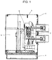
- FIG. 1 is a side view illustrating a main body of a vacuum circuit breaker according to the conventional art.
- the main body 1 of the vacuum circuit breaker generally includes a main circuit part 2, an operation part 3, and a transfer part 4.
- the part essential for applying or cutting off a circuit voltage or current is the main circuit part 2.
- Korean Patent Registration No. 10-0883042 titled 'Air Circuit Breaker with Temperature Sensor' may be referred.
- This invention relates to an air circuit breaker with a temperature sensor which can monitor the temperature of the circuit breaker based on the current flowing in a conduction unit of the air circuit breaker.
- the air circuit breaker with a temperature sensor according to an exemplary embodiment of this invention includes a temperature sensor 150 which is inserted into a sensor insertion hole 115 formed in a base mold 110 and measures temperatures and a temperature indicator 160 which indicates the temperature of the current-carrying part with a measurement made by the temperature sensor 150.
- a temperature sensor 5 may be installed in the air to measure the upper-air temperature of the main body 1 where the main circuit part's heat is transferred via convection (case A), or a temperature sensor 6 may be configured to come into contact with a mold housing or insulator to indirectly measure the temperature of heat transferred (case B).
- a cable for power supply and a cable for data communication are necessarily connected to the temperature sensor 5 or 6. That is, a power cable is connected to the temperature sensor 5 or 6 to supply power, and a data cable is connected to the temperature sensor 5 or 6 to transmit data measured by the temperature sensor 5 or 6 to an external device. It is hard for these cables to bear high-temperature heat generated from the main circuit part 2. Also, forming various types of cables within the main body 1 in a complicated manner may cause a deterioration of insulation performance and bring disadvantages in terms of spatial design.
- a temperature sensor has been installed in proximity to the main circuit part 2 in the same way as shown in FIG. 1 , which, however, decreases the accuracy of data measured by the temperature sensor installed in this way. This makes it difficult to accurately measure the temperature of the main circuit part 2 and gain practical benefits of monitoring. As a consequence, there still is a possibility that the main body 1 and peripheral equipment will get damage.
- the cable connected to the temperature sensor has to be pulled out to the front even when the temperature is installed directly on the main circuit part 2 to accurately measure the temperature of the main circuit part 2, which creates the possibility of insulation breakdown and failure due to the cable connected to the temperature sensor.
- Document EP2088609 discloses a device according to the preamble of claim 1.
- the present invention has been made in an effort to solve the above-mentioned problems and provide a temperature sensor assembly which can be installed directly on a main circuit part of a vacuum circuit breaker.
- the main circuit part further includes a radiator fin that is integrally attached to terminals, wherein the self-powered temperature sensor module is placed on a mounting part that is formed as a flat base at the center of the radiator fin.
- the self-powered temperature sensor module includes a temperature measurement part and a wireless communication module.
- the self-powered temperature sensor module includes a sensor radiator fin at the top of the temperature measurement part.
- the support bracket includes a body part and support wings, and the body part is shaped like a box, the bottom of which is fully opened and the front, rear, top, and sides are partially opened.
- the main circuit part further includes an upper fixing plate and a lower fixing plate that enclose and support the wireless communication module.
- the support bracket, the lower fixing plate, and the upper fixing plate are formed of a non-magnetic material.
- the upper fixing plate extends to the temperature measurement part and is attached to the support bracket.
- An insulative, shock-absorbing spacer is interposed between the wireless communication module and the upper fixing plate or between the wireless communication module and the lower fixing plate.
- the self-powered temperature sensor module produces an electromotive force by itself using a temperature difference between the top and bottom of the temperature measurement part.
- a temperature sensor may be installed in direct contact with the upper terminal or lower terminal of the main circuit part. Accordingly, the temperature at the terminals of the main circuit part can be accurately measured.
- a main circuit part of a vacuum circuit breaker with a self-powered temperature sensor assembly includes: a self-powered temperature sensor module 25 installed on part of terminals of the main circuit part; and a support bracket 30 enclosing and supporting the self-powered temperature sensor module 25.
- FIG. 2 is a perspective view of a vacuum circuit breaker with a self-powered temperature sensor assembly according to an embodiment of the present invention.
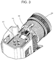
- FIG. 3 is a partial detailed view of A of FIG. 2 .
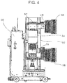
- FIG. 4 is a side view of FIG. 2 .
- FIG. 5a illustrates a self-powered temperature sensor assembly according to an embodiment of the present invention.
- FIG. 5b illustrates the self-powered temperature sensor assembly of FIG. 5a being attached to a radiator fin.
- FIG. 6 is an exploded perspective view of FIG. 5b .
- FIG. 2 depicts a main body 50 of the vacuum circuit breaker.
- An upper terminal 56 and a lower terminal 58 protrude from the main circuit part 52.
- a radiator fin 57 is attached to each of the terminals 56 and 58 to efficiently release heat generated by large-current conduction.
- a current entering the power supply side goes out to the lower terminal 58 through the upper terminal 56 and a vacuum interrupter 54 and is connected to a load.
- a flexible shunt 55 may be interposed between the vacuum interrupter 54 and the lower terminal 58 to provide a flexible clearance for moving a movable part of the vacuum interrupter 54.
- the main circuit part 52 of this type is usually provided in three phases (R phase, S phase, and T phase) on the main body 50, and only one of the three phases will be described because the three phases are formed and work in the same manner.
- a radiator fin 10 is integrally attached to the upper terminal 56 or the lower terminal 58.
- the radiator fin 10 may be a modification of the existing radiator fin 57.
- the radiator fin 10 may have an angular U-shape.
- a mounting part 11 comprising a flat base is formed at the center of the radiator fin 10.
- a plurality of finned parts 12 are formed on both sides of the mounting part 11.
- the radiator fin 10 is preferably formed of a highly heat-conductive material, like aluminum.
- the self-powered temperature sensor assembly 20 is attached to the radiator fin 10.
- the self-powered temperature sensor assembly 20 to be applied to an embodiment of the present invention may be optionally installed, together with the radiator fin 10, on the upper terminal 56 or the lower terminal 58.
- the self-powered temperature sensor assembly 20 is equipped with a self-powered temperature sensor module 25.
- the self-powered temperature sensor module 25 includes a temperature measurement part 26 and a wireless communication module 27.
- the temperature measurement part 26 directly measures the temperature of heat generated by the current flowing in the upper terminal 56 or lower terminal 58 of the main circuit part 55. Accordingly, the temperature of heat generated from each of the terminals 56 and 58 can be accurately measured without error.
- the temperature measurement part 26 can operate without a power supply unit, an example of which may include a self-powered approach using a temperature difference. That is, the temperature measurement part 26 may produce an electromotive force by itself using a temperature difference between the top and bottom of the temperature measurement part 26.
- a sensor radiator fin 28 may be provided at the top of the temperature measurement part 26.
- the sensor radiator fin 28 causes heat generated from the temperature measurement part 26 to be released, thereby making the temperature at the top lower than the temperature at the bottom.
- the wireless communication module 27 is capable of wireless data communication with the outside (receiver).
- an RF (radio frequency) module may be used for this wireless communication.
- the wireless communication 27 may transmit data measured by the temperature measurement part 26 to different types of receivers for users, such as an external switchboard or laptop computer, to enable the processing and control of this data according to settings. Accordingly, processing and controlling equipment may perform control operations, such as indicating numerical values on a display part or sounding an alarm or automatically operating the circuit breaker when the temperature rises to more than a set temperature.
- no cable for connection to the outside (receiver) is required. This can eliminate the space needed for cables, facilitate spatial design, and improve insulation performance.
- there is no risk of accidents such as a fire and desired effects can be obtained in terms of cost reduction.
- the self-powered temperature sensor module 25 may be further equipped with a processor for processing data between the temperature measurement part 26 and the wireless communication module 27.
- the support bracket 30 is provided to fixedly support the self-powered temperature sensor module 25 and the sensor radiator fin 28.
- the support bracket 30 may be formed of a box-shaped body part 31 and support wings 32 extending laterally from the bottom end of the body part 31.
- the bottom of the body part 31 is fully opened, its front and rear are opened, except for some part, and the top and sides are opened, except for the outer frame. This is to guarantee the maximum performance of the sensor radiator fin 28 enclosed by the body part 31.
- the support wings 32 have a plurality of screw holes so as to be fixedly attached to the radiator fin 10.
- An upper fixing plate 35 and a lower fixing plate 40 are provided to enclose and support the wireless communication module 27.
- the upper fixing plate 35 may be formed of an upper side 36 large enough to enclose and cover the wireless communication module 27 and lateral sides 37 of a predetermined height. Supporting faces 38 may be bent at and extend from the bottom of the lateral sides 37, and the supporting faces 38 may have screw holes. The lateral sides 37 and the supporting faces 38 may extend rearward to the temperature measurement part 26. Accordingly, the upper fixing plate 35, together with the support bracket 30, may be fixedly installed on the radiator fin 10.
- the support bracket 30 and the upper fixing plate 35 may be integrally formed.
- the lower fixing plate 40 may have a width corresponding to the upper side 36 and supporting faces 38 of the upper fixing plate 35, and include a front side 41.
- the wireless communication module 27 is stably protected and perform its function.
- the support bracket 30, the upper fixing plate 35, and the lower fixing plate 40 are formed of a non-magnetic material to minimize its effect on insulation performance. Moreover, the support bracket 30, the upper fixing plate 35, and the lower fixing plate 40 must have sufficient bearing capacity.
- An example of this material includes a stainless steel base metal. Accordingly, any malfunction which may occur due to heat generated from the temperature measurement part 26 and the wireless communication module 27 and a magnetic force formed around them can be prevented.
- An insulative, shock-absorbing spacer 45 may be interposed between the wireless communication module 27 and the upper fixing plate 35.
- a spacer 46 may be interposed between the wireless communication module 27 and the lower fixing plate 40.
- These spacers 45 and 46 may be of a Teflon synthetic resin to provide high insulation performance.
Landscapes
- Physics & Mathematics (AREA)
- General Physics & Mathematics (AREA)
- Engineering & Computer Science (AREA)
- Manufacturing & Machinery (AREA)
- Measuring Temperature Or Quantity Of Heat (AREA)
- High-Tension Arc-Extinguishing Switches Without Spraying Means (AREA)
- Arc-Extinguishing Devices That Are Switches (AREA)
- Thermally Actuated Switches (AREA)
Claims (9)
- Hauptschaltungsteil eines Vakuumleistungsschalters mit einer Temperatursensoranordnung, umfassend:ein Temperatursensormodul (25), das an einem Teil eines Hauptschaltungsteilanschlusses (56, 58) angeordnet ist; undeine Unterstützungshalterung (30), die das Temperatursensormodul (25) umschließt und unterstützt,dadurch gekennzeichnet, dassdas Temperatursensormodul (25) selbstbetrieben ist, wobei das selbstbetriebene Temperatursensormodul (25) eine elektromotorische Kraft von selbst unter Verwendung eines Temperaturunterschieds zwischen dem oberen Teil und dem unteren Teil des Temperaturmessteils produziert.
- Hauptschaltungsteil nach Anspruch 1, weiterhin umfassend eine Kühlrippe (10), die einstückig mit den Anschlüssen (56, 58) befestigt ist,
wobei das selbstbetriebene Temperatursensormodul (25) auf einem Montageteil (11) angeordnet ist, der als flache Basis im Zentrum der Kühlrippe (10) gebildet ist. - Hauptschaltungsteil nach einem der vorhergehenden Ansprüche, wobei das selbstbetriebene Temperatursensormodul (25) einen Temperaturmessteil (26) und ein drahtloses Kommunikationsmodul (27) umfasst.
- Hauptschaltungsteil nach Anspruch 3, bei welchem das selbstbetriebene Temperatursensormodul (25) eine Sensorkühlrippe (28) oben auf dem Temperaturmessteil (26) umfasst.
- Hauptschaltungsteil nach einem der vorhergehenden Ansprüche, bei welchem die Unterstützungshalterung (30) einen Körperteil (31) und Unterstützungsflügel (32) enthält und der Körperteil (31) wie ein Kasten geformt ist, dessen Unterseite vollständig geöffnet ist und dessen Vorderseite, Rückseite, Oberseite und Seiten teilweise geöffnet sind.
- Hauptschaltungsteil nach Anspruch 3, bei welchem der Hauptschaltungsteil weiterhin eine obere Befestigungsplatte (35) und eine untere Befestigungsplatte (40) enthält, die das drahtlose Kommunikationsmodul (27) einschließen und unterstützen.
- Hauptschaltungsteil nach Anspruch 6, bei welchem die Unterstützungshalterung (30), die obere Befestigungsplatte (35) und die untere Befestigungsplatte (40) aus einem nichtmagnetischen Material gebildet sind.
- Hauptschaltungsteil nach Anspruch 6 oder 7, bei welchem die obere Befestigungsplatte (35) sich zum Temperaturmessteil (26) erstreckt und mit der Unterstützungshalterung (30) befestigt ist.
- Hauptschaltungsteil nach einem der Ansprüche 6 bis 8, bei welchem die isolierende, stoßdämpfende Abstandshalter (45, 46) zwischen dem drahtlosen Kommunikationsmodul (27) und der oberen Befestigungsplatte (35) oder zwischen dem drahtlosen Kommunikationsmodul (27) und der unteren Befestigungsplatte (40) dazwischen gestellt sind.
Applications Claiming Priority (1)
| Application Number | Priority Date | Filing Date | Title |
|---|---|---|---|
| KR1020130140028A KR101564991B1 (ko) | 2013-11-18 | 2013-11-18 | 자가발전 온도센서 어셈블리가 구비된 진공회로차단기 주회로부 |
Publications (2)
| Publication Number | Publication Date |
|---|---|
| EP2874170A1 EP2874170A1 (de) | 2015-05-20 |
| EP2874170B1 true EP2874170B1 (de) | 2016-07-13 |
Family
ID=51383627
Family Applications (1)
| Application Number | Title | Priority Date | Filing Date |
|---|---|---|---|
| EP14181725.4A Not-in-force EP2874170B1 (de) | 2013-11-18 | 2014-08-21 | Hauptstromkreisteil eines Vakuumstromkreisschalters mit selbstbetriebener Temperatursensoranordnung |
Country Status (6)
| Country | Link |
|---|---|
| US (1) | US9766137B2 (de) |
| EP (1) | EP2874170B1 (de) |
| JP (1) | JP5841213B2 (de) |
| KR (1) | KR101564991B1 (de) |
| CN (1) | CN104658809B (de) |
| ES (1) | ES2596447T3 (de) |
Families Citing this family (16)
| Publication number | Priority date | Publication date | Assignee | Title |
|---|---|---|---|---|
| CN104992875A (zh) * | 2015-07-09 | 2015-10-21 | 新疆特变电工自控设备有限公司 | 智能型高原高寒真空断路器 |
| CN107017568B (zh) * | 2016-01-28 | 2022-02-01 | Abb瑞士股份有限公司 | 嵌入杆及其组装方法 |
| USD829659S1 (en) * | 2016-05-17 | 2018-10-02 | Eaton Intelligent Power Limited | Conductor |
| US9767978B1 (en) | 2016-05-17 | 2017-09-19 | Eaton Corporation | Medium voltage breaker conductor with an electrically efficient contour |
| USD829660S1 (en) * | 2016-05-17 | 2018-10-02 | Eaton Intelligent Power Limited | Conductor |
| US10249459B2 (en) * | 2016-09-19 | 2019-04-02 | Eaton Intelligent Power Limited | Advanced cooling system for electrical equipment |
| DE102018213625A1 (de) * | 2018-08-13 | 2020-02-13 | Siemens Aktiengesellschaft | Schaltanlagentemperaturmessung |
| CN111403939B (zh) * | 2019-01-02 | 2025-05-27 | 上海量乘机电科技有限公司 | 电器装置及其电连接装置 |
| CN110286265B (zh) * | 2019-07-24 | 2024-05-10 | 河北杰能电气设备有限公司 | 用于真空断路器的触臂测量环形装置 |
| CN110349798A (zh) * | 2019-08-13 | 2019-10-18 | 麦克奥迪(厦门)机电科技有限公司 | 一种智能测温固封极柱 |
| EP3836184B1 (de) * | 2019-12-11 | 2024-02-07 | Siemens Aktiengesellschaft | Belüftungsverbindereinheit für schutzschalter |
| CN112017873A (zh) * | 2020-08-25 | 2020-12-01 | 王云保 | 一种集成无线测温传感器的断路器 |
| KR102674084B1 (ko) * | 2021-03-31 | 2024-06-12 | 엘에스일렉트릭(주) | 진공 차단기 |
| KR102674083B1 (ko) * | 2021-03-31 | 2024-06-12 | 엘에스일렉트릭(주) | 진공 차단기 |
| KR102501590B1 (ko) * | 2021-03-31 | 2023-02-21 | 엘에스일렉트릭(주) | 진공 차단기 |
| CN117650638A (zh) * | 2022-08-17 | 2024-03-05 | 施耐德电器工业公司 | 电气设备及电气设备系统 |
Family Cites Families (20)
| Publication number | Priority date | Publication date | Assignee | Title |
|---|---|---|---|---|
| JPH04212645A (ja) | 1991-03-29 | 1992-08-04 | Iseki & Co Ltd | 動力車輌の運搬装置 |
| JPH0963430A (ja) | 1995-08-25 | 1997-03-07 | Toshiba Corp | 開閉器 |
| JP2003139621A (ja) | 2001-11-05 | 2003-05-14 | Denso Corp | 温度センサおよびその取付構造 |
| KR100475065B1 (ko) | 2002-03-21 | 2005-03-10 | 엘지산전 주식회사 | 가스절연 차단기의 소호장치 |
| JP2004024551A (ja) | 2002-06-26 | 2004-01-29 | Renesas Technology Corp | センサシステム用半導体装置 |
| JP4908146B2 (ja) * | 2006-10-12 | 2012-04-04 | 株式会社東芝 | センサ付きicタグ適用高電圧機器 |
| KR100883042B1 (ko) | 2007-08-20 | 2009-02-09 | 엘에스산전 주식회사 | 온도센서를 구비한 기중차단기 |
| US7910852B2 (en) | 2008-02-07 | 2011-03-22 | Eaton Corporation | Encapsulated pole unit conductor assembly for an encapsulated pole unit and medium voltage circuit interrupter including the same |
| KR100996791B1 (ko) * | 2008-04-10 | 2010-11-25 | 엘에스산전 주식회사 | 진공차단기의 주회로 단자 어셈블리 |
| KR200450605Y1 (ko) | 2008-06-27 | 2010-10-14 | 엘에스산전 주식회사 | 가스절연개폐기 |
| CN201522959U (zh) | 2009-11-19 | 2010-07-07 | 上海西屋开关有限公司 | 智能型高压真空断路器 |
| CN202013834U (zh) | 2009-11-26 | 2011-10-19 | 大连理工大学 | 一种直立型多断口模块式高压真空断路器 |
| US20110150036A1 (en) * | 2009-12-21 | 2011-06-23 | Electronics And Telecommunications Research Institute | Flexible thermoelectric generator, wireless sensor node including the same and method of manufacturing the same |
| JP5578047B2 (ja) * | 2010-11-22 | 2014-08-27 | ヤマハ株式会社 | 温度監視装置及び温度監視システム |
| US9263659B2 (en) * | 2011-06-10 | 2016-02-16 | Perpetua Power Source Technologies, Inc. | System and method for thermal protection of an electronics module of an energy harvester |
| WO2013057925A1 (ja) | 2011-10-17 | 2013-04-25 | 三菱電機株式会社 | 電気機器の状態監視装置 |
| KR101279061B1 (ko) | 2011-12-22 | 2013-07-02 | 주식회사 포스코 | 전력용 차단기 |
| US20130304385A1 (en) * | 2012-05-08 | 2013-11-14 | Logimesh IP, LLC | Holding tank monitoring system |
| US9472744B2 (en) * | 2012-10-04 | 2016-10-18 | Marlow Industries, Inc. | System for thermoelectric energy generation |
| CN202957190U (zh) | 2012-11-30 | 2013-05-29 | 北海银河开关设备有限公司 | 智能断路器 |
-
2013
- 2013-11-18 KR KR1020130140028A patent/KR101564991B1/ko active Active
-
2014
- 2014-08-19 US US14/463,447 patent/US9766137B2/en not_active Expired - Fee Related
- 2014-08-21 ES ES14181725.4T patent/ES2596447T3/es active Active
- 2014-08-21 EP EP14181725.4A patent/EP2874170B1/de not_active Not-in-force
- 2014-09-09 JP JP2014182874A patent/JP5841213B2/ja not_active Expired - Fee Related
- 2014-11-11 CN CN201410645565.5A patent/CN104658809B/zh not_active Expired - Fee Related
Also Published As
| Publication number | Publication date |
|---|---|
| US20150139275A1 (en) | 2015-05-21 |
| KR20150057107A (ko) | 2015-05-28 |
| JP2015099769A (ja) | 2015-05-28 |
| ES2596447T3 (es) | 2017-01-09 |
| CN104658809B (zh) | 2017-04-12 |
| CN104658809A (zh) | 2015-05-27 |
| JP5841213B2 (ja) | 2016-01-13 |
| EP2874170A1 (de) | 2015-05-20 |
| KR101564991B1 (ko) | 2015-11-03 |
| US9766137B2 (en) | 2017-09-19 |
Similar Documents
| Publication | Publication Date | Title |
|---|---|---|
| EP2874170B1 (de) | Hauptstromkreisteil eines Vakuumstromkreisschalters mit selbstbetriebener Temperatursensoranordnung | |
| EP2256757B1 (de) | Stromtransformator und zugehörige Schutzvorrichtung und Trennschalter mit solch einem Transformator | |
| CN215911371U (zh) | 数据交换设备、装置 | |
| US20160380518A1 (en) | Motor Temperature Monitoring | |
| WO2014088715A1 (en) | Circuit breaker terminal shield with position indicator | |
| EP3330993B1 (de) | Leistungsschalter mit gegossenem gehäuse | |
| US9810717B2 (en) | Device for measuring at least one electric quantity of a current intended to circulate in an electric apparatus, and assembly comprising such a device | |
| EP3753037B1 (de) | Drahtloses erfassungssystem und verfahren für eine schaltanlage | |
| EP3987558B1 (de) | Trennschalter mit stromerfassung | |
| US11923163B2 (en) | Fuse element and fuse | |
| EP2685480B1 (de) | Kontaktanordnung eines Schalters | |
| CN103636087B (zh) | 温度监视装置及温度监视方法 | |
| KR101670304B1 (ko) | 주회로부 온도 센서가 구비된 진공차단기 | |
| KR101856710B1 (ko) | 바이메탈을 이용한 화재 예방 충전 장치 | |
| CN211016921U (zh) | 一种温度电流双重保护热保护器 | |
| JPWO2012066792A1 (ja) | ブッシング | |
| JP6984029B2 (ja) | 配線用遮断器の電子式トリップ装置 | |
| JP5908300B2 (ja) | 回路遮断器 | |
| KR20230137712A (ko) | 초고압 차단기의 온도 측정 장치 | |
| HK1193680B (en) | Temperature monitoring device and temperature monitoring method | |
| JP2020089199A (ja) | 受電装置、給電装置及び配線システム | |
| CN105679617A (zh) | 多功能插头式断路器 |
Legal Events
| Date | Code | Title | Description |
|---|---|---|---|
| PUAI | Public reference made under article 153(3) epc to a published international application that has entered the european phase |
Free format text: ORIGINAL CODE: 0009012 |
|
| 17P | Request for examination filed |
Effective date: 20140821 |
|
| AK | Designated contracting states |
Kind code of ref document: A1 Designated state(s): AL AT BE BG CH CY CZ DE DK EE ES FI FR GB GR HR HU IE IS IT LI LT LU LV MC MK MT NL NO PL PT RO RS SE SI SK SM TR |
|
| AX | Request for extension of the european patent |
Extension state: BA ME |
|
| R17P | Request for examination filed (corrected) |
Effective date: 20151119 |
|
| RBV | Designated contracting states (corrected) |
Designated state(s): AL AT BE BG CH CY CZ DE DK EE ES FI FR GB GR HR HU IE IS IT LI LT LU LV MC MK MT NL NO PL PT RO RS SE SI SK SM TR |
|
| GRAP | Despatch of communication of intention to grant a patent |
Free format text: ORIGINAL CODE: EPIDOSNIGR1 |
|
| INTG | Intention to grant announced |
Effective date: 20160127 |
|
| GRAS | Grant fee paid |
Free format text: ORIGINAL CODE: EPIDOSNIGR3 |
|
| GRAA | (expected) grant |
Free format text: ORIGINAL CODE: 0009210 |
|
| AK | Designated contracting states |
Kind code of ref document: B1 Designated state(s): AL AT BE BG CH CY CZ DE DK EE ES FI FR GB GR HR HU IE IS IT LI LT LU LV MC MK MT NL NO PL PT RO RS SE SI SK SM TR |
|
| REG | Reference to a national code |
Ref country code: GB Ref legal event code: FG4D |
|
| REG | Reference to a national code |
Ref country code: AT Ref legal event code: REF Ref document number: 812907 Country of ref document: AT Kind code of ref document: T Effective date: 20160715 Ref country code: CH Ref legal event code: EP |
|
| REG | Reference to a national code |
Ref country code: IE Ref legal event code: FG4D |
|
| REG | Reference to a national code |
Ref country code: DE Ref legal event code: R096 Ref document number: 602014002639 Country of ref document: DE |
|
| REG | Reference to a national code |
Ref country code: FR Ref legal event code: PLFP Year of fee payment: 3 |
|
| REG | Reference to a national code |
Ref country code: LT Ref legal event code: MG4D |
|
| REG | Reference to a national code |
Ref country code: NL Ref legal event code: MP Effective date: 20160713 |
|
| REG | Reference to a national code |
Ref country code: AT Ref legal event code: MK05 Ref document number: 812907 Country of ref document: AT Kind code of ref document: T Effective date: 20160713 |
|
| PG25 | Lapsed in a contracting state [announced via postgrant information from national office to epo] |
Ref country code: BE Free format text: LAPSE BECAUSE OF NON-PAYMENT OF DUE FEES Effective date: 20160831 |
|
| REG | Reference to a national code |
Ref country code: ES Ref legal event code: FG2A Ref document number: 2596447 Country of ref document: ES Kind code of ref document: T3 Effective date: 20170109 |
|
| PG25 | Lapsed in a contracting state [announced via postgrant information from national office to epo] |
Ref country code: FI Free format text: LAPSE BECAUSE OF FAILURE TO SUBMIT A TRANSLATION OF THE DESCRIPTION OR TO PAY THE FEE WITHIN THE PRESCRIBED TIME-LIMIT Effective date: 20160713 Ref country code: HR Free format text: LAPSE BECAUSE OF FAILURE TO SUBMIT A TRANSLATION OF THE DESCRIPTION OR TO PAY THE FEE WITHIN THE PRESCRIBED TIME-LIMIT Effective date: 20160713 Ref country code: LT Free format text: LAPSE BECAUSE OF FAILURE TO SUBMIT A TRANSLATION OF THE DESCRIPTION OR TO PAY THE FEE WITHIN THE PRESCRIBED TIME-LIMIT Effective date: 20160713 Ref country code: RS Free format text: LAPSE BECAUSE OF FAILURE TO SUBMIT A TRANSLATION OF THE DESCRIPTION OR TO PAY THE FEE WITHIN THE PRESCRIBED TIME-LIMIT Effective date: 20160713 Ref country code: NL Free format text: LAPSE BECAUSE OF FAILURE TO SUBMIT A TRANSLATION OF THE DESCRIPTION OR TO PAY THE FEE WITHIN THE PRESCRIBED TIME-LIMIT Effective date: 20160713 Ref country code: IS Free format text: LAPSE BECAUSE OF FAILURE TO SUBMIT A TRANSLATION OF THE DESCRIPTION OR TO PAY THE FEE WITHIN THE PRESCRIBED TIME-LIMIT Effective date: 20161113 Ref country code: NO Free format text: LAPSE BECAUSE OF FAILURE TO SUBMIT A TRANSLATION OF THE DESCRIPTION OR TO PAY THE FEE WITHIN THE PRESCRIBED TIME-LIMIT Effective date: 20161013 |
|
| PG25 | Lapsed in a contracting state [announced via postgrant information from national office to epo] |
Ref country code: SE Free format text: LAPSE BECAUSE OF FAILURE TO SUBMIT A TRANSLATION OF THE DESCRIPTION OR TO PAY THE FEE WITHIN THE PRESCRIBED TIME-LIMIT Effective date: 20160713 Ref country code: AT Free format text: LAPSE BECAUSE OF FAILURE TO SUBMIT A TRANSLATION OF THE DESCRIPTION OR TO PAY THE FEE WITHIN THE PRESCRIBED TIME-LIMIT Effective date: 20160713 Ref country code: GR Free format text: LAPSE BECAUSE OF FAILURE TO SUBMIT A TRANSLATION OF THE DESCRIPTION OR TO PAY THE FEE WITHIN THE PRESCRIBED TIME-LIMIT Effective date: 20161014 Ref country code: LV Free format text: LAPSE BECAUSE OF FAILURE TO SUBMIT A TRANSLATION OF THE DESCRIPTION OR TO PAY THE FEE WITHIN THE PRESCRIBED TIME-LIMIT Effective date: 20160713 Ref country code: PT Free format text: LAPSE BECAUSE OF FAILURE TO SUBMIT A TRANSLATION OF THE DESCRIPTION OR TO PAY THE FEE WITHIN THE PRESCRIBED TIME-LIMIT Effective date: 20161114 Ref country code: PL Free format text: LAPSE BECAUSE OF FAILURE TO SUBMIT A TRANSLATION OF THE DESCRIPTION OR TO PAY THE FEE WITHIN THE PRESCRIBED TIME-LIMIT Effective date: 20160713 Ref country code: BE Free format text: LAPSE BECAUSE OF FAILURE TO SUBMIT A TRANSLATION OF THE DESCRIPTION OR TO PAY THE FEE WITHIN THE PRESCRIBED TIME-LIMIT Effective date: 20160713 |
|
| REG | Reference to a national code |
Ref country code: DE Ref legal event code: R097 Ref document number: 602014002639 Country of ref document: DE |
|
| PG25 | Lapsed in a contracting state [announced via postgrant information from national office to epo] |
Ref country code: RO Free format text: LAPSE BECAUSE OF FAILURE TO SUBMIT A TRANSLATION OF THE DESCRIPTION OR TO PAY THE FEE WITHIN THE PRESCRIBED TIME-LIMIT Effective date: 20160713 Ref country code: MC Free format text: LAPSE BECAUSE OF FAILURE TO SUBMIT A TRANSLATION OF THE DESCRIPTION OR TO PAY THE FEE WITHIN THE PRESCRIBED TIME-LIMIT Effective date: 20160713 Ref country code: EE Free format text: LAPSE BECAUSE OF FAILURE TO SUBMIT A TRANSLATION OF THE DESCRIPTION OR TO PAY THE FEE WITHIN THE PRESCRIBED TIME-LIMIT Effective date: 20160713 |
|
| PLBE | No opposition filed within time limit |
Free format text: ORIGINAL CODE: 0009261 |
|
| STAA | Information on the status of an ep patent application or granted ep patent |
Free format text: STATUS: NO OPPOSITION FILED WITHIN TIME LIMIT |
|
| PG25 | Lapsed in a contracting state [announced via postgrant information from national office to epo] |
Ref country code: BG Free format text: LAPSE BECAUSE OF FAILURE TO SUBMIT A TRANSLATION OF THE DESCRIPTION OR TO PAY THE FEE WITHIN THE PRESCRIBED TIME-LIMIT Effective date: 20161013 Ref country code: CZ Free format text: LAPSE BECAUSE OF FAILURE TO SUBMIT A TRANSLATION OF THE DESCRIPTION OR TO PAY THE FEE WITHIN THE PRESCRIBED TIME-LIMIT Effective date: 20160713 Ref country code: SM Free format text: LAPSE BECAUSE OF FAILURE TO SUBMIT A TRANSLATION OF THE DESCRIPTION OR TO PAY THE FEE WITHIN THE PRESCRIBED TIME-LIMIT Effective date: 20160713 Ref country code: SK Free format text: LAPSE BECAUSE OF FAILURE TO SUBMIT A TRANSLATION OF THE DESCRIPTION OR TO PAY THE FEE WITHIN THE PRESCRIBED TIME-LIMIT Effective date: 20160713 Ref country code: DK Free format text: LAPSE BECAUSE OF FAILURE TO SUBMIT A TRANSLATION OF THE DESCRIPTION OR TO PAY THE FEE WITHIN THE PRESCRIBED TIME-LIMIT Effective date: 20160713 |
|
| REG | Reference to a national code |
Ref country code: IE Ref legal event code: MM4A |
|
| 26N | No opposition filed |
Effective date: 20170418 |
|
| REG | Reference to a national code |
Ref country code: FR Ref legal event code: PLFP Year of fee payment: 4 |
|
| PG25 | Lapsed in a contracting state [announced via postgrant information from national office to epo] |
Ref country code: IE Free format text: LAPSE BECAUSE OF NON-PAYMENT OF DUE FEES Effective date: 20160821 |
|
| PG25 | Lapsed in a contracting state [announced via postgrant information from national office to epo] |
Ref country code: LU Free format text: LAPSE BECAUSE OF NON-PAYMENT OF DUE FEES Effective date: 20160821 Ref country code: SI Free format text: LAPSE BECAUSE OF FAILURE TO SUBMIT A TRANSLATION OF THE DESCRIPTION OR TO PAY THE FEE WITHIN THE PRESCRIBED TIME-LIMIT Effective date: 20160713 |
|
| REG | Reference to a national code |
Ref country code: CH Ref legal event code: PL |
|
| PG25 | Lapsed in a contracting state [announced via postgrant information from national office to epo] |
Ref country code: LI Free format text: LAPSE BECAUSE OF NON-PAYMENT OF DUE FEES Effective date: 20170831 Ref country code: CH Free format text: LAPSE BECAUSE OF NON-PAYMENT OF DUE FEES Effective date: 20170831 |
|
| PG25 | Lapsed in a contracting state [announced via postgrant information from national office to epo] |
Ref country code: HU Free format text: LAPSE BECAUSE OF FAILURE TO SUBMIT A TRANSLATION OF THE DESCRIPTION OR TO PAY THE FEE WITHIN THE PRESCRIBED TIME-LIMIT; INVALID AB INITIO Effective date: 20140821 |
|
| REG | Reference to a national code |
Ref country code: FR Ref legal event code: PLFP Year of fee payment: 5 |
|
| PG25 | Lapsed in a contracting state [announced via postgrant information from national office to epo] |
Ref country code: CY Free format text: LAPSE BECAUSE OF FAILURE TO SUBMIT A TRANSLATION OF THE DESCRIPTION OR TO PAY THE FEE WITHIN THE PRESCRIBED TIME-LIMIT Effective date: 20160713 Ref country code: MK Free format text: LAPSE BECAUSE OF FAILURE TO SUBMIT A TRANSLATION OF THE DESCRIPTION OR TO PAY THE FEE WITHIN THE PRESCRIBED TIME-LIMIT Effective date: 20160713 Ref country code: MT Free format text: LAPSE BECAUSE OF NON-PAYMENT OF DUE FEES Effective date: 20160831 |
|
| PG25 | Lapsed in a contracting state [announced via postgrant information from national office to epo] |
Ref country code: AL Free format text: LAPSE BECAUSE OF FAILURE TO SUBMIT A TRANSLATION OF THE DESCRIPTION OR TO PAY THE FEE WITHIN THE PRESCRIBED TIME-LIMIT Effective date: 20160713 Ref country code: TR Free format text: LAPSE BECAUSE OF FAILURE TO SUBMIT A TRANSLATION OF THE DESCRIPTION OR TO PAY THE FEE WITHIN THE PRESCRIBED TIME-LIMIT Effective date: 20160713 |
|
| PGFP | Annual fee paid to national office [announced via postgrant information from national office to epo] |
Ref country code: FR Payment date: 20200609 Year of fee payment: 7 |
|
| PGFP | Annual fee paid to national office [announced via postgrant information from national office to epo] |
Ref country code: GB Payment date: 20200608 Year of fee payment: 7 |
|
| PGFP | Annual fee paid to national office [announced via postgrant information from national office to epo] |
Ref country code: DE Payment date: 20200605 Year of fee payment: 7 Ref country code: ES Payment date: 20200911 Year of fee payment: 7 |
|
| REG | Reference to a national code |
Ref country code: DE Ref legal event code: R119 Ref document number: 602014002639 Country of ref document: DE |
|
| GBPC | Gb: european patent ceased through non-payment of renewal fee |
Effective date: 20210821 |
|
| PG25 | Lapsed in a contracting state [announced via postgrant information from national office to epo] |
Ref country code: GB Free format text: LAPSE BECAUSE OF NON-PAYMENT OF DUE FEES Effective date: 20210821 Ref country code: FR Free format text: LAPSE BECAUSE OF NON-PAYMENT OF DUE FEES Effective date: 20210831 Ref country code: DE Free format text: LAPSE BECAUSE OF NON-PAYMENT OF DUE FEES Effective date: 20220301 |
|
| PGFP | Annual fee paid to national office [announced via postgrant information from national office to epo] |
Ref country code: IT Payment date: 20220606 Year of fee payment: 9 |
|
| REG | Reference to a national code |
Ref country code: ES Ref legal event code: FD2A Effective date: 20221006 |
|
| PG25 | Lapsed in a contracting state [announced via postgrant information from national office to epo] |
Ref country code: ES Free format text: LAPSE BECAUSE OF NON-PAYMENT OF DUE FEES Effective date: 20210822 |
|
| PG25 | Lapsed in a contracting state [announced via postgrant information from national office to epo] |
Ref country code: IT Free format text: LAPSE BECAUSE OF NON-PAYMENT OF DUE FEES Effective date: 20230821 |