EP2873923A1 - Gas turbine combustor - Google Patents
Gas turbine combustor Download PDFInfo
- Publication number
- EP2873923A1 EP2873923A1 EP20140192874 EP14192874A EP2873923A1 EP 2873923 A1 EP2873923 A1 EP 2873923A1 EP 20140192874 EP20140192874 EP 20140192874 EP 14192874 A EP14192874 A EP 14192874A EP 2873923 A1 EP2873923 A1 EP 2873923A1
- Authority
- EP
- European Patent Office
- Prior art keywords
- gas turbine
- fuel
- turbine combustor
- fuel nozzle
- projection
- Prior art date
- Legal status (The legal status is an assumption and is not a legal conclusion. Google has not performed a legal analysis and makes no representation as to the accuracy of the status listed.)
- Granted
Links
Images






Classifications
-
- F—MECHANICAL ENGINEERING; LIGHTING; HEATING; WEAPONS; BLASTING
- F23—COMBUSTION APPARATUS; COMBUSTION PROCESSES
- F23R—GENERATING COMBUSTION PRODUCTS OF HIGH PRESSURE OR HIGH VELOCITY, e.g. GAS-TURBINE COMBUSTION CHAMBERS
- F23R3/00—Continuous combustion chambers using liquid or gaseous fuel
- F23R3/28—Continuous combustion chambers using liquid or gaseous fuel characterised by the fuel supply
-
- F—MECHANICAL ENGINEERING; LIGHTING; HEATING; WEAPONS; BLASTING
- F23—COMBUSTION APPARATUS; COMBUSTION PROCESSES
- F23R—GENERATING COMBUSTION PRODUCTS OF HIGH PRESSURE OR HIGH VELOCITY, e.g. GAS-TURBINE COMBUSTION CHAMBERS
- F23R3/00—Continuous combustion chambers using liquid or gaseous fuel
- F23R3/28—Continuous combustion chambers using liquid or gaseous fuel characterised by the fuel supply
- F23R3/286—Continuous combustion chambers using liquid or gaseous fuel characterised by the fuel supply having fuel-air premixing devices
-
- F—MECHANICAL ENGINEERING; LIGHTING; HEATING; WEAPONS; BLASTING
- F23—COMBUSTION APPARATUS; COMBUSTION PROCESSES
- F23R—GENERATING COMBUSTION PRODUCTS OF HIGH PRESSURE OR HIGH VELOCITY, e.g. GAS-TURBINE COMBUSTION CHAMBERS
- F23R3/00—Continuous combustion chambers using liquid or gaseous fuel
- F23R3/02—Continuous combustion chambers using liquid or gaseous fuel characterised by the air-flow or gas-flow configuration
- F23R3/04—Air inlet arrangements
- F23R3/10—Air inlet arrangements for primary air
-
- F—MECHANICAL ENGINEERING; LIGHTING; HEATING; WEAPONS; BLASTING
- F23—COMBUSTION APPARATUS; COMBUSTION PROCESSES
- F23C—METHODS OR APPARATUS FOR COMBUSTION USING FLUID FUEL OR SOLID FUEL SUSPENDED IN A CARRIER GAS OR AIR
- F23C7/00—Combustion apparatus characterised by arrangements for air supply
- F23C7/002—Combustion apparatus characterised by arrangements for air supply the air being submitted to a rotary or spinning motion
-
- F—MECHANICAL ENGINEERING; LIGHTING; HEATING; WEAPONS; BLASTING
- F23—COMBUSTION APPARATUS; COMBUSTION PROCESSES
- F23D—BURNERS
- F23D11/00—Burners using a direct spraying action of liquid droplets or vaporised liquid into the combustion space
- F23D11/10—Burners using a direct spraying action of liquid droplets or vaporised liquid into the combustion space the spraying being induced by a gaseous medium, e.g. water vapour
- F23D11/106—Burners using a direct spraying action of liquid droplets or vaporised liquid into the combustion space the spraying being induced by a gaseous medium, e.g. water vapour medium and fuel meeting at the burner outlet
- F23D11/107—Burners using a direct spraying action of liquid droplets or vaporised liquid into the combustion space the spraying being induced by a gaseous medium, e.g. water vapour medium and fuel meeting at the burner outlet at least one of both being subjected to a swirling motion
-
- F—MECHANICAL ENGINEERING; LIGHTING; HEATING; WEAPONS; BLASTING
- F23—COMBUSTION APPARATUS; COMBUSTION PROCESSES
- F23R—GENERATING COMBUSTION PRODUCTS OF HIGH PRESSURE OR HIGH VELOCITY, e.g. GAS-TURBINE COMBUSTION CHAMBERS
- F23R3/00—Continuous combustion chambers using liquid or gaseous fuel
- F23R3/02—Continuous combustion chambers using liquid or gaseous fuel characterised by the air-flow or gas-flow configuration
- F23R3/04—Air inlet arrangements
- F23R3/10—Air inlet arrangements for primary air
- F23R3/12—Air inlet arrangements for primary air inducing a vortex
Definitions
- the present invention relates to a gas turbine combustor.
- the gas turbine combustor is required for a further reduction of the NOx emission.
- a premixing combustor may be cited, though in this case, a flashback is concerned that is a phenomenon in which a flame may enter the premixing combustor and damages the combustor.
- Patent Literature 1 discloses a gas turbine combustor which is configured many fuel nozzles for feeding fuel to a combustion chamber and many air holes for feeding air that are positioned on the downstream side of the fuel nozzles and the injection holes of the fuel nozzles and the air holes are arranged coaxially.
- the gas turbine combustor is required to be operated stably under wide operation conditions from ignition to full load and reduce the NOx emission.
- the pressure loss in the gas turbine combustor is related to an efficiency reduction of the entire gas turbine, so that to increase the efficiency of the gas turbine, it is necessary to reduce the pressure loss in the gas turbine combustor.
- An object of the present invention is to provide a gas turbine combustor capable of reducing the pressure loss of the gas turbine combustor without increasing the NOx emission.
- a gas turbine combustor of the present invention comprising a burner including a plurality of fuel nozzles for injecting fuel, an air hole plates positioned on a downstream side of the fuel nozzles and configured by each of the fuel nozzles and a plurality of air holes arranged in pairs with each of the fuel nozzles, and a combustion chamber for mixing fuel injected from the fuel nozzles configuring the burners and air injected from the air holes and injecting and burning the mixed fuel, characterized in that, each of the fuel nozzles configuring the burners is provided with a projection in which a part of an outer edge of a section of the fuel nozzle is protruded outward; the projection is arranged so as to be directed toward a center of the gas turbine combustor; and the projection of the fuel nozzle is positioned on a downstream side of a flow of combustion air flowing around each of the fuel nozzles.
- a gas turbine combustor capable of reducing the pressure loss of the gas turbine combustor without increasing the NOx emission can be realized.
- the gas turbine combustor which is the first embodiment of the present invention will be explained by referring to Figs. 1 , 2A , 2B , 3C , 3D , 4 , and 5 .
- Fig. 1 is the plant system diagram showing the rough structure of the gas turbine plant to which the gas turbine combustor in the first embodiment of the present invention is applied.
- the power generation gas turbine includes a compressor 1 for pressuring suction air 15 to generate high-pressure air 16, a combustor 2 for burning the high-pressure air 16 generated by the compressor 1 and gas fuel 50 to generate high-temperature combustion gas 18, a turbine 3 driven by the high-temperature combustion gas 18 generated by the gas turbine combustor 2, a generator 8 driven by the turbine 3 and generating electric power, and a shaft 7 for integrally connecting the compressor 1, the turbine 3, and the generator 8.
- the gas turbine combustor 2 is stored inside a casing 4. Further, the gas turbine combustor 2 includes a burner 6 on the top thereof and an almost cylindrical liner 10 for separating the high-pressure air and the combustion gas inside the combustor 2 on the downstream side of the burner 6.
- a flow sleeve 11 as an outer peripheral wall forming an air flow path through which the high-pressure air flows down is arranged.
- the flow sleeve 11 is larger in diameter than the liner 10 and is arranged cylindrically in an almost concentric circle with the liner 10.
- a transition piece 12 for leading the high-temperature combustion gas 18 generated in a combustion chamber 5 of the gas turbine combustor 2 is arranged on the downstream side of the liner 10. Further, on the outer periphery side of the transition piece 12, a flow sleeve 13 is arranged on the outer periphery side of the transition piece 12.
- the high-pressure air 16 after filled in the casing 4, flows into the space between the transition piece 12 and the flow sleeve 13 and cools the transition piece 12 by a convection cooling from the outer wall surface.
- the high-pressure air 16 via the circular flow path formed between the flow sleeve 11 and the liner 10, flows toward the top of the gas turbine combustor 2.
- the high-pressure air 16, in the middle of the flow, is used for the convection cooling of the liner 10.
- a part of the high-pressure air 16 is injected from many cooling holes provided in the liner 10 into the liner 10 along the inner wall surface thereof to form a cooling air film and protects and cools the liner 10 from the high-temperature combustion gas 18.
- the combustion air 17 flowing from the many air holes 32 into the liner 10 is burned together with the fuel injected from fuel nozzles 26 in the combustion chamber 5 and generates the high-temperature combustion gas 18.
- the high-temperature combustion gas 18 is fed to the turbine 3 via the transition piece 12.
- the high-temperature combustion gas 18 is discharged after driving the turbine 3 and becomes exhaust gas 19.
- the driving force obtained by the turbine 3 is transmitted to the compressor 1 and the generator 8 via the shaft 7.
- a part of the driving force obtained by the turbine 3 drives the compressor 1, pressurizes air, and generates high-pressure air. Further, another part of the driving force obtained by the turbine 3 rotates the generator 8 to generate electric power.
- the burner 6 installed on the top of the gas turbine combustor 2 includes a plurality of fuel systems of fuel systems 51 and 52.
- the fuel systems 51 and 52 include fuel flow control valves 21 and 22 respectively, and the flow rates of the fuel systems 51 and 52 are adjusted by the fuel flow control valves 21 and 22 respectively, and the power generation rate of a gas turbine plant 9 is controlled.
- a fuel cutoff valve 20 for cutting off the fuel is installed.
- Fig. 2A shows the axial cross sectional view of the gas turbine combustor 2 in the first embodiment and Fig. 2B shows the front view of the gas turbine combustor 2 viewed from the downstream side of the combustion chamber 5.
- the gas turbine combustor 2 in the present embodiment is configured by one burner 6 and the burner 6 is configured by many fuel nozzles 26, a fuel nozzle header 24 for distributing the fuel to the many fuel nozzles 26, and the air hole plates 31 where the many air holes 32 with air and fuel passing through are arranged in one-to-one correspondence with the fuel nozzles 26.
- the fuel nozzles 26 and the air holes 32 formed in the air hole plates 31 are arranged circularly on three rows of concentric circles around a center axis 80 of the burner 6.
- the combustion air 17 flows in from the outer periphery of the burner 6, by slipping through the gaps of the plurality of fuel nozzles 26 and flowing toward the burner center 80, flows into the air holes 32 formed in the air hole plates 31.
- the combustion air 17 and a fuel jet stream 27 are mixed and the mixed gas is fed to the combustion chamber 5. Further, the air holes 32 of the burner are formed so as to be inclined to the axial center of the combustion chamber 5, thus a swirl flow 40 is formed on the downstream side of the burner 6, and by a recirculation flow 41 generated by the swirl flow 40, a flame 42 is formed.
- the gas turbine combustor 2 of this embodiment is configured by one burner 6, so that the center axis 80 of the burner 6 and a center axis 81 of the gas turbine combustor 2 coincide with each other.
- Fig. 3A and Fig. 3B are the drawings showing the flow of the combustion air 17 around the fuel nozzle 26 when the cross sectional shape of the fuel nozzle 26 configuring the burner 6 of the gas turbine combustor 2 is circular similarly to the fuel nozzle of the conventional embodiment
- Fig. 3C and Fig. 3D are the drawings showing the shape of the fuel nozzle 26 of one aspect of an embodiment configuring the burner 6 of the gas turbine combustor 2 in the first embodiment of the present invention and the flow of the combustion air around it.
- the shape of the fuel nozzle 26 configuring the burner 6 is formed so that a part of the outer peripheral side of the section of the fuel nozzle 26 is protruded outward to form an edge 62 of a projection, and the edge 62 of the fuel nozzle 26 is arranged so as to be positioned on the downstream side of the combustion air 17 flowing around the fuel nozzle 26.
- the edge 62 of the projection protruded outside the fuel nozzle 26 is arranged toward the downstream side of the flow of the combustion air 17, thus the flow of the combustion air 17 around the fuel nozzle 26 is adjusted, so that the formation of a recirculation flow due to separating is suppressed and a reduction of the pressure loss of the gas turbine combustor 2 can be realized.
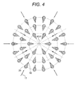
- Fig. 4 by the axial perpendicular sectional drawing of the burner 6 of the gas turbine combustor 2 of a section 37 shown in Fig. 2A and Fig. 3D , the arrangement method of the fuel nozzle 26 configuring the burner 6 of the gas turbine combustor 2 of the present embodiment is shown.
- the combustion air 17 flows from the outer periphery of the burner 6 toward the center 80 thereof by slipping through the gaps of the plurality of fuel nozzles 26.
- the edge 62 which is a projection formed at each rear edge of the fuel nozzles 26 configuring the burner 6 of the gas turbine combustor 2 of the present embodiment is arranged so as to be directed to the burner center in the downstream direction of the flow of the combustion air 17.
- the many fuel nozzles 26 configuring the burner 6 of the gas turbine combustor 2 and the many air holes 32 formed in the air hole plates 31 in pairs with these many fuel nozzles 26 are arranged coaxially in a plurality of rows outward radially from the center of the gas turbine combustor 2, for example, in three rows in Fig. 4 , though they are not restricted to three rows and may be arranged coaxially in four rows or more.
- the arrangement of the many air holes 32, if they are arranged circularly in the respective rows, is not restricted to arrangement on a concentric circle with the burner 6 and the center of each circle may be different from the burner center 80.
- the shape of the section of the fuel nozzle 26 on the upstream side of the flow is not restricted to the round shape as shown in Fig. 3C and Fig. 3D but may be the shape in which an edge similar to the edge 62 of the rear edge as shown in Fig. 5A is formed.
- the shapes of the section of the fuel nozzle 26 on the upstream side and the downstream side may be formed so as to become a shape smoothly connected or as shown in Fig. 5B , may be connected in a discontinuous shape in such a way that the inclined surfaces cross each other.
- the shape of the edge 62 in which the rear edge of the fuel nozzle 26 becomes a projection projected outward is optimum, though as shown in Fig. 5C , if the projection is shaped so that a width 63 of the projection of the fuel nozzle 26 for the flow on the axial perpendicular section is slowly reduced in the downstream direction, the separating of the flow is suppressed at its minimum, so that the shape of the projection at the rear edge of the fuel nozzle 26 is not restricted to an edge shape and may form a curvature.
- the recirculation region 61 becomes smaller than the recirculation region generated behind the circular section shown in Fig. 3A and Fig. 3B , so that the pressure loss can be reduced.
- Figs. 3C, 3D , 5A, 5B, 5C, and 5D the structure of the projection formed at the rear edge of the fuel nozzle 26 capable of reducing the pressure loss is shown, though as for the nozzle 26 of the gas turbine combustor 2, the projections formed at the rear edge of the fuel nozzle 26 may have all the same shape and the projections formed at the rear edge of the fuel nozzle 26 may be arranged in combination with a plurality of different shapes.
- the fuel nozzle 26 in the aforementioned structure with the projection formed at the rear edge is used, thus the flow around the fuel nozzle 26 is adjusted and unsteady hydrodynamic force acting on the fuel nozzles 26 caused by the separating of the flow is suppressed and the reliability of the structure of the gas turbine combustor 2 is improved.
- a gas turbine combustor capable of reducing the pressure loss without increasing the NOx emission can be realized.
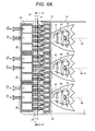
- Fig. 6A shows the axial cross sectional view of the gas turbine combustor 2 of the second embodiment and Fig. 6B shows the front view of the gas turbine combustor 2 shown in Fig. 6A viewed from the downstream side of the combustion chamber 5.
- one central burner 35 is arranged on the inner peripheral side which is the center of the gas turbine combustor 2, and on the outer periphery thereof, a plurality of outer peripheral burners 36 (for example, six burners) are arranged, and in combination with each other, one multi-burner 34 is structured.
- the structure of the multi-burner 34 as shown in Figs. 6A and 6B is used, thus the fuel system is pluralized such as 51 to 54, and with the change of the gas turbine load, the gas turbine combustor 2 can cope flexibly, and depending on the number of combinations, a gas turbine combustor different in the capacity per each can can be provided comparatively easily.
- the combustion air 17 flows in from the outer periphery of the multi-burner 34, slips through the gaps of the plurality of fuel nozzles 26 of the outer peripheral burners 36 and the gaps of the plurality of outer peripheral burners 36 and furthermore the gaps of the plurality of fuel nozzles 26 of the central burner 35, flows toward the combustor center 81, and flows into the air holes 32 of the plurality of outer peripheral burners 36 and the central burner 35.
- any of the shapes of the fuel nozzle 26 shown in the gas turbine combustor 2 of the first embodiment is acceptable and fuel nozzles in combination of some of the shapes may be installed.
- Fig. 7 by the axial perpendicular sectional drawing of the multi-burner 34 on the section 38 of the gas turbine combustor 2 shown in Fig. 6A , the outline of the arrangement of the fuel nozzles 26 of the present embodiment is shown.
- the center 80 of the central burner 35 of the gas turbine combustor 2 coincides with the center 81 of the gas turbine combustor 2, so that the edge 62 which is the projection at the rear edge of the fuel nozzle 26 is arranged so as to be directed to the center 81 of the burner in the flow direction of the combustion air flow 17.
- the center 80 thereof and the center 81 of the gas turbine combustor 2 do not coincide with each other and the combustion air 17, as shown in Fig. 7 , flows toward the center 81 of the gas turbine combustor 2 instead of the center 80 of the burner 36.
- the fuel nozzles 26 of the burner 6 positioned on the outer periphery of the gas turbine combustor 2, as shown in Fig. 7 , are arranged so that all edges 62 on the downstream side of the combustion air flow 17 are directed to the center 81 of the gas turbine combustor 2 instead of the burner center 80.
- the gas turbine combustor 2 of the present embodiment similarly to the single burner 6, even in the multi-burner 34, the separating of the flow behind the fuel nozzles 26 is suppressed and the pressure loss can be reduced. In addition, the flow around the fuel nozzles 26 is adjusted, thus the unsteady hydrodynamic force acting on the fuel nozzles 26 caused by the separating of the flow is suppressed and the reliability of the structure of the gas turbine combustor 2 is improved.
- the reduction of the pressure loss can be realized without increasing the NOx emission.
- a gas turbine combustor capable of reducing the pressure loss without increasing the NOx emission can be realized.
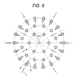
- Fig. 8 shows the arrangement method of the fuel nozzles 26 in the gas turbine combustor 2 of the third embodiment.
- the fuel nozzles 26 are arranged coaxially in a plurality of circular rows outward radially from the center of the gas turbine combustor, as for the flow rate of the combustion air 17 flowing around the fuel nozzles 26, the combustion air 17 flowing around the fuel nozzles 26 arranged on the outer periphery side is higher in the flow rate than that of the fuel nozzles 26 arranged on the inner periphery side.
- a fuel nozzle 26 positioned on a more outer periphery side has a larger recirculation flow formed behind it and the pressure loss associated with it is increased.
- the pressure loss reduction effect due to changing of the shape thereof to the shape of the edge 62 which is the shape of the projection at the rear edge of the fuel nozzle 26 shown in the gas turbine combustor 2 of the first embodiment becomes larger in the fuel nozzle 26 positioned on the outer periphery side than in the fuel nozzle 26 positioned on the inner periphery side.
- the shape change of the fuel nozzles 26 is not restricted to the outermost periphery and within the range with the increase permitted, on a priority basis from the outermost periphery, the shape of the fuel nozzles 26 on a plurality of peripheries can be changed.
- the number of fuel nozzles 26 whose shape is changed is restricted, and thereby the pressure loss reduction can be realized while suppressing the increase in the machining costs.
- a gas turbine combustor capable of reducing the pressure loss without increasing the NOx emission can be realized.
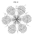
- Fig. 9 shows the arrangement method of the fuel nozzles 26 in the gas turbine combustor 2 of the fourth embodiment.
- the third embodiment showed the arrangement method of the fuel nozzles 26 in the gas turbine combustor 2 configured by one burner 6, and this method is for reducing the pressure loss while suppressing the increase in the machining costs in association with the shape change of the fuel nozzles 26.
- the arrangement method of the fuel nozzles 26 in the gas turbine combustor 2 of the present embodiment even in the gas turbine combustor for forming one multi-burner 34 in combination with a plurality of burners which is shown in the gas turbine combustor 2 of the second embodiment, the arrangement method of the fuel nozzles 26 capable of obtaining the similar effects to the gas turbine combustor 2 of the third embodiment is shown.
- the flow rate of the combustion air flowing around the fuel nozzles 26 becomes higher as the combustion air is separated from the combustor center 81, so that as the fuel nozzles 26 are separated from the combustor center 81, the recirculation flow formed behind it becomes larger and the pressure loss in association with it also becomes larger. Therefore, the shape thereof is changed to the shape of the fuel nozzles 26 shown in the gas turbine combustor 2 of the first embodiment, and thereby the pressure loss reduction effect becomes higher.
- a circle 82 having a radius of R with the combustor center 81 as the center is defined and only the fuel nozzles 26 whose centers are positioned outside the circle 82 are changed to the shape of the fuel nozzles 26 shown in the gas turbine combustor 2 of the first embodiment, and thereby the number of nozzles whose shape will be changed is restricted, and by suppressing the increase in the machining costs of the fuel nozzles 26, the pressure loss reduction effect can be maximized.
- the radius R of the circle 82 is determined by the changeable number of fuel nozzles which is calculated from the allowable increase in the machining costs or the required magnitude of pressure loss reduction.
- the gas turbine combustor 2 of the present embodiment even in the gas turbine combustor for forming one multi-burner in combination with a plurality of burners, the number of nozzles for changing the shape thereof is restricted, thus the pressure loss reduction can be realized while suppressing the increase in the machining costs.
- a gas turbine combustor capable of reducing the pressure loss without increasing the NOx emission can be realized.
- the structure of the fuel nozzle 26 of the gas turbine combustor 2 capable of suppressing the separating of the flow of the combustion air behind the fuel nozzle 26, reducing the pressure loss of the gas turbine combustor, and inserting the tip of the fuel nozzle 26 into the air hole 32 formed in the air plate 31 is shown.
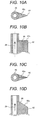
- Figs. 10A to 10F are drawings showing the shape of the fuel nozzle 26 of the gas turbine combustor 2 of the present embodiment.
- a structure of intending mixing enhancement of fuel and air in the air hole 32 formed in the air plate 31 and inserting the tip of the fuel nozzle 26 into the air hole 32 may be considered.
- the maximum width of the section of the fuel nozzle 26 becomes larger than the diameter of the air hole 32 and the fuel nozzle 26 may not be inserted into the air hole 32.
- the shape of the fuel nozzle 26 is formed so as to be a cylindrical shape with the section of the tip of the fuel nozzle 26 formed circularly, thereby allowing the tip of the fuel nozzle 26 to be inserted into the air hole 32 while reducing the pressure loss due to separating of the flow of combustion air is reduced.
- the shape of the fuel nozzle 26 of the gas turbine combustor 2 of the present embodiment forms the continuous portions 62a, 62b between the base and the tip for continuously changing smoothly to the cylindrical tip of the fuel nozzle 26 from the shape of the edge 62 which is the projection formed at the base of the fuel nozzle 26, thus the turbulence of the flow generated in the discontinuous portion can be suppressed.
- the separating of the flow of the combustion air 17 behind the fuel nozzle 26 is suppressed, and the pressure loss of the gas turbine combustor is reduced, and the insertion of the tip of the fuel nozzle 26 into the air hole 32 can be realized.
- a gas turbine combustor capable of reducing the pressure loss without increasing the NOx emission can be realized.
Landscapes
- Engineering & Computer Science (AREA)
- Chemical & Material Sciences (AREA)
- Combustion & Propulsion (AREA)
- Mechanical Engineering (AREA)
- General Engineering & Computer Science (AREA)
Abstract
The combustor (2) further comprises a combustion chamber (5) for mixing fuel injected from the fuel nozzles configuring the burner and air injected from the air holes (32) and burning the mixed fuel.
Description
- The present invention relates to a gas turbine combustor.
- From a viewpoint of environment protection, the gas turbine combustor is required for a further reduction of the NOx emission. As a measure for reduction of the NOx emission of the gas turbine combustor, a premixing combustor may be cited, though in this case, a flashback is worried that is a phenomenon in which a flame may enter the premixing combustor and damages the combustor.
- Japanese Patent Laid-open No.
2003-148734 - Japanese Patent Laid-open No.
2003-148734 - The gas turbine combustor is required to be operated stably under wide operation conditions from ignition to full load and reduce the NOx emission.
- In the gas turbine combustor disclosed in
Patent Literature 1, the multi-burner structure with a plurality of burners arranged and the mixing enhancement structure by fuel nozzles are disclosed, though a problem arises that when combustion air flows in the space wherein a plurality of fuel nozzles are lined on the upstream side of the air hole plates of the burners, a pressure loss due to separating of the flow generated behind the fuel nozzles is caused. - The pressure loss in the gas turbine combustor is related to an efficiency reduction of the entire gas turbine, so that to increase the efficiency of the gas turbine, it is necessary to reduce the pressure loss in the gas turbine combustor.
- An object of the present invention is to provide a gas turbine combustor capable of reducing the pressure loss of the gas turbine combustor without increasing the NOx emission.
- A gas turbine combustor of the present invention comprising a burner including a plurality of fuel nozzles for injecting fuel, an air hole plates positioned on a downstream side of the fuel nozzles and configured by each of the fuel nozzles and a plurality of air holes arranged in pairs with each of the fuel nozzles, and a combustion chamber for mixing fuel injected from the fuel nozzles configuring the burners and air injected from the air holes and injecting and burning the mixed fuel, characterized in that,
each of the fuel nozzles configuring the burners is provided with a projection in which a part of an outer edge of a section of the fuel nozzle is protruded outward; the projection is arranged so as to be directed toward a center of the gas turbine combustor; and the projection of the fuel nozzle is positioned on a downstream side of a flow of combustion air flowing around each of the fuel nozzles. - According to the present invention, a gas turbine combustor capable of reducing the pressure loss of the gas turbine combustor without increasing the NOx emission can be realized.
-
- {
Fig. 1} Fig. 1 is a plant system diagram showing the rough structure of the gas turbine plant to which the gas turbine combustor in the first embodiment of the present invention is applied. - {
Fig. 2A} Fig. 2A is an axial cross sectional view of the gas turbine combustor in the first embodiment of the present invention. - {
Fig. 2B} Fig. 2B is a front view of the gas turbine combustor in the first embodiment of the present invention shown inFig. 2A viewed from the downstream side of the combustion chamber. - {
Fig. 3A} Fig. 3A is a cross sectional view of a fuel nozzle showing the flow of the combustion air around the fuel nozzle of a conventional embodiment. - {
Fig. 3B} Fig. 3B is an axial cross sectional view of the fuel nozzle showing the shape of the fuel nozzle in a conventional embodiment shown inFig. 3A and the flow of the fuel flow flowing through the fuel nozzle. - {
Fig. 3C} Fig. 3C is a cross sectional view of a fuel nozzle showing the shape of a fuel nozzle of one aspect of an embodiment of the gas turbine combustor in the first embodiment of the present invention and the flow of the combustion air around it. - {
Fig. 3D} Fig. 3D is an axial cross sectional view of the fuel nozzle showing the shape of the fuel nozzle of the gas turbine combustor in the first embodiment of the present invention shown inFig. 3C , and the flow of the fuel flow flowing through the fuel nozzle. - {
Fig. 4} Fig. 4 is an arrangement diagram of the fuel nozzle showing the arrangement method of the fuel nozzle by the axial perpendicular section of the gas turbine combustor including the fuel nozzle in the first embodiment of the present invention. - {
Fig. 5A} Fig. 5A is a cross sectional view of the fuel nozzle showing the sectional shape of one aspect of an embodiment in the axial perpendicular direction of the fuel nozzle in the first embodiment of the present invention. - {
Fig. 5B} Fig. 5B is a cross sectional view of the fuel nozzle showing the sectional shape of another aspect of an embodiment in the axial perpendicular direction of the fuel nozzle in the first embodiment of the present invention. - {
Fig. 5C} Fig. 5C is a cross sectional view of the fuel nozzle showing the sectional shape of still another aspect of an embodiment in the axial perpendicular direction of the fuel nozzle in the first embodiment of the present invention. - {
Fig. 5D} Fig. 5D is a cross sectional view of the fuel nozzle showing the sectional shape of a further aspect of an embodiment in the axial perpendicular direction of the fuel nozzle in the first embodiment of the present invention. - {
Fig. 6A} Fig. 6A is an axial cross sectional view of the gas turbine combustor in the second embodiment of the present invention. - {
Fig. 6B} Fig. 6B is a front view of the gas turbine combustor in the second embodiment of the present invention shown inFig. 6A viewed from the downstream side of the combustion chamber. - {
Fig. 7} Fig. 7 is an arrangement diagram of the fuel nozzle showing the arrangement method of the fuel nozzle by the axial perpendicular section of the gas turbine combustor in the second embodiment of the present invention. - {
Fig. 8} Fig. 8 is an arrangement diagram of the fuel nozzle showing the arrangement method of the fuel nozzle in the third embodiment of the present invention. - {
Fig. 9} Fig. 9 is an arrangement diagram of the fuel nozzle showing the arrangement method of the fuel nozzle in the fourth embodiment of the present invention. - {
Fig. 10A} Fig. 10A is a cross sectional view of the fuel nozzle showing the shape of the fuel nozzle of one aspect of an embodiment in the fifth embodiment of the present invention. - {
Fig. 10B} Fig. 10B is an axial cross sectional view of the fuel nozzle in the fifth embodiment of the present invention shown inFig. 10A . - {
Fig. 10C} Fig. 10C is a cross sectional view of the fuel nozzle showing the shape of the fuel nozzle of another aspect of an embodiment in the fifth embodiment of the present invention. - {
Fig. 10D} Fig. 10D is an axial cross sectional view of the fuel nozzle in the fifth embodiment of the present invention shown inFig. 10C . - {
Fig. 10E} Fig. 10E is a cross sectional view of the fuel nozzle showing the shape of the fuel nozzle of still another aspect of an embodiment in the fifth embodiment of the present invention and the flow of the combustion air around it. - {
Fig. 10F} Fig. 10F is an axial cross sectional view of the fuel nozzle in the fifth embodiment of the present invention shown inFig. 10E . - The gas turbine combustor which is an embodiment of the present invention will be explained below by referring to the drawings.
- The gas turbine combustor which is the first embodiment of the present invention will be explained by referring to
Figs. 1 ,2A ,2B ,3C ,3D ,4 , and5 . -
Fig. 1 is the plant system diagram showing the rough structure of the gas turbine plant to which the gas turbine combustor in the first embodiment of the present invention is applied. - In the gas turbine plant shown in
Fig. 1 , the power generation gas turbine includes acompressor 1 for pressuringsuction air 15 to generate high-pressure air 16, a combustor 2 for burning the high-pressure air 16 generated by thecompressor 1 andgas fuel 50 to generate high-temperature combustion gas 18, aturbine 3 driven by the high-temperature combustion gas 18 generated by the gas turbine combustor 2, a generator 8 driven by theturbine 3 and generating electric power, and ashaft 7 for integrally connecting thecompressor 1, theturbine 3, and the generator 8. - And, the gas turbine combustor 2 is stored inside a
casing 4. Further, the gas turbine combustor 2 includes aburner 6 on the top thereof and an almostcylindrical liner 10 for separating the high-pressure air and the combustion gas inside the combustor 2 on the downstream side of theburner 6. - On the outer periphery of the
liner 10, aflow sleeve 11 as an outer peripheral wall forming an air flow path through which the high-pressure air flows down is arranged. Theflow sleeve 11 is larger in diameter than theliner 10 and is arranged cylindrically in an almost concentric circle with theliner 10. - Further, on the downstream side of the
liner 10, atransition piece 12 for leading the high-temperature combustion gas 18 generated in acombustion chamber 5 of the gas turbine combustor 2 is arranged. Further, on the outer periphery side of thetransition piece 12, aflow sleeve 13 is arranged. - The
suction air 15, after compressed by thecompressor 1, becomes the high-pressure air 16 and at the gas turbine rated load, becomes high temperature of 400°C or higher depending on the pressure ratio. - The high-
pressure air 16, after filled in thecasing 4, flows into the space between thetransition piece 12 and theflow sleeve 13 and cools thetransition piece 12 by a convection cooling from the outer wall surface. - Furthermore, the high-
pressure air 16, via the circular flow path formed between theflow sleeve 11 and theliner 10, flows toward the top of the gas turbine combustor 2. The high-pressure air 16, in the middle of the flow, is used for the convection cooling of theliner 10. - Further, a part of the high-
pressure air 16 is injected from many cooling holes provided in theliner 10 into theliner 10 along the inner wall surface thereof to form a cooling air film and protects and cools theliner 10 from the high-temperature combustion gas 18. - Among the high-
pressure air 16,residual combustion air 17 which is not used to cool theliner 10 flows into thecombustion chamber 5 frommany air holes 32 provided inair hole plates 31 positioned on the wall surface of thecombustion chamber 5 on the upstream side. - The
combustion air 17 flowing from themany air holes 32 into theliner 10 is burned together with the fuel injected fromfuel nozzles 26 in thecombustion chamber 5 and generates the high-temperature combustion gas 18. - The high-
temperature combustion gas 18 is fed to theturbine 3 via thetransition piece 12. The high-temperature combustion gas 18 is discharged after driving theturbine 3 and becomesexhaust gas 19. - The driving force obtained by the
turbine 3 is transmitted to thecompressor 1 and the generator 8 via theshaft 7. A part of the driving force obtained by theturbine 3 drives thecompressor 1, pressurizes air, and generates high-pressure air. Further, another part of the driving force obtained by theturbine 3 rotates the generator 8 to generate electric power. - The
burner 6 installed on the top of the gas turbine combustor 2 includes a plurality of fuel systems offuel systems fuel systems flow control valves fuel systems flow control valves gas turbine plant 9 is controlled. - Further, on the upstream side branching to the plurality of
fuel systems fuel cutoff valve 20 for cutting off the fuel is installed. -
Fig. 2A shows the axial cross sectional view of the gas turbine combustor 2 in the first embodiment andFig. 2B shows the front view of the gas turbine combustor 2 viewed from the downstream side of thecombustion chamber 5. - The gas turbine combustor 2 in the present embodiment is configured by one
burner 6 and theburner 6 is configured bymany fuel nozzles 26, afuel nozzle header 24 for distributing the fuel to themany fuel nozzles 26, and theair hole plates 31 where themany air holes 32 with air and fuel passing through are arranged in one-to-one correspondence with thefuel nozzles 26. - The fuel nozzles 26 and the air holes 32 formed in the
air hole plates 31 are arranged circularly on three rows of concentric circles around acenter axis 80 of theburner 6. Thecombustion air 17 flows in from the outer periphery of theburner 6, by slipping through the gaps of the plurality offuel nozzles 26 and flowing toward theburner center 80, flows into the air holes 32 formed in theair hole plates 31. - In the air holes 32 of the
air hole plates 31, thecombustion air 17 and afuel jet stream 27 are mixed and the mixed gas is fed to thecombustion chamber 5. Further, the air holes 32 of the burner are formed so as to be inclined to the axial center of thecombustion chamber 5, thus aswirl flow 40 is formed on the downstream side of theburner 6, and by arecirculation flow 41 generated by theswirl flow 40, aflame 42 is formed. - The gas turbine combustor 2 of this embodiment is configured by one
burner 6, so that thecenter axis 80 of theburner 6 and a center axis 81 of the gas turbine combustor 2 coincide with each other. - Here, the shape of the
fuel nozzles 26 configuring theburner 6 of the gas turbine combustor 2 in the present embodiment will be shown. -
Fig. 3A and Fig. 3B are the drawings showing the flow of thecombustion air 17 around thefuel nozzle 26 when the cross sectional shape of thefuel nozzle 26 configuring theburner 6 of the gas turbine combustor 2 is circular similarly to the fuel nozzle of the conventional embodiment, andFig. 3C and Fig. 3D are the drawings showing the shape of thefuel nozzle 26 of one aspect of an embodiment configuring theburner 6 of the gas turbine combustor 2 in the first embodiment of the present invention and the flow of the combustion air around it. - As shown in
Fig. 3A and Fig. 3B , in the case of thefuel nozzle 26 of the conventional embodiment having a circular cross sectional shape, thecombustion air 17 flowing around thefuel nozzle 26, since the flow is separated behind it, arecirculation flow 61 is formed, and this occurs in a plurality of fuel nozzles, leading to a pressure loss of the gas turbine combustor. - Therefore, in the gas turbine combustor 2 of the present embodiment shown in
Fig. 3C and Fig. 3D , the shape of thefuel nozzle 26 configuring theburner 6 is formed so that a part of the outer peripheral side of the section of thefuel nozzle 26 is protruded outward to form anedge 62 of a projection, and theedge 62 of thefuel nozzle 26 is arranged so as to be positioned on the downstream side of thecombustion air 17 flowing around thefuel nozzle 26. - And, the
edge 62 of the projection protruded outside thefuel nozzle 26 is arranged toward the downstream side of the flow of thecombustion air 17, thus the flow of thecombustion air 17 around thefuel nozzle 26 is adjusted, so that the formation of a recirculation flow due to separating is suppressed and a reduction of the pressure loss of the gas turbine combustor 2 can be realized. - In
Fig. 4 , by the axial perpendicular sectional drawing of theburner 6 of the gas turbine combustor 2 of asection 37 shown inFig. 2A andFig. 3D , the arrangement method of thefuel nozzle 26 configuring theburner 6 of the gas turbine combustor 2 of the present embodiment is shown. - As shown in
Fig. 2A andFig. 4 , in the space between theair hole plates 32 and thefuel nozzle header 24, thecombustion air 17 flows from the outer periphery of theburner 6 toward thecenter 80 thereof by slipping through the gaps of the plurality offuel nozzles 26. - The
edge 62 which is a projection formed at each rear edge of thefuel nozzles 26 configuring theburner 6 of the gas turbine combustor 2 of the present embodiment is arranged so as to be directed to the burner center in the downstream direction of the flow of thecombustion air 17. - In
Figs. 2A, 2B , and4 , themany fuel nozzles 26 configuring theburner 6 of the gas turbine combustor 2 and themany air holes 32 formed in theair hole plates 31 in pairs with thesemany fuel nozzles 26 are arranged coaxially in a plurality of rows outward radially from the center of the gas turbine combustor 2, for example, in three rows inFig. 4 , though they are not restricted to three rows and may be arranged coaxially in four rows or more. - Further, the arrangement of the
many air holes 32, if they are arranged circularly in the respective rows, is not restricted to arrangement on a concentric circle with theburner 6 and the center of each circle may be different from theburner center 80. - Further, if the separating of the combustion air flow behind each
fuel nozzle 26 can be suppressed, the shape of the section of thefuel nozzle 26 on the upstream side of the flow is not restricted to the round shape as shown inFig. 3C and Fig. 3D but may be the shape in which an edge similar to theedge 62 of the rear edge as shown inFig. 5A is formed. - Further, with respect to the flow in the section shape of the
fuel nozzle 26, the shapes of the section of thefuel nozzle 26 on the upstream side and the downstream side, as shown inFig. 5A , may be formed so as to become a shape smoothly connected or as shown inFig. 5B , may be connected in a discontinuous shape in such a way that the inclined surfaces cross each other. - To suppress the separating of the flow of the combustion air behind the
fuel nozzle 26 and reduce the pressure loss, the shape of theedge 62 in which the rear edge of thefuel nozzle 26 becomes a projection projected outward is optimum, though as shown inFig. 5C , if the projection is shaped so that awidth 63 of the projection of thefuel nozzle 26 for the flow on the axial perpendicular section is slowly reduced in the downstream direction, the separating of the flow is suppressed at its minimum, so that the shape of the projection at the rear edge of thefuel nozzle 26 is not restricted to an edge shape and may form a curvature. - Further, as shown in
Fig. 5D , for the shape of the projection of thefuel nozzle 26, even if the rear edge of the edge portion is plane, therecirculation region 61 becomes smaller than the recirculation region generated behind the circular section shown inFig. 3A and Fig. 3B , so that the pressure loss can be reduced. - In
Figs. 3C, 3D ,5A, 5B, 5C, and 5D , the structure of the projection formed at the rear edge of thefuel nozzle 26 capable of reducing the pressure loss is shown, though as for thenozzle 26 of the gas turbine combustor 2, the projections formed at the rear edge of thefuel nozzle 26 may have all the same shape and the projections formed at the rear edge of thefuel nozzle 26 may be arranged in combination with a plurality of different shapes. - For the
burner 6 of the gas turbine combustor 2 in the present embodiment, thefuel nozzle 26 in the aforementioned structure with the projection formed at the rear edge is used, thus the flow around thefuel nozzle 26 is adjusted and unsteady hydrodynamic force acting on thefuel nozzles 26 caused by the separating of the flow is suppressed and the reliability of the structure of the gas turbine combustor 2 is improved. - Further, on the downstream side of the pairs of the focused
fuel nozzle 26 and theair hole 32 formed in theair hole plate 31 to be focused, that is, turbulence of thecombustion air 17 flowing into the pairs of thefuel nozzle 26 closer to the center of theburner 6 and theair hole 32 is reduced, so that the flow-in rate of the combustion air into theair hole 32 is unified, and the local fuel air ratio in thecombustion chamber 5 of the gas turbine combustor 2 becomes uniform, thus the NOx emission is reduced. - As explained above, according to the present embodiment, a gas turbine combustor capable of reducing the pressure loss without increasing the NOx emission can be realized.
- Next, the gas turbine combustor 2 which is the second embodiment of the present invention will be explained by referring to
Figs. 6A ,6B , and7 . - In the gas turbine combustor 2 of the second embodiment, the explanation of the structure and operation effects common to the gas turbine combustor 2 of the first embodiment is omitted and only the different portions will be explained below.
-
Fig. 6A shows the axial cross sectional view of the gas turbine combustor 2 of the second embodiment andFig. 6B shows the front view of the gas turbine combustor 2 shown inFig. 6A viewed from the downstream side of thecombustion chamber 5. - In the gas turbine combustor 2 of the present embodiment shown in
Figs. 6A and6B , as for theburner 6 of the gas turbine combustor 2 of the first embodiment shown inFigs. 2A and 2B , onecentral burner 35 is arranged on the inner peripheral side which is the center of the gas turbine combustor 2, and on the outer periphery thereof, a plurality of outer peripheral burners 36 (for example, six burners) are arranged, and in combination with each other, onemulti-burner 34 is structured. - In the gas turbine combustor 2 of the present embodiment, the structure of the multi-burner 34 as shown in
Figs. 6A and6B is used, thus the fuel system is pluralized such as 51 to 54, and with the change of the gas turbine load, the gas turbine combustor 2 can cope flexibly, and depending on the number of combinations, a gas turbine combustor different in the capacity per each can can be provided comparatively easily. - Even in the
multi-burner 34 of the gas turbine combustor 2 shown in the present embodiment, thecombustion air 17 flows in from the outer periphery of the multi-burner 34, slips through the gaps of the plurality offuel nozzles 26 of the outerperipheral burners 36 and the gaps of the plurality of outerperipheral burners 36 and furthermore the gaps of the plurality offuel nozzles 26 of thecentral burner 35, flows toward the combustor center 81, and flows into the air holes 32 of the plurality of outerperipheral burners 36 and thecentral burner 35. - As a
fuel nozzle 26 in the gas turbine combustor 2 of the present embodiment, any of the shapes of thefuel nozzle 26 shown in the gas turbine combustor 2 of the first embodiment is acceptable and fuel nozzles in combination of some of the shapes may be installed. - In
Fig. 7 , by the axial perpendicular sectional drawing of the multi-burner 34 on thesection 38 of the gas turbine combustor 2 shown inFig. 6A , the outline of the arrangement of thefuel nozzles 26 of the present embodiment is shown. - In the case of the structure of the multi-burner 34 in the gas turbine combustor 2 of the present embodiment, the
center 80 of thecentral burner 35 of the gas turbine combustor 2 coincides with the center 81 of the gas turbine combustor 2, so that theedge 62 which is the projection at the rear edge of thefuel nozzle 26 is arranged so as to be directed to the center 81 of the burner in the flow direction of thecombustion air flow 17. - Namely, it is the same arrangement method as that of the
fuel nozzles 26 in the gas turbine combustor 2 of the first embodiment shown inFig. 4 . However, as for the outerperipheral burner 36 among the plurality of burners configuring the gas turbine combustor 2 of the present embodiment, thecenter 80 thereof and the center 81 of the gas turbine combustor 2 do not coincide with each other and thecombustion air 17, as shown inFig. 7 , flows toward the center 81 of the gas turbine combustor 2 instead of thecenter 80 of theburner 36. - Therefore, the
fuel nozzles 26 of theburner 6 positioned on the outer periphery of the gas turbine combustor 2, as shown inFig. 7 , are arranged so that all edges 62 on the downstream side of thecombustion air flow 17 are directed to the center 81 of the gas turbine combustor 2 instead of theburner center 80. - According to the gas turbine combustor 2 of the present embodiment, similarly to the
single burner 6, even in the multi-burner 34, the separating of the flow behind thefuel nozzles 26 is suppressed and the pressure loss can be reduced. In addition, the flow around thefuel nozzles 26 is adjusted, thus the unsteady hydrodynamic force acting on thefuel nozzles 26 caused by the separating of the flow is suppressed and the reliability of the structure of the gas turbine combustor 2 is improved. - Further, on the downstream side of the pairs of the
fuel nozzle 26 and theair hole 32 to be focused, that is, turbulence of thecombustion air 17 flowing into the pairs of thefuel nozzle 26 and theair hole 32 closer to the combustor center 81 is reduced, so that the flow-in rate of thecombustion air 17 into theair hole 32 is unified, and the local fuel air ratio in thecombustion chamber 5 of the gas turbine combustor 2 becomes uniform, thus the NOx emission is reduced. - Therefore, according to the present embodiment, even in a gas turbine combustor in which a multi-burner is configured by combining a plurality of burners, the reduction of the pressure loss can be realized without increasing the NOx emission.
- As explained above, according to the present embodiment, a gas turbine combustor capable of reducing the pressure loss without increasing the NOx emission can be realized.
- Next, the gas turbine combustor 2 which is the third embodiment of the present invention will be explained by referring to
Fig. 8 . - In the gas turbine combustor 2 of the third embodiment shown in
Fig. 8 , the explanation of the structure and operation effects common to the gas turbine combustor 2 of the first embodiment is omitted and only the different portions will be explained below. -
Fig. 8 shows the arrangement method of thefuel nozzles 26 in the gas turbine combustor 2 of the third embodiment. Like theburner 6 shown in the gas turbine combustor 2 of the first embodiment, when thefuel nozzles 26 are arranged coaxially in a plurality of circular rows outward radially from the center of the gas turbine combustor, as for the flow rate of thecombustion air 17 flowing around thefuel nozzles 26, thecombustion air 17 flowing around thefuel nozzles 26 arranged on the outer periphery side is higher in the flow rate than that of thefuel nozzles 26 arranged on the inner periphery side. - Namely, as for the
fuel nozzles 26 arranged in the plurality of circular rows, afuel nozzle 26 positioned on a more outer periphery side has a larger recirculation flow formed behind it and the pressure loss associated with it is increased. - Therefore, the pressure loss reduction effect due to changing of the shape thereof to the shape of the
edge 62 which is the shape of the projection at the rear edge of thefuel nozzle 26 shown in the gas turbine combustor 2 of the first embodiment becomes larger in thefuel nozzle 26 positioned on the outer periphery side than in thefuel nozzle 26 positioned on the inner periphery side. - Meanwhile, in association with the shape change of the projection at the rear edge of each
fuel nozzle 26, there are possibilities that the machining costs of thefuel nozzles 26 and the gas turbine combustor itself may increase. To suppress the increase in the machining costs, a method of reducing the number offuel nozzles 26 whose shape is to be changed may be considered. - In that case, as shown in
Fig. 8 , among thefuel nozzles 26 arranged in a plurality of circular rows, only thefuel nozzle 26 on the outermost periphery is changed to the exact shape of theedge 62 which is the projection at the rear edge of thefuel nozzle 26 of the gas turbine combustor 2 of the first embodiment, and thereby the pressure loss reduction effect can be maximized by suppressing the increase in the machining costs. - Even when the fuel nozzles of the gas turbine combustor 2 are arrayed in four or more circular rows, only the
fuel nozzle 26 on the outermost periphery thereof is changed to the exact shape of theedge 62 which is the shape of the projection shown in thefuel nozzle 26 of the gas turbine combustor 2 of the first embodiment, and thereby the effect similar to the case of thefuel nozzles 26, arranged in three rows, of the gas turbine combustor 2 can be obtained. - Further, if the increase in the machining costs is permitted to a certain extent, the shape change of the
fuel nozzles 26 is not restricted to the outermost periphery and within the range with the increase permitted, on a priority basis from the outermost periphery, the shape of thefuel nozzles 26 on a plurality of peripheries can be changed. - As mentioned above, according to the gas turbine combustor 2 of the present embodiment, the number of
fuel nozzles 26 whose shape is changed is restricted, and thereby the pressure loss reduction can be realized while suppressing the increase in the machining costs. - As explained above, according to the present embodiment, a gas turbine combustor capable of reducing the pressure loss without increasing the NOx emission can be realized.
- Next, the gas turbine combustor 2 which is the fourth embodiment of the present invention will be explained by referring to
Fig. 9 . - In the gas turbine combustor 2 of the fourth embodiment shown in
Fig. 9 , the explanation of the structure and operation effects common to the gas turbine combustor 2 of the first embodiment is omitted and only the different portions will be explained below. -
Fig. 9 shows the arrangement method of thefuel nozzles 26 in the gas turbine combustor 2 of the fourth embodiment. The third embodiment showed the arrangement method of thefuel nozzles 26 in the gas turbine combustor 2 configured by oneburner 6, and this method is for reducing the pressure loss while suppressing the increase in the machining costs in association with the shape change of thefuel nozzles 26. By contrast, in the arrangement method of thefuel nozzles 26 in the gas turbine combustor 2 of the present embodiment, even in the gas turbine combustor for forming onemulti-burner 34 in combination with a plurality of burners which is shown in the gas turbine combustor 2 of the second embodiment, the arrangement method of thefuel nozzles 26 capable of obtaining the similar effects to the gas turbine combustor 2 of the third embodiment is shown. - Even in the gas turbine combustor 2 of the present embodiment for forming one
multi-burner 34 in combination with a plurality of burners, the flow rate of the combustion air flowing around thefuel nozzles 26 becomes higher as the combustion air is separated from the combustor center 81, so that as thefuel nozzles 26 are separated from the combustor center 81, the recirculation flow formed behind it becomes larger and the pressure loss in association with it also becomes larger. Therefore, the shape thereof is changed to the shape of thefuel nozzles 26 shown in the gas turbine combustor 2 of the first embodiment, and thereby the pressure loss reduction effect becomes higher. - Therefore, a
circle 82 having a radius of R with the combustor center 81 as the center is defined and only thefuel nozzles 26 whose centers are positioned outside thecircle 82 are changed to the shape of thefuel nozzles 26 shown in the gas turbine combustor 2 of the first embodiment, and thereby the number of nozzles whose shape will be changed is restricted, and by suppressing the increase in the machining costs of thefuel nozzles 26, the pressure loss reduction effect can be maximized. - The radius R of the
circle 82 is determined by the changeable number of fuel nozzles which is calculated from the allowable increase in the machining costs or the required magnitude of pressure loss reduction. - As mentioned above, according to the gas turbine combustor 2 of the present embodiment, even in the gas turbine combustor for forming one multi-burner in combination with a plurality of burners, the number of nozzles for changing the shape thereof is restricted, thus the pressure loss reduction can be realized while suppressing the increase in the machining costs.
- As explained above, according to the present embodiment, a gas turbine combustor capable of reducing the pressure loss without increasing the NOx emission can be realized.
- Next, the gas turbine combustor 2 which is the fifth embodiment of the present invention will be explained by referring to
Figs. 10A to 10F . - In the gas turbine combustor 2 of the fifth embodiment shown in
Figs. 10A to 10F , the explanation of the structure and operation effects common to the gas turbine combustor 2 of the first embodiment is omitted and only the different portions will be explained below. - In the gas turbine combustor 2 of the present embodiment, the structure of the
fuel nozzle 26 of the gas turbine combustor 2 capable of suppressing the separating of the flow of the combustion air behind thefuel nozzle 26, reducing the pressure loss of the gas turbine combustor, and inserting the tip of thefuel nozzle 26 into theair hole 32 formed in theair plate 31 is shown. -
Figs. 10A to 10F are drawings showing the shape of thefuel nozzle 26 of the gas turbine combustor 2 of the present embodiment. - As shown in
Figs. 10A to 10F , in thefuel nozzle 26 of the gas turbine combustor 2 of the present embodiment, a structure of intending mixing enhancement of fuel and air in theair hole 32 formed in theair plate 31 and inserting the tip of thefuel nozzle 26 into theair hole 32 may be considered. - However, in the shape of the
fuel nozzle 26 of the gas turbine combustor 2 shown in the first embodiment, the maximum width of the section of thefuel nozzle 26 becomes larger than the diameter of theair hole 32 and thefuel nozzle 26 may not be inserted into theair hole 32. - Therefore, in the
fuel nozzle 26 of the gas turbine combustor 2 of the present embodiment, as shown inFigs. 10A and 10B , the shape of thefuel nozzle 26, from the shape of theedge 62 which is the projection in which the section of the base of thefuel nozzle 26 in the axial direction is projected on the rear edge side, is formed so as to be a cylindrical shape with the section of the tip of thefuel nozzle 26 formed circularly, thereby allowing the tip of thefuel nozzle 26 to be inserted into theair hole 32 while reducing the pressure loss due to separating of the flow of combustion air is reduced. - Further, in the shape of the
fuel nozzle 26 of the gas turbine combustor 2 of the present embodiment shown inFigs. 10A and 10B , since the shape of the base and the shape of the tip are changed at thediscontinuous portion 62c between the base and the tip discontinuously, there are possibilities that turbulence generated due to separating of the flow in the discontinuous portion may affect the flow-in of thecombustion air 17 into theair hole 32. - Therefore, as shown in
Figs. 10C, 10D ,10E, and 10F , the shape of thefuel nozzle 26 of the gas turbine combustor 2 of the present embodiment forms thecontinuous portions fuel nozzle 26 from the shape of theedge 62 which is the projection formed at the base of thefuel nozzle 26, thus the turbulence of the flow generated in the discontinuous portion can be suppressed. - By the
aforementioned fuel nozzle 26 of the gas turbine combustor 2 of the present embodiment, the separating of the flow of thecombustion air 17 behind thefuel nozzle 26 is suppressed, and the pressure loss of the gas turbine combustor is reduced, and the insertion of the tip of thefuel nozzle 26 into theair hole 32 can be realized. - As explained above, according to the present embodiment, a gas turbine combustor capable of reducing the pressure loss without increasing the NOx emission can be realized.
Claims (8)
- A gas turbine combustor comprising a burner including a plurality of fuel nozzles for injecting fuel, an air hole plates positioned on a downstream side of the fuel nozzles and configured by each of the fuel nozzles and a plurality of air holes arranged in pairs with each of the fuel nozzles, and a combustion chamber for mixing fuel injected from the fuel nozzles configuring the burners and air injected from the air holes and injecting and burning the mixed fuel, characterized in that,
each of the fuel nozzles configuring the burners is provided with a projection in which a part of an outer edge of a section of the fuel nozzle is protruded outward; the projection is arranged so as to be directed toward a center of the gas turbine combustor; and the projection of the fuel nozzle is positioned on a downstream side of a flow of combustion air flowing around each of the fuel nozzles. - The gas turbine combustor according to Claim 1, wherein:the projection in which a part of the outer edge of the section of the fuel nozzle is protruded outward is formed in an edge shape.
- The gas turbine combustor according to Claim 1, wherein:the projection in which a part of the outer edge of the section of the fuel nozzle is protruded outward is formed in a shape that a width of the projection of an axial perpendicular section of the fuel nozzle with respect to the flow of the combustion air is reduced in a downstream direction of the flow of the combustion air.
- The gas turbine combustor according to Claim 1, wherein:the fuel nozzles are arranged in combination with a fuel nozzle having projection in which a part of the outer edge of the section of the fuel nozzle is protruded outward to form in an edge shape and another fuel nozzle to form in a shape that a width of a projection of an axial perpendicular section of the fuel nozzle with respect to the flow of the combustion air is reduced in the downstream direction of the combustion air.
- The gas turbine combustor according to Claim 1, wherein:a multi-burner is structured a burner including a central burner installed on an inner periphery side which is a center of the gas turbine combustor and a plurality of outer peripheral burners installed on an outer periphery side of the central burner which is the outer periphery side of the gas turbine combustor.
- The gas turbine combustor according to Claim 1, wherein:the plurality of fuel nozzles configuring the burners and the plurality of air holes formed in air hole plates positioned on a downstream side of the fuel nozzles are arranged in pairs with each of the fuel nozzles, and arranged coaxially in a plurality of rows outward radially from the center of the gas turbine combustor, andthe fuel nozzles installed in a part of rows of the plurality of rows concentrically arranged outward radially from the center of the gas turbine combustor is provided with a projection in which a part of the outer edge of the section of the fuel nozzle is protruded outward.
- The gas turbine combustor according to any one of Claims 1 to 6, wherein:the fuel nozzle configuring the burner is shaped to form a projection in which a part of the outer edge of the section of the fuel nozzle is protruded outward at a base of the fuel nozzle, and form cylindrically at a tip of the fuel nozzle.
- The gas turbine combustor according to Claim 7, wherein:the fuel nozzle configuring the burners is provided with a continuous portion of a sectional shape in an axial direction thereof where the shape is changed continuously and smoothly between the nozzle projection at the base of an outer fuel nozzle and the cylindrical tip of the fuel nozzle.
Applications Claiming Priority (1)
| Application Number | Priority Date | Filing Date | Title |
|---|---|---|---|
| JP2013234675A JP6239943B2 (en) | 2013-11-13 | 2013-11-13 | Gas turbine combustor |
Publications (2)
| Publication Number | Publication Date |
|---|---|
| EP2873923A1 true EP2873923A1 (en) | 2015-05-20 |
| EP2873923B1 EP2873923B1 (en) | 2017-10-25 |
Family
ID=51868915
Family Applications (1)
| Application Number | Title | Priority Date | Filing Date |
|---|---|---|---|
| EP14192874.7A Active EP2873923B1 (en) | 2013-11-13 | 2014-11-12 | Gas turbine combustor |
Country Status (4)
| Country | Link |
|---|---|
| US (1) | US9765971B2 (en) |
| EP (1) | EP2873923B1 (en) |
| JP (1) | JP6239943B2 (en) |
| CN (1) | CN104633708B (en) |
Families Citing this family (4)
| Publication number | Priority date | Publication date | Assignee | Title |
|---|---|---|---|---|
| JP6210810B2 (en) * | 2013-09-20 | 2017-10-11 | 三菱日立パワーシステムズ株式会社 | Dual fuel fired gas turbine combustor |
| JP6484546B2 (en) * | 2015-11-13 | 2019-03-13 | 三菱日立パワーシステムズ株式会社 | Gas turbine combustor |
| US11493161B2 (en) * | 2017-07-19 | 2022-11-08 | Parker-Hannifin Corporation | Dual-fuel multi-port connector |
| US10948188B2 (en) * | 2018-12-12 | 2021-03-16 | Solar Turbines Incorporated | Fuel injector with perforated plate |
Citations (4)
| Publication number | Priority date | Publication date | Assignee | Title |
|---|---|---|---|---|
| JP2003148734A (en) | 2001-08-29 | 2003-05-21 | Hitachi Ltd | Gas turbine combustor and method of operating gas turbine combustor |
| EP2161501A2 (en) * | 2008-09-03 | 2010-03-10 | Hitachi Ltd. | Combustor, fuel nozzle and method of fuel supplying |
| EP2481986A2 (en) * | 2011-01-27 | 2012-08-01 | Hitachi Ltd. | Gas turbine combustor |
| EP2527741A2 (en) * | 2011-05-24 | 2012-11-28 | General Electric Company | System and method for flow control in gas turbine engine |
Family Cites Families (14)
| Publication number | Priority date | Publication date | Assignee | Title |
|---|---|---|---|---|
| EP0059490B1 (en) * | 1981-03-04 | 1984-12-12 | BBC Aktiengesellschaft Brown, Boveri & Cie. | Annular combustion chamber with an annular burner for gas turbines |
| US5647215A (en) * | 1995-11-07 | 1997-07-15 | Westinghouse Electric Corporation | Gas turbine combustor with turbulence enhanced mixing fuel injectors |
| US6928823B2 (en) | 2001-08-29 | 2005-08-16 | Hitachi, Ltd. | Gas turbine combustor and operating method thereof |
| US6813889B2 (en) | 2001-08-29 | 2004-11-09 | Hitachi, Ltd. | Gas turbine combustor and operating method thereof |
| JP3940705B2 (en) * | 2003-06-19 | 2007-07-04 | 株式会社日立製作所 | Gas turbine combustor and fuel supply method thereof |
| JP4894295B2 (en) * | 2006-02-28 | 2012-03-14 | 株式会社日立製作所 | Combustion device, combustion method of combustion device, and modification method of combustion device |
| US20090111063A1 (en) | 2007-10-29 | 2009-04-30 | General Electric Company | Lean premixed, radial inflow, multi-annular staged nozzle, can-annular, dual-fuel combustor |
| JP4918509B2 (en) | 2008-02-15 | 2012-04-18 | 三菱重工業株式会社 | Combustor |
| US20100293956A1 (en) * | 2009-05-21 | 2010-11-25 | General Electric Company | Turbine fuel nozzle having premixer with auxiliary vane |
| JP2011038710A (en) * | 2009-08-12 | 2011-02-24 | Hitachi Ltd | Gas turbine combustor |
| JP2011058775A (en) | 2009-09-14 | 2011-03-24 | Hitachi Ltd | Gas turbine combustor |
| US8365532B2 (en) * | 2009-09-30 | 2013-02-05 | General Electric Company | Apparatus and method for a gas turbine nozzle |
| US9557050B2 (en) * | 2010-07-30 | 2017-01-31 | General Electric Company | Fuel nozzle and assembly and gas turbine comprising the same |
| JP5630424B2 (en) * | 2011-11-21 | 2014-11-26 | 三菱日立パワーシステムズ株式会社 | Gas turbine combustor |
-
2013
- 2013-11-13 JP JP2013234675A patent/JP6239943B2/en active Active
-
2014
- 2014-11-11 CN CN201410641900.4A patent/CN104633708B/en active Active
- 2014-11-12 US US14/539,157 patent/US9765971B2/en active Active
- 2014-11-12 EP EP14192874.7A patent/EP2873923B1/en active Active
Patent Citations (4)
| Publication number | Priority date | Publication date | Assignee | Title |
|---|---|---|---|---|
| JP2003148734A (en) | 2001-08-29 | 2003-05-21 | Hitachi Ltd | Gas turbine combustor and method of operating gas turbine combustor |
| EP2161501A2 (en) * | 2008-09-03 | 2010-03-10 | Hitachi Ltd. | Combustor, fuel nozzle and method of fuel supplying |
| EP2481986A2 (en) * | 2011-01-27 | 2012-08-01 | Hitachi Ltd. | Gas turbine combustor |
| EP2527741A2 (en) * | 2011-05-24 | 2012-11-28 | General Electric Company | System and method for flow control in gas turbine engine |
Also Published As
| Publication number | Publication date |
|---|---|
| CN104633708B (en) | 2017-05-17 |
| JP2015094535A (en) | 2015-05-18 |
| EP2873923B1 (en) | 2017-10-25 |
| US20150128601A1 (en) | 2015-05-14 |
| JP6239943B2 (en) | 2017-11-29 |
| CN104633708A (en) | 2015-05-20 |
| US9765971B2 (en) | 2017-09-19 |
Similar Documents
| Publication | Publication Date | Title |
|---|---|---|
| JP6736284B2 (en) | Premix fuel nozzle assembly | |
| JP5948489B2 (en) | Gas turbine combustor | |
| JP5940227B2 (en) | Gas turbine combustor | |
| US8904798B2 (en) | Combustor | |
| JP5470662B2 (en) | Gas turbine combustor | |
| EP2620708B1 (en) | Gas turbine combustor and operating method thereof | |
| CN102538008B (en) | Gas turbine combustor and fuel supply method | |
| EP2873922B1 (en) | Gas turbine combustor | |
| US20200033006A1 (en) | Combustor nozzle, combustor, and gas turbine | |
| JP7245150B2 (en) | gas turbine combustor | |
| JP6849306B2 (en) | Premixed fuel nozzle assembly | |
| CN102345879A (en) | Fuel nozzle and assembly and gas turbine comprising the same | |
| JP5911387B2 (en) | Gas turbine combustor and gas turbine combustor operating method | |
| EP2873923B1 (en) | Gas turbine combustor | |
| KR20170107391A (en) | Axially staged fuel injector assembly mounting | |
| JP2014105886A (en) | Combustor | |
| JP2010133621A (en) | Gas-turbine combustion equipment | |
| JP6092007B2 (en) | Gas turbine combustor | |
| JP2011038710A (en) | Gas turbine combustor | |
| JP6068117B2 (en) | Combustor | |
| JP5331909B2 (en) | Combustor | |
| JP6326205B2 (en) | Fuel nozzle, combustor, and gas turbine | |
| JP6182395B2 (en) | Gas turbine combustor and control method thereof | |
| JP6159145B2 (en) | Combustor | |
| EP2629015A2 (en) | Outer fuel nozzle inlet flow conditioner interface to end cap |
Legal Events
| Date | Code | Title | Description |
|---|---|---|---|
| PUAI | Public reference made under article 153(3) epc to a published international application that has entered the european phase |
Free format text: ORIGINAL CODE: 0009012 |
|
| 17P | Request for examination filed |
Effective date: 20150327 |
|
| AK | Designated contracting states |
Kind code of ref document: A1 Designated state(s): AL AT BE BG CH CY CZ DE DK EE ES FI FR GB GR HR HU IE IS IT LI LT LU LV MC MK MT NL NO PL PT RO RS SE SI SK SM TR |
|
| AX | Request for extension of the european patent |
Extension state: BA ME |
|
| GRAP | Despatch of communication of intention to grant a patent |
Free format text: ORIGINAL CODE: EPIDOSNIGR1 |
|
| STAA | Information on the status of an ep patent application or granted ep patent |
Free format text: STATUS: GRANT OF PATENT IS INTENDED |
|
| RIC1 | Information provided on ipc code assigned before grant |
Ipc: F23R 3/28 20060101AFI20170622BHEP |
|
| INTG | Intention to grant announced |
Effective date: 20170707 |
|
| GRAS | Grant fee paid |
Free format text: ORIGINAL CODE: EPIDOSNIGR3 |
|
| GRAA | (expected) grant |
Free format text: ORIGINAL CODE: 0009210 |
|
| STAA | Information on the status of an ep patent application or granted ep patent |
Free format text: STATUS: THE PATENT HAS BEEN GRANTED |
|
| AK | Designated contracting states |
Kind code of ref document: B1 Designated state(s): AL AT BE BG CH CY CZ DE DK EE ES FI FR GB GR HR HU IE IS IT LI LT LU LV MC MK MT NL NO PL PT RO RS SE SI SK SM TR |
|
| REG | Reference to a national code |
Ref country code: GB Ref legal event code: FG4D |
|
| REG | Reference to a national code |
Ref country code: CH Ref legal event code: EP |
|
| REG | Reference to a national code |
Ref country code: AT Ref legal event code: REF Ref document number: 940286 Country of ref document: AT Kind code of ref document: T Effective date: 20171115 |
|
| REG | Reference to a national code |
Ref country code: FR Ref legal event code: PLFP Year of fee payment: 4 Ref country code: IE Ref legal event code: FG4D |
|
| REG | Reference to a national code |
Ref country code: DE Ref legal event code: R096 Ref document number: 602014016205 Country of ref document: DE |
|
| REG | Reference to a national code |
Ref country code: NL Ref legal event code: MP Effective date: 20171025 |
|
| REG | Reference to a national code |
Ref country code: LT Ref legal event code: MG4D |
|
| REG | Reference to a national code |
Ref country code: AT Ref legal event code: MK05 Ref document number: 940286 Country of ref document: AT Kind code of ref document: T Effective date: 20171025 |
|
| PG25 | Lapsed in a contracting state [announced via postgrant information from national office to epo] |
Ref country code: NL Free format text: LAPSE BECAUSE OF FAILURE TO SUBMIT A TRANSLATION OF THE DESCRIPTION OR TO PAY THE FEE WITHIN THE PRESCRIBED TIME-LIMIT Effective date: 20171025 |
|
| PG25 | Lapsed in a contracting state [announced via postgrant information from national office to epo] |
Ref country code: ES Free format text: LAPSE BECAUSE OF FAILURE TO SUBMIT A TRANSLATION OF THE DESCRIPTION OR TO PAY THE FEE WITHIN THE PRESCRIBED TIME-LIMIT Effective date: 20171025 Ref country code: LT Free format text: LAPSE BECAUSE OF FAILURE TO SUBMIT A TRANSLATION OF THE DESCRIPTION OR TO PAY THE FEE WITHIN THE PRESCRIBED TIME-LIMIT Effective date: 20171025 Ref country code: FI Free format text: LAPSE BECAUSE OF FAILURE TO SUBMIT A TRANSLATION OF THE DESCRIPTION OR TO PAY THE FEE WITHIN THE PRESCRIBED TIME-LIMIT Effective date: 20171025 Ref country code: NO Free format text: LAPSE BECAUSE OF FAILURE TO SUBMIT A TRANSLATION OF THE DESCRIPTION OR TO PAY THE FEE WITHIN THE PRESCRIBED TIME-LIMIT Effective date: 20180125 Ref country code: SE Free format text: LAPSE BECAUSE OF FAILURE TO SUBMIT A TRANSLATION OF THE DESCRIPTION OR TO PAY THE FEE WITHIN THE PRESCRIBED TIME-LIMIT Effective date: 20171025 |
|
| PG25 | Lapsed in a contracting state [announced via postgrant information from national office to epo] |
Ref country code: IS Free format text: LAPSE BECAUSE OF FAILURE TO SUBMIT A TRANSLATION OF THE DESCRIPTION OR TO PAY THE FEE WITHIN THE PRESCRIBED TIME-LIMIT Effective date: 20180225 Ref country code: GR Free format text: LAPSE BECAUSE OF FAILURE TO SUBMIT A TRANSLATION OF THE DESCRIPTION OR TO PAY THE FEE WITHIN THE PRESCRIBED TIME-LIMIT Effective date: 20180126 Ref country code: LV Free format text: LAPSE BECAUSE OF FAILURE TO SUBMIT A TRANSLATION OF THE DESCRIPTION OR TO PAY THE FEE WITHIN THE PRESCRIBED TIME-LIMIT Effective date: 20171025 Ref country code: HR Free format text: LAPSE BECAUSE OF FAILURE TO SUBMIT A TRANSLATION OF THE DESCRIPTION OR TO PAY THE FEE WITHIN THE PRESCRIBED TIME-LIMIT Effective date: 20171025 Ref country code: RS Free format text: LAPSE BECAUSE OF FAILURE TO SUBMIT A TRANSLATION OF THE DESCRIPTION OR TO PAY THE FEE WITHIN THE PRESCRIBED TIME-LIMIT Effective date: 20171025 Ref country code: AT Free format text: LAPSE BECAUSE OF FAILURE TO SUBMIT A TRANSLATION OF THE DESCRIPTION OR TO PAY THE FEE WITHIN THE PRESCRIBED TIME-LIMIT Effective date: 20171025 Ref country code: BG Free format text: LAPSE BECAUSE OF FAILURE TO SUBMIT A TRANSLATION OF THE DESCRIPTION OR TO PAY THE FEE WITHIN THE PRESCRIBED TIME-LIMIT Effective date: 20180125 |
|
| REG | Reference to a national code |
Ref country code: DE Ref legal event code: R097 Ref document number: 602014016205 Country of ref document: DE |
|
| PG25 | Lapsed in a contracting state [announced via postgrant information from national office to epo] |
Ref country code: CZ Free format text: LAPSE BECAUSE OF FAILURE TO SUBMIT A TRANSLATION OF THE DESCRIPTION OR TO PAY THE FEE WITHIN THE PRESCRIBED TIME-LIMIT Effective date: 20171025 Ref country code: MC Free format text: LAPSE BECAUSE OF FAILURE TO SUBMIT A TRANSLATION OF THE DESCRIPTION OR TO PAY THE FEE WITHIN THE PRESCRIBED TIME-LIMIT Effective date: 20171025 Ref country code: SK Free format text: LAPSE BECAUSE OF FAILURE TO SUBMIT A TRANSLATION OF THE DESCRIPTION OR TO PAY THE FEE WITHIN THE PRESCRIBED TIME-LIMIT Effective date: 20171025 Ref country code: LI Free format text: LAPSE BECAUSE OF NON-PAYMENT OF DUE FEES Effective date: 20171130 Ref country code: CH Free format text: LAPSE BECAUSE OF NON-PAYMENT OF DUE FEES Effective date: 20171130 Ref country code: DK Free format text: LAPSE BECAUSE OF FAILURE TO SUBMIT A TRANSLATION OF THE DESCRIPTION OR TO PAY THE FEE WITHIN THE PRESCRIBED TIME-LIMIT Effective date: 20171025 Ref country code: EE Free format text: LAPSE BECAUSE OF FAILURE TO SUBMIT A TRANSLATION OF THE DESCRIPTION OR TO PAY THE FEE WITHIN THE PRESCRIBED TIME-LIMIT Effective date: 20171025 Ref country code: CY Free format text: LAPSE BECAUSE OF FAILURE TO SUBMIT A TRANSLATION OF THE DESCRIPTION OR TO PAY THE FEE WITHIN THE PRESCRIBED TIME-LIMIT Effective date: 20171025 |
|
| PG25 | Lapsed in a contracting state [announced via postgrant information from national office to epo] |
Ref country code: IT Free format text: LAPSE BECAUSE OF FAILURE TO SUBMIT A TRANSLATION OF THE DESCRIPTION OR TO PAY THE FEE WITHIN THE PRESCRIBED TIME-LIMIT Effective date: 20171025 Ref country code: SM Free format text: LAPSE BECAUSE OF FAILURE TO SUBMIT A TRANSLATION OF THE DESCRIPTION OR TO PAY THE FEE WITHIN THE PRESCRIBED TIME-LIMIT Effective date: 20171025 Ref country code: LU Free format text: LAPSE BECAUSE OF NON-PAYMENT OF DUE FEES Effective date: 20171112 Ref country code: PL Free format text: LAPSE BECAUSE OF FAILURE TO SUBMIT A TRANSLATION OF THE DESCRIPTION OR TO PAY THE FEE WITHIN THE PRESCRIBED TIME-LIMIT Effective date: 20171025 |
|
| PLBE | No opposition filed within time limit |
Free format text: ORIGINAL CODE: 0009261 |
|
| REG | Reference to a national code |
Ref country code: BE Ref legal event code: MM Effective date: 20171130 |
|
| STAA | Information on the status of an ep patent application or granted ep patent |
Free format text: STATUS: NO OPPOSITION FILED WITHIN TIME LIMIT |
|
| REG | Reference to a national code |
Ref country code: IE Ref legal event code: MM4A |
|
| PG25 | Lapsed in a contracting state [announced via postgrant information from national office to epo] |
Ref country code: MT Free format text: LAPSE BECAUSE OF NON-PAYMENT OF DUE FEES Effective date: 20171112 |
|
| 26N | No opposition filed |
Effective date: 20180726 |
|
| PG25 | Lapsed in a contracting state [announced via postgrant information from national office to epo] |
Ref country code: IE Free format text: LAPSE BECAUSE OF NON-PAYMENT OF DUE FEES Effective date: 20171112 |
|
| PG25 | Lapsed in a contracting state [announced via postgrant information from national office to epo] |
Ref country code: SI Free format text: LAPSE BECAUSE OF FAILURE TO SUBMIT A TRANSLATION OF THE DESCRIPTION OR TO PAY THE FEE WITHIN THE PRESCRIBED TIME-LIMIT Effective date: 20171025 Ref country code: BE Free format text: LAPSE BECAUSE OF NON-PAYMENT OF DUE FEES Effective date: 20171130 |
|
| PG25 | Lapsed in a contracting state [announced via postgrant information from national office to epo] |
Ref country code: HU Free format text: LAPSE BECAUSE OF FAILURE TO SUBMIT A TRANSLATION OF THE DESCRIPTION OR TO PAY THE FEE WITHIN THE PRESCRIBED TIME-LIMIT; INVALID AB INITIO Effective date: 20141112 |
|
| PG25 | Lapsed in a contracting state [announced via postgrant information from national office to epo] |
Ref country code: RO Free format text: LAPSE BECAUSE OF FAILURE TO SUBMIT A TRANSLATION OF THE DESCRIPTION OR TO PAY THE FEE WITHIN THE PRESCRIBED TIME-LIMIT Effective date: 20171025 |
|
| PG25 | Lapsed in a contracting state [announced via postgrant information from national office to epo] |
Ref country code: MK Free format text: LAPSE BECAUSE OF FAILURE TO SUBMIT A TRANSLATION OF THE DESCRIPTION OR TO PAY THE FEE WITHIN THE PRESCRIBED TIME-LIMIT Effective date: 20171025 |
|
| PG25 | Lapsed in a contracting state [announced via postgrant information from national office to epo] |
Ref country code: TR Free format text: LAPSE BECAUSE OF FAILURE TO SUBMIT A TRANSLATION OF THE DESCRIPTION OR TO PAY THE FEE WITHIN THE PRESCRIBED TIME-LIMIT Effective date: 20171025 |
|
| PG25 | Lapsed in a contracting state [announced via postgrant information from national office to epo] |
Ref country code: PT Free format text: LAPSE BECAUSE OF FAILURE TO SUBMIT A TRANSLATION OF THE DESCRIPTION OR TO PAY THE FEE WITHIN THE PRESCRIBED TIME-LIMIT Effective date: 20171025 |
|
| PG25 | Lapsed in a contracting state [announced via postgrant information from national office to epo] |
Ref country code: AL Free format text: LAPSE BECAUSE OF FAILURE TO SUBMIT A TRANSLATION OF THE DESCRIPTION OR TO PAY THE FEE WITHIN THE PRESCRIBED TIME-LIMIT Effective date: 20171025 |
|
| REG | Reference to a national code |
Ref country code: DE Ref legal event code: R082 Ref document number: 602014016205 Country of ref document: DE Representative=s name: BEETZ & PARTNER MBB PATENTANWAELTE, DE Ref country code: DE Ref legal event code: R081 Ref document number: 602014016205 Country of ref document: DE Owner name: MITSUBISHI POWER, LTD., JP Free format text: FORMER OWNER: MITSUBISHI HITACHI POWER SYSTEMS, LTD., YOKOHAMA-SHI, KANAGAWA, JP |
|
| PGFP | Annual fee paid to national office [announced via postgrant information from national office to epo] |
Ref country code: FR Payment date: 20250930 Year of fee payment: 12 |
|
| PGFP | Annual fee paid to national office [announced via postgrant information from national office to epo] |
Ref country code: DE Payment date: 20250930 Year of fee payment: 12 |
|
| PGFP | Annual fee paid to national office [announced via postgrant information from national office to epo] |
Ref country code: GB Payment date: 20251001 Year of fee payment: 12 |