EP2873896B1 - Component seal - Google Patents
Component seal Download PDFInfo
- Publication number
- EP2873896B1 EP2873896B1 EP14003820.9A EP14003820A EP2873896B1 EP 2873896 B1 EP2873896 B1 EP 2873896B1 EP 14003820 A EP14003820 A EP 14003820A EP 2873896 B1 EP2873896 B1 EP 2873896B1
- Authority
- EP
- European Patent Office
- Prior art keywords
- elastomeric
- seal
- diameter
- seal according
- floating
- Prior art date
- Legal status (The legal status is an assumption and is not a legal conclusion. Google has not performed a legal analysis and makes no representation as to the accuracy of the status listed.)
- Active
Links
Images



Classifications
-
- F—MECHANICAL ENGINEERING; LIGHTING; HEATING; WEAPONS; BLASTING
- F16—ENGINEERING ELEMENTS AND UNITS; GENERAL MEASURES FOR PRODUCING AND MAINTAINING EFFECTIVE FUNCTIONING OF MACHINES OR INSTALLATIONS; THERMAL INSULATION IN GENERAL
- F16J—PISTONS; CYLINDERS; SEALINGS
- F16J15/00—Sealings
- F16J15/16—Sealings between relatively-moving surfaces
- F16J15/34—Sealings between relatively-moving surfaces with slip-ring pressed against a more or less radial face on one member
-
- F—MECHANICAL ENGINEERING; LIGHTING; HEATING; WEAPONS; BLASTING
- F16—ENGINEERING ELEMENTS AND UNITS; GENERAL MEASURES FOR PRODUCING AND MAINTAINING EFFECTIVE FUNCTIONING OF MACHINES OR INSTALLATIONS; THERMAL INSULATION IN GENERAL
- F16J—PISTONS; CYLINDERS; SEALINGS
- F16J15/00—Sealings
- F16J15/16—Sealings between relatively-moving surfaces
- F16J15/34—Sealings between relatively-moving surfaces with slip-ring pressed against a more or less radial face on one member
- F16J15/36—Sealings between relatively-moving surfaces with slip-ring pressed against a more or less radial face on one member connected by a diaphragm or bellow to the other member
-
- F—MECHANICAL ENGINEERING; LIGHTING; HEATING; WEAPONS; BLASTING
- F16—ENGINEERING ELEMENTS AND UNITS; GENERAL MEASURES FOR PRODUCING AND MAINTAINING EFFECTIVE FUNCTIONING OF MACHINES OR INSTALLATIONS; THERMAL INSULATION IN GENERAL
- F16J—PISTONS; CYLINDERS; SEALINGS
- F16J15/00—Sealings
- F16J15/16—Sealings between relatively-moving surfaces
- F16J15/34—Sealings between relatively-moving surfaces with slip-ring pressed against a more or less radial face on one member
- F16J15/3436—Pressing means
- F16J15/3452—Pressing means the pressing force resulting from the action of a spring
-
- F—MECHANICAL ENGINEERING; LIGHTING; HEATING; WEAPONS; BLASTING
- F16—ENGINEERING ELEMENTS AND UNITS; GENERAL MEASURES FOR PRODUCING AND MAINTAINING EFFECTIVE FUNCTIONING OF MACHINES OR INSTALLATIONS; THERMAL INSULATION IN GENERAL
- F16J—PISTONS; CYLINDERS; SEALINGS
- F16J15/00—Sealings
- F16J15/44—Free-space packings
- F16J15/441—Free-space packings with floating ring
Definitions
- the invention relates to mechanical seals, which are fitted to rotating equipment in virtually all types of industries.
- a mechanical seal comprises a "floating" component which is mounted axially movable around the rotary shaft of, for example, a pump or a “static” component which is axially fixed, typically being secured to a housing.
- the floating component has a flat annular end face, i.e. its seal face, directed towards a seal face of the static component.
- the floating component is urged towards the static component to close the seal faces together to form a sliding face seal, usually by means of one or more spring members.
- one of the floating and static components rotates; this component is therefore referred to as the rotary component.
- the other of the floating and static components does not rotate and is referred to as the stationary component. See e.g.
- FR-A-952 035 (Crane packing Ltd) Those seals whose floating component is rotary are described as rotary seals. If the floating component is stationary, the seal is referred to as a stationary seal. If the sliding seal between the rotary and stationary components are assembled and pre-set prior to despatch from the Mechanical seal manufacturing premises, the industry terminology for this is “cartridge seal”. If the rotary and stationary components are despatched individually (unassembled) from the Mechanical seal manufacturing premises, the industry terminology for this is "component seal”. This invention relates to a component seal which is used in applications where there is a large amount of contaminates in the product.
- the invention relates to a mechanical seal for providing a fluid-tight seal between relatively rotatable elements, the seal comprising;
- a mechanical seal comprising an elastomeric member, a spring biasing means, a longitudinally floating first member comprising a seal face, a longitudinally non-floating second member and a longitudinally floating third member (6); the elastomeric member being in sealing engagement with the first member, second member and third members; the spring biasing means being longitudinally positioned between the first member and the second member, one of the first member and the second member being provided with at least one protruding male portion and the other of the first member and the second member being provided with corresponding female portion into which the male portion locates, the profile of the elastomeric member comprising one or more convolutions which extend outwardly to allow the floating members to move in an axial direction, and a groove being provided on the outer surface of the second member to allow an inwardly protruding portion of the elastomeric member to engage therewith.
- the seal face is a separate component to the first member and is axially and radially retained by the first member thereby allowing it to be Centroidally loaded, different materials being fitted in a common first member and also reducing the complexity and size of the seal face which tends to be expensive exotic materials.
- the third member is in engagement with the first member providing a cavity in which the elastomeric member is retained.
- the groove on the outer surface of the third member in which resides an inwardly protruding portion of the elastomeric member to engage, ensures that the elastomeric bellows member does not move during the assembly of the third member.
- annular surface of the second member is larger in diameter than the third member thereby allowing axial engagement of the components and so limiting the level of axial movement that the third member can achieve during assembly improving fitment.
- the outermost surface of the third member is angled in such a way as to reduce the diameter of the area which is in closest proximity to the sealing face thereby improving fluid flow around the sealing faces aiding sealing performance.
- one or more scallops are located around the axis of the diameter thereby allowing the third member to be installed with the use of a tool and also potentially increasing fluid flow around the sealing faces.
- the inner diameter of the elastomeric member is smaller than the outer diameter of the second member thereby ensuring that the second member does not become detached from the elastomeric bellows during installation of the seal.
- annular groove resides in the first member and an elastomeric toroidal sealing member is located therein providing radially restrictive contact between the first and second members.
- the general principle of mechanical seals in accordance with the present invention may be used not only in the case where the shaft is a rotary member and the housing is the stationary member but also the reverse situation, that is to say, in which the shaft is stationary and the housing is rotary.
- the invention may be embodied in both rotary and stationary arrangements, cartridge and component seals with metallic components as well as non-metallic components.
- the invention 1 incorporates an elastomeric bellows member 2 which is radially disposed in operation between a shaft 3 and first, second and third members, 4, 5 and 6 respectively.
- the second member 5 squeezes the elastomeric bellows member 2, thereby providing a seal between the elastomeric bellows member 2, the second member 5 and the shaft member 3.
- the third member 6 squeezes the elastomeric bellows member 2 onto the first member 4 providing a seal between the members.
- a primary sealing face 7 resides in the first member 4 and is urged toward the second sealing face 8 via a plurality of springs 9 which reside in a plurality of cavities in the first member 4 and are compressed in operation between the cavities and the second member 5.
- One or more pins 10 are located in the second member 5 protruding into an opposing cavity in the first member 4 thereby providing axial drive between the shaft 3, bellows member 2, second member 5 and the first member 4.
- the second sealing face 8 is in sealing engagement with the pump housing 11 via a secondary elastomeric boot member 12.
- a tertiary elastomeric member 13 is located in a groove located on the inner diameter of the first member 4 providing radial alignment means between the first and second members, 4 and 5 respectively.
- the elastomeric bellows member 2 contains a convolution 14 between the outermost diameter of the second member 5 and the first and third member, 4 and 6 respectively, thereby providing an area for the elastomeric bellows member 2 to distort radially when the invention 1 is installed.
- the profile of the third member 6 is designed in such a way that a portion of its inner diameter is smaller than the outermost diameter of the first member 4 thereby limiting the extent that it can contact the elastomeric bellows member 2 when assembled.
- the profile of the third member 6 also contains an angled, or tapered, portion 15 that means that the diameter closest to the first sealing face 7 is reduced with respect to the other end.
- the profile of the elastomeric bellows member 2 contains an inwardly protruding portion 16 which locates into a groove 17 in the outer surface of the first member 4 to ensure the elastomeric bellows member 2 is interlockingly retained therein and will not detach from the first member 4 during assembly of the third member 6.
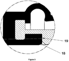
- the profile of the elastomeric bellows member 2 contains an outwardly protruding portion 18 which locates into a groove 19 in the inner diameter of the second member 5.
- the elastomeric bellows member 2 extends radially past the outer diameter of the second member 5 and axially along its outer most diameter. At this portion the diameter of the second member 5 reduces allowing the elastomeric bellows member to protrude inwardly creating an overlap between the components.
- one or more cutouts or scallops 20 are included in the angled portion 15 of the third member 6 thereby providing a flat surface for a fitting tool to engage with to aid assembly of the third member 6 onto the first member 4.
- These scallops which are axially located around the diameter of the third member 6 may also act as flow inducing sections mixing the product fluid near the sealing faces 7 and 8.
Landscapes
- Engineering & Computer Science (AREA)
- General Engineering & Computer Science (AREA)
- Mechanical Engineering (AREA)
- Mechanical Sealing (AREA)
Description
- The invention relates to mechanical seals, which are fitted to rotating equipment in virtually all types of industries.
- A mechanical seal comprises a "floating" component which is mounted axially movable around the rotary shaft of, for example, a pump or a "static" component which is axially fixed, typically being secured to a housing. The floating component has a flat annular end face, i.e. its seal face, directed towards a seal face of the static component. The floating component is urged towards the static component to close the seal faces together to form a sliding face seal, usually by means of one or more spring members. In use, one of the floating and static components rotates; this component is therefore referred to as the rotary component. The other of the floating and static components does not rotate and is referred to as the stationary component. See e.g.
FR-A-952 035
If the sliding seal between the rotary and stationary components are assembled and pre-set prior to despatch from the Mechanical seal manufacturing premises, the industry terminology for this is "cartridge seal". If the rotary and stationary components are despatched individually (unassembled) from the Mechanical seal manufacturing premises, the industry terminology for this is "component seal".
This invention relates to a component seal which is used in applications where there is a large amount of contaminates in the product. These contaminants can become entrenched between moving components in traditional designs of mechanical seals causing these components to "hang up" and so resulting in pre mature failure of the seal. One common method of stopping these contaminates becoming entrenched is to use a rubber component such as a bellows to create a seal between moving components. The limitation to these bellows is that they are either commonly used with a single spring component seals which create uneven face pressures or the bellows can become detached allowing contaminates to enter the bellows sealed area. - The invention relates to a mechanical seal for providing a fluid-tight seal between relatively rotatable elements, the seal comprising;
- A mechanical seal comprising an elastomeric member, a spring biasing means, a longitudinally floating first member comprising a seal face, a longitudinally non-floating second member and a longitudinally floating third member (6); the elastomeric member being in sealing engagement with the first member, second member and third members; the spring biasing means being longitudinally positioned between the first member and the second member, one of the first member and the second member being provided with at least one protruding male portion and the other of the first member and the second member being provided with corresponding female portion into which the male portion locates, the profile of the elastomeric member comprising one or more convolutions which extend outwardly to allow the floating members to move in an axial direction, and a groove being provided on the outer surface of the second member to allow an inwardly protruding portion of the elastomeric member to engage therewith.
- Preferably the seal face is a separate component to the first member and is axially and radially retained by the first member thereby allowing it to be Centroidally loaded, different materials being fitted in a common first member and also reducing the complexity and size of the seal face which tends to be expensive exotic materials.
- Preferably the third member is in engagement with the first member providing a cavity in which the elastomeric member is retained.
- The groove on the outer surface of the third member, in which resides an inwardly protruding portion of the elastomeric member to engage, ensures that the elastomeric bellows member does not move during the assembly of the third member.
- More preferably, wherein an annular surface of the second member is larger in diameter than the third member thereby allowing axial engagement of the components and so limiting the level of axial movement that the third member can achieve during assembly improving fitment.
- More preferably, the outermost surface of the third member is angled in such a way as to reduce the diameter of the area which is in closest proximity to the sealing face thereby improving fluid flow around the sealing faces aiding sealing performance.
- More preferably, one or more scallops are located around the axis of the diameter thereby allowing the third member to be installed with the use of a tool and also potentially increasing fluid flow around the sealing faces.
- Preferably, the inner diameter of the elastomeric member is smaller than the outer diameter of the second member thereby ensuring that the second member does not become detached from the elastomeric bellows during installation of the seal.
- Preferably, an annular groove resides in the first member and an elastomeric toroidal sealing member is located therein providing radially restrictive contact between the first and second members.
- The accompanying drawings are as follows:
-
Figure 1 is a sectional side elevation of a mechanical seal in accordance with a first preferred embodiment of the present invention; -
Figure 2 is a magnified sectional side elevation of the sealing section between the first, third and elastomeric bellows member of the embodiment ofFigure 1 ; -
Figure 3 is a magnified sectional side elevation of the sealing section between the second member and elastomeric bellows member of the embodiment ofFigure 1 ; -
Figure 4 is a front end elevation of the invention showing the scallop sections axially located around the diameter of the third member of the embodiment ofFigure 1 . - The invention will now be described, by way of examples only, with reference to the accompanying drawings.
- The general principle of mechanical seals in accordance with the present invention may be used not only in the case where the shaft is a rotary member and the housing is the stationary member but also the reverse situation, that is to say, in which the shaft is stationary and the housing is rotary.
- Furthermore, the invention may be embodied in both rotary and stationary arrangements, cartridge and component seals with metallic components as well as non-metallic components.
- Referring to
Figure 1 of the accompanying drawings, theinvention 1 incorporates an elastomeric bellows member 2 which is radially disposed in operation between ashaft 3 and first, second and third members, 4, 5 and 6 respectively. The second member 5 squeezes the elastomeric bellows member 2, thereby providing a seal between the elastomeric bellows member 2, the second member 5 and theshaft member 3. The third member 6 squeezes the elastomeric bellows member 2 onto the first member 4 providing a seal between the members. A primary sealing face 7 resides in the first member 4 and is urged toward the second sealing face 8 via a plurality of springs 9 which reside in a plurality of cavities in the first member 4 and are compressed in operation between the cavities and the second member 5. One ormore pins 10 are located in the second member 5 protruding into an opposing cavity in the first member 4 thereby providing axial drive between theshaft 3, bellows member 2, second member 5 and the first member 4. The second sealing face 8 is in sealing engagement with thepump housing 11 via a secondaryelastomeric boot member 12. A tertiaryelastomeric member 13 is located in a groove located on the inner diameter of the first member 4 providing radial alignment means between the first and second members, 4 and 5 respectively. - The elastomeric bellows member 2 contains a
convolution 14 between the outermost diameter of the second member 5 and the first and third member, 4 and 6 respectively, thereby providing an area for the elastomeric bellows member 2 to distort radially when theinvention 1 is installed. The profile of the third member 6 is designed in such a way that a portion of its inner diameter is smaller than the outermost diameter of the first member 4 thereby limiting the extent that it can contact the elastomeric bellows member 2 when assembled. The profile of the third member 6 also contains an angled, or tapered,portion 15 that means that the diameter closest to the first sealing face 7 is reduced with respect to the other end. - Referring to
Figure 2 of the accompanying drawings, the profile of the elastomeric bellows member 2 contains an inwardly protrudingportion 16 which locates into agroove 17 in the outer surface of the first member 4 to ensure the elastomeric bellows member 2 is interlockingly retained therein and will not detach from the first member 4 during assembly of the third member 6. - Referring to
Figure 3 of the accompanying drawings, the profile of the elastomeric bellows member 2 contains an outwardly protrudingportion 18 which locates into agroove 19 in the inner diameter of the second member 5. The elastomeric bellows member 2 extends radially past the outer diameter of the second member 5 and axially along its outer most diameter. At this portion the diameter of the second member 5 reduces allowing the elastomeric bellows member to protrude inwardly creating an overlap between the components. These features thereby axially constrain the elastomeric bellows member 2 to the second member 5 during assembly of theinvention 1 to theshaft 3. - Referring to
Figure 1 and4 one or more cutouts orscallops 20 are included in theangled portion 15 of the third member 6 thereby providing a flat surface for a fitting tool to engage with to aid assembly of the third member 6 onto the first member 4. These scallops which are axially located around the diameter of the third member 6 may also act as flow inducing sections mixing the product fluid near the sealing faces 7 and 8.
Claims (8)
- A mechanical seal comprising an elastomeric member (2), a spring biasing means (9), a longitudinally floating first member (4) comprising a seal face, a longitudinally non-floating second member (5) and a longitudinally floating third member (6); the elastomeric member (2) being in sealing engagement with the first member (4), second member (5) and third (6) members; the spring biasing means (9) being longitudinally positioned between the first member (4) and the second member (5), one of the first member (4) and the second member (6) being provided with at least one protruding male portion (10)and the other of the first member and the second member being provided with corresponding female portion into which the male portion locates, characterised in that the profile of the elastomeric member (2) comprising one or more convolutions (14) which extend outwardly to allow the floating (4,6) to move in an axial direction, and a groove (17) being provided on the outer surface of the second member (5) to allow an inwardly protruding portion (16) of the elastomeric member (2) to engage therewith.
- A seal according to claim 1, wherein said seal face is a separate component (7) from the first member (4) and is axially and radially retained by the first member (4).
- A seal according to claim 1 or claim 2, wherein the third member (6) is in engagement with the first member (4) and forms a cavity in which the elastomeric member is retained.
- A seal according to any preceding claim, wherein a surface of the second member (5) is annular and that annular surface is larger in diameter than the diameter of the third member, (6) thereby allowing axial engagement of the two components.
- A seal according to any preceding claim, wherein the outermost surface (15) of the third (6) is angled in such a way as to reduce the diameter of the region which is in closest proximity to the sealing face.
- A seal according to any preceding claim, wherein one or more scallops are located around the axis of the diameter of the third member (6).
- A seal according to any preceding claim, wherein the inner diameter of the elastomeric member (2) is smaller than the outer diameter of the second member (5).
- A seal according to any preceding claim, wherein the first member (4) is provided with an annular groove and an elastomeric toroidal sealing member (13) is located therein.
Applications Claiming Priority (1)
| Application Number | Priority Date | Filing Date | Title |
|---|---|---|---|
| GB1320063.9A GB2520281B (en) | 2013-11-13 | 2013-11-13 | Component seal |
Publications (2)
| Publication Number | Publication Date |
|---|---|
| EP2873896A1 EP2873896A1 (en) | 2015-05-20 |
| EP2873896B1 true EP2873896B1 (en) | 2018-02-21 |
Family
ID=49818580
Family Applications (1)
| Application Number | Title | Priority Date | Filing Date |
|---|---|---|---|
| EP14003820.9A Active EP2873896B1 (en) | 2013-11-13 | 2014-11-13 | Component seal |
Country Status (3)
| Country | Link |
|---|---|
| US (1) | US9810325B2 (en) |
| EP (1) | EP2873896B1 (en) |
| GB (1) | GB2520281B (en) |
Families Citing this family (2)
| Publication number | Priority date | Publication date | Assignee | Title |
|---|---|---|---|---|
| GB201210611D0 (en) * | 2012-06-14 | 2012-08-01 | Aes Eng Ltd | Hygienic seal & system |
| US12203575B2 (en) * | 2022-01-26 | 2025-01-21 | Deublin Company, LLC | Rotary union having pressure sleeve |
Family Cites Families (12)
| Publication number | Priority date | Publication date | Assignee | Title |
|---|---|---|---|---|
| GB648814A (en) * | 1946-09-03 | 1951-01-10 | Crane Packing Ltd | Improvements relating to fluid-tight sealing means between rotary and non-rotary members |
| US2728591A (en) * | 1952-12-22 | 1955-12-27 | Crane Packing Co | Rotary mechanical seal |
| US2892642A (en) * | 1955-08-18 | 1959-06-30 | Crane Packing Co | Rotary mechanical seal |
| US4434988A (en) * | 1982-10-28 | 1984-03-06 | Gits Brothers Mfg. Co. | Shaft seal |
| US4483545A (en) * | 1983-02-24 | 1984-11-20 | Gray Tool Company | Fire resistant connections and double ribbed sealing means therefor |
| DE3338019A1 (en) * | 1983-10-19 | 1985-05-02 | Feodor Burgmann Dichtungswerke Gmbh & Co, 8190 Wolfratshausen | Rotating mechanical seal with an elastomeric seal bellows |
| US5639098A (en) * | 1994-10-03 | 1997-06-17 | Duramax, Inc. | Adjustable seal for propeller drive shaft |
| US5558343A (en) * | 1995-12-26 | 1996-09-24 | General Motors Corporation | Water pump seal assembly |
| GB9606815D0 (en) * | 1996-03-30 | 1996-06-05 | Crane John Uk Ltd | Mechanical face seals |
| GB0214857D0 (en) * | 2002-06-26 | 2002-08-07 | Aes Eng Ltd | Mechanical seal drive and coupling device |
| US7344356B1 (en) * | 2004-09-15 | 2008-03-18 | Wood Group Esp, Inc. | Mechanical seal with bellows seating alignment |
| US20080048400A1 (en) * | 2006-08-28 | 2008-02-28 | Freudenberg-Nok General Partnership | Unitized seal with integral flanged sleeve |
-
2013
- 2013-11-13 GB GB1320063.9A patent/GB2520281B/en active Active
-
2014
- 2014-11-13 EP EP14003820.9A patent/EP2873896B1/en active Active
- 2014-11-13 US US14/540,920 patent/US9810325B2/en active Active
Non-Patent Citations (1)
| Title |
|---|
| None * |
Also Published As
| Publication number | Publication date |
|---|---|
| GB2520281B (en) | 2016-04-13 |
| US9810325B2 (en) | 2017-11-07 |
| GB201320063D0 (en) | 2013-12-25 |
| GB2520281A (en) | 2015-05-20 |
| EP2873896A1 (en) | 2015-05-20 |
| US20150130141A1 (en) | 2015-05-14 |
Similar Documents
| Publication | Publication Date | Title |
|---|---|---|
| CN107250631B (en) | Double-piston effect lip seal base assembly | |
| WO2018105505A1 (en) | Sliding component | |
| US9915349B2 (en) | Dynamically non contacting seal | |
| US10077843B2 (en) | Division type mechanical seal | |
| EP2663730B1 (en) | Flowline divertor seal with spring-energized lips | |
| US9638327B1 (en) | Radial shaft seal | |
| US9810325B2 (en) | Component seal | |
| CN205244496U (en) | Hydraulic system and check valve | |
| US9746080B2 (en) | High pressure seal assembly for a moveable shaft | |
| EP2783141B1 (en) | Component seal | |
| US9915350B2 (en) | P04TU drive ring | |
| US9097347B2 (en) | Carbon seal assembly | |
| GB2561961A (en) | Mechanical seal | |
| CN108350949A (en) | Shaft coupling and pump | |
| KR20190117391A (en) | Sealing mechanism and apparatus having the sealing mechanism | |
| CN102066818A (en) | Contaminant sealing device | |
| CA2901034C (en) | Apparatus for excluding particle contaminants from a gas lift off mechanical seal | |
| WO2014012496A1 (en) | Sealing device in a valve and a valve with the same | |
| CN104343986A (en) | Sealing assembly | |
| US10443769B2 (en) | Pivot joint | |
| US20120319359A1 (en) | Sealing apparatus | |
| WO2013186516A1 (en) | Hygienic seal system | |
| WO2019145770A1 (en) | Valve assembly with a sealing group | |
| US2711914A (en) | Multi-disk floating contact mechanical shaft seal | |
| CN112074676B (en) | Sealing means |
Legal Events
| Date | Code | Title | Description |
|---|---|---|---|
| PUAI | Public reference made under article 153(3) epc to a published international application that has entered the european phase |
Free format text: ORIGINAL CODE: 0009012 |
|
| 17P | Request for examination filed |
Effective date: 20141113 |
|
| AK | Designated contracting states |
Kind code of ref document: A1 Designated state(s): AL AT BE BG CH CY CZ DE DK EE ES FI FR GB GR HR HU IE IS IT LI LT LU LV MC MK MT NL NO PL PT RO RS SE SI SK SM TR |
|
| AX | Request for extension of the european patent |
Extension state: BA ME |
|
| R17P | Request for examination filed (corrected) |
Effective date: 20151120 |
|
| RBV | Designated contracting states (corrected) |
Designated state(s): AL AT BE BG CH CY CZ DE DK EE ES FI FR GB GR HR HU IE IS IT LI LT LU LV MC MK MT NL NO PL PT RO RS SE SI SK SM TR |
|
| 17Q | First examination report despatched |
Effective date: 20161017 |
|
| GRAP | Despatch of communication of intention to grant a patent |
Free format text: ORIGINAL CODE: EPIDOSNIGR1 |
|
| INTG | Intention to grant announced |
Effective date: 20170530 |
|
| GRAS | Grant fee paid |
Free format text: ORIGINAL CODE: EPIDOSNIGR3 |
|
| GRAA | (expected) grant |
Free format text: ORIGINAL CODE: 0009210 |
|
| AK | Designated contracting states |
Kind code of ref document: B1 Designated state(s): AL AT BE BG CH CY CZ DE DK EE ES FI FR GB GR HR HU IE IS IT LI LT LU LV MC MK MT NL NO PL PT RO RS SE SI SK SM TR |
|
| REG | Reference to a national code |
Ref country code: GB Ref legal event code: FG4D |
|
| REG | Reference to a national code |
Ref country code: CH Ref legal event code: EP |
|
| REG | Reference to a national code |
Ref country code: AT Ref legal event code: REF Ref document number: 972117 Country of ref document: AT Kind code of ref document: T Effective date: 20180315 |
|
| REG | Reference to a national code |
Ref country code: IE Ref legal event code: FG4D |
|
| REG | Reference to a national code |
Ref country code: DE Ref legal event code: R096 Ref document number: 602014021086 Country of ref document: DE |
|
| REG | Reference to a national code |
Ref country code: NL Ref legal event code: MP Effective date: 20180221 |
|
| REG | Reference to a national code |
Ref country code: LT Ref legal event code: MG4D |
|
| REG | Reference to a national code |
Ref country code: AT Ref legal event code: MK05 Ref document number: 972117 Country of ref document: AT Kind code of ref document: T Effective date: 20180221 |
|
| PG25 | Lapsed in a contracting state [announced via postgrant information from national office to epo] |
Ref country code: NL Free format text: LAPSE BECAUSE OF FAILURE TO SUBMIT A TRANSLATION OF THE DESCRIPTION OR TO PAY THE FEE WITHIN THE PRESCRIBED TIME-LIMIT Effective date: 20180221 Ref country code: HR Free format text: LAPSE BECAUSE OF FAILURE TO SUBMIT A TRANSLATION OF THE DESCRIPTION OR TO PAY THE FEE WITHIN THE PRESCRIBED TIME-LIMIT Effective date: 20180221 Ref country code: ES Free format text: LAPSE BECAUSE OF FAILURE TO SUBMIT A TRANSLATION OF THE DESCRIPTION OR TO PAY THE FEE WITHIN THE PRESCRIBED TIME-LIMIT Effective date: 20180221 Ref country code: FI Free format text: LAPSE BECAUSE OF FAILURE TO SUBMIT A TRANSLATION OF THE DESCRIPTION OR TO PAY THE FEE WITHIN THE PRESCRIBED TIME-LIMIT Effective date: 20180221 Ref country code: NO Free format text: LAPSE BECAUSE OF FAILURE TO SUBMIT A TRANSLATION OF THE DESCRIPTION OR TO PAY THE FEE WITHIN THE PRESCRIBED TIME-LIMIT Effective date: 20180521 Ref country code: CY Free format text: LAPSE BECAUSE OF FAILURE TO SUBMIT A TRANSLATION OF THE DESCRIPTION OR TO PAY THE FEE WITHIN THE PRESCRIBED TIME-LIMIT Effective date: 20180221 Ref country code: LT Free format text: LAPSE BECAUSE OF FAILURE TO SUBMIT A TRANSLATION OF THE DESCRIPTION OR TO PAY THE FEE WITHIN THE PRESCRIBED TIME-LIMIT Effective date: 20180221 |
|
| PG25 | Lapsed in a contracting state [announced via postgrant information from national office to epo] |
Ref country code: AT Free format text: LAPSE BECAUSE OF FAILURE TO SUBMIT A TRANSLATION OF THE DESCRIPTION OR TO PAY THE FEE WITHIN THE PRESCRIBED TIME-LIMIT Effective date: 20180221 Ref country code: RS Free format text: LAPSE BECAUSE OF FAILURE TO SUBMIT A TRANSLATION OF THE DESCRIPTION OR TO PAY THE FEE WITHIN THE PRESCRIBED TIME-LIMIT Effective date: 20180221 Ref country code: SE Free format text: LAPSE BECAUSE OF FAILURE TO SUBMIT A TRANSLATION OF THE DESCRIPTION OR TO PAY THE FEE WITHIN THE PRESCRIBED TIME-LIMIT Effective date: 20180221 Ref country code: LV Free format text: LAPSE BECAUSE OF FAILURE TO SUBMIT A TRANSLATION OF THE DESCRIPTION OR TO PAY THE FEE WITHIN THE PRESCRIBED TIME-LIMIT Effective date: 20180221 Ref country code: BG Free format text: LAPSE BECAUSE OF FAILURE TO SUBMIT A TRANSLATION OF THE DESCRIPTION OR TO PAY THE FEE WITHIN THE PRESCRIBED TIME-LIMIT Effective date: 20180521 Ref country code: GR Free format text: LAPSE BECAUSE OF FAILURE TO SUBMIT A TRANSLATION OF THE DESCRIPTION OR TO PAY THE FEE WITHIN THE PRESCRIBED TIME-LIMIT Effective date: 20180522 |
|
| PG25 | Lapsed in a contracting state [announced via postgrant information from national office to epo] |
Ref country code: AL Free format text: LAPSE BECAUSE OF FAILURE TO SUBMIT A TRANSLATION OF THE DESCRIPTION OR TO PAY THE FEE WITHIN THE PRESCRIBED TIME-LIMIT Effective date: 20180221 Ref country code: IT Free format text: LAPSE BECAUSE OF FAILURE TO SUBMIT A TRANSLATION OF THE DESCRIPTION OR TO PAY THE FEE WITHIN THE PRESCRIBED TIME-LIMIT Effective date: 20180221 Ref country code: PL Free format text: LAPSE BECAUSE OF FAILURE TO SUBMIT A TRANSLATION OF THE DESCRIPTION OR TO PAY THE FEE WITHIN THE PRESCRIBED TIME-LIMIT Effective date: 20180221 Ref country code: EE Free format text: LAPSE BECAUSE OF FAILURE TO SUBMIT A TRANSLATION OF THE DESCRIPTION OR TO PAY THE FEE WITHIN THE PRESCRIBED TIME-LIMIT Effective date: 20180221 |
|
| REG | Reference to a national code |
Ref country code: DE Ref legal event code: R097 Ref document number: 602014021086 Country of ref document: DE |
|
| PG25 | Lapsed in a contracting state [announced via postgrant information from national office to epo] |
Ref country code: SM Free format text: LAPSE BECAUSE OF FAILURE TO SUBMIT A TRANSLATION OF THE DESCRIPTION OR TO PAY THE FEE WITHIN THE PRESCRIBED TIME-LIMIT Effective date: 20180221 Ref country code: SK Free format text: LAPSE BECAUSE OF FAILURE TO SUBMIT A TRANSLATION OF THE DESCRIPTION OR TO PAY THE FEE WITHIN THE PRESCRIBED TIME-LIMIT Effective date: 20180221 Ref country code: CZ Free format text: LAPSE BECAUSE OF FAILURE TO SUBMIT A TRANSLATION OF THE DESCRIPTION OR TO PAY THE FEE WITHIN THE PRESCRIBED TIME-LIMIT Effective date: 20180221 Ref country code: DK Free format text: LAPSE BECAUSE OF FAILURE TO SUBMIT A TRANSLATION OF THE DESCRIPTION OR TO PAY THE FEE WITHIN THE PRESCRIBED TIME-LIMIT Effective date: 20180221 |
|
| PLBE | No opposition filed within time limit |
Free format text: ORIGINAL CODE: 0009261 |
|
| STAA | Information on the status of an ep patent application or granted ep patent |
Free format text: STATUS: NO OPPOSITION FILED WITHIN TIME LIMIT |
|
| 26N | No opposition filed |
Effective date: 20181122 |
|
| PG25 | Lapsed in a contracting state [announced via postgrant information from national office to epo] |
Ref country code: SI Free format text: LAPSE BECAUSE OF FAILURE TO SUBMIT A TRANSLATION OF THE DESCRIPTION OR TO PAY THE FEE WITHIN THE PRESCRIBED TIME-LIMIT Effective date: 20180221 |
|
| PGFP | Annual fee paid to national office [announced via postgrant information from national office to epo] |
Ref country code: GB Payment date: 20181217 Year of fee payment: 5 |
|
| REG | Reference to a national code |
Ref country code: CH Ref legal event code: PL |
|
| PG25 | Lapsed in a contracting state [announced via postgrant information from national office to epo] |
Ref country code: MC Free format text: LAPSE BECAUSE OF FAILURE TO SUBMIT A TRANSLATION OF THE DESCRIPTION OR TO PAY THE FEE WITHIN THE PRESCRIBED TIME-LIMIT Effective date: 20180221 Ref country code: LU Free format text: LAPSE BECAUSE OF NON-PAYMENT OF DUE FEES Effective date: 20181113 |
|
| REG | Reference to a national code |
Ref country code: BE Ref legal event code: MM Effective date: 20181130 |
|
| REG | Reference to a national code |
Ref country code: IE Ref legal event code: MM4A |
|
| PG25 | Lapsed in a contracting state [announced via postgrant information from national office to epo] |
Ref country code: CH Free format text: LAPSE BECAUSE OF NON-PAYMENT OF DUE FEES Effective date: 20181130 Ref country code: LI Free format text: LAPSE BECAUSE OF NON-PAYMENT OF DUE FEES Effective date: 20181130 |
|
| PG25 | Lapsed in a contracting state [announced via postgrant information from national office to epo] |
Ref country code: FR Free format text: LAPSE BECAUSE OF NON-PAYMENT OF DUE FEES Effective date: 20181130 Ref country code: IE Free format text: LAPSE BECAUSE OF NON-PAYMENT OF DUE FEES Effective date: 20181113 |
|
| PG25 | Lapsed in a contracting state [announced via postgrant information from national office to epo] |
Ref country code: BE Free format text: LAPSE BECAUSE OF NON-PAYMENT OF DUE FEES Effective date: 20181130 |
|
| PG25 | Lapsed in a contracting state [announced via postgrant information from national office to epo] |
Ref country code: MT Free format text: LAPSE BECAUSE OF NON-PAYMENT OF DUE FEES Effective date: 20181113 |
|
| PG25 | Lapsed in a contracting state [announced via postgrant information from national office to epo] |
Ref country code: TR Free format text: LAPSE BECAUSE OF FAILURE TO SUBMIT A TRANSLATION OF THE DESCRIPTION OR TO PAY THE FEE WITHIN THE PRESCRIBED TIME-LIMIT Effective date: 20180221 |
|
| PG25 | Lapsed in a contracting state [announced via postgrant information from national office to epo] |
Ref country code: PT Free format text: LAPSE BECAUSE OF FAILURE TO SUBMIT A TRANSLATION OF THE DESCRIPTION OR TO PAY THE FEE WITHIN THE PRESCRIBED TIME-LIMIT Effective date: 20180221 |
|
| PG25 | Lapsed in a contracting state [announced via postgrant information from national office to epo] |
Ref country code: RO Free format text: LAPSE BECAUSE OF FAILURE TO SUBMIT A TRANSLATION OF THE DESCRIPTION OR TO PAY THE FEE WITHIN THE PRESCRIBED TIME-LIMIT Effective date: 20180221 Ref country code: MK Free format text: LAPSE BECAUSE OF NON-PAYMENT OF DUE FEES Effective date: 20180221 Ref country code: HU Free format text: LAPSE BECAUSE OF FAILURE TO SUBMIT A TRANSLATION OF THE DESCRIPTION OR TO PAY THE FEE WITHIN THE PRESCRIBED TIME-LIMIT; INVALID AB INITIO Effective date: 20141113 |
|
| PG25 | Lapsed in a contracting state [announced via postgrant information from national office to epo] |
Ref country code: IS Free format text: LAPSE BECAUSE OF FAILURE TO SUBMIT A TRANSLATION OF THE DESCRIPTION OR TO PAY THE FEE WITHIN THE PRESCRIBED TIME-LIMIT Effective date: 20180621 |
|
| GBPC | Gb: european patent ceased through non-payment of renewal fee |
Effective date: 20191113 |
|
| PG25 | Lapsed in a contracting state [announced via postgrant information from national office to epo] |
Ref country code: GB Free format text: LAPSE BECAUSE OF NON-PAYMENT OF DUE FEES Effective date: 20191113 |
|
| PGFP | Annual fee paid to national office [announced via postgrant information from national office to epo] |
Ref country code: DE Payment date: 20260128 Year of fee payment: 12 |