EP2873838A1 - Jet engine with a device for spraying oil into an air-oil volume flow - Google Patents
Jet engine with a device for spraying oil into an air-oil volume flow Download PDFInfo
- Publication number
- EP2873838A1 EP2873838A1 EP20140190227 EP14190227A EP2873838A1 EP 2873838 A1 EP2873838 A1 EP 2873838A1 EP 20140190227 EP20140190227 EP 20140190227 EP 14190227 A EP14190227 A EP 14190227A EP 2873838 A1 EP2873838 A1 EP 2873838A1
- Authority
- EP
- European Patent Office
- Prior art keywords
- oil
- air
- region
- flow
- jet engine
- Prior art date
- Legal status (The legal status is an assumption and is not a legal conclusion. Google has not performed a legal analysis and makes no representation as to the accuracy of the status listed.)
- Granted
Links
Images


Classifications
-
- F—MECHANICAL ENGINEERING; LIGHTING; HEATING; WEAPONS; BLASTING
- F01—MACHINES OR ENGINES IN GENERAL; ENGINE PLANTS IN GENERAL; STEAM ENGINES
- F01D—NON-POSITIVE DISPLACEMENT MACHINES OR ENGINES, e.g. STEAM TURBINES
- F01D25/00—Component parts, details, or accessories, not provided for in, or of interest apart from, other groups
- F01D25/18—Lubricating arrangements
-
- B—PERFORMING OPERATIONS; TRANSPORTING
- B01—PHYSICAL OR CHEMICAL PROCESSES OR APPARATUS IN GENERAL
- B01D—SEPARATION
- B01D45/00—Separating dispersed particles from gases or vapours by gravity, inertia, or centrifugal forces
- B01D45/12—Separating dispersed particles from gases or vapours by gravity, inertia, or centrifugal forces by centrifugal forces
-
- B—PERFORMING OPERATIONS; TRANSPORTING
- B01—PHYSICAL OR CHEMICAL PROCESSES OR APPARATUS IN GENERAL
- B01D—SEPARATION
- B01D47/00—Separating dispersed particles from gases, air or vapours by liquid as separating agent
- B01D47/06—Spray cleaning
-
- F—MECHANICAL ENGINEERING; LIGHTING; HEATING; WEAPONS; BLASTING
- F02—COMBUSTION ENGINES; HOT-GAS OR COMBUSTION-PRODUCT ENGINE PLANTS
- F02C—GAS-TURBINE PLANTS; AIR INTAKES FOR JET-PROPULSION PLANTS; CONTROLLING FUEL SUPPLY IN AIR-BREATHING JET-PROPULSION PLANTS
- F02C3/00—Gas-turbine plants characterised by the use of combustion products as the working fluid
- F02C3/20—Gas-turbine plants characterised by the use of combustion products as the working fluid using a special fuel, oxidant, or dilution fluid to generate the combustion products
- F02C3/30—Adding water, steam or other fluids for influencing combustion, e.g. to obtain cleaner exhaust gases
-
- F—MECHANICAL ENGINEERING; LIGHTING; HEATING; WEAPONS; BLASTING
- F02—COMBUSTION ENGINES; HOT-GAS OR COMBUSTION-PRODUCT ENGINE PLANTS
- F02C—GAS-TURBINE PLANTS; AIR INTAKES FOR JET-PROPULSION PLANTS; CONTROLLING FUEL SUPPLY IN AIR-BREATHING JET-PROPULSION PLANTS
- F02C7/00—Features, components parts, details or accessories, not provided for in, or of interest apart form groups F02C1/00 - F02C6/00; Air intakes for jet-propulsion plants
- F02C7/06—Arrangements of bearings; Lubricating
-
- B—PERFORMING OPERATIONS; TRANSPORTING
- B01—PHYSICAL OR CHEMICAL PROCESSES OR APPARATUS IN GENERAL
- B01D—SEPARATION
- B01D46/00—Filters or filtering processes specially modified for separating dispersed particles from gases or vapours
- B01D46/0084—Filters or filtering processes specially modified for separating dispersed particles from gases or vapours provided with safety means
- B01D46/0086—Filter condition indicators
-
- B—PERFORMING OPERATIONS; TRANSPORTING
- B01—PHYSICAL OR CHEMICAL PROCESSES OR APPARATUS IN GENERAL
- B01D—SEPARATION
- B01D46/00—Filters or filtering processes specially modified for separating dispersed particles from gases or vapours
- B01D46/42—Auxiliary equipment or operation thereof
- B01D46/429—Means for wireless communication
-
- F—MECHANICAL ENGINEERING; LIGHTING; HEATING; WEAPONS; BLASTING
- F05—INDEXING SCHEMES RELATING TO ENGINES OR PUMPS IN VARIOUS SUBCLASSES OF CLASSES F01-F04
- F05D—INDEXING SCHEME FOR ASPECTS RELATING TO NON-POSITIVE-DISPLACEMENT MACHINES OR ENGINES, GAS-TURBINES OR JET-PROPULSION PLANTS
- F05D2210/00—Working fluids
- F05D2210/10—Kind or type
- F05D2210/13—Kind or type mixed, e.g. two-phase fluid
-
- F—MECHANICAL ENGINEERING; LIGHTING; HEATING; WEAPONS; BLASTING
- F05—INDEXING SCHEMES RELATING TO ENGINES OR PUMPS IN VARIOUS SUBCLASSES OF CLASSES F01-F04
- F05D—INDEXING SCHEME FOR ASPECTS RELATING TO NON-POSITIVE-DISPLACEMENT MACHINES OR ENGINES, GAS-TURBINES OR JET-PROPULSION PLANTS
- F05D2260/00—Function
- F05D2260/60—Fluid transfer
- F05D2260/609—Deoiling or demisting
-
- F—MECHANICAL ENGINEERING; LIGHTING; HEATING; WEAPONS; BLASTING
- F05—INDEXING SCHEMES RELATING TO ENGINES OR PUMPS IN VARIOUS SUBCLASSES OF CLASSES F01-F04
- F05D—INDEXING SCHEME FOR ASPECTS RELATING TO NON-POSITIVE-DISPLACEMENT MACHINES OR ENGINES, GAS-TURBINES OR JET-PROPULSION PLANTS
- F05D2260/00—Function
- F05D2260/98—Lubrication
Definitions
- the invention relates to a jet engine with a device for spraying oil in a guided in a limited flow area of a wall region cross-section air-oil flow according to the closer defined in the preamble of claim 1.
- the applicant is a jet engine with at least one oil separator known, through which an air-oil flow rate of at least one oil-acted area for the separation of oil is feasible.
- the jet engine is designed with a device for injecting oil into the air-oil volume flow.
- a defined oil spray is introduced directly into the air-oil flow.
- the sprayed oil droplets and the existing oil droplets unite due to their attractive forces to desired larger drops in the further flow of the air-oil flow with less effort than oil particles with smaller Diameters are mechanically separable from the air.
- the device is designed with an oil nozzle configured in such a way that, when oil is injected into the air / oil flow stream that flows towards the oil separator, oil drops are formed that are largely larger than drops of oil which due to their size can not be filtered out in a porous area of the oil separator ,
- the present invention has for its object to provide a jet engine with a structurally simple and with little effort implementable in existing engine systems means for spraying oil available.
- the jet engine according to the invention is formed with a device for injecting oil into an air-oil volume flow which is guided in an area restricted by a wall region flow cross-section, which is feasible for the separation of oil through an oil separator.
- the oil can be sprayed into the air-oil volume flow in a structurally simple manner in the region of the device via an outlet region which is movable relative to the wall region, whereby even existing jet engine systems can be executed with a device for spraying oil with little effort.
- the outlet region can be acted upon with oil via a bore of a feed region which extends through the wall region essentially in the radial direction.
- the feed region has at least one element projecting from the wall region in the radial direction into the flow cross section of the air-oil volume flow, in which an oil feed channel communicating with the bore runs, the oil is in a region of the flow cross section which is at a distance from the wall into the air Oil volume flow can be sprayed with a desired degree of distribution.
- the feed region comprises at least one further element which is rotatably connected to the projecting element and in which a further oil feed channel connected to the oil feed channel is provided, a degree of distribution of the oil in the air / oil volume flow can be further improved by means of the rotational movement of the further element with little constructive effort.
- the rotational movement of the further element relative to the cantilever element can be triggered with little effort if a pivot bearing, preferably a plain bearing, is provided between the cantilevered element and the further element.
- the further element extends in the radial direction in the flow cross-section of the air-oil volume flow and is designed with at least one bore of the outlet region in the area of its side facing away from the flow direction of the air-oil volume flow, which flows into the flow cross-section of the air flow.
- Oil volume flow opens, the oil is at least approximately in the flow direction of the air-oil flow rate in this einsprühbar, whereby an injection angle of the oil in the air-oil flow rate directly in the mouth region of the feed area substantially unaffected by the flow of the air-oil Volumetric flow is adjustable.
- the rotary drive of the other element is realized without additional motor devices.
- the oil can be introduced in a further advantageous embodiment of the jet engine according to the invention with a good degree of distribution in the air-oil flow, when the other element is substantially connected in the middle of the flow cross-section of the air-oil flow rate rotatably connected to the cantilevered element and starting from the rotary connection with the projecting element in each case comprises a partial arm region extending radially in the direction of the wall defining the flow cross section.
- the other element is set by a flow of air-oil flow in the desired amount without a motor device in rotation.
- a degree of distribution of the oil to be introduced into the air-oil volume flow can be set optimally with little effort to the respective application case if a flow direction can be imposed on the oil which can be sprayed from the outlet region into the air-oil volume flow in the outlet region, which flow direction is the main flow direction
- Air-oil flow in the area of the device an acute angle, d. H. an angle of 0 ° to 90 °.
- a nozzle device may be provided in the mouth region of the bore of the outlet region, in the region of which the oil to be supplied is preferably wettable.
- the oil can preferably be sprayed over the entire radial region of the flow cross-section into the air-oil volume flow in the region of a plurality of mouth regions and Can be introduced into the air / oil volume flow with a high degree of distribution.
- the holes of the further element are connected to one another via the oil guide channel.
- the separation efficiency in the region of an oil separator can be improved in a development of the jet engine according to the invention in that the device of the jet engine in the flow direction of the air-oil flow rate Having multiple spaced-apart areas for spraying oil, since droplet diameter of entrained in the air-oil flow rate oil in the range of several successively following in the flow direction of the air-oil flow rate input points of the oil to the desired extent or be increased.
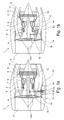
- a jet engine 1 is shown in a longitudinal sectional view.
- the jet engine 1 is formed with a bypass duct 2 and an inlet region 3, with a fan 4 adjoining the inlet region 3 downstream in a manner known per se.
- the fluid flow in the jet engine 1 is divided into a secondary flow and a core flow, wherein the secondary flow through the bypass channel 2 and the core flow flows into an engine core 5, which in turn in a conventional manner with a compressor device 6, a burner 7 and a turbine device 8 is executed.
- the turbine device 8 has three rotor devices 9, 10 and 11, which are designed in a substantially comparable construction and are connected to an engine axis 12.
- an accessory gearbox 13 is disposed in an outer engine casing 14 which defines the bypass duct 2 and constitutes the outer peripheral portion of the jet engine 1.
- the auxiliary gearbox device 13 is in this case connected via a running in the radial direction of the steel engine 1 drive shaft 15 via an inner gear 16 A with the engine axis 12 and is thus driven by the engine axis 12 during operation of the steel engine 1 or supplied with torque.
- From the accessory gearbox 13 various auxiliary equipment 16 and an oil separator 17, which is also referred to as breather, applied to the desired extent with torque.
- an oil tank 18 is provided in the area of the accessory gearbox 13, which constitutes a hydraulic fluid reservoir, from the oil for cooling and lubricating various areas of the jet engine 1, such as storage facilities, Gear pairings of the inner gear 16A and the accessory gearbox 13 and other to be cooled and lubricated assemblies of the jet engine 1, is taken.
- auxiliary gear unit 13 with the ancillaries 16 and the oil separator 17 in the embodiment of the jet engine 1 according to Fig. 1b arranged in the radial direction between the bypass duct 2 and the engine core 5 in a both the bypass duct 2 and the engine core 5 limiting member 19.
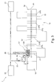
- Fig. 2 to Fig. 4 show three different embodiments of the jet engine 1 according to Fig. 1a in a highly schematized form in the area of the accessory gearbox 13, the ancillaries 16 and the oil separator 17, which in the present case in operative connection with the oil tank 18 and two other areas 20, 21, which are designed here as storage chambers of the jet engine 1 and during operation of the jet engine. 1 be charged with oil from the oil tank 18 for lubrication and cooling.
- the area 20, the storage chamber of the front bearing and the area 21, the storage chamber of the rear bearing of the jet engine 1 represents the Fig. 2 to Fig. 4 described in more detail, the jet engine 1 according to Fig. 1b to a substantially identical extent.
- the present case in an oil separator 17 upstream prechamber 23 opens. Furthermore, the oil tank 18 in the present case is connected to the prechamber 23 in order to be able to introduce an air / oil volume flow from the oil tank 18 and the air / oil volume flows of the bearing chambers 20 and 21 tangentially into the prechamber via the line region 22.
- an interior space 24 of a housing 25 of the auxiliary gearbox 13 is coupled to the pre-chamber 23, wherein at a corresponding printing of the interior 24 also an air-oil flow rate is introduced tangentially into the prechamber 23 from the housing 25 of the accessory gearbox 13.
- the pre-chamber 23 is connected to the oil separator 17, in the interior of which a porous region 26 is rotatably arranged, which can be flowed through by the air-oil volume flow flowing out of the pre-chamber 23.
- the pre-chamber 23 is designed as a pipe or pipe piece designed with an extended inner diameter, which pipe is in any case the pipe carrying the air-oil volume flow.
- the porous region 26 can be driven by the accessory drive device 13 via a gear 27 and acts as a centrifuge in order to be able to reduce the proportion of oil in the air-oil volume flow flowing through the porous region 26 as far as possible.
- the oil content of the air-oil volume flow in the oil separator 17 in the region of the porous region 26 on the one hand as in flowing through a baffle filter and on the other hand reduced as in the region of a centrifuge by the rotation of the porous region 26 by separating the oil from the air.
- the filtered out in the region of the porous region 26 from the air-oil flow rate oil is sucked in the outer region of the oil separator 17 in a manner not shown via a pump device and fed back into the oil tank 18.
- the air flow flowing out of the oil separator 17 in the direction of the environment 28 has only a small load of oil.
- the gear 27 is rotatably connected in addition to other gears 27A to 27E with a transmission shaft 32 and disposed in the interior 24 of the auxiliary gearbox 13.
- a device 29 is provided by means of the oil in the of the pre-chamber 23 in the direction of ⁇ labscheiders 17 flowing air-oil volume flow with a defined droplet size is sprayed.
- the device 29 is configured in such a way that, when oil is injected into the air / oil volume flow flowing in the direction of the oil separator 17, oil drops are formed that are largely larger than drops of oil which can not be filtered out due to their small size in the porous region 26.
- a deflection region for the air-oil volume flows conducted via the line region 22, from the interior 24 and out of the oil tank 18 into the prechamber 23 is provided in the region of the prechamber 23, in the region thereof at least a portion of the oil the air-oil flow rates of the storage chambers 20 and 21, the interior 24 and the oil tank 18 is deposited due to the force acting in the deflection centrifugal force.
- the loading of the air-oil volume flow is reduced by filtering larger droplets already in the deflection of the pre-chamber 23, which have a greater inertia than oil particles with smaller diameters.
- the antechamber 23 is completely integrated in the housing 25 of the accessory gearbox 13, while the oil separator 17 at least partially engages in the interior 24 of the accessory gearbox 13.
- the pre-chamber 23 in the execution of the jet engine 1 according to Fig. 3 completely outside the housing of the auxiliary gearbox 13, while the oil separator 17 to the same extent as in the embodiment of the jet engine 1 according to Fig. 2 partially arranged in the housing 25.
- the air-oil volume flows from the storage chambers 20 and 21, the oil tank 18 and the interior 24 of the auxiliary gearbox 13 initially introduced tangentially into the prechamber 23 and continued over the deflection in the direction of the device 29, in turn, oil in the collected air Oil volume flow is sprayed. Subsequently, the oil-enriched air-oil volume flow is introduced into the oil separator 17 and flows through the porous region 26th
- the embodiment of the jet engine 1 according to Fig. 4 In contrast, this is done without the antechamber 23 and can be used, inter alia, for a jet engine, the oil tank is not integrated into the accessory gearbox 13 and is preferably arranged in a spaced apart from the accessory gearbox 13 space within the jet engine.
- the air-oil volume flows enriched with oil in the area of the storage chambers 20 and 21 as well as in the region of the oil tank 18 are introduced into the deflection region downstream of a line region node 30, in the region of which the line region 22 and another line region 31 connected to the oil tank 18 open , in the area of which a part of the oil is separated from the combined air-oil volume flow.
- a line region node 30 in the region of which the line region 22 and another line region 31 connected to the oil tank 18 open
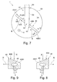
- Fig. 6 shows a cross-sectional view of an embodiment of the device 29 for spraying oil in the guided in a flow region 34 bounded by a wall region 33 air-oil flow rate of the storage chambers 20 and 21, the oil tank 18 and preferably also an air-oil flow rate from the interior 24 of the accessory gearbox 13.
- the device 29 is formed with a movable relative to the wall portion 33 running outlet, via the oil in the air-oil flow rate can be sprayed.
- the outlet region 35 can be acted upon with oil via a bore 36 of a feed region 37 that extends through the wall region 33 essentially in the radial direction.
- the feed region 37 has an element 38 protruding from the wall region 33 in the radial direction into the flow cross-section 34 of the air-oil volume flow, in which an oil feed channel 39 communicating with the bore 36 extends.
- the feed region 37 comprises at least one further element 40 which is rotatably connected to the projecting element 38 and in which a further oil feed channel 41 connected to the oil feed channel 39 is provided.
- a pivot bearing 42 is provided between the projecting element 38 and the further element 40 , which is presently designed as a sliding bearing.
- the pivot bearing 42 comprises a between the projecting element 38 and the further element 40 arranged sliding bushing 43 which receives both radial and axial bearing forces and a rotational movement of the further element 40 relative to the fixedly connected to the wall 33 projecting element 38 at low sliding friction forces allows.
- the further element 40 extends in the flow cross-section 34 of the air-oil volume flow in the radial direction and is in the region of its in relation to the flow direction X of the air-oil volume flow away side with a plurality of holes 44 of the outlet portion 35 executed in the flow cross-section 34 open the air-oil flow rate.
- Fig. 7 shows the device 29 from a in Fig. 6 More detailed view VII. From the illustration according to Fig. 7 shows that the further element 40 is rotatably connected substantially in the middle of the flow cross section 34 of the air-oil flow with the projecting element 38 and starting from the rotational connection with the cantilevered element 38 each one radially in the direction of the flow cross section limiting Wall portion 33 extending
- Diagramarm Suite 40A, 40B includes.
- the partial arm portions 40A and 40B are as in FIG FIGS. 8 and 9 shown, each with a slope 40A1 and 40B1 executed, which are formed opposite to each other.
- the internal energy of the air-oil volume flow becomes a rotational movement of the further element 40 triggering mechanical drive energy converted, wherein the rotation direction resulting from the slopes 40A1 and 40B1 and the flow velocity of the air-oil flow rate in the drawing by the reference symbol R is specified.
- the bores 44 of the further element 40 are arranged obliquely in the further cross-section 34 with respect to the flow direction X of the air-oil volume flow in the flow cross-section 34 at an acute angle ⁇ .
- a flow direction can be impressed on the oil which can be sprayed from the outlet region 35 into the air-oil volume flow in the outlet region 35, which forms an acute angle with the main flow direction X of the air-oil volume flow in the region of the device 29 in order to achieve a desired high degree of distribution
- To achieve oil in the air-oil flow and in addition to the other element 40 by the escape of the oil also impose an angular momentum.
- the axial forces acting on the further element 40 which result from the flow of the air-oil volume flow and from the outflow of the oil from the outlet region 35 or from the bores 44, are preferably coordinated so that in the region of the pivot bearing 42 acting bearing forces are minimal.
- the bores 44 of the further element 40 are present over the substantially further in the flow direction X of the air-oil flow rate further oil passage 41 and in the radial direction of the flow cross-section 34 also in the further element 40 extending additional oil passage 45 with the oil guide channel 39 and also connected to each other via the additional oil passage 45.
- the device 29 of the jet engine 1 with only one or more in the flow direction X of the air-oil flow rate spaced areas according to FIG. 6 to FIG. 9 executed for spraying oil in one or more air-oil flow rates in the jet engine 1 in order to achieve a desired high separation efficiency in the region of the oil separator 17.
Landscapes
- Engineering & Computer Science (AREA)
- Chemical & Material Sciences (AREA)
- Mechanical Engineering (AREA)
- General Engineering & Computer Science (AREA)
- Combustion & Propulsion (AREA)
- Chemical Kinetics & Catalysis (AREA)
- Lubrication Of Internal Combustion Engines (AREA)
- Lubrication Details And Ventilation Of Internal Combustion Engines (AREA)
Abstract
Es wird ein Strahltriebwerk (1) mit einer Einrichtung (29) zum Einsprühen von Öl in einen in einem von einem Wandungsbereich (33) begrenzten Strömungsquerschnitt (34) geführten Luft-Öl-Volumenstrom beschrieben. Der Luft-Öl-Volumenstrom ist zum Abscheiden von Öl durch einen Ölabscheider führbar. Erfindungsgemäß ist das Öl im Bereich der Einrichtung (29) über einen bewegbar gegenüber dem Wandungsbereich (33) ausgeführten Auslassbereich (35) in den Luft-Öl-Volumenstrom einsprühbar.A jet engine (1) with a device (29) for spraying oil into an air-oil volume flow guided in a flow cross-section (34) delimited by a wall region (33) is described. The air-oil volume flow can be passed through an oil separator for separating oil. According to the invention, the oil in the region of the device (29) can be sprayed into the air / oil volume flow via an outlet region (35) which is movable relative to the wall region (33).
Description
Die Erfindung betrifft ein Strahltriebwerk mit einer Einrichtung zum Einsprühen von Öl in einen in einem von einem Wandungsbereich begrenzten Strömungsquerschnitt geführten Luft-Öl-Volumenstrom gemäß der im Oberbegriff des Patentanspruches 1 näher definierten Art.The invention relates to a jet engine with a device for spraying oil in a guided in a limited flow area of a wall region cross-section air-oil flow according to the closer defined in the preamble of
Aus der unveröffentlichten
Der vorliegenden Erfindung liegt die Aufgabe zugrunde, ein Strahltriebwerk mit einer konstruktiv einfachen und mit geringem Aufwand in bestehende Triebwerkssysteme implementierbaren Einrichtung zum Einsprühen von Öl zur Verfügung zu stellen.The present invention has for its object to provide a jet engine with a structurally simple and with little effort implementable in existing engine systems means for spraying oil available.
Erfindungsgemäß wird diese Aufgabe mit einem Strahltriebwerk mit den Merkmalen des Patentanspruches 1 gelöst.According to the invention this object is achieved with a jet engine with the features of
Das erfindungsgemäße Strahltriebwerk ist mit einer Einrichtung zum Einsprühen von Öl in einen in einem von einem Wandungsbereich begrenzten Strömungsquerschnitt geführten Luft-Öl-Volumenstrom ausgebildet, der zum Abscheiden von Öl durch einen Ölabscheider führbar ist.The jet engine according to the invention is formed with a device for injecting oil into an air-oil volume flow which is guided in an area restricted by a wall region flow cross-section, which is feasible for the separation of oil through an oil separator.
Das Öl ist auf konstruktiv einfache Art und Weise im Bereich der Einrichtung über einen bewegbar gegenüber dem Wandungsbereich ausgeführten Auslassbereich in den Luft-Öl-Volumenstrom einsprühbar, womit auch bestehende Strahltriebwerkssysteme mit geringem Aufwand mit einer Einrichtung zum Einsprühen von Öl ausführbar sind.The oil can be sprayed into the air-oil volume flow in a structurally simple manner in the region of the device via an outlet region which is movable relative to the wall region, whereby even existing jet engine systems can be executed with a device for spraying oil with little effort.
Bei einer konstruktiv besonders einfachen Ausführungsform des erfindungsgemäßen Strahltriebwerkes ist der Auslassbereich über eine den Wandungsbereich im Wesentlichen in radialer Richtung durchgreifende Bohrung eines Zuführbereiches mit Öl beaufschlagbar.In a structurally particularly simple embodiment of the jet engine according to the invention, the outlet region can be acted upon with oil via a bore of a feed region which extends through the wall region essentially in the radial direction.
Weist der Zuführbereich wenigstens ein ausgehend vom Wandungsbereich in radialer Richtung in den Strömungsquerschnitt des Luft-Öl-Volumenstromes vorkragendes Element auf, in dem ein mit der Bohrung in Verbindung stehender Ölführkanal verläuft, ist das Öl in einem zur Wandung beabstandeten Bereich des Strömungsquerschnittes in den Luft-Öl-Volumenstrom mit einem gewünschten Verteilungsgrad einsprühbar.If the feed region has at least one element projecting from the wall region in the radial direction into the flow cross section of the air-oil volume flow, in which an oil feed channel communicating with the bore runs, the oil is in a region of the flow cross section which is at a distance from the wall into the air Oil volume flow can be sprayed with a desired degree of distribution.
Umfasst der Zuführbereich wenigstens ein mit dem vorkragenden Element drehbar verbundenes weiteres Element, in dem ein mit dem Ölführkanal verbundener weiterer Ölführkanal vorgesehen ist, ist ein Verteilungsgrad des Öls im Luft-Öl-Volumenstrom über die Drehbewegung des weiteren Elementes mit geringem konstruktivem Aufwand weiter verbesserbar.If the feed region comprises at least one further element which is rotatably connected to the projecting element and in which a further oil feed channel connected to the oil feed channel is provided, a degree of distribution of the oil in the air / oil volume flow can be further improved by means of the rotational movement of the further element with little constructive effort.
Die Drehbewegung des weiteren Elementes gegenüber dem vorkragenden Element ist mit geringem Kraftaufwand auslösbar, wenn zwischen dem vorkragenden Element und dem weiteren Element ein Drehlager, vorzugsweise ein Gleitlager, vorgesehen ist.The rotational movement of the further element relative to the cantilever element can be triggered with little effort if a pivot bearing, preferably a plain bearing, is provided between the cantilevered element and the further element.
Erstreckt sich das weitere Element im Strömungsquerschnitt des Luft-Öl-Volumenstromes in radialer Richtung und ist es im Bereich seiner in Bezug auf die Strömungsrichtung des Luft-Öl-Volumenstromes abgewandten Seite mit wenigstens einer Bohrung des Auslassbereiches ausgeführt, die in den Strömungsquerschnitt des Luft-Öl-Volumenstromes mündet, ist das Öl wenigstens annähernd in Strömungsrichtung des Luft-Öl-Volumenstromes in diesen einsprühbar, womit ein Einsprühwinkel des Öls in den Luft-Öl-Volumenstrom direkt im Mündungsbereich des Zuführbereiches im Wesentlichen unbeeinflusst von der Strömung des Luft-Öl-Volumenstromes einstellbar ist.The further element extends in the radial direction in the flow cross-section of the air-oil volume flow and is designed with at least one bore of the outlet region in the area of its side facing away from the flow direction of the air-oil volume flow, which flows into the flow cross-section of the air flow. Oil volume flow opens, the oil is at least approximately in the flow direction of the air-oil flow rate in this einsprühbar, whereby an injection angle of the oil in the air-oil flow rate directly in the mouth region of the feed area substantially unaffected by the flow of the air-oil Volumetric flow is adjustable.
Wenn eine in Bezug auf die Strömungsrichtung des Luft-Öl-Volumenstromes dem Luft-Öl-Volumenstrom zugewandte Oberfläche des weiteren Elementes zumindest bereichsweise mit einer Schräge ausgebildet ist, über die die innere Energie des Luft-Öl-Volumenstromes in eine eine Drehbewegung des weiteren Elementes auslösende mechanische Antriebsenergie umwandelbar ist, ist der Drehantrieb des weiteren Elementes ohne zusätzliche motorische Einrichtungen realisiert.If a with respect to the flow direction of the air-oil volume flow of the air-oil flow rate facing surface of the further element is at least partially formed with a slope through which the internal energy of the air-oil flow in a rotational movement of another element triggering mechanical drive energy is convertible, the rotary drive of the other element is realized without additional motor devices.
Das Öl ist bei einer weiteren vorteilhaften Ausführungsform des erfindungsgemäßen Strahltriebwerkes mit gutem Verteilungsgrad in den Luft-Öl-Volumenstrom einleitbar, wenn das weitere Element im Wesentlichen in der Mitte des Strömungsquerschnittes des Luft-Öl-Volumenstromes drehbar mit dem vorkragenden Element verbunden ist und ausgehend von der Drehverbindung mit dem vorkragenden Element jeweils einen sich radial in Richtung der den Strömungsquerschnitt begrenzenden Wandung erstreckenden Teilarmbereich umfasst.The oil can be introduced in a further advantageous embodiment of the jet engine according to the invention with a good degree of distribution in the air-oil flow, when the other element is substantially connected in the middle of the flow cross-section of the air-oil flow rate rotatably connected to the cantilevered element and starting from the rotary connection with the projecting element in each case comprises a partial arm region extending radially in the direction of the wall defining the flow cross section.
Sind die Teilarmbereiche jeweils mit einer Schräge ausgeführt, die gegengleich zueinander ausgebildet sind, wird das weitere Element durch eine Anströmung des Luft-Öl-Volumenstromes in gewünschtem Umfang ohne eine motorische Einrichtung in Drehung versetzt.If the Teilarmbereiche are each designed with a slope that are formed opposite to each other, the other element is set by a flow of air-oil flow in the desired amount without a motor device in rotation.
Ein Verteilungsgrad des in den Luft-Öl-Volumenstrom einzuleitenden Öles ist mit geringem Aufwand an den jeweils vorliegenden Anwendungsfall optimal einstellbar, wenn dem aus dem Auslassbereich in den Luft-Öl-Volumenstrom einsprühbarem Öl im Auslassbereich eine Strömungsrichtung aufprägbar ist, die mit der Hauptströmungsrichtung des Luft-Öl-Volumenstromes im Bereich der Einrichtung einen spitzen Winkel, d. h. einen Winkel von 0° bis 90°, einschließt.A degree of distribution of the oil to be introduced into the air-oil volume flow can be set optimally with little effort to the respective application case if a flow direction can be imposed on the oil which can be sprayed from the outlet region into the air-oil volume flow in the outlet region, which flow direction is the main flow direction Air-oil flow in the area of the device an acute angle, d. H. an angle of 0 ° to 90 °.
Zur Einstellung eines gewünschten Verteilungsgrades des Öls im Luft-Öl-Volumenstrom kann im Mündungsbereich der Bohrung des Auslassbereiches eine Düseneinrichtung vorgesehen sein, in deren Bereich das zuzuführende Öl vorzugsweise vernebelbar ist.To set a desired degree of distribution of the oil in the air-oil volume flow, a nozzle device may be provided in the mouth region of the bore of the outlet region, in the region of which the oil to be supplied is preferably wettable.
Umfasst der Auslassbereich mehrere in radialer Richtung des Strömungsquerschnittes des Luft-Öl-Volumenstromes zueinander beabstandete Bohrungen, die jeweils in den Strömungsquerschnitt münden, ist das Öl bevorzugterweise über den gesamten radialen Bereich des Strömungsquerschnittes in den Luft-Öl-Volumenstrom im Bereich mehrerer Mündungsbereiche einsprühbar und mit hohem Verteilungsgrad in den Luft-Öl-Volumenstrom einbringbar.If the outlet region comprises a plurality of bores which are spaced apart from each other in the radial direction of the flow cross section of the air-oil volume flow and which each open into the flow cross-section, the oil can preferably be sprayed over the entire radial region of the flow cross-section into the air-oil volume flow in the region of a plurality of mouth regions and Can be introduced into the air / oil volume flow with a high degree of distribution.
Bei einer konstruktiv einfachen und bauraumgünstigen Ausführungsform des Strahltriebwerkes sind die Bohrungen des weiteren Elementes über den Ölführkanal miteinander verbunden.In a structurally simple and space-saving embodiment of the jet engine, the holes of the further element are connected to one another via the oil guide channel.
Die Abscheideleistung im Bereich eines Ölabscheiders ist bei einer Weiterbildung des erfindungsgemäßen Strahltriebwerkes dadurch verbesserbar, dass die Einrichtung des Strahltriebwerks in Strömungsrichtung des Luft-Öl-Volumenstromes mehrere zueinander beabstandete Bereiche zum Einsprühen von Öl aufweist, da Tropfendurchmesser von im Luft-Öl-Volumenstrom mitgeführtem Öl im Bereich mehrerer in Strömungsrichtung des Luft-Öl-Volumenstromes nacheinander folgenden Eingabestellen des Öls in gewünschtem Umfang einstellbar bzw. vergrößerbar sind.The separation efficiency in the region of an oil separator can be improved in a development of the jet engine according to the invention in that the device of the jet engine in the flow direction of the air-oil flow rate Having multiple spaced-apart areas for spraying oil, since droplet diameter of entrained in the air-oil flow rate oil in the range of several successively following in the flow direction of the air-oil flow rate input points of the oil to the desired extent or be increased.
Sowohl die in den Patentansprüchen angegebenen Merkmale als auch die in den nachfolgenden Ausführungsbeispielen des erfindungsgemäßen Strahltriebwerkes angegebenen Merkmale sind jeweils für sich alleine oder in beliebiger Kombination miteinander geeignet, den erfindungsgemäßen Gegenstand weiterzubilden. Die jeweiligen Merkmalskombinationen stellen hinsichtlich der Weiterbildung des Gegenstandes nach der Erfindung keine Einschränkung dar, sondern weisen im Wesentlichen lediglich beispielhaften Charakter auf.Both the features specified in the claims and the features specified in the following embodiments of the jet engine according to the invention are each suitable alone or in any combination with each other to further develop the subject invention. The respective feature combinations represent no limitation with respect to the development of the subject matter according to the invention, but essentially have only an exemplary character.
Weitere Vorteile und vorteilhafte Ausführungsformen des erfindungsgemäßen Strahltriebwerkes ergeben sich aus den Patentansprüchen und den nachfolgend unter Bezugnahme auf die Zeichnung prinzipmäßig beschriebenen Ausführungsbeispielen, wobei in der Beschreibung der verschiedenen Ausführungsbeispiele zugunsten der Übersichtlichkeit für bau- und funktionsgleiche Bauteile dieselben Bezugszeichen verwendet werden.Further advantages and advantageous embodiments of the jet engine according to the invention will become apparent from the claims and the embodiments described in principle below with reference to the drawings, the same reference numerals are used in the description of the various embodiments in favor of clarity for construction and functionally identical components.
Es zeigt:
- Fig. 1a
- eine stark schematisierte Längsschnittansicht eines Strahltriebwerkes mit einer im Bläsergehäuse angeordneten Nebenaggregategetriebeeinrichtung;
- Fig. 1b
- eine
Fig. 1a entsprechende Darstellung eines Strahltriebwerkes mit im Bereich des Triebwerkskerns montierter Nebenaggregategetriebeeinrichtung; - Fig. 2
- eine stark schematisierte Teildarstellung des Strahltriebwerkes gemäß
Fig. 1a bzw.Fig. 1b mit im Bereich der Nebenaggregategetriebeeinrichtung angeordnetem Ölabscheider und zugeordneter Vorkammer, die in einem Gehäuse der Nebenaggregategetriebeeinrichtung vorgesehen ist; - Fig. 3
- eine
Fig. 2 entsprechende Darstellung einer vonFig. 2 abweichenden Ausführungsform des Strahltriebwerkes gemäßFig. 1a bzw.Fig. 1b mit außerhalb eines Gehäuses der Nebenaggregategetriebeeinrichtung angeordneter Vorkammer; - Fig. 4
- eine stark schematisierte Teildarstellung des Strahltriebwerkes gemäß
Fig. 1a bzw.Fig. 1b mit stromauf des Ölabscheiders angeordneter Einrichtung zum Einsprühen von Öl in einen Luft-Öl-Volumenstrom; - Fig. 5
- eine vergrößerte Darstellung eines in
Fig. 4 näher gekennzeichneten Bereiches V; - Fig. 6
- eine detailliertere Querschnittansicht einer Ausführungsform der Einrichtung zum Einsprühen von Öl in einen Luft-Öl-Volumenstrom;
- Fig. 7
- die Einrichtung zum Einsprühen von Öl gemäß
Fig. 6 aus einer inFig. 6 näher gekennzeichneten Ansicht VII; - Fig. 8
- eine Schnittansicht der Einrichtung zum Einsprühen von Öl gemäß
Fig. 6 entlang einer inFig. 7 näher gekennzeichneten Schnittebene VIII-VIII; und - Fig. 9
- eine
Fig. 8 entsprechende Darstellung der Einrichtung zum Einsprühen von Öl gemäßFig. 6 entlang einer inFig. 7 näher gekennzeichneten Schnittebene IX-IX.
- Fig. 1a
- a highly schematic longitudinal sectional view of a jet engine with an arranged in the fan housing accessory gearbox;
- Fig. 1b
- a
Fig. 1a corresponding representation of a jet engine with mounted in the region of the engine core accessory gearbox; - Fig. 2
- a highly schematic partial representation of the jet engine according to
Fig. 1a respectively.Fig. 1b with disposed in the region of the accessory gearbox oil separator and associated pre-chamber, which is provided in a housing of the accessory gearbox; - Fig. 3
- a
Fig. 2 corresponding representation of aFig. 2 deviating embodiment of the jet engine according toFig. 1a respectively.Fig. 1b with an antechamber arranged outside a housing of the auxiliary gearbox; - Fig. 4
- a highly schematic partial representation of the jet engine according to
Fig. 1a respectively.Fig. 1b means disposed upstream of the oil separator for injecting oil into an air-to-oil volume flow; - Fig. 5
- an enlarged view of an in
Fig. 4 further designated area V; - Fig. 6
- a more detailed cross-sectional view of an embodiment of the device for injecting oil into an air-oil flow rate;
- Fig. 7
- the device for spraying oil according to
Fig. 6 from an inFig. 6 closer marked view VII; - Fig. 8
- a sectional view of the device for spraying oil according to
Fig. 6 along an inFig. 7 more precisely marked section plane VIII-VIII; and - Fig. 9
- a
Fig. 8 corresponding representation of the device for spraying oil according toFig. 6 along an inFig. 7 closer marked cutting plane IX-IX.
In
Die Turbineneinrichtung 8 weist vorliegend drei Rotorvorrichtungen 9, 10 und 11 auf, welche in im Wesentlichen vergleichbarer Bauweise ausgebildet sind und mit einer Triebwerksachse 12 verbunden sind.In the present case, the
Bei der Ausführung des Strahltriebwerks 1 gemäß
Im Unterschied hierzu ist die Nebenaggregategetriebeeinrichtung 13 mit den Nebenaggregaten 16 und dem Ölabscheider 17 bei der Ausführung des Strahltriebwerks 1 gemäß
Bei der in
Dabei besteht die Möglichkeit, dass die Vorkammer 23 als ein mit erweitertem Innendurchmesser ausgeführtes Rohr bzw. Rohrstück ausgeführt ist, welches ohnehin die den Luft-Öl-Volumenstrom führende Leitung darstellt.In this case, there is the possibility that the pre-chamber 23 is designed as a pipe or pipe piece designed with an extended inner diameter, which pipe is in any case the pipe carrying the air-oil volume flow.
Der poröse Bereich 26 ist vorliegend über ein Zahnrad 27 von der Nebenaggregategetriebeeinrichtung 13 antreibbar und wirkt als Zentrifuge, um den Anteil an Öl des durch den porösen Bereich 26 strömenden Luft-Öl-Volumenstromes soweit als möglich reduzieren zu können. Dabei wird der Ölanteil des Luft-Öl-Volumenstromes im Ölabscheider 17 im Bereich des porösen Bereiches 26 einerseits wie beim Durchströmen eines Prallfilters und andererseits wie im Bereich einer Zentrifuge durch die Rotation des porösen Bereiches 26 durch Abscheiden des Öls aus der Luft reduziert. Das im Bereich des porösen Bereiches 26 aus dem Luft-Öl-Volumenstrom ausgefilterte Öl wird im äußeren Bereich des Ölabscheiders 17 in nicht näher dargestellter Art und Weise über eine Pumpeneinrichtung abgesaugt und zurück in den Öltank 18 geführt. Der aus dem Ölabscheider 17 in Richtung der Umgebung 28 ausströmende Luftstrom weist nur eine geringe Beladung an Öl auf. Das Zahnrad 27 ist neben weiteren Zahnrädern 27A bis 27E drehfest mit einer Getriebewelle 32 verbunden und im Innenraum 24 der Nebenaggregategetriebeeinrichtung 13 angeordnet.In the present case, the
Um die Beladung des in Richtung der Umgebung 28 abströmenden Luftvolumenstromes mit Öl möglichst gering einstellen zu können, ist vorliegend im Bereich des Übergangs zwischen der Vorkammer 23 und dem Ölabscheider 17 eine Einrichtung 29 vorgesehen, mittels der Öl in den von der Vorkammer 23 in Richtung des Ölabscheiders 17 strömenden Luft-Öl-Volumenstrom mit definierter Tröpfchengröße eingesprüht wird. Hierfür ist die Einrichtung 29 derart konfiguriert, dass beim Einsprühen von Öl in den in Richtung des Ölabscheiders 17 strömenden Luft-ÖlVolumenstrom Öltropfen entstehen, die größtenteils größer sind als Öltropfen, die aufgrund ihrer geringen Größe im porösen Bereich 26 nicht ausfilterbar sind.In order to minimize the loading of the outflowing in the direction of the
Wiederum stromauf der Einrichtung 29 ist im Bereich der Vorkammer 23 ein Umlenkbereich für die über den Leitungsbereich 22, aus dem Innenraum 24 und aus dem Öltank 18 in die Vorkammer 23 geleiteten Luft-Öl-Volumenströme vorgesehen, in dessen Bereich zumindest ein Teil des Öls aus den Luft-Öl-Volumenströmen der Lagerkammern 20 und 21, des Innenraumes 24 und des Öltanks 18 aufgrund der im Umlenkbereich wirkenden Zentrifugalkraft abgeschieden wird. Damit wird bereits im Umlenkbereich der Vorkammer 23 die Beladung des Luft-Öl-Volumenstromes durch Ausfiltern größerer Tröpfchen reduziert, die eine größere Trägheit als Ölpartikel mit kleineren Durchmessern aufweisen.Once again upstream of the
Anschließend werden die noch im Luft-Öl-Volumenstrom, der in Richtung des Ölabscheiders 17 aus der Vorkammer 23 ausströmt, vorhandenen kleineren Tröpfchen durch das Einsprühen von Öl über die Einrichtung 29 vergrößert, was durch die jeweils vorliegenden Anziehungskräfte zwischen den einzelnen Öltröpfchen begünstigt wird. Durchströmt der mit Öl angereicherte Luft-Öl-Volumenstrom den Ölabscheider 17 und dessen porösen Bereich 26, der im Betrieb des Strahltriebwerks 1 entsprechend rotiert, wird ein weiterer wesentlicher Anteil des im Luft-Öl-Volumenstrom vorhandenen Öls abgeschleudert und anschließend aus dem Ölabscheider 17 in Richtung des Öltanks 18 abgesaugt. Die durch die Auswaschung des Öls nunmehr vergrößerten Ölpartikel können durch das Einspritzen von Öl von dem Metallschaum 26 im Breather 17 wesentlich effizienter separiert werden, womit Ölverluste des Strahltriebwerks 1 durch verringerte Emissionen in Richtung der Umgebung 28 minimiert sind.Subsequently, the still present in the air-oil flow rate, which flows out in the direction of the
Alternativ zu der vorstehenden Beschreibung besteht auch die Möglichkeit, dass über die Einrichtung 29 stromauf des als Zentrifuge wirkenden Umlenkbereiches der Vorkammer 23, im Bereich der Lagerkammern und/oder im Bereich von Abluftansaugpunkten Öl in einen oder mehrere Luft-Öl-Volumenströme im Strahltriebwerk 1 eingeleitet wird und die sich im Luft-Öl-Volumenstrom stromab der Einrichtung 29 aufgrund der Vereinigung der Öltröpfchen bildenden größeren Tropfen im Umlenkbereich der Vorkammer 23 aufgrund der wirkenden Zentrifugalkraft abgeschieden werden. Anschließend erfolgt der weitere vorbeschriebene Abscheideprozess im rotierenden porösen Bereich 26 des Ölabscheiders 17, bevor die aus dem Ölabscheider 17 ausströmende Luft mit nur geringer Beladung an Öl in Richtung der Umgebung 28 ausströmt.As an alternative to the above description, there is also the possibility that via the
Darüber hinaus besteht auch die Möglichkeit, dass über die Einrichtung 29 bereits in den Lagerkammern bzw. im Innenraum weiterer Verbraucher von Absperrluft, wie dem inneren Getriebe des Strahltriebwerks 1, Öl in einen oder mehrere Luft-Öl-Volumenströme eingeleitet wird und die sich im Luft-Öl-Volumenstrom stromab der Einrichtung 29 aufgrund der Vereinigung der Öltröpfchen bildenden größeren Tropfen im Umlenkbereich der Vorkammer 23 aufgrund der wirkenden Zentrifugalkraft abgeschieden werden. Anschließend erfolgt der weitere vorbeschriebene Abscheideprozess im rotierenden porösen Bereich 26 des Ölabscheiders 17, bevor die aus dem Ölabscheider 17 strömende Luft mit nur geringer Beladung an Öl in Richtung der Umgebung 28 abgegeben wird.In addition, there is also the possibility that via the
Bei der Ausführung gemäß
Im Unterschied hierzu ist die Vorkammer 23 bei der Ausführung des Strahltriebwerks 1 gemäß
Die Ausführung des Strahltriebwerks 1 gemäß
Zwischen dem vorkragenden Element 38 und dem weiteren Element 40 ist ein Drehlager 42 vorgesehen, das vorliegend als Gleitlager ausgebildet ist. Das Drehlager 42 umfasst eine zwischen dem vorkragenden Element 38 und dem weiteren Element 40 angeordnete Gleitbuchse 43, die sowohl in radialer Richtung als auch in axialer Richtung Lagerkräfte aufnimmt und eine Drehbewegung des weiteren Elementes 40 gegenüber dem fest mit der Wandung 33 verbundenen vorkragenden Element 38 bei geringen Gleitreibungskräften ermöglicht. Das weitere Element 40 erstreckt sich im Strömungsquerschnitt 34 des Luft-Öl-Volumenstromes in radialer Richtung und ist im Bereich seiner in Bezug auf die Strömungsrichtung X des Luft-Öl-Volumenstromes abgewandten Seite mit mehreren Bohrungen 44 des Auslassbereiches 35 ausgeführt, die in den Strömungsquerschnitt 34 des Luft-Öl-Volumenstromes münden.Between the projecting
Die Bohrungen 44 des weiteren Elementes 40 sind vorliegend in Bezug auf die Strömungsrichtung X des Luft-Öl-Volumenstromes im Strömungsquerschnitt 34 unter einem spitzen Winkel α schräg verlaufend im weiteren Element 40 angeordnet. Damit ist dem aus dem Auslassbereich 35 in den Luft-Öl-Volumenstrom einsprühbaren Öl im Auslassbereich 35 eine Strömungsrichtung aufprägbar, die mit der Hauptströmungsrichtung X des Luft-Öl-Volumenstromes im Bereich der Einrichtung 29 einen spitzen Winkel einschließt, um einen gewünscht hohen Verteilungsgrad des Öls im Luft-Öl-Volumenstrom zu erreichen und zusätzlich dem weiteren Element 40 durch den Austritt des Öls ebenfalls einen Drehimpuls aufzuprägen.In the present case, the
Die am weiteren Element 40 angreifenden Axialkräfte, die aus der Anströmung des Luft-Öl-Volumenstromes und aus der Ausströmung des Öls aus dem Auslassbereich 35 bzw. aus den Bohrungen 44 resultieren, sind vorzugsweise derart aufeinander abgestimmt, dass im Bereich des Drehlagers 42 wirkende Lagerkräfte minimal sind.The axial forces acting on the
Die Bohrungen 44 des weiteren Elementes 40 sind vorliegend über den im Wesentlichen in Strömungsrichtung X des Luft-Öl-Volumenstromes verlaufenden weiteren Ölführkanal 41 und einen sich in radialer Richtung des Strömungsquerschnittes 34 ebenfalls im weiteren Element 40 verlaufenden zusätzlichen Ölkanal 45 mit dem Ölführkanal 39 und auch untereinander über den zusätzlichen Ölkanal 45 verbunden.The
In Abhängigkeit des jeweils vorliegenden Anwendungsfalles ist die Einrichtung 29 des Strahltriebwerks 1 mit lediglich einer oder mit mehreren in Strömungsrichtung X des Luft-Öl-Volumenstromes zueinander beabstandeten Bereichen gemäß
- 11
- StrahltriebwerkJet engine
- 22
- NebenstromkanalBypass duct
- 33
- Einlaufbereichintake area
- 44
- Bläserblowers
- 55
- TriebwerkskernEngine core
- 66
- Verdichtereinrichtungcompressor means
- 77
- Brennerburner
- 88th
- TurbineneinrichtungThe turbine apparatus
- 9, 10, 119, 10, 11
- Rotorvorrichtungrotor device
- 1212
- TriebwerksachseThe engine axis
- 1313
- NebenaggregategetriebeeinrichtungAncillaries transmission device
- 1414
- TriebwerksgehäuseEngine casing
- 1515
- Antriebswelledrive shaft
- 1616
- Nebenaggregateancillaries
- 16A16A
- inneres Getriebeinner gear
- 1717
- Ölabscheideroil separator
- 1818
- Öltankoil tank
- 1919
- Bauteilcomponent
- 2020
- Bereich, vordere LagerkammerArea, front storage chamber
- 2121
- Bereich, hintere LagerkammerArea, rear storage chamber
- 2222
- Leitungsbereichmanagement area
- 2323
- Vorkammerantechamber
- 2424
- Innenrauminner space
- 2525
- Gehäusecasing
- 2626
- poröser Bereichporous area
- 2727
- Zahnradgear
- 27A bis 27E27A to 27E
- Zahnradgear
- 2828
- UmgebungSurroundings
- 2929
- EinrichtungFacility
- 3030
- LeitungsbereichsknotenLine region nodes
- 3131
- weiterer Leitungsbereichanother line area
- 3232
- Getriebewellegear shaft
- 3333
- Wandungsbereichwall region
- 3434
- StrömungsquerschnittFlow area
- 3535
- Auslassbereichoutlet
- 3636
- Bohrungdrilling
- 3737
- Zuführbereichfeeding
- 3838
- Elementelement
- 3939
- ÖlführkanalOil duct
- 4040
- weiteres Elementanother element
- 40A, 40B40A, 40B
- TeilarmbereichTeilarmbereich
- 40A1, 40B140A1, 40B1
- Schrägeslope
- 4141
- weiterer Ölführkanalfurther oil duct
- 4242
- Drehlagerpivot bearing
- 4343
- Gleitbuchsebush
- 4444
- Bohrungdrilling
- 4545
- zusätzlicher Ölkanaladditional oil channel
- RR
- Drehrichtungdirection of rotation
- XX
- Hauptströmungsrichtung des Luft-Öl-VolumenstromesMain flow direction of the air-oil volume flow
- αα
- spitzer Winkelacute angle
Claims (14)
Applications Claiming Priority (1)
| Application Number | Priority Date | Filing Date | Title |
|---|---|---|---|
| DE102013112773.8A DE102013112773A1 (en) | 2013-11-19 | 2013-11-19 | Jet engine with a device for injecting oil into an air-oil volume flow |
Publications (2)
| Publication Number | Publication Date |
|---|---|
| EP2873838A1 true EP2873838A1 (en) | 2015-05-20 |
| EP2873838B1 EP2873838B1 (en) | 2017-06-21 |
Family
ID=51790597
Family Applications (1)
| Application Number | Title | Priority Date | Filing Date |
|---|---|---|---|
| EP14190227.0A Not-in-force EP2873838B1 (en) | 2013-11-19 | 2014-10-24 | Jet engine with a device for spraying oil into an air-oil volume flow |
Country Status (3)
| Country | Link |
|---|---|
| US (1) | US9677422B2 (en) |
| EP (1) | EP2873838B1 (en) |
| DE (1) | DE102013112773A1 (en) |
Families Citing this family (6)
| Publication number | Priority date | Publication date | Assignee | Title |
|---|---|---|---|---|
| DE102013106879A1 (en) | 2013-07-01 | 2015-01-08 | Rolls-Royce Deutschland Ltd & Co Kg | Jet engine with at least one oil separator |
| DE102013106877A1 (en) * | 2013-07-01 | 2015-01-08 | Rolls-Royce Deutschland Ltd & Co Kg | Jet engine with at least one oil separator, through which an air-oil volume flow is feasible |
| DE102014113128A1 (en) * | 2014-09-11 | 2016-03-17 | Rolls-Royce Deutschland Ltd & Co Kg | Tank device of an aircraft engine with a device for introducing oil |
| DE102014119066A1 (en) * | 2014-12-18 | 2016-06-23 | Rolls-Royce Deutschland Ltd & Co Kg | Aero engine with a device for separating oil |
| FR3056635B1 (en) * | 2016-09-26 | 2020-05-29 | Safran Helicopter Engines | SYSTEM FOR DEHUILING AN AIR / OIL MIXTURE FOR PRESSURIZING SEALS OF A TURBOMACHINE |
| US11168585B2 (en) * | 2018-01-08 | 2021-11-09 | Raytheon Technologies Corporation | Geared gas turbine engine with improved breather air venting |
Citations (4)
| Publication number | Priority date | Publication date | Assignee | Title |
|---|---|---|---|---|
| US4342489A (en) * | 1980-10-07 | 1982-08-03 | Teledyne Industries, Inc. | Bearing lubricating injector |
| US20030039421A1 (en) * | 2001-08-22 | 2003-02-27 | Fisher Kenneth Lee | Bi-directional oil scoop for bearing lubrication |
| US20090134243A1 (en) * | 2007-11-28 | 2009-05-28 | General Electric Company | Air-oil separator |
| WO2013168232A1 (en) * | 2012-05-08 | 2013-11-14 | トヨタ自動車株式会社 | Internal combustion engine |
Family Cites Families (6)
| Publication number | Priority date | Publication date | Assignee | Title |
|---|---|---|---|---|
| US7935164B2 (en) * | 2007-11-28 | 2011-05-03 | General Electric Company | Vortex air-oil separator system |
| FR2929325B1 (en) * | 2008-03-26 | 2012-09-28 | Snecma | DEVICE AND METHOD FOR PRESSURE BALANCING IN A TURBOELECTOR BEARING ENCLOSURE |
| CN104081020A (en) * | 2011-12-01 | 2014-10-01 | 丰田自动车株式会社 | Internal combustion engine with supercharger |
| DE102013106879A1 (en) | 2013-07-01 | 2015-01-08 | Rolls-Royce Deutschland Ltd & Co Kg | Jet engine with at least one oil separator |
| DE102013112771A1 (en) * | 2013-11-19 | 2015-05-21 | Rolls-Royce Deutschland Ltd & Co Kg | Jet engine with a device for spraying oil |
| DE102014106583A1 (en) * | 2014-05-09 | 2015-11-12 | Rolls-Royce Deutschland Ltd & Co Kg | Device of an aircraft engine for separating oil from an air-oil volume flow |
-
2013
- 2013-11-19 DE DE102013112773.8A patent/DE102013112773A1/en not_active Withdrawn
-
2014
- 2014-10-24 EP EP14190227.0A patent/EP2873838B1/en not_active Not-in-force
- 2014-11-04 US US14/532,772 patent/US9677422B2/en not_active Expired - Fee Related
Patent Citations (4)
| Publication number | Priority date | Publication date | Assignee | Title |
|---|---|---|---|---|
| US4342489A (en) * | 1980-10-07 | 1982-08-03 | Teledyne Industries, Inc. | Bearing lubricating injector |
| US20030039421A1 (en) * | 2001-08-22 | 2003-02-27 | Fisher Kenneth Lee | Bi-directional oil scoop for bearing lubrication |
| US20090134243A1 (en) * | 2007-11-28 | 2009-05-28 | General Electric Company | Air-oil separator |
| WO2013168232A1 (en) * | 2012-05-08 | 2013-11-14 | トヨタ自動車株式会社 | Internal combustion engine |
Also Published As
| Publication number | Publication date |
|---|---|
| EP2873838B1 (en) | 2017-06-21 |
| DE102013112773A1 (en) | 2015-05-21 |
| US9677422B2 (en) | 2017-06-13 |
| US20150135660A1 (en) | 2015-05-21 |
Similar Documents
| Publication | Publication Date | Title |
|---|---|---|
| EP2873837B1 (en) | Jet engine with a device for injecting oil | |
| EP2873838B1 (en) | Jet engine with a device for spraying oil into an air-oil volume flow | |
| EP2886931B1 (en) | Device of a jet engine with at least one component in a housing which can be rotated relative to the housing | |
| EP2942491B1 (en) | Device of an aircraft engine for separating oil from an oil air flow | |
| EP2821599B1 (en) | Jet engine with at least one oil separator | |
| EP3456945B1 (en) | Transmission with an oil distribution system | |
| DE60308574T2 (en) | Air / oil separator | |
| DE60130234T2 (en) | AIR / OIL SEPARATOR | |
| EP2821598B1 (en) | Jet engine with at least one oil separator, through which an air-oil volume flow can be conveyed | |
| DE102006024816A1 (en) | Device for venting a crankcase | |
| EP3382180B1 (en) | Jet engine with a chamber | |
| EP2995781A1 (en) | Tank device of an aircraft engine with a device for feeding in oil | |
| EP3194812B1 (en) | Guiding means for arrangement in the area of a transmission and/or a clutch of a motor vehicle | |
| DE102005042725A1 (en) | Axial cyclone used as oil mist separator in combustion engine of motor vehicle, has gyrator that rotates around axle inside tubular housing, in which tubular housing function as oil mist separator | |
| EP3029277A1 (en) | Aircraft engine with a breather device for removing oil and a device for increasing a pressure | |
| DE102014119066A1 (en) | Aero engine with a device for separating oil | |
| DE102014113132A1 (en) | Aircraft with a storage chamber and a device for introducing oil | |
| EP3492709A1 (en) | Aircraft engine | |
| DE69026045T2 (en) | Liquid degassing pump | |
| EP2832448B1 (en) | Oil centrifuge with centrifuge rotor | |
| DE102013108668A1 (en) | Jet engine, accessory gearbox and apparatus for separating oil from an air-to-oil volume flow | |
| DE102016114394A1 (en) | Device of a turbomachine for separating oil from an air-oil volume flow | |
| DE1957005A1 (en) | Oil suction pump and drive device for additional units | |
| DE102009035895A1 (en) | Filer assembly for cleaning of crankcase gases, comprises rotatably mounted filter element for deposition of residues | |
| DE102016008554A1 (en) | Shaft with axial fluid passage |
Legal Events
| Date | Code | Title | Description |
|---|---|---|---|
| PUAI | Public reference made under article 153(3) epc to a published international application that has entered the european phase |
Free format text: ORIGINAL CODE: 0009012 |
|
| 17P | Request for examination filed |
Effective date: 20141024 |
|
| AK | Designated contracting states |
Kind code of ref document: A1 Designated state(s): AL AT BE BG CH CY CZ DE DK EE ES FI FR GB GR HR HU IE IS IT LI LT LU LV MC MK MT NL NO PL PT RO RS SE SI SK SM TR |
|
| AX | Request for extension of the european patent |
Extension state: BA ME |
|
| R17P | Request for examination filed (corrected) |
Effective date: 20151109 |
|
| RBV | Designated contracting states (corrected) |
Designated state(s): AL AT BE BG CH CY CZ DE DK EE ES FI FR GB GR HR HU IE IS IT LI LT LU LV MC MK MT NL NO PL PT RO RS SE SI SK SM TR |
|
| 17Q | First examination report despatched |
Effective date: 20160331 |
|
| GRAP | Despatch of communication of intention to grant a patent |
Free format text: ORIGINAL CODE: EPIDOSNIGR1 |
|
| INTG | Intention to grant announced |
Effective date: 20170303 |
|
| GRAS | Grant fee paid |
Free format text: ORIGINAL CODE: EPIDOSNIGR3 |
|
| GRAA | (expected) grant |
Free format text: ORIGINAL CODE: 0009210 |
|
| AK | Designated contracting states |
Kind code of ref document: B1 Designated state(s): AL AT BE BG CH CY CZ DE DK EE ES FI FR GB GR HR HU IE IS IT LI LT LU LV MC MK MT NL NO PL PT RO RS SE SI SK SM TR |
|
| REG | Reference to a national code |
Ref country code: GB Ref legal event code: FG4D Free format text: NOT ENGLISH |
|
| REG | Reference to a national code |
Ref country code: CH Ref legal event code: EP |
|
| REG | Reference to a national code |
Ref country code: IE Ref legal event code: FG4D Free format text: LANGUAGE OF EP DOCUMENT: GERMAN |
|
| REG | Reference to a national code |
Ref country code: AT Ref legal event code: REF Ref document number: 903159 Country of ref document: AT Kind code of ref document: T Effective date: 20170715 |
|
| REG | Reference to a national code |
Ref country code: DE Ref legal event code: R096 Ref document number: 502014004306 Country of ref document: DE |
|
| REG | Reference to a national code |
Ref country code: NL Ref legal event code: MP Effective date: 20170621 Ref country code: FR Ref legal event code: PLFP Year of fee payment: 4 |
|
| PG25 | Lapsed in a contracting state [announced via postgrant information from national office to epo] |
Ref country code: LT Free format text: LAPSE BECAUSE OF FAILURE TO SUBMIT A TRANSLATION OF THE DESCRIPTION OR TO PAY THE FEE WITHIN THE PRESCRIBED TIME-LIMIT Effective date: 20170621 Ref country code: HR Free format text: LAPSE BECAUSE OF FAILURE TO SUBMIT A TRANSLATION OF THE DESCRIPTION OR TO PAY THE FEE WITHIN THE PRESCRIBED TIME-LIMIT Effective date: 20170621 Ref country code: NO Free format text: LAPSE BECAUSE OF FAILURE TO SUBMIT A TRANSLATION OF THE DESCRIPTION OR TO PAY THE FEE WITHIN THE PRESCRIBED TIME-LIMIT Effective date: 20170921 Ref country code: GR Free format text: LAPSE BECAUSE OF FAILURE TO SUBMIT A TRANSLATION OF THE DESCRIPTION OR TO PAY THE FEE WITHIN THE PRESCRIBED TIME-LIMIT Effective date: 20170922 Ref country code: FI Free format text: LAPSE BECAUSE OF FAILURE TO SUBMIT A TRANSLATION OF THE DESCRIPTION OR TO PAY THE FEE WITHIN THE PRESCRIBED TIME-LIMIT Effective date: 20170621 |
|
| REG | Reference to a national code |
Ref country code: LT Ref legal event code: MG4D |
|
| PG25 | Lapsed in a contracting state [announced via postgrant information from national office to epo] |
Ref country code: RS Free format text: LAPSE BECAUSE OF FAILURE TO SUBMIT A TRANSLATION OF THE DESCRIPTION OR TO PAY THE FEE WITHIN THE PRESCRIBED TIME-LIMIT Effective date: 20170621 Ref country code: BG Free format text: LAPSE BECAUSE OF FAILURE TO SUBMIT A TRANSLATION OF THE DESCRIPTION OR TO PAY THE FEE WITHIN THE PRESCRIBED TIME-LIMIT Effective date: 20170921 Ref country code: LV Free format text: LAPSE BECAUSE OF FAILURE TO SUBMIT A TRANSLATION OF THE DESCRIPTION OR TO PAY THE FEE WITHIN THE PRESCRIBED TIME-LIMIT Effective date: 20170621 Ref country code: NL Free format text: LAPSE BECAUSE OF FAILURE TO SUBMIT A TRANSLATION OF THE DESCRIPTION OR TO PAY THE FEE WITHIN THE PRESCRIBED TIME-LIMIT Effective date: 20170621 Ref country code: SE Free format text: LAPSE BECAUSE OF FAILURE TO SUBMIT A TRANSLATION OF THE DESCRIPTION OR TO PAY THE FEE WITHIN THE PRESCRIBED TIME-LIMIT Effective date: 20170621 |
|
| PG25 | Lapsed in a contracting state [announced via postgrant information from national office to epo] |
Ref country code: CZ Free format text: LAPSE BECAUSE OF FAILURE TO SUBMIT A TRANSLATION OF THE DESCRIPTION OR TO PAY THE FEE WITHIN THE PRESCRIBED TIME-LIMIT Effective date: 20170621 Ref country code: EE Free format text: LAPSE BECAUSE OF FAILURE TO SUBMIT A TRANSLATION OF THE DESCRIPTION OR TO PAY THE FEE WITHIN THE PRESCRIBED TIME-LIMIT Effective date: 20170621 Ref country code: SK Free format text: LAPSE BECAUSE OF FAILURE TO SUBMIT A TRANSLATION OF THE DESCRIPTION OR TO PAY THE FEE WITHIN THE PRESCRIBED TIME-LIMIT Effective date: 20170621 Ref country code: RO Free format text: LAPSE BECAUSE OF FAILURE TO SUBMIT A TRANSLATION OF THE DESCRIPTION OR TO PAY THE FEE WITHIN THE PRESCRIBED TIME-LIMIT Effective date: 20170621 |
|
| PG25 | Lapsed in a contracting state [announced via postgrant information from national office to epo] |
Ref country code: IT Free format text: LAPSE BECAUSE OF FAILURE TO SUBMIT A TRANSLATION OF THE DESCRIPTION OR TO PAY THE FEE WITHIN THE PRESCRIBED TIME-LIMIT Effective date: 20170621 Ref country code: ES Free format text: LAPSE BECAUSE OF FAILURE TO SUBMIT A TRANSLATION OF THE DESCRIPTION OR TO PAY THE FEE WITHIN THE PRESCRIBED TIME-LIMIT Effective date: 20170621 Ref country code: SM Free format text: LAPSE BECAUSE OF FAILURE TO SUBMIT A TRANSLATION OF THE DESCRIPTION OR TO PAY THE FEE WITHIN THE PRESCRIBED TIME-LIMIT Effective date: 20170621 Ref country code: PL Free format text: LAPSE BECAUSE OF FAILURE TO SUBMIT A TRANSLATION OF THE DESCRIPTION OR TO PAY THE FEE WITHIN THE PRESCRIBED TIME-LIMIT Effective date: 20170621 Ref country code: IS Free format text: LAPSE BECAUSE OF FAILURE TO SUBMIT A TRANSLATION OF THE DESCRIPTION OR TO PAY THE FEE WITHIN THE PRESCRIBED TIME-LIMIT Effective date: 20171021 |
|
| REG | Reference to a national code |
Ref country code: DE Ref legal event code: R097 Ref document number: 502014004306 Country of ref document: DE |
|
| PLBE | No opposition filed within time limit |
Free format text: ORIGINAL CODE: 0009261 |
|
| STAA | Information on the status of an ep patent application or granted ep patent |
Free format text: STATUS: NO OPPOSITION FILED WITHIN TIME LIMIT |
|
| PG25 | Lapsed in a contracting state [announced via postgrant information from national office to epo] |
Ref country code: DK Free format text: LAPSE BECAUSE OF FAILURE TO SUBMIT A TRANSLATION OF THE DESCRIPTION OR TO PAY THE FEE WITHIN THE PRESCRIBED TIME-LIMIT Effective date: 20170621 |
|
| 26N | No opposition filed |
Effective date: 20180322 |
|
| PG25 | Lapsed in a contracting state [announced via postgrant information from national office to epo] |
Ref country code: MC Free format text: LAPSE BECAUSE OF FAILURE TO SUBMIT A TRANSLATION OF THE DESCRIPTION OR TO PAY THE FEE WITHIN THE PRESCRIBED TIME-LIMIT Effective date: 20170621 |
|
| REG | Reference to a national code |
Ref country code: CH Ref legal event code: PL |
|
| REG | Reference to a national code |
Ref country code: IE Ref legal event code: MM4A |
|
| PG25 | Lapsed in a contracting state [announced via postgrant information from national office to epo] |
Ref country code: CH Free format text: LAPSE BECAUSE OF NON-PAYMENT OF DUE FEES Effective date: 20171031 Ref country code: LI Free format text: LAPSE BECAUSE OF NON-PAYMENT OF DUE FEES Effective date: 20171031 Ref country code: LU Free format text: LAPSE BECAUSE OF NON-PAYMENT OF DUE FEES Effective date: 20171024 |
|
| REG | Reference to a national code |
Ref country code: BE Ref legal event code: MM Effective date: 20171031 |
|
| PG25 | Lapsed in a contracting state [announced via postgrant information from national office to epo] |
Ref country code: SI Free format text: LAPSE BECAUSE OF FAILURE TO SUBMIT A TRANSLATION OF THE DESCRIPTION OR TO PAY THE FEE WITHIN THE PRESCRIBED TIME-LIMIT Effective date: 20170621 Ref country code: BE Free format text: LAPSE BECAUSE OF NON-PAYMENT OF DUE FEES Effective date: 20171031 |
|
| PG25 | Lapsed in a contracting state [announced via postgrant information from national office to epo] |
Ref country code: MT Free format text: LAPSE BECAUSE OF FAILURE TO SUBMIT A TRANSLATION OF THE DESCRIPTION OR TO PAY THE FEE WITHIN THE PRESCRIBED TIME-LIMIT Effective date: 20170621 |
|
| REG | Reference to a national code |
Ref country code: FR Ref legal event code: PLFP Year of fee payment: 5 |
|
| PG25 | Lapsed in a contracting state [announced via postgrant information from national office to epo] |
Ref country code: IE Free format text: LAPSE BECAUSE OF NON-PAYMENT OF DUE FEES Effective date: 20171024 |
|
| PG25 | Lapsed in a contracting state [announced via postgrant information from national office to epo] |
Ref country code: HU Free format text: LAPSE BECAUSE OF FAILURE TO SUBMIT A TRANSLATION OF THE DESCRIPTION OR TO PAY THE FEE WITHIN THE PRESCRIBED TIME-LIMIT; INVALID AB INITIO Effective date: 20141024 |
|
| PG25 | Lapsed in a contracting state [announced via postgrant information from national office to epo] |
Ref country code: CY Free format text: LAPSE BECAUSE OF FAILURE TO SUBMIT A TRANSLATION OF THE DESCRIPTION OR TO PAY THE FEE WITHIN THE PRESCRIBED TIME-LIMIT Effective date: 20170621 |
|
| PG25 | Lapsed in a contracting state [announced via postgrant information from national office to epo] |
Ref country code: MK Free format text: LAPSE BECAUSE OF FAILURE TO SUBMIT A TRANSLATION OF THE DESCRIPTION OR TO PAY THE FEE WITHIN THE PRESCRIBED TIME-LIMIT Effective date: 20170621 |
|
| PGFP | Annual fee paid to national office [announced via postgrant information from national office to epo] |
Ref country code: DE Payment date: 20191029 Year of fee payment: 6 |
|
| PGFP | Annual fee paid to national office [announced via postgrant information from national office to epo] |
Ref country code: FR Payment date: 20191025 Year of fee payment: 6 |
|
| PG25 | Lapsed in a contracting state [announced via postgrant information from national office to epo] |
Ref country code: TR Free format text: LAPSE BECAUSE OF FAILURE TO SUBMIT A TRANSLATION OF THE DESCRIPTION OR TO PAY THE FEE WITHIN THE PRESCRIBED TIME-LIMIT Effective date: 20170621 |
|
| PGFP | Annual fee paid to national office [announced via postgrant information from national office to epo] |
Ref country code: GB Payment date: 20191028 Year of fee payment: 6 |
|
| PG25 | Lapsed in a contracting state [announced via postgrant information from national office to epo] |
Ref country code: PT Free format text: LAPSE BECAUSE OF FAILURE TO SUBMIT A TRANSLATION OF THE DESCRIPTION OR TO PAY THE FEE WITHIN THE PRESCRIBED TIME-LIMIT Effective date: 20170621 |
|
| PG25 | Lapsed in a contracting state [announced via postgrant information from national office to epo] |
Ref country code: AL Free format text: LAPSE BECAUSE OF FAILURE TO SUBMIT A TRANSLATION OF THE DESCRIPTION OR TO PAY THE FEE WITHIN THE PRESCRIBED TIME-LIMIT Effective date: 20170621 |
|
| REG | Reference to a national code |
Ref country code: AT Ref legal event code: MM01 Ref document number: 903159 Country of ref document: AT Kind code of ref document: T Effective date: 20191024 |
|
| PG25 | Lapsed in a contracting state [announced via postgrant information from national office to epo] |
Ref country code: AT Free format text: LAPSE BECAUSE OF NON-PAYMENT OF DUE FEES Effective date: 20191024 |
|
| REG | Reference to a national code |
Ref country code: DE Ref legal event code: R119 Ref document number: 502014004306 Country of ref document: DE |
|
| GBPC | Gb: european patent ceased through non-payment of renewal fee |
Effective date: 20201024 |
|
| PG25 | Lapsed in a contracting state [announced via postgrant information from national office to epo] |
Ref country code: DE Free format text: LAPSE BECAUSE OF NON-PAYMENT OF DUE FEES Effective date: 20210501 Ref country code: FR Free format text: LAPSE BECAUSE OF NON-PAYMENT OF DUE FEES Effective date: 20201031 |
|
| PG25 | Lapsed in a contracting state [announced via postgrant information from national office to epo] |
Ref country code: GB Free format text: LAPSE BECAUSE OF NON-PAYMENT OF DUE FEES Effective date: 20201024 |