EP2873441A1 - Fire extinguisher - Google Patents
Fire extinguisher Download PDFInfo
- Publication number
- EP2873441A1 EP2873441A1 EP13816905.7A EP13816905A EP2873441A1 EP 2873441 A1 EP2873441 A1 EP 2873441A1 EP 13816905 A EP13816905 A EP 13816905A EP 2873441 A1 EP2873441 A1 EP 2873441A1
- Authority
- EP
- European Patent Office
- Prior art keywords
- fire extinguishing
- sand
- nitrogen gas
- container
- ejector
- Prior art date
- Legal status (The legal status is an assumption and is not a legal conclusion. Google has not performed a legal analysis and makes no representation as to the accuracy of the status listed.)
- Granted
Links
Images


Classifications
-
- A—HUMAN NECESSITIES
- A62—LIFE-SAVING; FIRE-FIGHTING
- A62C—FIRE-FIGHTING
- A62C13/00—Portable extinguishers which are permanently pressurised or pressurised immediately before use
- A62C13/66—Portable extinguishers which are permanently pressurised or pressurised immediately before use with extinguishing material and pressure gas being stored in separate containers
- A62C13/68—Portable extinguishers which are permanently pressurised or pressurised immediately before use with extinguishing material and pressure gas being stored in separate containers characterised by means for releasing the extinguishing material
-
- A—HUMAN NECESSITIES
- A62—LIFE-SAVING; FIRE-FIGHTING
- A62C—FIRE-FIGHTING
- A62C13/00—Portable extinguishers which are permanently pressurised or pressurised immediately before use
- A62C13/66—Portable extinguishers which are permanently pressurised or pressurised immediately before use with extinguishing material and pressure gas being stored in separate containers
- A62C13/70—Portable extinguishers which are permanently pressurised or pressurised immediately before use with extinguishing material and pressure gas being stored in separate containers characterised by means for releasing the pressure gas
-
- A—HUMAN NECESSITIES
- A62—LIFE-SAVING; FIRE-FIGHTING
- A62C—FIRE-FIGHTING
- A62C13/00—Portable extinguishers which are permanently pressurised or pressurised immediately before use
- A62C13/006—Portable extinguishers which are permanently pressurised or pressurised immediately before use for the propulsion of extinguishing powder
-
- A—HUMAN NECESSITIES
- A62—LIFE-SAVING; FIRE-FIGHTING
- A62C—FIRE-FIGHTING
- A62C13/00—Portable extinguishers which are permanently pressurised or pressurised immediately before use
- A62C13/66—Portable extinguishers which are permanently pressurised or pressurised immediately before use with extinguishing material and pressure gas being stored in separate containers
- A62C13/72—Portable extinguishers which are permanently pressurised or pressurised immediately before use with extinguishing material and pressure gas being stored in separate containers characterised by releasing means operating essentially simultaneously on both containers
-
- A—HUMAN NECESSITIES
- A62—LIFE-SAVING; FIRE-FIGHTING
- A62C—FIRE-FIGHTING
- A62C99/00—Subject matter not provided for in other groups of this subclass
- A62C99/0009—Methods of extinguishing or preventing the spread of fire by cooling down or suffocating the flames
- A62C99/0045—Methods of extinguishing or preventing the spread of fire by cooling down or suffocating the flames using solid substances, e.g. sand, ashes; using substances forming a crust
-
- A—HUMAN NECESSITIES
- A62—LIFE-SAVING; FIRE-FIGHTING
- A62C—FIRE-FIGHTING
- A62C3/00—Fire prevention, containment or extinguishing specially adapted for particular objects or places
- A62C3/06—Fire prevention, containment or extinguishing specially adapted for particular objects or places of highly inflammable material, e.g. light metals, petroleum products
-
- A—HUMAN NECESSITIES
- A62—LIFE-SAVING; FIRE-FIGHTING
- A62C—FIRE-FIGHTING
- A62C3/00—Fire prevention, containment or extinguishing specially adapted for particular objects or places
- A62C3/16—Fire prevention, containment or extinguishing specially adapted for particular objects or places in electrical installations, e.g. cableways
Definitions
- the present invention relates to a fire extinguishing apparatus suitable for fire extinction for a fire extinguishing object such as a high-temperature operable battery.
- a battery system using sodium-sulfur batteries is constituted by combination of multiple battery modules each housing hundreds of battery cells in a thermal insulating enclosure.
- hot molten material of sodium and sulfur blows out to a ceiling surface of the thermal insulating enclosure, and when the hot molten material contacts air, a severe oxidation reaction occurs, which may cause enlargement of the fire.
- fire extinction with water is impossible due to existence of sodium
- fire extinction by suffocation in which air is shut off with use of fire extinguishing sand
- This battery charge system using the sodium-sulfur batteries may be several meters in height in a case of adopting a structure in which a plurality of battery modules are piled. Accordingly, a fire extinguishing apparatus is required to have ability to raise the fire extinguishing sand as high as several meters and spray it.
- Patent Document 1 filed by the present applicant describes a fire extinguishing apparatus adapted to spray ceramic particles to an object under fire extinction.
- This apparatus has a structure in which the ceramic particles are housed in a storage tank and are delivered from a bottom portion of the storage tank with use of gas pressure applied to the storage tank from a gas cylinder.
- the storage tank has to be a pressure container since the storage tank needs to be pressurized at high pressure, which causes a problem of an increase in manufacturing cost and non-easy handling. Also, since the storage tank cannot be refilled with fire extinguishing sand during a fire extinguishing work, the amount of the fire extinguishing sand may be insufficient depending on the fire scale.
- Patent Document 1 JP 06-269509 A
- An object of the present invention is to solve the aforementioned conventional problems and to provide a fire extinguishing apparatus which is inexpensive in manufacturing cost, is easy to handle, and enables a storage tank to be refilled with fire extinguishing sand during a fire extinguishing work.
- a fire extinguishing apparatus includes a sand container in which fire extinguishing sand is housed, a nitrogen gas cylinder, and an ejector to which nitrogen gas taken out via a decompression valve from the nitrogen gas cylinder is supplied.
- the ejector is connected to a suction tube sucking the fire extinguishing sand from the sand container with use of negative pressure generated due to a nitrogen gas stream and a delivery tube delivering the sucked fire extinguishing sand as well as the nitrogen gas.
- the sand container has a lid plate thereof provided with a sand inlet enabling opening and closing.
- the suction tube is preferably arranged at a position deviating from a center of the sand container.
- the fire extinguishing apparatus preferably includes a nitrogen enclosing tube further reducing pressure of the nitrogen gas taken out via the decompression valve from the nitrogen gas cylinder and supplying the nitrogen gas into an inside of the sand container.
- the fire extinguishing sand is preferably expanded vermiculite.
- the sand container, the nitrogen gas cylinder, and the ejector are preferably mounted on a movable carriage.
- the fire extinguishing apparatus generates the negative pressure in the ejector due to the nitrogen gas stream, sucks the fire extinguishing sand from the sand container with use of this negative pressure, and delivers the fire extinguishing sand as well as the nitrogen gas.
- the sand container does not need to be a pressure container, and the fire extinguishing apparatus is easy to manufacture and handle.
- the sand container can be refilled with the fire extinguishing sand through the sand inlet during a fire extinguishing work as needed, a shortage of sand does not occur during the fire extinguishing work.
- the suction tube is arranged at the position deviating from the center of the sand container, a blocking phenomenon of the fire extinguishing sand hardly occurs in the inside of the sand container, and the fire extinguishing sand can be delivered continuously.
- the fire extinguishing apparatus includes the nitrogen enclosing tube further reducing pressure of the nitrogen gas taken out via the decompression valve from the nitrogen gas cylinder and supplying the nitrogen gas into the inside of the sand container, the fire extinguishing sand stored in the inside of the sand container will not contact air, which can prevent moisture absorption and deterioration of the fire extinguishing sand.
- the fire extinguishing sand is the expanded vermiculite, the fire extinguishing sand is easily sprayed to a high position along with the nitrogen gas stream due to low bulk specific gravity and easily forms an air blocking layer at a deposited position. Accordingly, an excellent fire extinguishing effect can be obtained even in a case in which a firing source is located at a high position.
- the fire extinguishing apparatus can be moved easily when a fire occurs. Also, since the fire extinguishing apparatus does not require a power source, the fire extinguishing work can be started immediately.
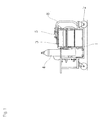
- Fig. 1 is a front view of a fire extinguishing apparatus according to an embodiment
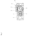
- Fig. 2 is a plan view thereof
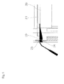
- Fig. 3 is a piping system view.
- reference sign 1 denotes a movable carriage including running wheels 2, on which a sand container 3, nitrogen gas cylinders 4, and an ejector 5 are mounted.
- the sand container 3 is a drum container, in which expanded vermiculite as fire extinguishing sand is housed.
- the capacity of a general drum container is 200 L, but to prevent a blocking phenomenon from occurring inside, the filling amount of the expanded vermiculite is preferably less than the capacity.
- the expanded vermiculite has low bulk specific gravity and has a feature of expanding and forming an air blocking layer when heat is applied. Based on an experiment, depositing the vermiculite as high as about 3 cm can bring about a sufficient fire extinguishing effect.
- a particle diameter of the fire extinguishing sand is preferably about 3 to 5 mm.
- the fire extinguishing sand is not limited to the expanded vermiculite.
- the two nitrogen gas cylinders 4 are mounted.
- the reason for this is to avoid danger in which gas pressure decreases during a fire extinguishing work to disable fire extinction, and one of them is a spare cylinder.
- a commercial product with a capacity of 47 L and with primary pressure of 14.7 MPa can be used.
- These nitrogen gas cylinders 4 are connected to a decompression valve 6 illustrated in Fig. 3 , and nitrogen gas is decompressed to about 0.3 MPa and is then supplied to the ejector 5.
- the ejector 5 generates negative pressure due to the supplied nitrogen gas stream.
- a suction tube 7 to a base portion of the ejector 5 and inserting a tip end thereof deeply into the sand container 3, the fire extinguishing sand can be sucked from the inside of the sand container 3.
- a delivery tube 8 To a tip end of the ejector 5 is connected a delivery tube 8, and the sucked fire extinguishing sand is delivered to the delivery tube 8 along with the nitrogen gas stream.
- a metallic pipe 9 and a nozzle 10 to a tip end of the delivery tube 8 are connected to a metallic pipe 9 and a nozzle 10, and the fire extinguishing sand as well as the nitrogen gas can be sprayed from a tip end of the nozzle 10.
- the flow rate of the nitrogen gas to be supplied to the ejector 5 is preferably 700 L per minute or more.
- the suction tube 7 is preferably arranged at a position deviating to one side from the center of the sand container 3. Locating the suction tube 7 at the center of the sand container 3 easily causes blocking because the suction tube 7 sucks the fire extinguishing sand uniformly from the periphery, but locating the suction tube 7 at an eccentric position hardly causes blocking because of the imbalance and enables the fire extinguishing sand to be delivered continuously.
- a sand inlet 12 On a lid plate 11 of the sand container 3 is formed a sand inlet 12 as illustrated in Fig. 2 . Both the lid plate 11 and the sand inlet 12 are airtight lids with packing and can be opened as needed. Accordingly, the sand inlet 12 can be opened to refill the sand container 3 with the fire extinguishing sand during the fire extinguishing work, and a shortage of sand does not occur during the fire extinguishing work.
- the fire extinguishing sand represented by expanded vermiculite tends to be solidified by atmospheric humidity and may not be sucked smoothly by the suction tube 7 when the sand is lowered in dispersion property due to moisture absorption.
- the fire extinguishing apparatus of this kind is not used for a long time and would be worthless if the fire extinguishing sand was solid in case of fire.
- the inside of the sand container 3 is filled with the nitrogen gas, and troubles such as solidification and deterioration of the fire extinguishing sand can be prevented reliably.
- the lid plate 11 of the sand container 3 is provided with a relief valve 15, and the relief valve 15 lets the nitrogen gas outside in a case in which the internal pressure rises abnormally to avoid danger of a breach.
- Fig. 4 illustrates a state of using the fire extinguishing apparatus according to the present invention for fire extinction of a battery system using sodium-sulfur batteries.
- the battery charge system using the sodium-sulfur batteries is constituted by combination of multiple battery modules 20 in accordance with the charging capacity.
- Each of the battery modules 20 is a rectangular solid having a width and a depth of approximately 1.5 m and a height of approximately 0.8 m, and the battery modules 20 are housed in a rack 21 having a total height of nearly 5 m in a multistage manner.
- a flattened upper space 23 having a height of no more than 5 cm or so is formed between a floor plate 22 of the rack 21 and a ceiling surface of the battery module 20.
- Doors 24 are arranged on a front face of the rack 21, and horizontally long openings 25 are formed at positions corresponding to the respective upper spaces 23.
- the nozzle 10 attached to a tip end of the metallic pipe 9 is inserted into the opening 25 of the door 24, and the fire extinguishing sand is emitted into the upper space 23.
- the nozzle 10 includes a guide plate 27 having a positioning recess 26 on a lower surface thereof, and by inserting the nozzle 10 into the opening 25 and then pushing the nozzle 10 to a back side, the nozzle 10 can be positioned at a position at which the positioning recess 26 is engaged with a lower edge of the opening 25. Accordingly, a reliable fire extinguishing work can be performed even in a case in which the firing source is located at a high position.
- the metallic pipes 9 are prepared so that as many metallic pipes 9 as the appropriate number can be sequentially added and used in accordance with the height of the firing source. To do so, it is preferable to mount several metallic pipes 9 on the movable carriage 1 so that the metallic pipes 9 can be used immediately.
- the fire extinguishing apparatus configured as above, by moving the fire extinguishing apparatus close to the firing source and an opening valve of the nitrogen gas cylinder 4 in case of fire, the ejector 5 generates negative pressure due to the nitrogen gas stream and sucks the fire extinguishing sand from the inside of the sand container 3.
- the sucked fire extinguishing sand is delivered to the delivery tube 8 along with the nitrogen gas stream and can be sprayed from the tip end of the nozzle 10 together with the nitrogen gas.
- the fire extinguishing sand covers a surface of an object under fire extinction to shut off air, and the fire can be extinguished.
- the sand inlet 12 can be opened to refill the sand container 3 with the fire extinguishing sand even during the fire extinguishing work, a shortage of sand does not occur during the fire extinguishing work.
- the fire extinguishing apparatus according to the present invention does not need to use a pressure container as the sand container 3, the fire extinguishing apparatus is low in manufacturing cost and is easy to handle.
- the fire extinguishing apparatus according to the present invention is suitable for fire extinction for a battery system using sodium-sulfur batteries, it is to be understood that the fire extinguishing apparatus can be used for other general fire.
Landscapes
- Health & Medical Sciences (AREA)
- Public Health (AREA)
- Business, Economics & Management (AREA)
- Emergency Management (AREA)
- Fire-Extinguishing By Fire Departments, And Fire-Extinguishing Equipment And Control Thereof (AREA)
- Secondary Cells (AREA)
Abstract
Description
- The present invention relates to a fire extinguishing apparatus suitable for fire extinction for a fire extinguishing object such as a high-temperature operable battery.
- A battery system using sodium-sulfur batteries is constituted by combination of multiple battery modules each housing hundreds of battery cells in a thermal insulating enclosure. In case of firing of such a battery module, hot molten material of sodium and sulfur blows out to a ceiling surface of the thermal insulating enclosure, and when the hot molten material contacts air, a severe oxidation reaction occurs, which may cause enlargement of the fire. Since fire extinction with water is impossible due to existence of sodium, fire extinction by suffocation, in which air is shut off with use of fire extinguishing sand, is required. This battery charge system using the sodium-sulfur batteries may be several meters in height in a case of adopting a structure in which a plurality of battery modules are piled. Accordingly, a fire extinguishing apparatus is required to have ability to raise the fire extinguishing sand as high as several meters and spray it.
-
Patent Document 1 filed by the present applicant describes a fire extinguishing apparatus adapted to spray ceramic particles to an object under fire extinction. This apparatus has a structure in which the ceramic particles are housed in a storage tank and are delivered from a bottom portion of the storage tank with use of gas pressure applied to the storage tank from a gas cylinder. - However, in this apparatus, the storage tank has to be a pressure container since the storage tank needs to be pressurized at high pressure, which causes a problem of an increase in manufacturing cost and non-easy handling. Also, since the storage tank cannot be refilled with fire extinguishing sand during a fire extinguishing work, the amount of the fire extinguishing sand may be insufficient depending on the fire scale.
- Patent Document 1:
JP 06-269509 A - An object of the present invention is to solve the aforementioned conventional problems and to provide a fire extinguishing apparatus which is inexpensive in manufacturing cost, is easy to handle, and enables a storage tank to be refilled with fire extinguishing sand during a fire extinguishing work.
- To solve the above problems, a fire extinguishing apparatus according to the present invention includes a sand container in which fire extinguishing sand is housed, a nitrogen gas cylinder, and an ejector to which nitrogen gas taken out via a decompression valve from the nitrogen gas cylinder is supplied. The ejector is connected to a suction tube sucking the fire extinguishing sand from the sand container with use of negative pressure generated due to a nitrogen gas stream and a delivery tube delivering the sucked fire extinguishing sand as well as the nitrogen gas. The sand container has a lid plate thereof provided with a sand inlet enabling opening and closing.
- Meanwhile, as in
claim 2, the suction tube is preferably arranged at a position deviating from a center of the sand container. Also, as inclaim 3, the fire extinguishing apparatus preferably includes a nitrogen enclosing tube further reducing pressure of the nitrogen gas taken out via the decompression valve from the nitrogen gas cylinder and supplying the nitrogen gas into an inside of the sand container. Also, as inclaim 4, the fire extinguishing sand is preferably expanded vermiculite. Further, as in claim 5, the sand container, the nitrogen gas cylinder, and the ejector are preferably mounted on a movable carriage. - The fire extinguishing apparatus according to the present invention generates the negative pressure in the ejector due to the nitrogen gas stream, sucks the fire extinguishing sand from the sand container with use of this negative pressure, and delivers the fire extinguishing sand as well as the nitrogen gas. Thus, the sand container does not need to be a pressure container, and the fire extinguishing apparatus is easy to manufacture and handle. Also, since the sand container can be refilled with the fire extinguishing sand through the sand inlet during a fire extinguishing work as needed, a shortage of sand does not occur during the fire extinguishing work.
- As in
claim 2, since the suction tube is arranged at the position deviating from the center of the sand container, a blocking phenomenon of the fire extinguishing sand hardly occurs in the inside of the sand container, and the fire extinguishing sand can be delivered continuously. - As in
claim 3, since the fire extinguishing apparatus includes the nitrogen enclosing tube further reducing pressure of the nitrogen gas taken out via the decompression valve from the nitrogen gas cylinder and supplying the nitrogen gas into the inside of the sand container, the fire extinguishing sand stored in the inside of the sand container will not contact air, which can prevent moisture absorption and deterioration of the fire extinguishing sand. - As in
claim 4, since the fire extinguishing sand is the expanded vermiculite, the fire extinguishing sand is easily sprayed to a high position along with the nitrogen gas stream due to low bulk specific gravity and easily forms an air blocking layer at a deposited position. Accordingly, an excellent fire extinguishing effect can be obtained even in a case in which a firing source is located at a high position. - Further, as in claim 5, since the sand container, the nitrogen gas cylinder, and the ejector are mounted on the movable carriage, the fire extinguishing apparatus can be moved easily when a fire occurs. Also, since the fire extinguishing apparatus does not require a power source, the fire extinguishing work can be started immediately.
-
-
Fig. 1 is a front view of a fire extinguishing apparatus according to an embodiment. -
Fig. 2 is a plan view of the fire extinguishing apparatus according to the embodiment. -
Fig. 3 is a piping system view. -
Fig. 4 describes a use state of the fire extinguishing apparatus according to the present invention. -
Fig. 5 is an enlarged view of a nozzle part. - Hereinbelow, preferred embodiments of the present invention will be described.
-
Fig. 1 is a front view of a fire extinguishing apparatus according to an embodiment,Fig. 2 is a plan view thereof, andFig. 3 is a piping system view. InFigs. 1 and2 ,reference sign 1 denotes a movable carriage includingrunning wheels 2, on which asand container 3,nitrogen gas cylinders 4, and an ejector 5 are mounted. - In the present embodiment, the
sand container 3 is a drum container, in which expanded vermiculite as fire extinguishing sand is housed. The capacity of a general drum container is 200 L, but to prevent a blocking phenomenon from occurring inside, the filling amount of the expanded vermiculite is preferably less than the capacity. The expanded vermiculite has low bulk specific gravity and has a feature of expanding and forming an air blocking layer when heat is applied. Based on an experiment, depositing the vermiculite as high as about 3 cm can bring about a sufficient fire extinguishing effect. A particle diameter of the fire extinguishing sand is preferably about 3 to 5 mm. The reason for this is that the sand with a shorter particle diameter than it may be difficult to fly on gas stream while the sand with a longer particle diameter than it may cause a nozzle or the like to be clogged. However, the fire extinguishing sand is not limited to the expanded vermiculite. - In the present embodiment, the two
nitrogen gas cylinders 4 are mounted. The reason for this is to avoid danger in which gas pressure decreases during a fire extinguishing work to disable fire extinction, and one of them is a spare cylinder. As each of thenitrogen gas cylinders 4, a commercial product with a capacity of 47 L and with primary pressure of 14.7 MPa can be used. Thesenitrogen gas cylinders 4 are connected to adecompression valve 6 illustrated inFig. 3 , and nitrogen gas is decompressed to about 0.3 MPa and is then supplied to the ejector 5. - The ejector 5 generates negative pressure due to the supplied nitrogen gas stream. Thus, by connecting a
suction tube 7 to a base portion of the ejector 5 and inserting a tip end thereof deeply into thesand container 3, the fire extinguishing sand can be sucked from the inside of thesand container 3. To a tip end of the ejector 5 is connected adelivery tube 8, and the sucked fire extinguishing sand is delivered to thedelivery tube 8 along with the nitrogen gas stream. As illustrated inFig. 4 , to a tip end of thedelivery tube 8 are connected ametallic pipe 9 and anozzle 10, and the fire extinguishing sand as well as the nitrogen gas can be sprayed from a tip end of thenozzle 10. To raise the fire extinguishing sand as high as 5 m and spray it, the flow rate of the nitrogen gas to be supplied to the ejector 5 is preferably 700 L per minute or more. - As illustrated in
Fig. 3 , thesuction tube 7 is preferably arranged at a position deviating to one side from the center of thesand container 3. Locating thesuction tube 7 at the center of thesand container 3 easily causes blocking because thesuction tube 7 sucks the fire extinguishing sand uniformly from the periphery, but locating thesuction tube 7 at an eccentric position hardly causes blocking because of the imbalance and enables the fire extinguishing sand to be delivered continuously. - On a
lid plate 11 of thesand container 3 is formed asand inlet 12 as illustrated inFig. 2 . Both thelid plate 11 and thesand inlet 12 are airtight lids with packing and can be opened as needed. Accordingly, thesand inlet 12 can be opened to refill thesand container 3 with the fire extinguishing sand during the fire extinguishing work, and a shortage of sand does not occur during the fire extinguishing work. Although such refilling during the fire extinguishing work is impossible in a conventional pressure-container-type fire extinguishing apparatus, the refilling is possible in the suction-type fire extinguishing apparatus according to the present invention, which is a great advantage for the fire extinguishing apparatus according to the present invention. - Meanwhile, the fire extinguishing sand represented by expanded vermiculite tends to be solidified by atmospheric humidity and may not be sucked smoothly by the
suction tube 7 when the sand is lowered in dispersion property due to moisture absorption. Normally, the fire extinguishing apparatus of this kind is not used for a long time and would be worthless if the fire extinguishing sand was solid in case of fire. To avoid this situation, it is preferable to bifurcate an outlet side of thedecompression valve 6, reduce the pressure by apressure regulating valve 13 to pressure slightly higher than atmospheric pressure, and supply the nitrogen gas into the inside of thesand container 3 through anitrogen enclosing tube 14 as illustrated inFig. 3 . By doing so, the inside of thesand container 3 is filled with the nitrogen gas, and troubles such as solidification and deterioration of the fire extinguishing sand can be prevented reliably. Also, thelid plate 11 of thesand container 3 is provided with arelief valve 15, and therelief valve 15 lets the nitrogen gas outside in a case in which the internal pressure rises abnormally to avoid danger of a breach. -
Fig. 4 illustrates a state of using the fire extinguishing apparatus according to the present invention for fire extinction of a battery system using sodium-sulfur batteries. The battery charge system using the sodium-sulfur batteries is constituted by combination ofmultiple battery modules 20 in accordance with the charging capacity. Each of thebattery modules 20 is a rectangular solid having a width and a depth of approximately 1.5 m and a height of approximately 0.8 m, and thebattery modules 20 are housed in arack 21 having a total height of nearly 5 m in a multistage manner. A flattenedupper space 23 having a height of no more than 5 cm or so is formed between afloor plate 22 of therack 21 and a ceiling surface of thebattery module 20. -
Doors 24 are arranged on a front face of therack 21, and horizontallylong openings 25 are formed at positions corresponding to the respectiveupper spaces 23. - As illustrated in
Fig. 4 , as manymetallic pipes 9 as the appropriate number are connected to the tip end of thedelivery tube 8 in accordance with the height of a firing source, thenozzle 10 attached to a tip end of themetallic pipe 9 is inserted into theopening 25 of thedoor 24, and the fire extinguishing sand is emitted into theupper space 23. Meanwhile, thenozzle 10 includes a guide plate 27 having apositioning recess 26 on a lower surface thereof, and by inserting thenozzle 10 into theopening 25 and then pushing thenozzle 10 to a back side, thenozzle 10 can be positioned at a position at which thepositioning recess 26 is engaged with a lower edge of theopening 25. Accordingly, a reliable fire extinguishing work can be performed even in a case in which the firing source is located at a high position. - In this manner, the
metallic pipes 9 are prepared so that as manymetallic pipes 9 as the appropriate number can be sequentially added and used in accordance with the height of the firing source. To do so, it is preferable to mount severalmetallic pipes 9 on themovable carriage 1 so that themetallic pipes 9 can be used immediately. - In the fire extinguishing apparatus configured as above, by moving the fire extinguishing apparatus close to the firing source and an opening valve of the
nitrogen gas cylinder 4 in case of fire, the ejector 5 generates negative pressure due to the nitrogen gas stream and sucks the fire extinguishing sand from the inside of thesand container 3. The sucked fire extinguishing sand is delivered to thedelivery tube 8 along with the nitrogen gas stream and can be sprayed from the tip end of thenozzle 10 together with the nitrogen gas. The fire extinguishing sand covers a surface of an object under fire extinction to shut off air, and the fire can be extinguished. As described above, since thesand inlet 12 can be opened to refill thesand container 3 with the fire extinguishing sand even during the fire extinguishing work, a shortage of sand does not occur during the fire extinguishing work. - Also, since the fire extinguishing apparatus according to the present invention does not need to use a pressure container as the
sand container 3, the fire extinguishing apparatus is low in manufacturing cost and is easy to handle. Although the fire extinguishing apparatus according to the present invention is suitable for fire extinction for a battery system using sodium-sulfur batteries, it is to be understood that the fire extinguishing apparatus can be used for other general fire. -
- 1
- Movable carriage
- 2
- Running wheel
- 3
- Sand container
- 4
- Nitrogen gas cylinder
- 5
- Ejector
- 6
- Decompression valve
- 7
- Suction tube
- 8
- Delivery tube
- 9
- Pipe
- 10
- Nozzle
- 11
- Lid plate
- 12
- Sand inlet
- 13
- Pressure regulating valve
- 14
- Nitrogen enclosing tube
- 15
- Relief valve
- 20
- Battery module
- 21
- Rack
- 22
- Floor plate
- 23
- Upper space
- 24
- Door
- 25
- Opening
- 26
- Positioning recess
- 27
- Guide plate
Claims (5)
- A fire extinguishing apparatus comprising:a sand container in which fire extinguishing sand is housed;a nitrogen gas cylinder; andan ejector to which nitrogen gas taken out via a decompression valve from the nitrogen gas cylinder is supplied,wherein the ejector is connected to a suction tube sucking the fire extinguishing sand from the sand container with use of negative pressure generated due to a nitrogen gas stream and a delivery tube delivering the sucked fire extinguishing sand as well as the nitrogen gas, andwherein the sand container has a lid plate thereof provided with a sand inlet enabling opening and closing.
- The fire extinguishing apparatus according to claim 1, wherein the suction tube is arranged at a position deviating from a center of the sand container.
- The fire extinguishing apparatus according to claim 1, further comprising a nitrogen enclosing tube further reducing pressure of the nitrogen gas taken out via the decompression valve from the nitrogen gas cylinder and supplying the nitrogen gas into an inside of the sand container.
- The fire extinguishing apparatus according to claim 1, wherein the fire extinguishing sand is expanded vermiculite.
- The fire extinguishing apparatus according to claim 1, wherein the sand container, the nitrogen gas cylinder, and the ejector are mounted on a movable carriage.
Applications Claiming Priority (2)
| Application Number | Priority Date | Filing Date | Title |
|---|---|---|---|
| JP2012157257 | 2012-07-13 | ||
| PCT/JP2013/067533 WO2014010423A1 (en) | 2012-07-13 | 2013-06-26 | Fire extinguisher |
Publications (3)
| Publication Number | Publication Date |
|---|---|
| EP2873441A1 true EP2873441A1 (en) | 2015-05-20 |
| EP2873441A4 EP2873441A4 (en) | 2015-12-09 |
| EP2873441B1 EP2873441B1 (en) | 2018-03-14 |
Family
ID=49915887
Family Applications (1)
| Application Number | Title | Priority Date | Filing Date |
|---|---|---|---|
| EP13816905.7A Active EP2873441B1 (en) | 2012-07-13 | 2013-06-26 | Fire extinguisher |
Country Status (5)
| Country | Link |
|---|---|
| US (1) | US9522291B2 (en) |
| EP (1) | EP2873441B1 (en) |
| JP (1) | JPWO2014010423A1 (en) |
| CN (1) | CN104334235B (en) |
| WO (1) | WO2014010423A1 (en) |
Families Citing this family (15)
| Publication number | Priority date | Publication date | Assignee | Title |
|---|---|---|---|---|
| CN104027923A (en) * | 2014-07-04 | 2014-09-10 | 安庆市鸿裕工业产品设计有限公司 | Yellow sand powder fire extinguishing device |
| CN105148433A (en) * | 2015-10-14 | 2015-12-16 | 何勇志 | Sandblast fire-extinguishing device |
| DE102016206851B3 (en) | 2016-04-22 | 2017-10-26 | Audi Ag | Extinguishing method and extinguishing device for introducing at least one extinguishing agent into a battery |
| CN105833449A (en) * | 2016-04-29 | 2016-08-10 | 羊丁 | Automatic sand blasting fire-fighting robot for high-speed gas |
| CA3027323C (en) * | 2016-06-13 | 2022-09-06 | Koatsu Co., Ltd. | Fire extinguisher |
| CN106823204B (en) * | 2017-02-15 | 2022-04-22 | 应急管理部天津消防研究所 | A sand positive pressure jet fire extinguishing system and its realization method |
| CN107583220B (en) * | 2017-10-26 | 2022-11-22 | 北京安泰德科技有限公司 | Split type multi-opening fire-fighting equipment placing box capable of automatically filling sand |
| US20190290950A1 (en) * | 2018-03-26 | 2019-09-26 | Kidde Technologies, Inc. | Vermiculite based fire suppression agent |
| TWI666848B (en) * | 2018-09-12 | 2019-07-21 | 財團法人工業技術研究院 | Fire control device for power storage system and operating method thereof |
| CN110624188A (en) * | 2019-09-27 | 2019-12-31 | 东莞宜安科技股份有限公司 | Rapid fire extinguishing device |
| KR102343812B1 (en) * | 2019-11-20 | 2021-12-27 | 이종관 | Metal fire extinguishers |
| CN111346331B (en) * | 2020-03-17 | 2021-04-23 | 全恒国际创意(深圳)有限公司 | Automatic indoor fire treatment device |
| CN111672041A (en) * | 2020-06-19 | 2020-09-18 | 哈尔滨市三棵中药材市场太清参茸行 | Electric wire fire-catching sand-blasting fire-extinguishing device |
| CN112023303B (en) * | 2020-09-10 | 2021-05-11 | 宁德师范学院 | An automatic fire extinguishing device suitable for electrical equipment |
| CN114807537A (en) * | 2022-02-26 | 2022-07-29 | 苏州民生电热工程有限公司 | Fire extinguishing and flue gas collecting mechanism of quenching oil tank |
Family Cites Families (19)
| Publication number | Priority date | Publication date | Assignee | Title |
|---|---|---|---|---|
| GB254195A (en) * | 1925-12-22 | 1926-07-01 | Kornel Szilvay | Improvements relating to the method of and apparatus for extinguishing fire |
| US1839658A (en) * | 1929-10-30 | 1932-01-05 | Gas Fire Extinguisher Corp Du | Method of extinguishing fires |
| JPS52137200A (en) * | 1976-05-10 | 1977-11-16 | Japan Synthetic Rubber Co Ltd | Fire extinguishing method and device |
| FR2371207A1 (en) * | 1976-11-22 | 1978-06-16 | Ceca Sa | Metal fires extinction with expanded graphite - prevents metal flow and gives rapid extinction |
| SU822686A1 (en) * | 1980-01-10 | 1991-11-07 | Предприятие П/Я В-2679 | Method of preparing vermiculite for extinguishing sodium fires |
| JPH03100222U (en) * | 1990-01-30 | 1991-10-21 | ||
| JPH04300564A (en) * | 1991-03-28 | 1992-10-23 | Ngk Insulators Ltd | Extinguishing agent and extinguishing device |
| JP2703430B2 (en) * | 1991-09-26 | 1998-01-26 | 日本碍子株式会社 | Fire extinguisher in sodium-sulfur battery |
| JP2703431B2 (en) * | 1991-09-26 | 1998-01-26 | 日本碍子株式会社 | Fire extinguisher in sodium-sulfur battery |
| JPH06269509A (en) * | 1993-03-17 | 1994-09-27 | Ngk Insulators Ltd | Sprikler for fire extinguishing agents |
| JP2772464B2 (en) * | 1993-10-22 | 1998-07-02 | 昭和炭酸株式会社 | Powder supply unit |
| JPH09653A (en) * | 1995-06-23 | 1997-01-07 | Hitachi Ltd | How to extinguish sodium flame |
| JPH09154971A (en) * | 1995-12-01 | 1997-06-17 | Hatsuta Seisakusho:Kk | Fire extinguisher |
| US5810089A (en) * | 1996-04-19 | 1998-09-22 | Task Force Tips, Inc. | Portable firefighting apparatus with integral control valve-handle |
| JP3100222U (en) | 2003-09-03 | 2004-05-13 | 株式会社安眠 | pillow |
| JP4601343B2 (en) * | 2004-07-12 | 2010-12-22 | 芦森工業株式会社 | Fire extinguisher |
| DE102006019739B4 (en) * | 2006-04-28 | 2008-07-10 | Patentverwertung GbR (vertretungsberchtigte Gesellschafter: Bärbel Knopf, Fischersteeg 11 | Fire extinguishing system and method of use |
| CN2936308Y (en) * | 2006-05-31 | 2007-08-22 | 天津市三源电力设备制造有限公司 | Movable fire-fighting sand box |
| CN201537338U (en) * | 2009-12-01 | 2010-08-04 | 蒋夫志 | Fire-extinguishing sand trolley for fire protection |
-
2013
- 2013-06-26 CN CN201380028977.8A patent/CN104334235B/en active Active
- 2013-06-26 WO PCT/JP2013/067533 patent/WO2014010423A1/en not_active Ceased
- 2013-06-26 EP EP13816905.7A patent/EP2873441B1/en active Active
- 2013-06-26 JP JP2014524729A patent/JPWO2014010423A1/en active Pending
-
2014
- 2014-12-05 US US14/561,343 patent/US9522291B2/en active Active
Also Published As
| Publication number | Publication date |
|---|---|
| WO2014010423A1 (en) | 2014-01-16 |
| JPWO2014010423A1 (en) | 2016-06-23 |
| CN104334235B (en) | 2016-12-14 |
| EP2873441A4 (en) | 2015-12-09 |
| US20150083446A1 (en) | 2015-03-26 |
| US9522291B2 (en) | 2016-12-20 |
| EP2873441B1 (en) | 2018-03-14 |
| CN104334235A (en) | 2015-02-04 |
Similar Documents
| Publication | Publication Date | Title |
|---|---|---|
| US9522291B2 (en) | Fire extinguishing apparatus | |
| CN110193154A (en) | The comprehensive fire fighting extinguisher of container-type lithium ion battery energy storage system | |
| WO2020133678A1 (en) | Fire protection fluid storage device for battery pack | |
| CN101972577B (en) | Mining explosion-proof dust remover | |
| CN111384341A (en) | Lithium battery box with fireproof function and using method thereof | |
| CN108544961A (en) | Battery for electric automobile inn | |
| WO2009008047A1 (en) | Device for charging dry air or nitrogen gas into semiconductor wafer storage container and wafer static charge removing apparatus utilizing the device | |
| CN106450472A (en) | Multifunctional efficient protective storage box for lithium batteries | |
| CN219783608U (en) | Energy storage battery cluster with fire protection system and energy storage container | |
| EP2873442B1 (en) | Fire-extinguisher method | |
| CN218220892U (en) | Pressure storage type fire extinguishing device | |
| CN118219907A (en) | Electricity changing cabinet | |
| CN102569694A (en) | Anti-explosion device for storage battery convey car | |
| CN212062490U (en) | Lithium cell production is with fire prevention conveyer | |
| CN208541724U (en) | Fire extinguishing device and fire extinguishing system for battery pack | |
| CN220632825U (en) | Lithium battery fire extinguishing device | |
| CN115228010A (en) | An explosion-proof storage and transportation device for aviation dangerous goods | |
| KR20140003768A (en) | Device for storage of gas | |
| CN211238360U (en) | Battery flame retardant structure and battery | |
| KR101207930B1 (en) | Pearlite top up system and method of the liquefied gas storage tank | |
| CN208081680U (en) | A kind of small-sized extinguishing device of gas station's security against fire | |
| CN208119972U (en) | A kind of fire prevention liquid dish for lithium battery storage | |
| CN223990935U (en) | Quick filling device for filling oil into power generator of expressway tunnel substation | |
| CN222592128U (en) | A portable protection device | |
| CN224036542U (en) | A battery storage system |
Legal Events
| Date | Code | Title | Description |
|---|---|---|---|
| PUAI | Public reference made under article 153(3) epc to a published international application that has entered the european phase |
Free format text: ORIGINAL CODE: 0009012 |
|
| 17P | Request for examination filed |
Effective date: 20141216 |
|
| AK | Designated contracting states |
Kind code of ref document: A1 Designated state(s): AL AT BE BG CH CY CZ DE DK EE ES FI FR GB GR HR HU IE IS IT LI LT LU LV MC MK MT NL NO PL PT RO RS SE SI SK SM TR |
|
| AX | Request for extension of the european patent |
Extension state: BA ME |
|
| DAX | Request for extension of the european patent (deleted) | ||
| REG | Reference to a national code |
Ref country code: DE Ref legal event code: R079 Ref document number: 602013034487 Country of ref document: DE Free format text: PREVIOUS MAIN CLASS: A62C0013680000 Ipc: A62C0013700000 |
|
| RA4 | Supplementary search report drawn up and despatched (corrected) |
Effective date: 20151111 |
|
| RIC1 | Information provided on ipc code assigned before grant |
Ipc: A62C 13/70 20060101AFI20151105BHEP Ipc: A62C 13/72 20060101ALI20151105BHEP Ipc: A62C 99/00 20100101ALI20151105BHEP Ipc: A62C 3/16 20060101ALI20151105BHEP Ipc: A62C 3/06 20060101ALI20151105BHEP |
|
| 17Q | First examination report despatched |
Effective date: 20170531 |
|
| GRAP | Despatch of communication of intention to grant a patent |
Free format text: ORIGINAL CODE: EPIDOSNIGR1 |
|
| INTG | Intention to grant announced |
Effective date: 20170921 |
|
| RIN1 | Information on inventor provided before grant (corrected) |
Inventor name: FUKUHARA, MOTOHIRO |
|
| GRAS | Grant fee paid |
Free format text: ORIGINAL CODE: EPIDOSNIGR3 |
|
| GRAA | (expected) grant |
Free format text: ORIGINAL CODE: 0009210 |
|
| AK | Designated contracting states |
Kind code of ref document: B1 Designated state(s): AL AT BE BG CH CY CZ DE DK EE ES FI FR GB GR HR HU IE IS IT LI LT LU LV MC MK MT NL NO PL PT RO RS SE SI SK SM TR |
|
| REG | Reference to a national code |
Ref country code: GB Ref legal event code: FG4D |
|
| REG | Reference to a national code |
Ref country code: CH Ref legal event code: EP Ref country code: AT Ref legal event code: REF Ref document number: 978274 Country of ref document: AT Kind code of ref document: T Effective date: 20180315 |
|
| REG | Reference to a national code |
Ref country code: IE Ref legal event code: FG4D |
|
| REG | Reference to a national code |
Ref country code: DE Ref legal event code: R096 Ref document number: 602013034487 Country of ref document: DE |
|
| REG | Reference to a national code |
Ref country code: NL Ref legal event code: MP Effective date: 20180314 |
|
| REG | Reference to a national code |
Ref country code: LT Ref legal event code: MG4D |
|
| PG25 | Lapsed in a contracting state [announced via postgrant information from national office to epo] |
Ref country code: NO Free format text: LAPSE BECAUSE OF FAILURE TO SUBMIT A TRANSLATION OF THE DESCRIPTION OR TO PAY THE FEE WITHIN THE PRESCRIBED TIME-LIMIT Effective date: 20180614 Ref country code: FI Free format text: LAPSE BECAUSE OF FAILURE TO SUBMIT A TRANSLATION OF THE DESCRIPTION OR TO PAY THE FEE WITHIN THE PRESCRIBED TIME-LIMIT Effective date: 20180314 Ref country code: HR Free format text: LAPSE BECAUSE OF FAILURE TO SUBMIT A TRANSLATION OF THE DESCRIPTION OR TO PAY THE FEE WITHIN THE PRESCRIBED TIME-LIMIT Effective date: 20180314 Ref country code: CY Free format text: LAPSE BECAUSE OF FAILURE TO SUBMIT A TRANSLATION OF THE DESCRIPTION OR TO PAY THE FEE WITHIN THE PRESCRIBED TIME-LIMIT Effective date: 20180314 Ref country code: LT Free format text: LAPSE BECAUSE OF FAILURE TO SUBMIT A TRANSLATION OF THE DESCRIPTION OR TO PAY THE FEE WITHIN THE PRESCRIBED TIME-LIMIT Effective date: 20180314 |
|
| REG | Reference to a national code |
Ref country code: AT Ref legal event code: MK05 Ref document number: 978274 Country of ref document: AT Kind code of ref document: T Effective date: 20180314 |
|
| PG25 | Lapsed in a contracting state [announced via postgrant information from national office to epo] |
Ref country code: BG Free format text: LAPSE BECAUSE OF FAILURE TO SUBMIT A TRANSLATION OF THE DESCRIPTION OR TO PAY THE FEE WITHIN THE PRESCRIBED TIME-LIMIT Effective date: 20180614 Ref country code: GR Free format text: LAPSE BECAUSE OF FAILURE TO SUBMIT A TRANSLATION OF THE DESCRIPTION OR TO PAY THE FEE WITHIN THE PRESCRIBED TIME-LIMIT Effective date: 20180615 Ref country code: RS Free format text: LAPSE BECAUSE OF FAILURE TO SUBMIT A TRANSLATION OF THE DESCRIPTION OR TO PAY THE FEE WITHIN THE PRESCRIBED TIME-LIMIT Effective date: 20180314 Ref country code: SE Free format text: LAPSE BECAUSE OF FAILURE TO SUBMIT A TRANSLATION OF THE DESCRIPTION OR TO PAY THE FEE WITHIN THE PRESCRIBED TIME-LIMIT Effective date: 20180314 Ref country code: LV Free format text: LAPSE BECAUSE OF FAILURE TO SUBMIT A TRANSLATION OF THE DESCRIPTION OR TO PAY THE FEE WITHIN THE PRESCRIBED TIME-LIMIT Effective date: 20180314 |
|
| PG25 | Lapsed in a contracting state [announced via postgrant information from national office to epo] |
Ref country code: PL Free format text: LAPSE BECAUSE OF FAILURE TO SUBMIT A TRANSLATION OF THE DESCRIPTION OR TO PAY THE FEE WITHIN THE PRESCRIBED TIME-LIMIT Effective date: 20180314 Ref country code: NL Free format text: LAPSE BECAUSE OF FAILURE TO SUBMIT A TRANSLATION OF THE DESCRIPTION OR TO PAY THE FEE WITHIN THE PRESCRIBED TIME-LIMIT Effective date: 20180314 Ref country code: IT Free format text: LAPSE BECAUSE OF FAILURE TO SUBMIT A TRANSLATION OF THE DESCRIPTION OR TO PAY THE FEE WITHIN THE PRESCRIBED TIME-LIMIT Effective date: 20180314 Ref country code: EE Free format text: LAPSE BECAUSE OF FAILURE TO SUBMIT A TRANSLATION OF THE DESCRIPTION OR TO PAY THE FEE WITHIN THE PRESCRIBED TIME-LIMIT Effective date: 20180314 Ref country code: AL Free format text: LAPSE BECAUSE OF FAILURE TO SUBMIT A TRANSLATION OF THE DESCRIPTION OR TO PAY THE FEE WITHIN THE PRESCRIBED TIME-LIMIT Effective date: 20180314 Ref country code: RO Free format text: LAPSE BECAUSE OF FAILURE TO SUBMIT A TRANSLATION OF THE DESCRIPTION OR TO PAY THE FEE WITHIN THE PRESCRIBED TIME-LIMIT Effective date: 20180314 Ref country code: ES Free format text: LAPSE BECAUSE OF FAILURE TO SUBMIT A TRANSLATION OF THE DESCRIPTION OR TO PAY THE FEE WITHIN THE PRESCRIBED TIME-LIMIT Effective date: 20180314 |
|
| PG25 | Lapsed in a contracting state [announced via postgrant information from national office to epo] |
Ref country code: CZ Free format text: LAPSE BECAUSE OF FAILURE TO SUBMIT A TRANSLATION OF THE DESCRIPTION OR TO PAY THE FEE WITHIN THE PRESCRIBED TIME-LIMIT Effective date: 20180314 Ref country code: SK Free format text: LAPSE BECAUSE OF FAILURE TO SUBMIT A TRANSLATION OF THE DESCRIPTION OR TO PAY THE FEE WITHIN THE PRESCRIBED TIME-LIMIT Effective date: 20180314 Ref country code: SM Free format text: LAPSE BECAUSE OF FAILURE TO SUBMIT A TRANSLATION OF THE DESCRIPTION OR TO PAY THE FEE WITHIN THE PRESCRIBED TIME-LIMIT Effective date: 20180314 Ref country code: AT Free format text: LAPSE BECAUSE OF FAILURE TO SUBMIT A TRANSLATION OF THE DESCRIPTION OR TO PAY THE FEE WITHIN THE PRESCRIBED TIME-LIMIT Effective date: 20180314 |
|
| REG | Reference to a national code |
Ref country code: DE Ref legal event code: R097 Ref document number: 602013034487 Country of ref document: DE |
|
| PG25 | Lapsed in a contracting state [announced via postgrant information from national office to epo] |
Ref country code: PT Free format text: LAPSE BECAUSE OF FAILURE TO SUBMIT A TRANSLATION OF THE DESCRIPTION OR TO PAY THE FEE WITHIN THE PRESCRIBED TIME-LIMIT Effective date: 20180716 |
|
| PLBE | No opposition filed within time limit |
Free format text: ORIGINAL CODE: 0009261 |
|
| STAA | Information on the status of an ep patent application or granted ep patent |
Free format text: STATUS: NO OPPOSITION FILED WITHIN TIME LIMIT |
|
| PG25 | Lapsed in a contracting state [announced via postgrant information from national office to epo] |
Ref country code: DK Free format text: LAPSE BECAUSE OF FAILURE TO SUBMIT A TRANSLATION OF THE DESCRIPTION OR TO PAY THE FEE WITHIN THE PRESCRIBED TIME-LIMIT Effective date: 20180314 |
|
| REG | Reference to a national code |
Ref country code: CH Ref legal event code: PL |
|
| 26N | No opposition filed |
Effective date: 20181217 |
|
| GBPC | Gb: european patent ceased through non-payment of renewal fee |
Effective date: 20180626 |
|
| PG25 | Lapsed in a contracting state [announced via postgrant information from national office to epo] |
Ref country code: SI Free format text: LAPSE BECAUSE OF FAILURE TO SUBMIT A TRANSLATION OF THE DESCRIPTION OR TO PAY THE FEE WITHIN THE PRESCRIBED TIME-LIMIT Effective date: 20180314 |
|
| REG | Reference to a national code |
Ref country code: BE Ref legal event code: MM Effective date: 20180630 |
|
| REG | Reference to a national code |
Ref country code: IE Ref legal event code: MM4A |
|
| PG25 | Lapsed in a contracting state [announced via postgrant information from national office to epo] |
Ref country code: MC Free format text: LAPSE BECAUSE OF FAILURE TO SUBMIT A TRANSLATION OF THE DESCRIPTION OR TO PAY THE FEE WITHIN THE PRESCRIBED TIME-LIMIT Effective date: 20180314 Ref country code: LU Free format text: LAPSE BECAUSE OF NON-PAYMENT OF DUE FEES Effective date: 20180626 |
|
| PG25 | Lapsed in a contracting state [announced via postgrant information from national office to epo] |
Ref country code: IE Free format text: LAPSE BECAUSE OF NON-PAYMENT OF DUE FEES Effective date: 20180626 Ref country code: CH Free format text: LAPSE BECAUSE OF NON-PAYMENT OF DUE FEES Effective date: 20180630 Ref country code: LI Free format text: LAPSE BECAUSE OF NON-PAYMENT OF DUE FEES Effective date: 20180630 Ref country code: GB Free format text: LAPSE BECAUSE OF NON-PAYMENT OF DUE FEES Effective date: 20180626 Ref country code: FR Free format text: LAPSE BECAUSE OF NON-PAYMENT OF DUE FEES Effective date: 20180630 |
|
| PG25 | Lapsed in a contracting state [announced via postgrant information from national office to epo] |
Ref country code: BE Free format text: LAPSE BECAUSE OF NON-PAYMENT OF DUE FEES Effective date: 20180630 |
|
| PG25 | Lapsed in a contracting state [announced via postgrant information from national office to epo] |
Ref country code: MT Free format text: LAPSE BECAUSE OF NON-PAYMENT OF DUE FEES Effective date: 20180626 |
|
| PG25 | Lapsed in a contracting state [announced via postgrant information from national office to epo] |
Ref country code: TR Free format text: LAPSE BECAUSE OF FAILURE TO SUBMIT A TRANSLATION OF THE DESCRIPTION OR TO PAY THE FEE WITHIN THE PRESCRIBED TIME-LIMIT Effective date: 20180314 |
|
| PG25 | Lapsed in a contracting state [announced via postgrant information from national office to epo] |
Ref country code: MK Free format text: LAPSE BECAUSE OF NON-PAYMENT OF DUE FEES Effective date: 20180314 Ref country code: HU Free format text: LAPSE BECAUSE OF FAILURE TO SUBMIT A TRANSLATION OF THE DESCRIPTION OR TO PAY THE FEE WITHIN THE PRESCRIBED TIME-LIMIT; INVALID AB INITIO Effective date: 20130626 |
|
| PG25 | Lapsed in a contracting state [announced via postgrant information from national office to epo] |
Ref country code: IS Free format text: LAPSE BECAUSE OF FAILURE TO SUBMIT A TRANSLATION OF THE DESCRIPTION OR TO PAY THE FEE WITHIN THE PRESCRIBED TIME-LIMIT Effective date: 20180714 |
|
| PGFP | Annual fee paid to national office [announced via postgrant information from national office to epo] |
Ref country code: DE Payment date: 20250429 Year of fee payment: 13 |