EP2873380B1 - Anvil delivery system - Google Patents
Anvil delivery system Download PDFInfo
- Publication number
- EP2873380B1 EP2873380B1 EP14192785.5A EP14192785A EP2873380B1 EP 2873380 B1 EP2873380 B1 EP 2873380B1 EP 14192785 A EP14192785 A EP 14192785A EP 2873380 B1 EP2873380 B1 EP 2873380B1
- Authority
- EP
- European Patent Office
- Prior art keywords
- anvil
- assembly
- suture
- delivery system
- head
- Prior art date
- Legal status (The legal status is an assumption and is not a legal conclusion. Google has not performed a legal analysis and makes no representation as to the accuracy of the status listed.)
- Active
Links
- 238000003780 insertion Methods 0.000 claims description 8
- 230000037431 insertion Effects 0.000 claims description 8
- 230000000694 effects Effects 0.000 claims description 2
- 238000000034 method Methods 0.000 description 14
- 238000010304 firing Methods 0.000 description 10
- 230000003872 anastomosis Effects 0.000 description 6
- 210000000056 organ Anatomy 0.000 description 6
- 210000002784 stomach Anatomy 0.000 description 4
- 210000003238 esophagus Anatomy 0.000 description 3
- 238000001356 surgical procedure Methods 0.000 description 3
- 230000000712 assembly Effects 0.000 description 2
- 238000000429 assembly Methods 0.000 description 2
- 230000009286 beneficial effect Effects 0.000 description 2
- 239000000463 material Substances 0.000 description 2
- 238000012986 modification Methods 0.000 description 2
- 230000004048 modification Effects 0.000 description 2
- 230000000717 retained effect Effects 0.000 description 2
- 238000000926 separation method Methods 0.000 description 2
- 241000894006 Bacteria Species 0.000 description 1
- 229920002799 BoPET Polymers 0.000 description 1
- 238000004891 communication Methods 0.000 description 1
- 230000002950 deficient Effects 0.000 description 1
- 230000001419 dependent effect Effects 0.000 description 1
- 238000002372 labelling Methods 0.000 description 1
- 230000014759 maintenance of location Effects 0.000 description 1
- 230000002028 premature Effects 0.000 description 1
- 238000002360 preparation method Methods 0.000 description 1
- 230000001681 protective effect Effects 0.000 description 1
- 230000000451 tissue damage Effects 0.000 description 1
- 231100000827 tissue damage Toxicity 0.000 description 1
Images


Classifications
-
- A—HUMAN NECESSITIES
- A61—MEDICAL OR VETERINARY SCIENCE; HYGIENE
- A61B—DIAGNOSIS; SURGERY; IDENTIFICATION
- A61B17/00—Surgical instruments, devices or methods, e.g. tourniquets
- A61B17/11—Surgical instruments, devices or methods, e.g. tourniquets for performing anastomosis; Buttons for anastomosis
- A61B17/115—Staplers for performing anastomosis in a single operation
- A61B17/1155—Circular staplers comprising a plurality of staples
-
- A—HUMAN NECESSITIES
- A61—MEDICAL OR VETERINARY SCIENCE; HYGIENE
- A61B—DIAGNOSIS; SURGERY; IDENTIFICATION
- A61B17/00—Surgical instruments, devices or methods, e.g. tourniquets
- A61B17/04—Surgical instruments, devices or methods, e.g. tourniquets for suturing wounds; Holders or packages for needles or suture materials
- A61B17/0469—Suturing instruments for use in minimally invasive surgery, e.g. endoscopic surgery
-
- A—HUMAN NECESSITIES
- A61—MEDICAL OR VETERINARY SCIENCE; HYGIENE
- A61B—DIAGNOSIS; SURGERY; IDENTIFICATION
- A61B17/00—Surgical instruments, devices or methods, e.g. tourniquets
- A61B17/11—Surgical instruments, devices or methods, e.g. tourniquets for performing anastomosis; Buttons for anastomosis
- A61B17/1114—Surgical instruments, devices or methods, e.g. tourniquets for performing anastomosis; Buttons for anastomosis of the digestive tract, e.g. bowels or oesophagus
-
- A—HUMAN NECESSITIES
- A61—MEDICAL OR VETERINARY SCIENCE; HYGIENE
- A61B—DIAGNOSIS; SURGERY; IDENTIFICATION
- A61B17/00—Surgical instruments, devices or methods, e.g. tourniquets
- A61B17/04—Surgical instruments, devices or methods, e.g. tourniquets for suturing wounds; Holders or packages for needles or suture materials
- A61B17/06—Needles ; Sutures; Needle-suture combinations; Holders or packages for needles or suture materials
- A61B17/06114—Packages or dispensers for needles or sutures
- A61B17/06119—Packages or dispensers for needles or sutures of cylindrical shape
- A61B17/06123—Flat cylinders, e.g. including an inner reel
-
- A—HUMAN NECESSITIES
- A61—MEDICAL OR VETERINARY SCIENCE; HYGIENE
- A61B—DIAGNOSIS; SURGERY; IDENTIFICATION
- A61B17/00—Surgical instruments, devices or methods, e.g. tourniquets
- A61B17/068—Surgical staplers, e.g. containing multiple staples or clamps
- A61B17/072—Surgical staplers, e.g. containing multiple staples or clamps for applying a row of staples in a single action, e.g. the staples being applied simultaneously
- A61B2017/07214—Stapler heads
- A61B2017/07257—Stapler heads characterised by its anvil
Definitions
- the present disclosure relates to an anvil delivery system for use with a surgical stapling device for trans-oral delivery of an anvil assembly.
- Anastomosis is the surgical joining of separate hollow organ sections to allow the sections to communicate with each other.
- an anastomosis procedure follows surgery in which a diseased or defective section of hollow tissue is removed and the remaining end sections are to be joined.
- the end sections of the hollow organ may be joined using circular, end-to-end, end-to-side, or side-to-side organ reconstruction methods.
- a circular anastomosis procedure the two ends of the organ sections are joined by means of a surgical stapling instrument which drives a circular array of staples through the organ end sections and cores and removes any overlapping tissue to free a tubular passage.
- a surgical stapling instrument which drives a circular array of staples through the organ end sections and cores and removes any overlapping tissue to free a tubular passage.
- an anvil rod having an attached anvil head is mounted to the distal end of a surgical stapling instrument shaft prior to insertion of the instrument into the tissue to be anastomosed.
- a detachable anvil rod may be mounted to the instrument subsequent to positioning of the surgical stapling instrument and the anvil assembly within respective tissue sections.
- the surgical stapling instrument and the anvil assembly are separately delivered to the operative site.
- Each tissue end section is then secured to a respective anvil or staple holding component, e.g., by a purse string suture.
- the anvil assembly is mounted to the surgical stapling instrument by inserting a mounting portion of the anvil rod within the distal end of the surgical stapling instrument so that a mounting mechanism within the surgical stapling instrument securely engages the anvil rod.
- Preparation of the tissue sections to be joined and mounting of the anvil rod to the surgical stapling instrument may be performed using minimally invasive surgical techniques, i.e., under laparoscopic guidance.
- An anvil assembly delivery system for delivering an anvil assembly trans-orally to a surgical site, e.g., the stomach, is disclosed in commonly owned U.S. Patent No. 8,109,426 .
- a guide suture is threaded through openings in the head of the anvil assembly to facilitate trans-oral insertion of the anvil assembly and to allow retrieval of the anvil assembly prior to attachment of the anvil assembly to the surgical stapling instrument.
- the guide suture may be detached from the anvil assembly by pulling the guide suture back through the openings in the anvil head.
- anvil assembly that is configured such that the guide suture remains attached to the anvil assembly until the stapling procedure is complete, i.e., after the tissue to be anastomosed has been stapled and cut.
- an anvil assembly for use with a surgical stapling instrument for performing end-to-end anastomosis of tissue.
- the anvil assembly includes an anvil center rod, and a head assembly pivotally secured to the anvil center rod about a pivot axis and movable between an operative position and a tilted position.
- the head assembly includes an anvil head and a cutting ring disposed within the anvil head. The anvil head defines first and second openings and the cutting ring defines a slot in alignment with the first and second openings.
- the anvil center rod may include first and second slide members.
- the first slide member may be pivotally connected to the head assembly on one side of the pivot axis by a first drive link and the second slide member being connected to the head assembly on the other side of the pivot axis by a second drive link.
- the first slide member may be movable in relation to the second slide member to effect movement of the head assembly between the operative position and the tilted position.
- the anvil assembly may further include a biasing member positioned to urge the first slide member in relation to the second slide member to position the head assembly in the tilted position.
- the biasing member may be positioned between the first slide member and the second slide member to urge the first and second slide members apart.
- anvil delivery system including an anvil assembly and a suture guide assembly.
- the suture guide assembly includes a guide suture secured to the head assembly and a reel assembly configured for selectively dispensing the guide suture.
- the guide suture may be received through the first opening in the anvil head, passes through the slot in the cutting ring, and extends from the second opening in the anvil head.
- the reel assembly may include a housing and a reel member rotatably received within the housing.
- the guide suture may be supported about the reel member.
- the reel member may define an annular channel for receiving the guide suture.
- the housing may define an annular cavity.
- the reel member may be rotatably supported on the housing within the annular cavity.
- the anvil delivery system may further include a tubular guide assembly for trans-oral insertion of the anvil assembly.
- the tubular guide assembly may include a flexible tube and an adapter configured for operably connecting the flexible tube to the anvil center rod.
- the tubular guide assembly may further include a retaining suture for retaining the head assembly of the anvil assembly in the tilted position. The retaining suture may be received through third and fourth openings in the anvil head and may be secured between the adapter and the flexible tube.
- proximal refers to that part or component closer to the user or operator, i.e. surgeon or clinician
- distal refers to that part or component further away from the user.
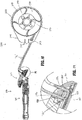
- stapling device 10 includes a proximal handle assembly 12, an elongated central body portion 14 including a curved elongated outer tube 14a, and a distal head portion 16.
- Handle assembly 12 includes a stationary handle 18, a firing trigger 20, a rotatable approximation knob 22, and an indicator 24.
- a pivotally mounted trigger lock 26 is fastened to handle assembly 12 and is manually positioned to prevent inadvertent firing of stapling device 10.
- Indicator 24 is positioned on the stationary handle 18 and includes indicia, e.g., color coding, alpha-numeric labeling, etc., to identify to a surgeon whether the device is approximated and is ready to be fired.
- Head portion 16 includes an anvil assembly 100 and a shell assembly 30.
- the structure and function of stapling device 10 will only be described to the extent necessary to fully disclose the operation of anvil assembly 100.
- U.S. Patent No. 7,364,060 (“the '060 patent").
- the surgical stapling device may be a powered (e.g., motor operated) surgical instrument, or part of a robotic surgical system, in any of the embodiments disclosed herein.
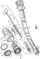
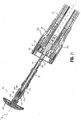
- distal end portion 16 of stapling device 10 includes shell assembly 30 which is secured to a distal end of the central body portion 14, a pusher 40 extending distally through central body portion 14, and an anvil retainer assembly 50 extending through pusher 40 and shell assembly 30.
- anvil retainer assembly 50 is operably connected to an approximation mechanism of stapling device 10 which is actuated by the rotatable approximation knob 22 ( FIG. 1 )
- pusher 40 is operably connected to a firing mechanism of stapling device 10 which is actuated by the firing trigger 20 ( FIG. 1 ).
- the approximation mechanism and/or the firing mechanism of the stapling device 10 see the '060 patent.
- Shell assembly 30 includes a shell or housing 32, a pusher back 34, a staple guide 36, a cylindrical knife 38 ( FIG. 25 ), and a plurality of staples "S".
- Shell 32 includes an outer housing portion 32a and an inner housing portion 32b ( FIG. 3 ).
- Staple guide 36 is supported in the distal end of outer housing portion 32a and includes an annular array of staple receiving pockets 36a for housing staples "S”.
- Pusher back 34 is slidably supported in shell 32 between outer housing portion 32a and inner housing portion 32b and includes a plurality of fingers 34a which are each slidably received in respective staple pockets 36a in staple guide 36.
- Pusher back 34 includes a pair of recesses 35 which receive detents 42a formed on flexible fingers 42 of a pusher 40 to secure pusher 40 to pusher back 34 such that pusher back 34 is movable with pusher 40 from a retracted position to an advanced position to eject staples "S" from staple guide 36.
- the shell assembly may be configured as a removable and replaceable assembly. In this way, after the staples are fired, the shell assembly can be replaced, providing a new set of staples, even staples of a different size or configuration, and a fresh knife.
- An elongated hollow bushing 44 is fixedly retained in inner housing portion 32b of shell 32 using, e.g., screw threads, a friction fitting, or the like.
- Bushing 44 defines a channel 45 through which anvil retainer assembly 50 and anvil center rod 160 reciprocate during approximation and separation of anvil assembly 100 and shell assembly 30.
- Bushing 44 provides additional strength to inner housing portion 32b of shell 32 to prevent separation of the anvil assembly 100 and anvil retainer assembly 50 during firing of the stapling device 10.
- Anvil retainer assembly 50 includes a two-part assembly having a body portion 52 defining a longitudinal throughbore 53 and a trocar or locking member 54 slidably received within longitudinal throughbore 53.
- Longitudinal throughbore 53 includes a stepped portion or shoulder 53a ( FIG. 3 ).
- Trocar 54 includes an annular flange or shoulder 54a on a proximal end and a blunt tip 54b on a distal end.
- Tip 54b of trocar 54 extends from the distal end of body portion 52 of anvil retainer assembly 50 and is movable within throughbore 53 of body portion 52 from an advanced position to a retracted position.
- a biasing member e.g., a coil spring 56, is positioned between annular flange 54a and shoulder 53a of longitudinal bore 53 ( FIG. 3 ). The biasing member 56 urges trocar 54 to its retracted position.
- the proximal end of trocar 54 includes a transverse slot 55 having a pin or rod 58 extending therethrough. Pin 58 is slidably positioned within longitudinal slots 55 formed in body portion 52. The distal and proximal ends of slots 55 define the advanced and retracted positions of trocar 54, respectively.
- Body portion 52 of anvil retainer assembly 50 includes an annular protrusion 60 and defines a longitudinal slot 61.
- Annular protrusion 60 facilitates attachment of anvil assembly 100 to anvil retainer assembly 50 as will be discussed in further detail below.
- a cam member 62 is pivotally supported about a pivot member 64 in slot 61 at a position proximal of pin 58.
- Cam member 62 includes a distal finger 62a having an angled face and a recess 63 positioned proximally of finger 62a for receiving pin 58 of trocar 54.
- Pin 58 is urged by coil spring 56 towards finger 62a. Engagement between the angled face of finger 62a and pin 58 urges cam member 62 to pivot about pivot member 64 to allow pin 58 to move into recess 63.
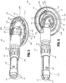
- anvil assembly 100 is configured for releasable attachment to stapling device 10 ( FIG. 1 ).
- Anvil assembly 100 includes a head assembly 102 and a rod assembly 104.
- Head assembly 102 is pivotally secured to rod assembly 104 and is configured to selectively move between a tilted position ( FIG. 5 ) and an operative position ( FIG. 21 ).
- head assembly 102 includes an anvil head 110, an anvil post 120, a cutting ring 130, a cover 140, and an anvil plate 150.
- Rod assembly 104 includes an anvil center rod 160, a first slide member 170, a second slide member 180, first and second link members 190, 192 pivotally connecting first and second slide members 170, 180 of rod assembly 104 with anvil post 120 of head assembly 102, and a spring member 196 for biasing first and second slide members 170, 180 relative to each other.
- anvil head 110 of head assembly 102 defines a centrally located throughbore 111 configured to receive anvil post 120, an inner annular recess 113 configured to receive cut ring 130, and an outer annular recess 115 configured to receive anvil plate 150. Inner annular recess 113 and outer annular recess 115 are separated by an annular flange 116 defining a notch 116a.
- Anvil head 102 further defines a first set of openings 117a configured to receive a first or retaining suture "S 1 " and a second set of openings 117b configured to receive a second or guide suture "S 2 ".
- first suture "S 1 " is a component of tubular guide assembly 202 of anvil delivery system 200
- second suture "S 2 " is a component of suture guide assembly 204 of anvil delivery system 200.
- Anvil post 120 is configured to be secured within throughbore 111 of anvil head 110.
- Anvil post 120 defines lateral slot 121 configured to accommodate first and second link members 190, 192, a large transverse bore 123 extending across longitudinal slot 121 for receiving a pivot member 106, and a pair of small transverse bores 115a, 115b extending across longitudinal slot 121 for receiving pivot pins 106a, 108a, respectively.
- Pivot member 106 pivotally connects anvil post 120 to a distal end 160b of center rod 160 via a cooperating bore 163 formed in center rod 160.
- pivot member 106 includes a pin or post which defines a transverse axis which is spaced laterally from the longitudinal axis "x" defined by center rod 160 such that anvil head 110 can pivot approximately ninety degrees (90°) from an operative position ( FIG. 21 ) in which a plane defined by tissue contacting surface 152 of anvil plate 150 of head assembly 102 is substantially perpendicular to the longitudinal axis "x" of center rod 160 to a tilted reduced profile position ( FIG. 28 ) in which head assembly 110 is substantially parallel to longitudinal axis "x" of center rod 160.
- Pivot pins 106a, 108a pivotally connect first and second links 190, 192 of rod assembly 104 with anvil post 120.
- cutting ring 130 defines a throughbore 131 configured to be positioned about anvil post 120 and has a radial slot 133 configured to align with second set of openings 117b in anvil head 110.
- radial slot 133 is configured to accommodate second suture "S 2 " of suture guide assembly 204 of anvil delivery system 200 which is received through the second set of openings 117b.
- Cover 140 defines a throughbore 141 and is configured to be received between cutting ring 130 and anvil plate 150. Cover 140 may be formed of Mylar® or other protective material.
- Anvil plate 150 includes a tissue contacting surface 152 defining a plurality staple forming recesses 153.
- Anvil plate 150 further includes a tab 154 configured to be received within a slot 115a formed in anvil head 110. Tab 154 and slot 115a cooperate to position anvil plate 150 in the proper orientation within outer recess 115 of anvil head 110.
- center rod 160 of rod assembly 104 includes proximal and distal ends 160a, 160b and defines a throughbore 161.
- proximal end 160a includes at least one opening 165 configured to receive a suture or the like to facilitate positioning of anvil assembly 100 within a hollow organ.
- a distal end of throughbore 161 (see FIG. 18 ) is configured to slidably receive at least a portion of each of first and second slide members 170, 180.
- first slide member 170 of rod assembly 104 includes a substantially annular body having an open proximal end 170a and a closed distal end 170b and defining a throughbore 171 extending between proximal and distal ends 170a, 170b.
- Throughbore 171 is configured to accommodate spring member 196.
- First slide member 170 further defines a longitudinal cut-away 173 which extends between proximal and distal ends 170a, 170b and is in communication with throughbore 173. Cutaway 173 is configured to accommodate second slide member 180 such that first and second slide members 170, 180 may slide relative to each other.
- Distal end 170b of first slide member 170 includes a radially outward extending flange 172 defining a transverse bore 175 configured to receive pivot pin 106b. Pivot pin 106b secures a first end 190a of first link 190 of rod assembly 104 to the first slide member 170. A second end 190b of first link 190 is secured with anvil post 120 of head assembly 102 by a pivot pin 106a. Distal end 170b further includes a nub 174 extending proximally within throughbore 171 configured to support and align a distal end 196b of spring member 196 within throughbore 171.
- Second slide member 180 of rod assembly 104 is configured for longitudinal movement relative to first slide member 170.
- Second slide member 180 includes a longitudinal body having a closed proximal end 180a, an open distal end 180b, and is configured to be received in the cut-away 173 of first slide member 170. As noted above, this configuration permits sliding of first slide member 170 in relation to second slide member 180.
- a radially outward extending flange 182 extends along a majority of the length of second slide member 180 and defines a transverse bore 185 configured to receive pivot pin 108b for securing second link 192 of rod assembly 104 with anvil post 120 of head assembly 102.
- a proximal end 180a of second slide member 180 includes a distally extending nub 184 which supports and aligns a proximal end 196a of spring member 196 within throughbore 171.
- a spring or biasing member e.g., coil spring 196
- Second or drive link 192 is pivotally connected at a proximal end 192a to second slide member 180 by pivot pin 108b and is pivotally connected at a distal end 192b to anvil post 120 by pivot pin 108a.
- First and second links 190, 192 are connected to slide members 170, 180 and anvil post 120 in such a manner that when biasing member 196 urges first and second slide members 170, 180 apart, anvil head 110 pivots about pivot member 106 to its tilted reduced profile position ( FIG. 28 ).
- Center rod 160 includes a plurality of flexible arms 164 which defines a proximal end of throughbore 161 and is configured to releasably engage a removable trocar, adaptor and/or the annular protrusion 60 of the body portion 52 of the anvil retainer assembly 50.
- a plurality of splines 166 are formed about center rod 160. Splines 166 mesh with grooves (not shown) formed in stapling device 10 ( FIG. 1 ) to properly align anvil assembly 100 in relation to shell assembly 30 ( FIG. 3 ) of stapling device 10 during approximation of anvil assembly 100 and shell assembly 30.
- the pivoting anvil assembly which includes a head assembly and a rod assembly, may be arranged differently.
- the tilting anvil assembly disclosed in U.S. Patent Application No. 13/915,953 .
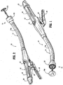
- anvil assembly 100 is shown operably connected to a system for delivering anvil assembly 100 within a patient "P" ( FIG. 25 ) shown generally as anvil delivery system 200.
- Anvil delivery system 200 includes a tubular guide assembly 202 and a suture guide assembly 204.
- Each of tubular and suture guide assemblies 202, 204 are selectively secured to anvil assembly 100 to facilitate trans-oral positioning of anvil assembly 100 within a patient.
- tubular guide assembly 202 is configured to be manually detached from anvil assembly 100 prior to attachment of anvil assembly 100 to stapling device 10 ( FIG. 1 ) and suture guide assembly 204 is configured to be automatically detached from anvil assembly 100 following the stapling stroke of the stapling device 10 ( FIG. 1 ).
- tubular guide assembly 202 includes a flexible tube 210 for trans-oral positioning of anvil assembly 100 within a patient "P" ( FIG. 20 ) and an adapter 220 for connecting flexible tube 210 to anvil assembly 100.
- Flexible tube 210 includes an open end 210a for supporting adapter 220 and a closed end 210b configured for trans-oral receipt in a patient.
- Open end 210a of flexible tube 210 defines a throughbore 211 configured to receive a locking pin 214.
- Open end 210a further includes an opening 213.
- Flexible tube 210 may include markings or other gradations 216 ( FIG. 11 ) along the length thereof to indicate to a surgeon the depth of insertion of the flexible tube 210 within the patient during tran-oral positioning of anvil assembly 100 within a patient and/or to indicate the length of flexible tube 210 remaining in the patient during removal.
- Adapter 220 includes a first end 220a configured to be received within open end 210a of flexible tube 210 and a second end 220b configured to be received within bore 161 formed in center rod 160 of anvil assembly 100.
- a first end 220a of adapter 220 includes a series of annular rings 222 configured to frictionally retain first end 220a of adapter 220 within open end 210a of flexible tube 210.
- a second end 220b of adapter 220 includes a longitudinal guide member 224 configured to be received between two adjacent flexible arms 164 of center rod 160 of anvil assembly 100. Second end 220b of adapter 220 is sized to allow center rod 160 of anvil assembly 100 to freely slide onto and off of second end 220b of adapter 220.
- Adapter 220 further defines a first throughbore 221 formed in a central hub portion 226 as well as second and third throughbores 223, 225 formed in first end 220a.
- Throughbore 225 is configured to align with throughbore 211 formed in open end 210a of flexible tube 210 and is sized to receive locking pin 214.
- Throughbore 223 is configured to receive both ends of the first suture "S 1 .”
- Throughbore 221 can also receive the suture ends to enhance retention.
- first suture "S 1 " is threaded through openings 117a formed on anvil head 110 such that first and second ends of first suture “S 1 " are positioned on different sides of center rod 160.
- Second end 220b of adapter 220 is positioned within throughbore 161 of center rod 160 such that longitudinal guide 224 ( FIG. 10 ) of adapter 220 is received between two arm members 164 ( FIG. 7 ) of center rod 160.
- Each of the first and second ends of first suture "S 1 " is then inserted through throughbore 223 formed in adapter 220.
- Anvil head 110 is then rotated to a first tilted position against the bias of spring 196 and the first and second ends of first suture "S 1 " are pulled through opening 223 to apply tension on anvil head 110 to retain anvil head 110 in the first tilted position as shown in FIG. 12 .
- first end 220a of adapter 220 is inserted into open end 210a of flexible member 210.
- the frictional contact between annular rings 222 of first end 220a of adapter 220 and an inner surface of flexible tube 210 secures adapter 220 to flexible tube 210 and prevents first suture "S 1 " from loosening as it is clinched between the outer wall of the adapter 220 and inner wall of flexible tube 210.
- more than one suture may be used to secure anvil head assembly 110 in a pre-fired tilted position.
- first suture "S 1 " need not be passed through bore 221 but instead can clamped between adapter 220 and the inner wall of the flexible tube 210.
- suture guide assembly 204 of anvil delivery system 200 includes a reel assembly 230.
- Reel assembly 230 is configured to house and facilitate manipulation of second suture "S 2 ".
- Reel assembly 230 includes a housing 240 and a reel member 250.
- housing 240 of reel assembly 230 includes a substantially circular body 242 defining an annular cavity or recess 241.
- Circular body 242 may include a textured surface to facilitate operable engagement by a user, e.g. ribs 242a ( FIG. 13 ).
- Housing 240 further includes a radially outward extending tab 244 and an annular flange 246.
- Tab 244 defines an opening 243 and a pair of slots 245. Opening 243 is configured to receive second suture "S 2 " and operates to guide second suture "S 2 " from reel member 250 ( FIG. 15 ).
- Slots 245 are configured to selectively receive and secure second suture "S 2 " once a sufficient length of second suture "S 2 " is released from reel member 250.
- reel member 250 of reel assembly 230 includes a substantially circular body 252 defining an annular recesses 251 extending about an outer perimeter 254 of circular body 252.
- Annular recess 253 is configured to receive second suture "S 2 ".
- Circular body 252 further defines an opening 253 configured to operably receive annular flange 246 of housing 240 such that circular body 252 is rotatably supported within annular cavity 241 of a housing 240.
- Circular body 252 is rotatably supported within housing 240 to permit the release of second suture "S 2 " from within annular recess 251 of reel member 250.
- suture guide assembly 204 of anvil delivery system 200 is shown operably attached to anvil assembly 100.
- suture guide assembly 204 may be provided to a clinician pre-attached to anvil assembly 100, is envisioned that suture guide assembly 204 and anvil assembly 100 may be provided as separate components that can be attached to one another by a clinician prior to use.
- Second suture "S 2 " is attached to anvil assembly 100 by threading an end of second suture "S 2 " into a first opening of second openings 117b of anvil head 110, through slot 133 of cutting ring 130 and notch 116a of anvil head 110, and out a second opening of second openings 117b.
- Second suture “S 2 " First and second ends of second suture “S 2 " are then threaded through opening 243 formed in tab 244 of housing 240 of reel assembly 230 and secured about reel member 250 of reel assembly 230.
- second suture "S 2 " is wound in annular recess 251 about reel member 250.
- Reel member 250 is then secured to housing 240 by positioning reel member 250 within annular cavity 241 of housing 240 and positioning flange 246 of housing 240 within opening 253 of reel member 250.
- anvil assembly 100 is provided in the first tilted position supported on tubular guide member 202 of anvil delivery system 200 and suture guide assembly 204 is attached to anvil head 110 such that anvil assembly 100 is ready for delivery.
- the suture guide assembly 204 and tubular guide assembly 202 can be provided separately from anvil assembly 100 and a clinician can secure anvil assembly 100 to tubular guide assembly 202 and/or suture guide assembly 204 of anvil delivery system 200 as discussed above.
- tubular guide assembly 202, suture guide assembly 204, and/or anvil assembly 100 may be provided to a clinician as separate components, or together as kit.
- Suture guide assembly 204 may be used at any point during insertion and prior to completion of the stapling procedure to retract anvil assembly 100 back through esophagus "E” and out of the patients mouth "M”. Suture guide assembly 204 may also be used to manipulate anvil assembly 100 in the event anvil assembly 100 becomes stuck and/or, is not properly positioned within the patient "P”.
- a second incision "I 2 " is then formed at the surgical site such that distal head portion 16 of stapling device 10 may be received therethrough.
- distal head portion 16 of stapling device 10 may be received through first incision "I 1 " once tubular guide assembly 202 of anvil deliver system 200 has been removed therefrom.
- anvil assembly 100 can be secured to stapling device 10 by inserting retractable trocar 54 into bore 161 of center rod 160 of anvil assembly 100. Because the anvil retainer assembly 50 is unapproximated when anvil assembly 100 is attached and stapling device 10 ( FIG. 1 ) has yet to be fired, trocar 54 is in its advanced position.
- trocar 54 When trocar 54, in its advanced position, is inserted into center rod throughbore 161, tip 54b of trocar 52 engages base portion 182 of second slide member 180 and moves second slide member 180 towards first slide member 170 to move anvil head 110 from its tilted position to its operative, non-tilted position via links 190, 192 with anvil head 110 in its operative position, tissue to anastomosed can be secured about anvil center rod 160 using known techniques.
- cam member 62 is prevented from pivoting by bushing 44 and arms 43 of pusher 40. Since cam member 62 is not free to pivot, finger 62a is positioned to prevent pin 58 from moving proximally within body portion 52 of anvil retainer assembly 50 to prevent retraction of trocar 54. As such, trocar tip 54b engages second slide member 180 to retain second slide member 180 in its advanced position. As such, anvil head 102 is retained in the operative, non-tilted position.
- stapling device 10 ( FIG. 1 ) may then be fired.
- knife blade 38 mounted within shell assembly 30 on distal end portion 16 of stapling device 10 is advanced distally into engagement with head assembly 102 of anvil assembly 100.
- knife blade 38 can be advanced subsequent to and/or independently of pusher 40.
- Distal advancement of knife blade 38 causes knife blade 38 to pass through cover 140 and into cutting ring 130 of anvil assembly 100.
- second suture "S 2 " which is received within slot 133 of cutting ring 130 is severed.
- second suture "S 2 " and suture guide assembly 204 is disconnected from anvil assembly 100.
- suture guide assembly 204 may be used to facilitate position of anvil assembly 100 and/or to retract anvil assembly 100 back through the patient's mouth "M” ( FIG. 20 ).
- second suture “S 2” does not need to be retracted through second openings 117b ( FIG. 19 ) to detach second suture “S 2 " from anvil assembly 100. This reduces the likelihood of any tissue damage caused by friction while retracting second suture "S 2 " from head assembly 102.
- the likelihood of introducing bacteria or other foreign material into the patient is reduced.
- anvil head 110 Because of the proximity of anvil head 110 to shell assembly 30, anvil head 110 will only move to its tilted reduced profile position during unapproximation of anvil assembly 100 and shell assembly 30. Anvil assembly 100 may then be removed from the surgical site and the surgical procedure may be completed in a traditional manner.
- the suture can be attached to the anvil assembly at a location that is not near the knife or cut ring. In this way, the knife does not sever the suture.
- the procedure is carried out as discussed above, except that one leg only of the suture is cut and then the suture guide assembly and suture are removed.
- the anvil assembly is attached to the instrument, attachment actuating the movement of the anvil away from the tilted position, and the instrument is fired. Firing initiates movement of the anvil from the operative position back to the tilted position.
Description
- The present disclosure relates to an anvil delivery system for use with a surgical stapling device for trans-oral delivery of an anvil assembly.
- Anastomosis is the surgical joining of separate hollow organ sections to allow the sections to communicate with each other. Typically, an anastomosis procedure follows surgery in which a diseased or defective section of hollow tissue is removed and the remaining end sections are to be joined. Depending on the desired anastomosis procedure, the end sections of the hollow organ may be joined using circular, end-to-end, end-to-side, or side-to-side organ reconstruction methods.
- In a circular anastomosis procedure, the two ends of the organ sections are joined by means of a surgical stapling instrument which drives a circular array of staples through the organ end sections and cores and removes any overlapping tissue to free a tubular passage. In some applications of a circular anastomosis procedure, an anvil rod having an attached anvil head is mounted to the distal end of a surgical stapling instrument shaft prior to insertion of the instrument into the tissue to be anastomosed. However, in other applications, a detachable anvil rod may be mounted to the instrument subsequent to positioning of the surgical stapling instrument and the anvil assembly within respective tissue sections. In such instances, the surgical stapling instrument and the anvil assembly are separately delivered to the operative site. Each tissue end section is then secured to a respective anvil or staple holding component, e.g., by a purse string suture. The anvil assembly is mounted to the surgical stapling instrument by inserting a mounting portion of the anvil rod within the distal end of the surgical stapling instrument so that a mounting mechanism within the surgical stapling instrument securely engages the anvil rod. Preparation of the tissue sections to be joined and mounting of the anvil rod to the surgical stapling instrument may be performed using minimally invasive surgical techniques, i.e., under laparoscopic guidance.
- An anvil assembly delivery system for delivering an anvil assembly trans-orally to a surgical site, e.g., the stomach, is disclosed in commonly owned
U.S. Patent No. 8,109,426 . As described, a guide suture is threaded through openings in the head of the anvil assembly to facilitate trans-oral insertion of the anvil assembly and to allow retrieval of the anvil assembly prior to attachment of the anvil assembly to the surgical stapling instrument. At any point during the stapling procedure, the guide suture may be detached from the anvil assembly by pulling the guide suture back through the openings in the anvil head. - To prevent premature detachment of the guide suture from the anvil assembly during trans-oral insertion, it would be beneficial to have an anvil assembly that is configured such that the guide suture remains attached to the anvil assembly until the stapling procedure is complete, i.e., after the tissue to be anastomosed has been stapled and cut.
- The present invention is defined in independent claim 1 and certain optional features thereof are defined in the dependent claims.
- In accordance with the present disclosure, an anvil assembly is provided for use with a surgical stapling instrument for performing end-to-end anastomosis of tissue. The anvil assembly includes an anvil center rod, and a head assembly pivotally secured to the anvil center rod about a pivot axis and movable between an operative position and a tilted position. The head assembly includes an anvil head and a cutting ring disposed within the anvil head. The anvil head defines first and second openings and the cutting ring defines a slot in alignment with the first and second openings.
- In one embodiment, the first and second openings and the slot are dimensioned to receive a suture. The anvil center rod may include first and second slide members. The first slide member may be pivotally connected to the head assembly on one side of the pivot axis by a first drive link and the second slide member being connected to the head assembly on the other side of the pivot axis by a second drive link. The first slide member may be movable in relation to the second slide member to effect movement of the head assembly between the operative position and the tilted position. The anvil assembly may further include a biasing member positioned to urge the first slide member in relation to the second slide member to position the head assembly in the tilted position. The biasing member may be positioned between the first slide member and the second slide member to urge the first and second slide members apart.
- In accordance with the present disclosure there is also provided an anvil delivery system including an anvil assembly and a suture guide assembly. The suture guide assembly includes a guide suture secured to the head assembly and a reel assembly configured for selectively dispensing the guide suture. The guide suture may be received through the first opening in the anvil head, passes through the slot in the cutting ring, and extends from the second opening in the anvil head. The reel assembly may include a housing and a reel member rotatably received within the housing. The guide suture may be supported about the reel member. The reel member may define an annular channel for receiving the guide suture. The housing may define an annular cavity. The reel member may be rotatably supported on the housing within the annular cavity.
- In some embodiments, the anvil delivery system may further include a tubular guide assembly for trans-oral insertion of the anvil assembly. The tubular guide assembly may include a flexible tube and an adapter configured for operably connecting the flexible tube to the anvil center rod. The tubular guide assembly may further include a retaining suture for retaining the head assembly of the anvil assembly in the tilted position. The retaining suture may be received through third and fourth openings in the anvil head and may be secured between the adapter and the flexible tube.
- Embodiments of the presently disclosed anvil delivery system are described hereinbelow with reference to the drawings wherein:
-
FIG. 1 is a top side perspective view from the proximal end of the presently disclosed surgical stapling device in the unapproximated position; -
FIG. 2 is a top side perspective view from the distal end of the surgical stapling device shown inFIG. 1 ; -
FIG. 3 is a side cross-sectional view of the distal end of the central body portion and distal head portion of the surgical stapling device shown inFIGS. 1 and 2 , with the anvil assembly removed; -
FIG. 4 is a side exploded perspective view of the distal head portion, anvil retainer assembly and pusher back of the surgical stapling device shown inFIGS. 1 and 2 ; -
FIG. 5 is a perspective view from the proximal end of the anvil assembly of the surgical stapling device shown inFIGS. 1 and 2 , with the anvil head in a tilted reduced profile position; -
FIG. 6 is a perspective view of the anvil assembly shown inFIG. 5 with the anvil head in the tilted reduced profile position and the anvil plate and cover removed; -
FIG. 7 is an exploded side perspective view of the anvil assembly shown inFIG. 5 ; -
FIG. 8 is a side view of an anvil delivery system, including a tubular guide assembly and a suture guide assembly, attached to the anvil assembly shown inFIG. 5 , with the anvil head positioned in the tilted reduced profile position; -
FIG. 9 is an enlarged view of the indicated area of detail shown inFIG. 8 ; -
FIG. 10 is an enlarged perspective view of a tubular member and an adapter of the tubular guide assembly shown inFIG. 8 ; -
FIG. 11 is an side view of the anvil delivery system shown inFIG. 8 , including the anvil assembly shown inFIGS. 5-7 shown in the first tilted position and a first suture; -
FIG. 12 is a side cross-sectional view taken along section line 12-12 ofFIG. 11 ; -
FIG. 13 is a top view of a housing of the suture reel of the suture guide assembly shown inFIG. 8 ; -
FIG. 14 is a side cross-sectional view of the housing shown inFIG. 14 ; -
FIG. 15 is a top view of a reel member of the reel assembly of the suture guide assembly shown inFIG. 8 ; -
FIG. 16 is a side cross-sectional view of the reel member shown inFIG. 15 ; -
FIG. 17 is a perspective view of the suture guide assembly of the anvil delivery system shown inFIG. 8 attached to the anvil assembly shown inFIG. 5 ; -
FIG. 18 is a cross-sectional view taken along section line 18-18 ofFIG. 17 ; -
FIG. 19 is an enlarged view of indicated area of detail shown inFIG. 18 ; -
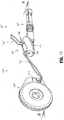
FIG. 20 is an illustration of the surgical stapling device shown inFIGS. 1 and 2 inserted into a stomach of a patient and the anvil delivery system with the connected anvil assembly shown inFIG. 8 being inserted trans-orally into a patient; -
FIG. 21 is side cross-sectional view of the distal end of the central body portion and distal head portion of the surgical stapling device and the anvil assembly shown inFIG. 1 with the anvil assembly in its unapproximated position and the anvil head in the operative position; -
FIG. 22 is a cross-sectional view of the distal end of the central body portion and distal head portion shown inFIG. 21 ninety-degrees offset from the cross-sectional view ofFIG. 21 ; -
FIG. 23 is a cross-sectional view of the distal end of the central body portion and distal head portion shown inFIG. 21 with the anvil head in the approximated position; -
FIG. 24 is a cross-sectional view of the distal end of the central body portion and distal head portion shown inFIG. 22 ninety-degrees offset from the cross-sectional view ofFIG. 23 with the anvil head in the approximated position; -
FIG. 25 is a cross-sectional side view of the anvil assembly shown inFIG. 24 with the distal end portion of the surgical stapling device including a knife blade shown in phantom during firing of the stapling device; -
FIG. 26 is a cross-sectional view of the distal end of the central body portion and distal head portion shown inFIG. 23 with the anvil head in the approximated position after the stapling device has been fired; -
FIG. 27 is a cross-sectional view of the distal end of the central body portion and distal head portion shown inFIG. 24 offset ninety degrees from the cross-sectional view ofFIG. 26 after the stapling device has been fired; and -
FIG. 28 is a cross-sectional view of the distal end of the central body portion and distal head portion shown inFIG. 27 after the anvil head has been unapproximated and pivoted to the tilted position. - Embodiments of the presently disclosed anvil delivery system will now be described in detail with reference to the drawings in which like reference numerals designate identical or corresponding elements in each of the several views. As is common in the art, the term "proximal" refers to that part or component closer to the user or operator, i.e. surgeon or clinician, while the term "distal" refers to that part or component further away from the user.
- Referring to
FIGS. 1 and 2 , a surgical stapling instrument including an anvil assembly according to the present disclosure is shown generally as staplingdevice 10. Briefly, staplingdevice 10 includes aproximal handle assembly 12, an elongatedcentral body portion 14 including a curved elongatedouter tube 14a, and adistal head portion 16. Handleassembly 12 includes astationary handle 18, a firingtrigger 20, arotatable approximation knob 22, and anindicator 24. A pivotally mountedtrigger lock 26 is fastened to handleassembly 12 and is manually positioned to prevent inadvertent firing of staplingdevice 10.Indicator 24 is positioned on thestationary handle 18 and includes indicia, e.g., color coding, alpha-numeric labeling, etc., to identify to a surgeon whether the device is approximated and is ready to be fired.Head portion 16 includes ananvil assembly 100 and ashell assembly 30. The structure and function of staplingdevice 10 will only be described to the extent necessary to fully disclose the operation ofanvil assembly 100. For a more detailed description of an exemplary stapling device, please refer to commonly ownedU.S. Patent No. 7,364,060 , ("the '060 patent"). - Although a manual handle assembly is described, the surgical stapling device may be a powered (e.g., motor operated) surgical instrument, or part of a robotic surgical system, in any of the embodiments disclosed herein.
- With reference now to
FIGS. 3 and4 ,distal end portion 16 of staplingdevice 10 includesshell assembly 30 which is secured to a distal end of thecentral body portion 14, apusher 40 extending distally throughcentral body portion 14, and ananvil retainer assembly 50 extending throughpusher 40 andshell assembly 30. Although not shown,anvil retainer assembly 50 is operably connected to an approximation mechanism of staplingdevice 10 which is actuated by the rotatable approximation knob 22 (FIG. 1 ), andpusher 40 is operably connected to a firing mechanism of staplingdevice 10 which is actuated by the firing trigger 20 (FIG. 1 ). For a more detailed description of the approximation mechanism and/or the firing mechanism of the staplingdevice 10, see the '060 patent. -
Shell assembly 30 includes a shell orhousing 32, a pusher back 34, astaple guide 36, a cylindrical knife 38 (FIG. 25 ), and a plurality of staples "S".Shell 32 includes anouter housing portion 32a and an inner housing portion 32b (FIG. 3 ).Staple guide 36 is supported in the distal end ofouter housing portion 32a and includes an annular array ofstaple receiving pockets 36a for housing staples "S". Pusher back 34 is slidably supported inshell 32 betweenouter housing portion 32a and inner housing portion 32b and includes a plurality offingers 34a which are each slidably received in respectivestaple pockets 36a instaple guide 36. Pusher back 34 includes a pair ofrecesses 35 which receivedetents 42a formed onflexible fingers 42 of apusher 40 to securepusher 40 to pusher back 34 such that pusher back 34 is movable withpusher 40 from a retracted position to an advanced position to eject staples "S" fromstaple guide 36. - In any of the embodiments disclosed herein, the shell assembly may be configured as a removable and replaceable assembly. In this way, after the staples are fired, the shell assembly can be replaced, providing a new set of staples, even staples of a different size or configuration, and a fresh knife.
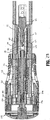
- An elongated
hollow bushing 44 is fixedly retained in inner housing portion 32b ofshell 32 using, e.g., screw threads, a friction fitting, or the like.Bushing 44 defines a channel 45 through whichanvil retainer assembly 50 andanvil center rod 160 reciprocate during approximation and separation ofanvil assembly 100 andshell assembly 30.Bushing 44 provides additional strength to inner housing portion 32b ofshell 32 to prevent separation of theanvil assembly 100 andanvil retainer assembly 50 during firing of the staplingdevice 10. -
Anvil retainer assembly 50 includes a two-part assembly having abody portion 52 defining alongitudinal throughbore 53 and a trocar or lockingmember 54 slidably received withinlongitudinal throughbore 53.Longitudinal throughbore 53 includes a stepped portion orshoulder 53a (FIG. 3 ). -
Trocar 54 includes an annular flange or shoulder 54a on a proximal end and a blunt tip 54b on a distal end. Tip 54b oftrocar 54 extends from the distal end ofbody portion 52 ofanvil retainer assembly 50 and is movable withinthroughbore 53 ofbody portion 52 from an advanced position to a retracted position. A biasing member, e.g., acoil spring 56, is positioned between annular flange 54a andshoulder 53a of longitudinal bore 53 (FIG. 3 ). The biasingmember 56 urges trocar 54 to its retracted position. The proximal end oftrocar 54 includes atransverse slot 55 having a pin orrod 58 extending therethrough.Pin 58 is slidably positioned withinlongitudinal slots 55 formed inbody portion 52. The distal and proximal ends ofslots 55 define the advanced and retracted positions oftrocar 54, respectively. -
Body portion 52 ofanvil retainer assembly 50 includes anannular protrusion 60 and defines a longitudinal slot 61.Annular protrusion 60 facilitates attachment ofanvil assembly 100 toanvil retainer assembly 50 as will be discussed in further detail below. Acam member 62 is pivotally supported about apivot member 64 in slot 61 at a position proximal ofpin 58.Cam member 62 includes a distal finger 62a having an angled face and arecess 63 positioned proximally of finger 62a for receivingpin 58 oftrocar 54.Pin 58 is urged bycoil spring 56 towards finger 62a. Engagement between the angled face of finger 62a andpin 58 urgescam member 62 to pivot aboutpivot member 64 to allowpin 58 to move intorecess 63. - Referring now to
FIGS. 5-7 ,anvil assembly 100 is configured for releasable attachment to stapling device 10 (FIG. 1 ).Anvil assembly 100 includes ahead assembly 102 and arod assembly 104.Head assembly 102 is pivotally secured torod assembly 104 and is configured to selectively move between a tilted position (FIG. 5 ) and an operative position (FIG. 21 ). - With particular reference to
FIG. 7 ,head assembly 102 includes ananvil head 110, ananvil post 120, acutting ring 130, acover 140, and ananvil plate 150.Rod assembly 104 includes ananvil center rod 160, afirst slide member 170, asecond slide member 180, first andsecond link members second slide members rod assembly 104 withanvil post 120 ofhead assembly 102, and aspring member 196 for biasing first andsecond slide members - With reference still to
FIGS. 5-7 ,anvil head 110 ofhead assembly 102 defines a centrally located throughbore 111 configured to receiveanvil post 120, an innerannular recess 113 configured to receivecut ring 130, and an outerannular recess 115 configured to receiveanvil plate 150. Innerannular recess 113 and outerannular recess 115 are separated by anannular flange 116 defining a notch 116a.Anvil head 102 further defines a first set of openings 117a configured to receive a first or retaining suture "S1" and a second set of openings 117b configured to receive a second or guide suture "S2". As will be described in further detail below, first suture "S1" is a component oftubular guide assembly 202 ofanvil delivery system 200 and second suture "S2" is a component ofsuture guide assembly 204 ofanvil delivery system 200. -
Anvil post 120 is configured to be secured within throughbore 111 ofanvil head 110.Anvil post 120 defines lateral slot 121 configured to accommodate first andsecond link members transverse bore 123 extending across longitudinal slot 121 for receiving apivot member 106, and a pair of smalltransverse bores 115a, 115b extending across longitudinal slot 121 for receiving pivot pins 106a, 108a, respectively.Pivot member 106 pivotally connectsanvil post 120 to adistal end 160b ofcenter rod 160 via a cooperatingbore 163 formed incenter rod 160. In one embodiment,pivot member 106 includes a pin or post which defines a transverse axis which is spaced laterally from the longitudinal axis "x" defined bycenter rod 160 such thatanvil head 110 can pivot approximately ninety degrees (90°) from an operative position (FIG. 21 ) in which a plane defined bytissue contacting surface 152 ofanvil plate 150 ofhead assembly 102 is substantially perpendicular to the longitudinal axis "x" ofcenter rod 160 to a tilted reduced profile position (FIG. 28 ) in whichhead assembly 110 is substantially parallel to longitudinal axis "x" ofcenter rod 160. Alternately, other types of pivot members at a variety of locations in relation to longitudinal axis "x" ofcenter rod 160 may be incorporated intoanvil assembly 100. Pivot pins 106a, 108a pivotally connect first andsecond links rod assembly 104 withanvil post 120. - Referring also to
FIGS. 5 and7 , cuttingring 130 defines athroughbore 131 configured to be positioned aboutanvil post 120 and has aradial slot 133 configured to align with second set of openings 117b inanvil head 110. When cuttingring 130 is received within innerannular recess 113 ofanvil head 110,radial slot 133 is configured to accommodate second suture "S2" ofsuture guide assembly 204 ofanvil delivery system 200 which is received through the second set of openings 117b. Cover 140 defines athroughbore 141 and is configured to be received between cuttingring 130 andanvil plate 150. Cover 140 may be formed of Mylar® or other protective material. -
Anvil plate 150 includes atissue contacting surface 152 defining a plurality staple forming recesses 153.Anvil plate 150 further includes atab 154 configured to be received within aslot 115a formed inanvil head 110.Tab 154 andslot 115a cooperate to positionanvil plate 150 in the proper orientation withinouter recess 115 ofanvil head 110. - Referring to
FIGS. 5-7 ,center rod 160 ofrod assembly 104 includes proximal anddistal ends 160a, 160b and defines athroughbore 161. As shown, proximal end 160a includes at least oneopening 165 configured to receive a suture or the like to facilitate positioning ofanvil assembly 100 within a hollow organ. A distal end of throughbore 161 (seeFIG. 18 ) is configured to slidably receive at least a portion of each of first andsecond slide members - With particular reference to
FIG. 7 ,first slide member 170 ofrod assembly 104 includes a substantially annular body having an open proximal end 170a and a closeddistal end 170b and defining athroughbore 171 extending between proximal anddistal ends 170a, 170b.Throughbore 171 is configured to accommodatespring member 196.First slide member 170 further defines a longitudinal cut-away 173 which extends between proximal anddistal ends 170a, 170b and is in communication withthroughbore 173.Cutaway 173 is configured to accommodatesecond slide member 180 such that first andsecond slide members Distal end 170b offirst slide member 170 includes a radially outward extendingflange 172 defining a transverse bore 175 configured to receive pivot pin 106b. Pivot pin 106b secures a first end 190a offirst link 190 ofrod assembly 104 to thefirst slide member 170. A second end 190b offirst link 190 is secured withanvil post 120 ofhead assembly 102 by a pivot pin 106a.Distal end 170b further includes anub 174 extending proximally withinthroughbore 171 configured to support and align a distal end 196b ofspring member 196 withinthroughbore 171. -
Second slide member 180 ofrod assembly 104 is configured for longitudinal movement relative tofirst slide member 170.Second slide member 180 includes a longitudinal body having a closed proximal end 180a, an open distal end 180b, and is configured to be received in the cut-away 173 offirst slide member 170. As noted above, this configuration permits sliding offirst slide member 170 in relation tosecond slide member 180. A radially outward extendingflange 182 extends along a majority of the length ofsecond slide member 180 and defines atransverse bore 185 configured to receive pivot pin 108b for securingsecond link 192 ofrod assembly 104 withanvil post 120 ofhead assembly 102. A proximal end 180a ofsecond slide member 180 includes adistally extending nub 184 which supports and aligns a proximal end 196a ofspring member 196 withinthroughbore 171. - A spring or biasing member, e.g.,
coil spring 196, is positioned between first andsecond slide members link 192 is pivotally connected at a proximal end 192a tosecond slide member 180 by pivot pin 108b and is pivotally connected at a distal end 192b toanvil post 120 by pivot pin 108a. First andsecond links members anvil post 120 in such a manner that when biasingmember 196 urges first andsecond slide members anvil head 110 pivots aboutpivot member 106 to its tilted reduced profile position (FIG. 28 ). -
Center rod 160 includes a plurality offlexible arms 164 which defines a proximal end ofthroughbore 161 and is configured to releasably engage a removable trocar, adaptor and/or theannular protrusion 60 of thebody portion 52 of theanvil retainer assembly 50. A plurality ofsplines 166 are formed aboutcenter rod 160.Splines 166 mesh with grooves (not shown) formed in stapling device 10 (FIG. 1 ) to properly alignanvil assembly 100 in relation to shell assembly 30 (FIG. 3 ) of staplingdevice 10 during approximation ofanvil assembly 100 andshell assembly 30. - In any of the embodiments disclosed herein, the pivoting anvil assembly, which includes a head assembly and a rod assembly, may be arranged differently. For example, see the tilting anvil assembly disclosed in
U.S. Patent Application No. 13/915,953 . - With reference now to
FIGS. 8 and 9 ,anvil assembly 100 is shown operably connected to a system for deliveringanvil assembly 100 within a patient "P" (FIG. 25 ) shown generally asanvil delivery system 200.Anvil delivery system 200 includes atubular guide assembly 202 and asuture guide assembly 204. Each of tubular andsuture guide assemblies anvil assembly 100 to facilitate trans-oral positioning ofanvil assembly 100 within a patient. As will be described in further detail below,tubular guide assembly 202 is configured to be manually detached fromanvil assembly 100 prior to attachment ofanvil assembly 100 to stapling device 10 (FIG. 1 ) andsuture guide assembly 204 is configured to be automatically detached fromanvil assembly 100 following the stapling stroke of the stapling device 10 (FIG. 1 ). - With reference now to
FIGS. 8-12 ,tubular guide assembly 202 includes aflexible tube 210 for trans-oral positioning ofanvil assembly 100 within a patient "P" (FIG. 20 ) and anadapter 220 for connectingflexible tube 210 toanvil assembly 100.Flexible tube 210 includes anopen end 210a for supportingadapter 220 and aclosed end 210b configured for trans-oral receipt in a patient.Open end 210a offlexible tube 210 defines athroughbore 211 configured to receive alocking pin 214.Open end 210a further includes anopening 213.Flexible tube 210 may include markings or other gradations 216 (FIG. 11 ) along the length thereof to indicate to a surgeon the depth of insertion of theflexible tube 210 within the patient during tran-oral positioning ofanvil assembly 100 within a patient and/or to indicate the length offlexible tube 210 remaining in the patient during removal. -
Adapter 220 includes a first end 220a configured to be received withinopen end 210a offlexible tube 210 and a second end 220b configured to be received withinbore 161 formed incenter rod 160 ofanvil assembly 100. A first end 220a ofadapter 220 includes a series ofannular rings 222 configured to frictionally retain first end 220a ofadapter 220 withinopen end 210a offlexible tube 210. A second end 220b ofadapter 220 includes alongitudinal guide member 224 configured to be received between two adjacentflexible arms 164 ofcenter rod 160 ofanvil assembly 100. Second end 220b ofadapter 220 is sized to allowcenter rod 160 ofanvil assembly 100 to freely slide onto and off of second end 220b ofadapter 220.Adapter 220 further defines afirst throughbore 221 formed in acentral hub portion 226 as well as second andthird throughbores 223, 225 formed in first end 220a.Throughbore 225 is configured to align withthroughbore 211 formed inopen end 210a offlexible tube 210 and is sized to receive lockingpin 214. Throughbore 223 is configured to receive both ends of the first suture "S1."Throughbore 221 can also receive the suture ends to enhance retention. For a more detailed description of an exemplary tubular guide assembly including a flexible tube and an adapter, please refer to commonly ownedU.S. Patent No. 8,109,426 . - In order to secure
anvil assembly 100 ontubular guide assembly 202 ofanvil delivery system 200, first suture "S1" is threaded through openings 117a formed onanvil head 110 such that first and second ends of first suture "S1" are positioned on different sides ofcenter rod 160. Second end 220b ofadapter 220 is positioned withinthroughbore 161 ofcenter rod 160 such that longitudinal guide 224 (FIG. 10 ) ofadapter 220 is received between two arm members 164 (FIG. 7 ) ofcenter rod 160. Each of the first and second ends of first suture "S1" is then inserted through throughbore 223 formed inadapter 220.Anvil head 110 is then rotated to a first tilted position against the bias ofspring 196 and the first and second ends of first suture "S1" are pulled through opening 223 to apply tension onanvil head 110 to retainanvil head 110 in the first tilted position as shown inFIG. 12 . - After first suture "S1" is tensioned to retain
anvil head 110 in the first tilted position, first end 220a ofadapter 220 is inserted intoopen end 210a offlexible member 210. The frictional contact betweenannular rings 222 of first end 220a ofadapter 220 and an inner surface offlexible tube 210 securesadapter 220 toflexible tube 210 and prevents first suture "S1" from loosening as it is clinched between the outer wall of theadapter 220 and inner wall offlexible tube 210. It is envisioned that more than one suture may be used to secureanvil head assembly 110 in a pre-fired tilted position. It is also envisioned that first suture "S1" need not be passed throughbore 221 but instead can clamped betweenadapter 220 and the inner wall of theflexible tube 210. - Turning back to
FIG. 9 ,suture guide assembly 204 ofanvil delivery system 200 includes areel assembly 230.Reel assembly 230 is configured to house and facilitate manipulation of second suture "S2".Reel assembly 230 includes ahousing 240 and areel member 250. - With reference now to
FIGS. 13 and 14 ,housing 240 ofreel assembly 230 includes a substantiallycircular body 242 defining an annular cavity orrecess 241.Circular body 242 may include a textured surface to facilitate operable engagement by a user, e.g. ribs 242a (FIG. 13 ).Housing 240 further includes a radially outward extendingtab 244 and anannular flange 246.Tab 244 defines anopening 243 and a pair ofslots 245.Opening 243 is configured to receive second suture "S2" and operates to guide second suture "S2" from reel member 250 (FIG. 15 ).Slots 245 are configured to selectively receive and secure second suture "S2" once a sufficient length of second suture "S2" is released fromreel member 250. - Turning to
FIGS. 15 and 16 ,reel member 250 ofreel assembly 230 includes a substantiallycircular body 252 defining anannular recesses 251 extending about anouter perimeter 254 ofcircular body 252.Annular recess 253 is configured to receive second suture "S2".Circular body 252 further defines anopening 253 configured to operably receiveannular flange 246 ofhousing 240 such thatcircular body 252 is rotatably supported withinannular cavity 241 of ahousing 240.Circular body 252 is rotatably supported withinhousing 240 to permit the release of second suture "S2" from withinannular recess 251 ofreel member 250. - Referring to
FIGS. 17-19 ,suture guide assembly 204 ofanvil delivery system 200 is shown operably attached toanvil assembly 100. Althoughsuture guide assembly 204 may be provided to a clinician pre-attached toanvil assembly 100, is envisioned thatsuture guide assembly 204 andanvil assembly 100 may be provided as separate components that can be attached to one another by a clinician prior to use. Second suture "S2" is attached toanvil assembly 100 by threading an end of second suture "S2" into a first opening of second openings 117b ofanvil head 110, throughslot 133 of cuttingring 130 and notch 116a ofanvil head 110, and out a second opening of second openings 117b. First and second ends of second suture "S2" are then threaded throughopening 243 formed intab 244 ofhousing 240 ofreel assembly 230 and secured aboutreel member 250 ofreel assembly 230. To secure second suture "S2" to reelmember 250, second suture "S2" is wound inannular recess 251 aboutreel member 250.Reel member 250 is then secured tohousing 240 by positioningreel member 250 withinannular cavity 241 ofhousing 240 andpositioning flange 246 ofhousing 240 within opening 253 ofreel member 250. - With reference now to
FIG. 20 , a method for deliveringanvil assembly 100 to a surgical site within a patient will be described. In one method,anvil assembly 100 is provided in the first tilted position supported ontubular guide member 202 ofanvil delivery system 200 andsuture guide assembly 204 is attached toanvil head 110 such thatanvil assembly 100 is ready for delivery. Alternatively, thesuture guide assembly 204 andtubular guide assembly 202 can be provided separately fromanvil assembly 100 and a clinician can secureanvil assembly 100 totubular guide assembly 202 and/orsuture guide assembly 204 ofanvil delivery system 200 as discussed above. In this manner,tubular guide assembly 202,suture guide assembly 204, and/oranvil assembly 100 may be provided to a clinician as separate components, or together as kit. Onceflexible tube 210 oftubular guide assembly 202 has been secured toanvil assembly 100 and second suture "S2" ofsuture guide assembly 204 has been attached toanvil assembly 100, the surgeon insertsclosed end 210b offlexible tube 210 in the patient's mouth "M" and movesclosed end 210b along withflexible tube 210 down through esophagus "E" to a surgical site, e.g., the stomach "St". Asanvil assembly 100 travels through esophagus "E" to the surgical site, second suture "S2" is unwound fromreel assembly 230 ofsuture guide assembly 204.Suture guide assembly 204 may be used at any point during insertion and prior to completion of the stapling procedure to retractanvil assembly 100 back through esophagus "E" and out of the patients mouth "M".Suture guide assembly 204 may also be used to manipulateanvil assembly 100 in theevent anvil assembly 100 becomes stuck and/or, is not properly positioned within the patient "P". - After insertion, the surgeon then makes a first incision "I1" at the surgical site (stomach "St" as shown) to provide access to
closed end 210b offlexible tube 210. Thereafter, the surgeon pullsopen end 210a offlexible tube 210 through first incision "I1" to position theanvil assembly 100 at the surgical site. In some procedures it may be beneficial to pullflexible tube 210 through incision "I1" untilcenter rod assembly 104 ofanvil assembly 100 advances through first incision "I1". Whenanvil assembly 100 is properly positioned at the surgical site, the surgeon releasestubular guide assembly 202 ofanvil delivery system 200 fromanvil assembly 100 by cutting suture "S1" and separatinganvil assembly 100 from second end 220b ofadapter 220.Flexible tube 210 andadapter 220 may then be pulled from the body through first incision "I1". Second suture "S2" ofsuture guide assembly 204 may also be secured withinslots 245 formed intab 244 ofhousing 240 ofreel assembly 230. - In one method, a second incision "I2" is then formed at the surgical site such that
distal head portion 16 of staplingdevice 10 may be received therethrough. Alternatively,distal head portion 16 of staplingdevice 10 may be received through first incision "I1" oncetubular guide assembly 202 of anvil deliversystem 200 has been removed therefrom. - Referring to
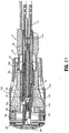
FIGS. 21 and22 , after staplingdevice 10 andanvil assembly 100 are positioned at the surgical site,anvil assembly 100 can be secured to staplingdevice 10 by insertingretractable trocar 54 intobore 161 ofcenter rod 160 ofanvil assembly 100. Because theanvil retainer assembly 50 is unapproximated whenanvil assembly 100 is attached and stapling device 10 (FIG. 1 ) has yet to be fired,trocar 54 is in its advanced position. Whentrocar 54, in its advanced position, is inserted into center rod throughbore 161, tip 54b oftrocar 52 engagesbase portion 182 ofsecond slide member 180 and movessecond slide member 180 towardsfirst slide member 170 to moveanvil head 110 from its tilted position to its operative, non-tilted position vialinks anvil head 110 in its operative position, tissue to anastomosed can be secured aboutanvil center rod 160 using known techniques. - Referring to
FIGS. 23 and24 , when theanvil assembly 100 andshell assembly 30 are approximated,cam member 62 is prevented from pivoting by bushing 44 andarms 43 ofpusher 40. Sincecam member 62 is not free to pivot, finger 62a is positioned to preventpin 58 from moving proximally withinbody portion 52 ofanvil retainer assembly 50 to prevent retraction oftrocar 54. As such, trocar tip 54b engagessecond slide member 180 to retainsecond slide member 180 in its advanced position. As such,anvil head 102 is retained in the operative, non-tilted position. - With reference now to
FIG. 25 , stapling device 10 (FIG. 1 ) may then be fired. During firing of staplingdevice 10,knife blade 38 mounted withinshell assembly 30 ondistal end portion 16 of staplingdevice 10 is advanced distally into engagement withhead assembly 102 ofanvil assembly 100. In some embodiments,knife blade 38 can be advanced subsequent to and/or independently ofpusher 40. Distal advancement ofknife blade 38causes knife blade 38 to pass throughcover 140 and into cuttingring 130 ofanvil assembly 100. Asknife blade 38 engages cuttingring 130, second suture "S2" which is received withinslot 133 of cuttingring 130 is severed. As such, second suture "S2" andsuture guide assembly 204 is disconnected fromanvil assembly 100. As noted above, prior to firing of stapling device 10 (FIG. 1 ),suture guide assembly 204 may be used to facilitate position ofanvil assembly 100 and/or to retractanvil assembly 100 back through the patient's mouth "M" (FIG. 20 ). By severing second suture "S2", second suture "S2" does not need to be retracted through second openings 117b (FIG. 19 ) to detach second suture "S2" fromanvil assembly 100. This reduces the likelihood of any tissue damage caused by friction while retracting second suture "S2" fromhead assembly 102. Further, by not having to retract second suture "S2" through second openings 117b inhead assembly 102 ofanvil assembly 100, the likelihood of introducing bacteria or other foreign material into the patient is reduced. - Referring to
FIGS. 26 and27 , when stapling device 10 (FIG. 1 ) is fired andpusher 40 is moved distally about bushing 44,arms 43 ofpusher 40 are deformed outwardly away fromcam member 62. Engagement betweenpin 58 and the angled face of finger 62a causescam member 62 to pivot. Whencam member 62 pivots, pin 58 moves proximally intorecess 63 ofcam member 62 andtrocar 54 moves to its retracted position withinlongitudinal bore 53 ofbody portion 52 under the bias ofspring 56. Astrocar 54 moves to its retracted position, biasingmember 196 urges first andsecond slide members anvil head 110 to its tilted reduced profile position (seeFIG. 28 ). Because of the proximity ofanvil head 110 to shellassembly 30,anvil head 110 will only move to its tilted reduced profile position during unapproximation ofanvil assembly 100 andshell assembly 30.Anvil assembly 100 may then be removed from the surgical site and the surgical procedure may be completed in a traditional manner. - In further embodiments, the suture can be attached to the anvil assembly at a location that is not near the knife or cut ring. In this way, the knife does not sever the suture. The procedure is carried out as discussed above, except that one leg only of the suture is cut and then the suture guide assembly and suture are removed. Then, the anvil assembly is attached to the instrument, attachment actuating the movement of the anvil away from the tilted position, and the instrument is fired. Firing initiates movement of the anvil from the operative position back to the tilted position.
- It will be understood that various modifications may be made to the embodiments disclosed herein. For example, the slotted cutting ring may be incorporated into anvil assemblies having alternative configurations. Therefore, the above description should not be construed as limiting, but merely as exemplifications of preferred embodiments. Those skilled in the art will envision other modifications within the scope of the claims appended hereto.
Claims (14)
- An anvil delivery system comprising:an anvil assembly (100) comprising:an anvil center rod (160); anda head assembly (102) pivotally secured to the anvil center rod (160) about a pivot axis and movable between an operative position and a tilted position, the head assembly (102) including an anvil head (110) and a cutting ring (130) disposed within the anvil head, the anvil head (110) defining first and second openings (117b); anda suture (S2) disposed in the first and second openings (117b);characterised in that:the cutting ring (130) defines a slot (133) in alignment with the first and second openings (117b) in the anvil head (110); andthe anvil delivery system comprises a suture guide assembly (204) including the suture (S2) and a reel assembly (230).
- The anvil delivery system of claim 1, wherein the first and second openings (117b) and the slot (133) are dimensioned to receive the suture (S2).
- The anvil delivery system of claim 1 or claim 2, further comprising an anvil tilting mechanism.
- The anvil delivery system of claim 3, wherein the anvil center rod (160) includes first and second slide members (170, 180), and wherein the anvil tilting mechanism comprises the first slide member (170) being pivotally connected to the head assembly (102) on one side of the pivot axis by a first drive link (190) and the second slide member (180) being connected to the head assembly (102) on the other side of the pivot axis by a second drive link (192), the first slide member (170) being movable in relation to the second slide member (180) to effect movement of the head assembly (102) between the operative position and the tilted position.
- The anvil delivery system of claim 4, further including a biasing member (196) positioned to urge the first slide member (170) in relation to the second slide member (180) to position the head assembly (102) in the tilted position.
- The anvil delivery system of claim 5, wherein the biasing member (196) is positioned between the first slide member (170) and the second slide member (180) to urge the first and second slide members (170, 180) apart.
- The anvil delivery system of any preceding claim, wherein the guide suture (S2) is received through the first opening (117b) in the anvil head (102), passes through the slot (133) in the cutting ring (130), and extends from the second opening (117b) in the anvil head (102).
- The anvil delivery system of any preceding claim, wherein the reel assembly (230) includes a housing (240) and a reel member (250) rotatably received within the housing (240), wherein the guide suture (S2) is supported about the reel member (250).
- The anvil delivery system of claim 8, wherein the reel member (250) defines an annular channel (251) for receiving the guide suture (S2).
- The anvil delivery system of claim 8 or claim 9, wherein the reel member (250) is rotatably supported on the housing (240) within an annular cavity (241) in the housing (240).
- The anvil delivery system of any preceding claim, further including a tubular guide assembly (202) for trans-oral insertion of the anvil assembly (100).
- The anvil delivery system of claim 11, wherein the tubular guide assembly (202) includes a flexible tube (210) and an adapter (220) configured for operably connecting the flexible tube (210) to the anvil center rod (160).
- The anvil delivery system of claim 12, wherein the tubular guide assembly (202) further includes a retaining suture (S1) for retaining the head assembly (102) of the anvil assembly (100) in the tilted position.
- The anvil delivery system of claim 13, wherein the retaining suture (S1) is received through third and fourth openings (117a) in the anvil head (102) and is secured between the adapter (220) and the flexible tube (210).
Priority Applications (1)
| Application Number | Priority Date | Filing Date | Title |
|---|---|---|---|
| EP16171011.6A EP3108820B1 (en) | 2013-11-13 | 2014-11-12 | Anvil assembly and delivery system |
Applications Claiming Priority (1)
| Application Number | Priority Date | Filing Date | Title |
|---|---|---|---|
| US14/078,814 US9517070B2 (en) | 2013-11-13 | 2013-11-13 | Anvil assembly and delivery system |
Related Child Applications (1)
| Application Number | Title | Priority Date | Filing Date |
|---|---|---|---|
| EP16171011.6A Division EP3108820B1 (en) | 2013-11-13 | 2014-11-12 | Anvil assembly and delivery system |
Publications (2)
| Publication Number | Publication Date |
|---|---|
| EP2873380A1 EP2873380A1 (en) | 2015-05-20 |
| EP2873380B1 true EP2873380B1 (en) | 2016-05-25 |
Family
ID=51932196
Family Applications (2)
| Application Number | Title | Priority Date | Filing Date |
|---|---|---|---|
| EP14192785.5A Active EP2873380B1 (en) | 2013-11-13 | 2014-11-12 | Anvil delivery system |
| EP16171011.6A Active EP3108820B1 (en) | 2013-11-13 | 2014-11-12 | Anvil assembly and delivery system |
Family Applications After (1)
| Application Number | Title | Priority Date | Filing Date |
|---|---|---|---|
| EP16171011.6A Active EP3108820B1 (en) | 2013-11-13 | 2014-11-12 | Anvil assembly and delivery system |
Country Status (4)
| Country | Link |
|---|---|
| US (2) | US9517070B2 (en) |
| EP (2) | EP2873380B1 (en) |
| CA (1) | CA2863533A1 (en) |
| ES (2) | ES2578365T3 (en) |
Families Citing this family (33)
| Publication number | Priority date | Publication date | Assignee | Title |
|---|---|---|---|---|
| US8360296B2 (en) | 2010-09-09 | 2013-01-29 | Ethicon Endo-Surgery, Inc. | Surgical stapling head assembly with firing lockout for a surgical stapler |
| US9033204B2 (en) | 2011-03-14 | 2015-05-19 | Ethicon Endo-Surgery, Inc. | Circular stapling devices with tissue-puncturing anvil features |
| PT2939611T (en) | 2012-12-29 | 2018-05-21 | Suzhou Touchstone Int Medical Science Co Ltd | Circular stapler and staple head assembly thereof |
| CN104042292A (en) | 2013-03-15 | 2014-09-17 | 柯惠Lp公司 | Surgical anastomosis device comprising assemblies capable of being repeatedly utilized |
| US20180132849A1 (en) * | 2016-11-14 | 2018-05-17 | Ethicon Endo-Surgery, Llc | Staple forming pocket configurations for circular surgical stapler anvil |
| US9517070B2 (en) * | 2013-11-13 | 2016-12-13 | Covidien Lp | Anvil assembly and delivery system |
| US9861367B2 (en) * | 2014-06-24 | 2018-01-09 | Covidien Lp | Anvil assembly delivery systems |
| US9730694B2 (en) * | 2014-07-01 | 2017-08-15 | Covidien Lp | Loading unit including shipping assembly |
| US9855045B2 (en) * | 2014-12-09 | 2018-01-02 | Covidien Lp | Anvil assembly delivery system |
| US9987001B2 (en) * | 2015-06-12 | 2018-06-05 | Covidien Lp | Surgical anastomosis apparatus |
| US9974536B2 (en) * | 2015-07-02 | 2018-05-22 | Covidien Lp | Anvil assemblies and delivery systems |
| US10085756B2 (en) * | 2015-07-24 | 2018-10-02 | Covidien Lp | Anvil assembly and anvil assembly delivery system |
| US10542992B2 (en) * | 2015-10-19 | 2020-01-28 | Covidien Lp | Loading unit with stretchable bushing |
| CN108289684B (en) * | 2015-12-07 | 2021-08-31 | 柯惠有限合伙公司 | Anvil assembly and delivery system |
| US10307159B2 (en) | 2016-04-01 | 2019-06-04 | Ethicon Llc | Surgical instrument handle assembly with reconfigurable grip portion |
| US10376263B2 (en) | 2016-04-01 | 2019-08-13 | Ethicon Llc | Anvil modification members for surgical staplers |
| US11284890B2 (en) | 2016-04-01 | 2022-03-29 | Cilag Gmbh International | Circular stapling system comprising an incisable tissue support |
| US10675021B2 (en) | 2016-04-01 | 2020-06-09 | Ethicon Llc | Circular stapling system comprising rotary firing system |
| US10702302B2 (en) * | 2016-05-17 | 2020-07-07 | Covidien Lp | Adapter assembly including a removable trocar assembly |
| GB201611306D0 (en) | 2016-06-29 | 2016-08-10 | Norwegian Univ Of Science And Tech (Ntnu) | Surgical stapler and a method of stapling tissue |
| US11452522B2 (en) * | 2016-08-15 | 2022-09-27 | Covidien Lp | Circular stapling device with articulating anvil retainer assembly |
| CN110381852B (en) | 2017-03-09 | 2022-12-27 | 柯惠有限合伙公司 | End effector assembly for circular stapler apparatus |
| ES2924630T3 (en) * | 2017-03-23 | 2022-10-10 | Covidien Lp | Circular stapling device with alignment serrations |
| US11071548B2 (en) * | 2017-06-27 | 2021-07-27 | Cilag Gmbh International | Powered circular stapler with reciprocating drive member to provide independent stapling and cutting of tissue |
| US11033273B2 (en) * | 2018-03-28 | 2021-06-15 | Covidien Lp | Surgical anvil assemblies for surgical stapling instruments |
| US11197676B2 (en) * | 2018-06-28 | 2021-12-14 | Covidien Lp | Tie-down method for anvil assembly delivery system |
| US11166718B2 (en) * | 2018-09-14 | 2021-11-09 | Covidien Lp | Illuminated delivery system for anvil assemblies |
| US11141163B2 (en) * | 2018-10-04 | 2021-10-12 | Covidien Lp | Circular stapling device with anvil rotation locking structure |
| US11596410B2 (en) * | 2019-04-05 | 2023-03-07 | Covidien Lp | Surgical stapling device |
| AU2019448247A1 (en) * | 2019-05-31 | 2021-12-16 | Covidien Lp | Circular stapling device |
| US11464541B2 (en) * | 2019-06-24 | 2022-10-11 | Covidien Lp | Retaining mechanisms for trocar assembly |
| CN111407347B (en) * | 2020-03-31 | 2021-03-19 | 杭州乐守科技有限公司 | Nail anvil seat of folding anastomat |
| EP4346641A1 (en) * | 2021-05-24 | 2024-04-10 | Covidien LP | Anvil and delivery system assembly with automatic retaining suture release |
Family Cites Families (333)
| Publication number | Priority date | Publication date | Assignee | Title |
|---|---|---|---|---|
| CA908529A (en) | 1972-08-29 | V. Astafiev Georgy | Surgical instrument for suturing hollow organs in infants | |
| US2550927A (en) * | 1948-06-01 | 1951-05-01 | Donald S Jurnove | Dispensing spool for surgical thread |
| DE1057729B (en) | 1954-03-29 | 1959-05-21 | Lameris Instr N V | Surgical device for connecting two parts of the intestine |
| CA736256A (en) | 1962-08-27 | 1966-06-14 | S. Kasoolin Viacheslav | Instrument for suturing esophagus to intestine or stomach |
| FR1461464A (en) | 1965-08-20 | 1966-02-25 | Niiex Khirurgicheskoi Apparatu | Surgical device for suturing organs |
| CH470170A (en) | 1968-02-02 | 1969-03-31 | Vnii Khirurgicheskoi Apparatur | Device for applying round anastomoses |
| US3638652A (en) | 1970-06-01 | 1972-02-01 | James L Kelley | Surgical instrument for intraluminal anastomosis |
| US3771526A (en) | 1972-02-07 | 1973-11-13 | P Rudie | Anastomosis clamp |
| US4603693A (en) | 1977-05-26 | 1986-08-05 | United States Surgical Corporation | Instrument for circular surgical stapling of hollow body organs and disposable cartridge therefor |
| US4573468A (en) | 1977-05-26 | 1986-03-04 | United States Surgical Corporation | Hollow body organ stapling instrument and disposable cartridge employing relief vents |
| US4304236A (en) | 1977-05-26 | 1981-12-08 | United States Surgical Corporation | Stapling instrument having an anvil-carrying part of particular geometric shape |
| NL7711347A (en) | 1977-10-17 | 1979-04-19 | Carl Robert Erik Daantje | Stapling instrument for joining intestine ends - has head coupling rod in two parts screwing together with hand grip |
| DE2758648C3 (en) | 1977-12-29 | 1984-10-18 | Hans Lingl Anlagenbau Und Verfahrenstechnik Gmbh & Co Kg, 7910 Neu-Ulm | Device for forming set layers from bricks |
| US4207898A (en) | 1978-03-27 | 1980-06-17 | Senco Products, Inc. | Intralumenal anastomosis surgical stapling instrument |
| US4198982A (en) | 1978-03-31 | 1980-04-22 | Memorial Hospital For Cancer And Allied Diseases | Surgical stapling instrument and method |
| DE2947107A1 (en) | 1978-12-07 | 1980-06-26 | United States Surgical Corp | ACCURATELY ALIGNED CARTRIDGE AND INSTRUMENT FOR CLAMPING ANASTOMOSES |
| SU1088712A1 (en) | 1979-11-14 | 1984-04-30 | Всесоюзный научно-исследовательский и испытательный институт медицинской техники | Apparatus for circular suture of blood vessels |
| AU534210B2 (en) | 1980-02-05 | 1984-01-12 | United States Surgical Corporation | Surgical staples |
| US4319576A (en) | 1980-02-26 | 1982-03-16 | Senco Products, Inc. | Intralumenal anastomosis surgical stapling instrument |
| US4289133A (en) | 1980-02-28 | 1981-09-15 | Senco Products, Inc. | Cut-through backup washer for the scalpel of an intraluminal surgical stapling instrument |
| US4606343A (en) | 1980-08-18 | 1986-08-19 | United States Surgical Corporation | Self-powered surgical fastening instrument |
| US4351466A (en) | 1980-10-16 | 1982-09-28 | United States Surgical Corporation | Disposable instrument for surgical fastening |
| US4379457A (en) | 1981-02-17 | 1983-04-12 | United States Surgical Corporation | Indicator for surgical stapler |
| US4476863A (en) | 1981-03-09 | 1984-10-16 | Kanshin Nikolai N | Surgical instrument for establishing circular coloanastomoses |
| US4632290A (en) | 1981-08-17 | 1986-12-30 | United States Surgical Corporation | Surgical stapler apparatus |
| US4576167A (en) | 1981-09-03 | 1986-03-18 | United States Surgical Corporation | Surgical stapler apparatus with curved shaft |
| SU1114405A1 (en) | 1982-02-23 | 1984-09-23 | Всесоюзный научно-исследовательский и испытательный институт медицинской техники | Surgical suturing apparatus for placing compression anastomoses on the organs of digestive tract |
| US4473077A (en) | 1982-05-28 | 1984-09-25 | United States Surgical Corporation | Surgical stapler apparatus with flexible shaft |
| US4485817A (en) | 1982-05-28 | 1984-12-04 | United States Surgical Corporation | Surgical stapler apparatus with flexible shaft |
| US4488523A (en) | 1982-09-24 | 1984-12-18 | United States Surgical Corporation | Flexible, hydraulically actuated device for applying surgical fasteners |
| DE3301713A1 (en) | 1983-01-20 | 1984-07-26 | Horst Dr. 3004 Isernhagen Ziegler | Surgical clip suture apparatus for producing circular joins |
| US4592354A (en) | 1983-10-11 | 1986-06-03 | Senmed, Inc. | Tissue retention spool for intraluminal anastomotic surgical stapling instrument and methods |
| US4505414A (en) | 1983-10-12 | 1985-03-19 | Filipi Charles J | Expandable anvil surgical stapler |
| US4550870A (en) | 1983-10-13 | 1985-11-05 | Alchemia Ltd. Partnership | Stapling device |
| IT1173284B (en) | 1984-02-16 | 1987-06-18 | Riccardo Rosati | CIRCULAR MECHANICAL STAPLING MACHINE |
| US4667673A (en) | 1984-03-12 | 1987-05-26 | American Cyanamid Company | Anastomotic device applicator and method |
| US4671445A (en) | 1984-08-09 | 1987-06-09 | Baxter Travenol Laboratories, Inc. | Flexible surgical stapler assembly |
| US4754909A (en) | 1984-08-09 | 1988-07-05 | Barker John M | Flexible stapler |
| US4665917A (en) | 1985-01-28 | 1987-05-19 | Ethicon, Inc. | Tissue gripper for use with intraluminal stapling device |
| US4703887A (en) | 1985-01-28 | 1987-11-03 | Ethicon, Inc. | Collapsible purse string aid for use with intraluminal stapling device |
| AU582625B2 (en) | 1985-01-28 | 1989-04-06 | Ethicon Inc. | Tissue gripper for use with intraluminal stapling device |
| JPS635697Y2 (en) | 1985-04-04 | 1988-02-17 | ||
| JPS62140776A (en) | 1985-12-16 | 1987-06-24 | 海老原 代師行 | Stapler |
| US4700703A (en) | 1986-03-27 | 1987-10-20 | Semion Resnick | Cartridge assembly for a surgical stapling instrument |
| US4903697A (en) | 1986-03-27 | 1990-02-27 | Semion Resnick | Cartridge assembly for a surgical stapling instrument |
| EP0267202B1 (en) | 1986-04-21 | 1993-11-03 | Globe Control Finanz Aktiengesellschaft | Anastomosis device |
| US4917114A (en) | 1986-10-17 | 1990-04-17 | United States Surgical Corporation | Surgical fastener and surgical stapling apparatus |
| US4893622A (en) | 1986-10-17 | 1990-01-16 | United States Surgical Corporation | Method of stapling tubular body organs |
| US4752024A (en) | 1986-10-17 | 1988-06-21 | Green David T | Surgical fastener and surgical stapling apparatus |
| US4776506A (en) | 1986-11-13 | 1988-10-11 | United States Surgical Corporation | Surgical stapler apparatus |
| US4873977A (en) | 1987-02-11 | 1989-10-17 | Odis L. Avant | Stapling method and apparatus for vesicle-urethral re-anastomosis following retropubic prostatectomy and other tubular anastomosis |
| US5119983A (en) | 1987-05-26 | 1992-06-09 | United States Surgical Corporation | Surgical stapler apparatus |
| US5285944A (en) | 1987-05-26 | 1994-02-15 | United States Surgical Corporation | Surgical stapler apparatus |
| US5158222A (en) | 1987-05-26 | 1992-10-27 | United States Surgical Corp. | Surgical stapler apparatus |
| SU1616624A1 (en) | 1987-07-14 | 1990-12-30 | Предприятие П/Я А-3697 | Surgical suturing apparatus |
| SU1509052A1 (en) | 1988-01-18 | 1989-09-23 | С. А. Попов | Surgical suturing apparatus |
| US4907591A (en) | 1988-03-29 | 1990-03-13 | Pfizer Hospital Products Group, Inc. | Surgical instrument for establishing compression anastomosis |
| US5193731A (en) | 1988-07-01 | 1993-03-16 | United States Surgical Corporation | Anastomosis surgical stapling instrument |
| US5005749A (en) | 1988-07-01 | 1991-04-09 | United States Surgical Corp. | Anastomosis surgical stapling instrument |
| ES2011110A6 (en) | 1988-09-02 | 1989-12-16 | Lopez Hervas Pedro | Hydraulic device with flexible body for surgical anastomosts |
| WO1990006085A1 (en) | 1988-11-29 | 1990-06-14 | Gingold Bruce S | Surgical stapling apparatus |
| US5197648A (en) | 1988-11-29 | 1993-03-30 | Gingold Bruce S | Surgical stapling apparatus |
| CH677728A5 (en) | 1989-10-17 | 1991-06-28 | Bieffe Medital Sa | |
| US5366462A (en) | 1990-08-28 | 1994-11-22 | Robert L. Kaster | Method of side-to-end vascular anastomotic stapling |
| US5047039A (en) | 1990-09-14 | 1991-09-10 | Odis Lynn Avant | Method and apparatus for effecting dorsal vein ligation and tubular anastomosis and laparoscopic prostatectomy |
| US5253793A (en) | 1990-09-17 | 1993-10-19 | United States Surgical Corporation | Apparatus for applying two-part surgical fasteners |
| US5104025A (en) | 1990-09-28 | 1992-04-14 | Ethicon, Inc. | Intraluminal anastomotic surgical stapler with detached anvil |
| US5042707A (en) | 1990-10-16 | 1991-08-27 | Taheri Syde A | Intravascular stapler, and method of operating same |
| CA2055943C (en) | 1990-12-06 | 2003-09-23 | Daniel P. Rodak | Surgical fastening apparatus with locking mechanism |
| US5122156A (en) | 1990-12-14 | 1992-06-16 | United States Surgical Corporation | Apparatus for securement and attachment of body organs |
| US5222963A (en) | 1991-01-17 | 1993-06-29 | Ethicon, Inc. | Pull-through circular anastomosic intraluminal stapler with absorbable fastener means |
| DE69208991T2 (en) | 1991-03-29 | 1996-07-25 | Perouse Implant Lab | Surgical stapler |
| US5221036A (en) | 1991-06-11 | 1993-06-22 | Haruo Takase | Surgical stapler |
| GR920100358A (en) | 1991-08-23 | 1993-06-07 | Ethicon Inc | Surgical anastomosis stapling instrument. |
| US5333773A (en) | 1991-08-23 | 1994-08-02 | Ethicon, Inc. | Sealing means for endoscopic surgical anastomosis stapling instrument |
| US5350104A (en) | 1991-08-23 | 1994-09-27 | Ethicon, Inc. | Sealing means for endoscopic surgical anastomosis stapling instrument |
| US5474223A (en) | 1991-10-18 | 1995-12-12 | United States Surgical Corporation | Surgical fastener applying apparatus |
| US5443198A (en) | 1991-10-18 | 1995-08-22 | United States Surgical Corporation | Surgical fastener applying apparatus |
| US5197649A (en) | 1991-10-29 | 1993-03-30 | The Trustees Of Columbia University In The City Of New York | Gastrointestinal endoscoptic stapler |
| US5433721A (en) | 1992-01-17 | 1995-07-18 | Ethicon, Inc. | Endoscopic instrument having a torsionally stiff drive shaft for applying fasteners to tissue |
| US5188638A (en) | 1992-02-06 | 1993-02-23 | Tzakis Andreas G | Apparatus and method for preforming anastomosis fastener securement of hollow organs |
| US5271543A (en) | 1992-02-07 | 1993-12-21 | Ethicon, Inc. | Surgical anastomosis stapling instrument with flexible support shaft and anvil adjusting mechanism |
| US5348259A (en) | 1992-02-10 | 1994-09-20 | Massachusetts Institute Of Technology | Flexible, articulable column |
| US5282810A (en) | 1992-04-08 | 1994-02-01 | American Cyanamid Company | Surgical anastomosis device |
| US5425738A (en) | 1992-04-08 | 1995-06-20 | American Cyanamid Company | Endoscopic anastomosis ring insertion device and method of use thereof |
| US5355897A (en) | 1992-04-16 | 1994-10-18 | Ethicon, Inc. | Method of performing a pyloroplasty/pylorectomy using a stapler having a shield |
| US5344059A (en) | 1992-05-19 | 1994-09-06 | United States Surgical Corporation | Surgical apparatus and anvil delivery system therefor |
| US5314435A (en) | 1992-05-19 | 1994-05-24 | United States Surgical Corporation | Anvil delivery system |
| JPH0647050A (en) | 1992-06-04 | 1994-02-22 | Olympus Optical Co Ltd | Tissue suture and ligature device |
| US5658300A (en) | 1992-06-04 | 1997-08-19 | Olympus Optical Co., Ltd. | Tissue fixing surgical instrument, tissue-fixing device, and method of fixing tissues |
| US5360154A (en) | 1992-07-17 | 1994-11-01 | United States Surgical Corporation | Apparatus for creating partial anastomoses |
| US5330486A (en) | 1992-07-29 | 1994-07-19 | Wilk Peter J | Laparoscopic or endoscopic anastomosis technique and associated instruments |
| US5261920A (en) | 1992-08-21 | 1993-11-16 | Ethicon, Inc. | Anvil bushing for circular stapler |
| US5368215A (en) | 1992-09-08 | 1994-11-29 | United States Surgical Corporation | Surgical apparatus and detachable anvil rod therefor |
| US5309927A (en) | 1992-10-22 | 1994-05-10 | Ethicon, Inc. | Circular stapler tissue retention spring method |
| US5314436A (en) | 1992-10-30 | 1994-05-24 | Wilk Peter J | Method and apparatus for performing end-to-end anastomoses |
| US5404870A (en) | 1993-05-28 | 1995-04-11 | Ethicon, Inc. | Method of using a transanal inserter |
| US5503320A (en) | 1993-08-19 | 1996-04-02 | United States Surgical Corporation | Surgical apparatus with indicator |
| US5447514A (en) | 1993-10-01 | 1995-09-05 | United States Surgical Corporation | Circular anastomosis device |
| US5522534A (en) | 1993-10-01 | 1996-06-04 | United States Surgical Corporation | Anvil for surgical stapler |
| US5437684A (en) | 1993-10-01 | 1995-08-01 | United States Surgical Corporation | Circular anastomosis device |
| US5454825A (en) | 1993-10-01 | 1995-10-03 | United States Surgical Corporation | Circular anastomosis device with seal |
| CA2132917C (en) | 1993-10-07 | 2004-12-14 | John Charles Robertson | Circular anastomosis device |
| US5503635A (en) | 1993-11-12 | 1996-04-02 | United States Surgical Corporation | Apparatus and method for performing compressional anastomoses |
| DE4407668A1 (en) | 1994-03-09 | 1995-09-14 | Ferdinand Dr Koeckerling | Surgical anastomotic ring setting device |
| US5464415A (en) | 1994-03-15 | 1995-11-07 | Chen; Te-Chuan | Sutureless intestinal anastomosis gun |
| US5860581A (en) | 1994-03-24 | 1999-01-19 | United States Surgical Corporation | Anvil for circular stapler |
| US5715987A (en) | 1994-04-05 | 1998-02-10 | Tracor Incorporated | Constant width, adjustable grip, staple apparatus and method |
| CA2147800C (en) | 1994-05-26 | 2006-07-11 | John Charles Robertson | Circular anastomosis device |
| US5732872A (en) | 1994-06-17 | 1998-03-31 | Heartport, Inc. | Surgical stapling instrument |
| US5881943A (en) | 1994-06-17 | 1999-03-16 | Heartport, Inc. | Surgical anastomosis apparatus and method thereof |
| EP0765137B1 (en) | 1994-06-17 | 2003-07-30 | Heartport, Inc. | Surgical stapling instrument |
| CA2146508C (en) | 1994-08-25 | 2006-11-14 | Robert H. Schnut | Anvil for circular stapler |
| US5685474A (en) | 1994-10-04 | 1997-11-11 | United States Surgical Corporation | Tactile indicator for surgical instrument |
| US7235089B1 (en) | 1994-12-07 | 2007-06-26 | Boston Scientific Corporation | Surgical apparatus and method |
| US5868760A (en) | 1994-12-07 | 1999-02-09 | Mcguckin, Jr.; James F. | Method and apparatus for endolumenally resectioning tissue |
| US5720755A (en) | 1995-01-18 | 1998-02-24 | Dakov; Pepi | Tubular suturing device and methods of use |
| US5904697A (en) | 1995-02-24 | 1999-05-18 | Heartport, Inc. | Devices and methods for performing a vascular anastomosis |
| DE19509115C2 (en) | 1995-03-16 | 1997-11-27 | Deutsche Forsch Luft Raumfahrt | Surgical device for preparing an anastomosis using minimally invasive surgical techniques |
| US5769841A (en) | 1995-06-13 | 1998-06-23 | Electroscope, Inc. | Electrosurgical apparatus for laparoscopic and like procedures |
| US5641111A (en) | 1995-06-28 | 1997-06-24 | Ethicon Endo-Surgery, Inc. | Surgical stapling instrument with anvil cutting guide |
| US5749896A (en) | 1995-07-18 | 1998-05-12 | Cook; Melvin S. | Staple overlap |
| US5839639A (en) | 1995-08-17 | 1998-11-24 | Lasersurge, Inc. | Collapsible anvil assembly and applicator instrument |
| US5814055A (en) | 1995-09-19 | 1998-09-29 | Ethicon Endo-Surgery, Inc. | Surgical clamping mechanism |
| ATE188862T1 (en) | 1995-10-31 | 2000-02-15 | Oticon As | ANASTOMOTIC INSTRUMENT FOR USE IN A TERMINOLATERAL ANASTOMOSIS |
| US5836503A (en) | 1996-04-22 | 1998-11-17 | United States Surgical Corporation | Insertion device for surgical apparatus |
| US6050472A (en) | 1996-04-26 | 2000-04-18 | Olympus Optical Co., Ltd. | Surgical anastomosis stapler |
| US6119913A (en) | 1996-06-14 | 2000-09-19 | Boston Scientific Corporation | Endoscopic stapler |
| US6024748A (en) | 1996-07-23 | 2000-02-15 | United States Surgical Corporation | Singleshot anastomosis instrument with detachable loading unit and method |
| US6440146B2 (en) | 1996-07-23 | 2002-08-27 | United States Surgical Corporation | Anastomosis instrument and method |
| US20020019642A1 (en) | 1996-07-23 | 2002-02-14 | Keith Milliman | Anastomosis instrument and method for performing same |
| US5833698A (en) | 1996-07-23 | 1998-11-10 | United States Surgical Corporation | Anastomosis instrument and method |
| US5855312A (en) | 1996-07-25 | 1999-01-05 | Toledano; Haviv | Flexible annular stapler for closed surgery of hollow organs |
| US6338737B1 (en) | 1997-07-17 | 2002-01-15 | Haviv Toledano | Flexible annular stapler for closed surgery of hollow organs |
| US5865361A (en) | 1997-09-23 | 1999-02-02 | United States Surgical Corporation | Surgical stapling apparatus |
| US6117148A (en) | 1997-10-17 | 2000-09-12 | Ravo; Biagio | Intraluminal anastomotic device |
| US5951576A (en) | 1998-03-02 | 1999-09-14 | Wakabayashi; Akio | End-to-side vascular anastomosing stapling device |
| US6279809B1 (en) | 1998-03-10 | 2001-08-28 | Enrico Nicolo | Circular stapler for side to end, side to side and end to side anastomosis |
| US6517566B1 (en) | 1998-05-11 | 2003-02-11 | Surgical Connections, Inc. | Devices and methods for treating e.g. urinary stress incontinence |
| CA2331502A1 (en) | 1998-05-11 | 1999-11-18 | Surgical Connections, Inc. | Devices and methods for treating e.g. urinary stress incontinence |
| US6478210B2 (en) | 2000-10-25 | 2002-11-12 | Scimed Life Systems, Inc. | Method and device for full thickness resectioning of an organ |
| US6585144B2 (en) | 1998-06-19 | 2003-07-01 | Acimed Life Systems, Inc. | Integrated surgical staple retainer for a full thickness resectioning device |
| US6629630B2 (en) | 1998-06-19 | 2003-10-07 | Scimed Life Systems, Inc. | Non-circular resection device and endoscope |
| US6601749B2 (en) | 1998-06-19 | 2003-08-05 | Scimed Life Systems, Inc. | Multi fire full thickness resectioning device |
| US6126058A (en) | 1998-06-19 | 2000-10-03 | Scimed Life Systems, Inc. | Method and device for full thickness resectioning of an organ |
| DE19837258A1 (en) | 1998-08-17 | 2000-03-02 | Deutsch Zentr Luft & Raumfahrt | Device for operating a surgical instrument for anastomosis of hollow organs |
| DE19836950B4 (en) | 1998-08-17 | 2004-09-02 | Deutsches Zentrum für Luft- und Raumfahrt e.V. | Surgical instrument in the form of a suturing device |
| US6203553B1 (en) | 1999-09-08 | 2001-03-20 | United States Surgical | Stapling apparatus and method for heart valve replacement |
| US6142933A (en) | 1998-11-23 | 2000-11-07 | Ethicon Endo-Surgery, Inc. | Anoscope for hemorrhoidal surgery |
| US6102271A (en) | 1998-11-23 | 2000-08-15 | Ethicon Endo-Surgery, Inc. | Circular stapler for hemorrhoidal surgery |
| US6083241A (en) | 1998-11-23 | 2000-07-04 | Ethicon Endo-Surgery, Inc. | Method of use of a circular stapler for hemorrhoidal procedure |
| US6551334B2 (en) | 1999-04-16 | 2003-04-22 | Integrated Vascular Interventional Technologies, Lc | Externally directed anastomosis systems and externally positioned anastomosis fenestra cutting apparatus |
| US6626921B2 (en) | 1999-04-16 | 2003-09-30 | Integrated Vascular Interventional Technologies, L.C. | Externally positioned anvil apparatus for cutting anastomosis |
| US6743244B2 (en) | 1999-04-16 | 2004-06-01 | Integrated Vascular Interventional Technologies, L.C. | Soft anvil apparatus for cutting anastomosis fenestra |
| US6652542B2 (en) | 1999-04-16 | 2003-11-25 | Integrated Vascular Interventional Technologies, L.C. (Ivit, Lc) | External anastomosis operators and related systems for anastomosis |
| US6402008B1 (en) | 1999-04-19 | 2002-06-11 | Deborah A. Lucas | Surgical stapler assembly with interchangeable heads |
| US6068636A (en) | 1999-04-23 | 2000-05-30 | Chen; Te-Chuan | Intra-intestinal bypass gun |
| US6467612B1 (en) * | 1999-05-24 | 2002-10-22 | David Rosenfeld | Suture reel dispenser with end of suture indicator |
| US6491201B1 (en) | 2000-02-22 | 2002-12-10 | Power Medical Interventions, Inc. | Fluid delivery mechanism for use with anastomosing, stapling, and resecting instruments |
| US6315184B1 (en) | 1999-06-02 | 2001-11-13 | Powermed, Inc. | Stapling device for use with an electromechanical driver device for use with anastomosing, stapling, and resecting instruments |
| US8025199B2 (en) | 2004-02-23 | 2011-09-27 | Tyco Healthcare Group Lp | Surgical cutting and stapling device |
| US6264087B1 (en) | 1999-07-12 | 2001-07-24 | Powermed, Inc. | Expanding parallel jaw device for use with an electromechanical driver device |
| US6716233B1 (en) | 1999-06-02 | 2004-04-06 | Power Medical Interventions, Inc. | Electromechanical driver and remote surgical instrument attachment having computer assisted control capabilities |
| US6981941B2 (en) | 1999-06-02 | 2006-01-03 | Power Medical Interventions | Electro-mechanical surgical device |
| US7032798B2 (en) | 1999-06-02 | 2006-04-25 | Power Medical Interventions, Inc. | Electro-mechanical surgical device |
| US6793652B1 (en) | 1999-06-02 | 2004-09-21 | Power Medical Interventions, Inc. | Electro-mechanical surgical device |
| US6443973B1 (en) | 1999-06-02 | 2002-09-03 | Power Medical Interventions, Inc. | Electromechanical driver device for use with anastomosing, stapling, and resecting instruments |
| ES2281407T3 (en) | 2000-01-18 | 2007-10-01 | Tyco Healthcare Group Lp | INSTRUMENT FOR ANASTOMOSIS. |
| HU225908B1 (en) | 2000-01-24 | 2007-12-28 | Ethicon Endo Surgery Europe | Surgical circular stapling head |
| US6193129B1 (en) | 2000-01-24 | 2001-02-27 | Ethicon Endo-Surgery, Inc. | Cutting blade for a surgical anastomosis stapling instrument |
| US6488197B1 (en) | 2000-02-22 | 2002-12-03 | Power Medical Interventions, Inc. | Fluid delivery device for use with anastomosing resecting and stapling instruments |
| US6533157B1 (en) | 2000-02-22 | 2003-03-18 | Power Medical Interventions, Inc. | Tissue stapling attachment for use with an electromechanical driver device |
| US6273897B1 (en) | 2000-02-29 | 2001-08-14 | Ethicon, Inc. | Surgical bettress and surgical stapling apparatus |
| AU4729201A (en) | 2000-03-06 | 2001-09-17 | Us Surgical | Apparatus and method for performing a bypass procedure in a digestive system |
| IL139788A (en) | 2000-11-20 | 2006-10-05 | Minelu Zonnenschein | Stapler for endoscopes |
| US6592596B1 (en) | 2000-05-10 | 2003-07-15 | Scimed Life Systems, Inc. | Devices and related methods for securing a tissue fold |
| US20040267310A1 (en) | 2000-10-20 | 2004-12-30 | Racenet David C | Directionally biased staple and anvil assembly for forming the staple |
| US6821282B2 (en) | 2000-11-27 | 2004-11-23 | Scimed Life Systems, Inc. | Full thickness resection device control handle |
| US8286845B2 (en) | 2000-11-27 | 2012-10-16 | Boston Scientific Scimed, Inc. | Full thickness resection device control handle |
| US6398795B1 (en) | 2000-11-30 | 2002-06-04 | Scimed Life Systems, Inc. | Stapling and cutting in resectioning for full thickness resection devices |
| US6439446B1 (en) | 2000-12-01 | 2002-08-27 | Stephen J. Perry | Safety lockout for actuator shaft |
| US6503259B2 (en) | 2000-12-27 | 2003-01-07 | Ethicon, Inc. | Expandable anastomotic device |
| US6632237B2 (en) | 2001-01-11 | 2003-10-14 | Bio-Seal Tech, Inc. | Device and method for sealing a puncture in a blood vessel |
| ES2307723T3 (en) | 2001-01-24 | 2008-12-01 | Tyco Healthcare Group Lp | INSTRUMENT FOR ANASTOMOSIS AND METHOD TO CARRY IT OUT. |
| AU2002242071B2 (en) | 2001-01-31 | 2006-10-19 | Rex Medical, Inc. | Apparatus and method for stapling and resectioning gastro-esophageal tissue |
| US6769590B2 (en) | 2001-04-02 | 2004-08-03 | Susan E. Vresh | Luminal anastomotic device and method |
| CA2442680C (en) | 2001-04-03 | 2010-03-23 | Tyco Healthcare Group Lp | Surgical stapling device |
| US6632227B2 (en) | 2001-08-24 | 2003-10-14 | Scimed Life Systems, Inc. | Endoscopic resection devices |
| JP2005502421A (en) | 2001-09-17 | 2005-01-27 | ガルシア・ビセンテ ヒレテ | Craniotomy bone anchor |
| US6578751B2 (en) | 2001-09-26 | 2003-06-17 | Scimed Life Systems, Inc. | Method of sequentially firing staples using springs and a rotary or linear shutter |
| US20070060952A1 (en) | 2005-09-02 | 2007-03-15 | Roby Mark S | Surgical stapling device with coated knife blade |
| US6605098B2 (en) | 2001-09-28 | 2003-08-12 | Ethicon, Inc. | Surgical device for creating an anastomosis between first and second hollow organs |
| WO2003030745A1 (en) | 2001-10-05 | 2003-04-17 | Tyco Healthcare Group Lp | Tilt top anvil for a surgical fastener device |
| US6605078B2 (en) | 2001-11-26 | 2003-08-12 | Scimed Life Systems, Inc. | Full thickness resection device |
| DE10158246C1 (en) | 2001-11-28 | 2003-08-21 | Ethicon Endo Surgery Europe | Surgical stapling instrument |
| US6981979B2 (en) | 2001-12-14 | 2006-01-03 | Enrico Nicolo | Surgical anastomotic devices |
| US20030111507A1 (en) | 2001-12-14 | 2003-06-19 | George Nunez | Balloon actuator for use in a resectioning device |
| US6905504B1 (en) | 2002-02-26 | 2005-06-14 | Cardica, Inc. | Tool for performing end-to-end anastomosis |
| US7128748B2 (en) | 2002-03-26 | 2006-10-31 | Synovis Life Technologies, Inc. | Circular stapler buttress combination |
| AU2003234239A1 (en) | 2002-04-24 | 2003-11-10 | Surgical Connections, Inc. | Resection and anastomosis devices and methods |
| US20050131390A1 (en) | 2002-04-25 | 2005-06-16 | Russell Heinrich | Surgical instruments including mems devices |
| US6685079B2 (en) | 2002-05-24 | 2004-02-03 | Scimed Life Systems, Inc. | Full thickness resectioning device |
| US7195142B2 (en) | 2003-05-30 | 2007-03-27 | Tyco Healthcare Group Lp | End-to-end anastomosis instrument and method for performing same |
| US6769594B2 (en) | 2002-05-31 | 2004-08-03 | Tyco Healthcare Group, Lp | End-to-end anastomosis instrument and method for performing same |
| DE60307637T2 (en) | 2002-06-17 | 2007-08-09 | Tyco Healthcare Group Lp, Norwalk | RINGTONE BRACKET STRUCTURE |
| IL150855A (en) | 2002-07-22 | 2007-06-03 | Leonid Monassevitch | Intratubular anastomosis apparatus |
| ES2324407T3 (en) | 2002-10-04 | 2009-08-06 | Tyco Healthcare Group Lp | SURGICAL STAPLING DEVICE. |
| EP2401969B1 (en) | 2002-10-04 | 2013-04-03 | Covidien LP | Pneumatic powered surgical stapling device |
| US7220237B2 (en) | 2002-10-23 | 2007-05-22 | Satiety, Inc. | Method and device for use in endoscopic organ procedures |
| CA2508246A1 (en) | 2002-12-16 | 2004-07-15 | Edrich Vascular Devices, Inc. | Multiple stapling device for narrow blood vessels |
| AU2003303337B9 (en) | 2002-12-20 | 2008-11-20 | Covidien Lp | Vacuum assisted surgical stapler |
| US6852122B2 (en) | 2003-01-23 | 2005-02-08 | Cordis Corporation | Coated endovascular AAA device |
| KR100547166B1 (en) | 2003-04-11 | 2006-01-26 | 허윤석 | Improved circular stapler |
| US7168604B2 (en) | 2003-06-20 | 2007-01-30 | Tyco Healthcare Group Lp | Surgical stapling device |
| US6959851B2 (en) | 2003-07-16 | 2005-11-01 | Tyco Healthcare Group Lp | Surgical stapling device with tissue tensioner |
| US7686201B2 (en) | 2003-09-01 | 2010-03-30 | Tyco Healthcare Group Lp | Circular stapler for hemorrhoid operations |
| US7547312B2 (en) | 2003-09-17 | 2009-06-16 | Gore Enterprise Holdings, Inc. | Circular stapler buttress |
| US7309341B2 (en) | 2003-09-30 | 2007-12-18 | Ethicon Endo-Surgery, Inc. | Single lumen anastomosis applier for self-deploying fastener |
| AU2004281833B2 (en) | 2003-10-17 | 2010-07-01 | Covidien Lp | Surgical stapling device |
| US7585306B2 (en) | 2003-12-24 | 2009-09-08 | Maquet Cardiovascular Llc | Anastomosis device, tools and methods of using |
| US8590764B2 (en) | 2003-12-24 | 2013-11-26 | Boston Scientific Scimed, Inc. | Circumferential full thickness resectioning device |
| US7086267B2 (en) | 2004-02-18 | 2006-08-08 | Frank W. Dworak | Metal-forming die and method for manufacturing same |
| US6953138B1 (en) | 2004-02-18 | 2005-10-11 | Frank W. Dworak | Surgical stapler anvil with nested staple forming pockets |
| US7118528B1 (en) | 2004-03-16 | 2006-10-10 | Gregory Piskun | Hemorrhoids treatment method and associated instrument assembly including anoscope and cofunctioning tissue occlusion device |
| US8181840B2 (en) | 2004-03-19 | 2012-05-22 | Tyco Healthcare Group Lp | Tissue tensioner assembly and approximation mechanism for surgical stapling device |
| AU2005226643B2 (en) | 2004-03-19 | 2010-07-22 | Covidien Lp | Anvil assembly with improved cut ring |
| WO2005115254A2 (en) | 2004-05-17 | 2005-12-08 | Datascope Investment Corp. | Surgical stapling system |
| JP4257270B2 (en) | 2004-07-14 | 2009-04-22 | オリンパス株式会社 | Biological tissue suturing method and biological tissue suturing device |
| US8317074B2 (en) | 2004-07-28 | 2012-11-27 | Ethicon Endo-Surgery, Inc. | Electroactive polymer-based articulation mechanism for circular stapler |
| US7182239B1 (en) | 2004-08-27 | 2007-02-27 | Myers Stephan R | Segmented introducer device for a circular surgical stapler |
| KR100646762B1 (en) | 2004-09-10 | 2006-11-23 | 인하대학교 산학협력단 | A staple for operation and a stapler for operation provided with the same |
| US8372094B2 (en) | 2004-10-15 | 2013-02-12 | Covidien Lp | Seal element for anastomosis |
| US7845536B2 (en) | 2004-10-18 | 2010-12-07 | Tyco Healthcare Group Lp | Annular adhesive structure |
| EP1804682B1 (en) | 2004-10-18 | 2017-11-29 | Covidien LP | Structure for applying sprayable wound treatment material |
| US7455682B2 (en) | 2004-10-18 | 2008-11-25 | Tyco Healthcare Group Lp | Structure containing wound treatment material |
| US7938307B2 (en) | 2004-10-18 | 2011-05-10 | Tyco Healthcare Group Lp | Support structures and methods of using the same |
| US7285125B2 (en) | 2004-10-18 | 2007-10-23 | Tyco Healthcare Group Lp | Compression anastomosis device and method |
| US7717313B2 (en) | 2004-10-18 | 2010-05-18 | Tyco Healthcare Group Lp | Surgical apparatus and structure for applying sprayable wound treatment material |
| EP2441396B1 (en) | 2004-10-18 | 2015-01-21 | Covidien LP | Annular adhesive structure |
| CA2583867C (en) | 2004-10-18 | 2014-12-23 | Frank J. Viola | Adhesive suture structure and methods of using the same |
| ITMI20042132A1 (en) | 2004-11-05 | 2005-02-05 | Ethicon Endo Surgery Inc | DEVICE AND METHOD FOR OBESITY THERAPY |
| US7207168B2 (en) | 2004-11-19 | 2007-04-24 | The Schnipke Family Limited Liability Company | Apparatus and method for inserting staple drivers in a cartridge |
| WO2006079260A1 (en) | 2005-01-26 | 2006-08-03 | Suzhou Touchstone International Medical Science Co., Ltd | A rotatable cutter head of a surgical stapler |
| US20060201989A1 (en) | 2005-03-11 | 2006-09-14 | Ojeda Herminio F | Surgical anvil and system for deploying the same |
| US9364229B2 (en) | 2005-03-15 | 2016-06-14 | Covidien Lp | Circular anastomosis structures |
| US7717312B2 (en) | 2005-06-03 | 2010-05-18 | Tyco Healthcare Group Lp | Surgical instruments employing sensors |
| US7959050B2 (en) | 2005-07-26 | 2011-06-14 | Ethicon Endo-Surgery, Inc | Electrically self-powered surgical instrument with manual release |
| US8627995B2 (en) | 2006-05-19 | 2014-01-14 | Ethicon Endo-Sugery, Inc. | Electrically self-powered surgical instrument with cryptographic identification of interchangeable part |
| US8028885B2 (en) | 2006-05-19 | 2011-10-04 | Ethicon Endo-Surgery, Inc. | Electric surgical instrument with optimized power supply and drive |
| US20070029363A1 (en) | 2005-08-07 | 2007-02-08 | Sergey Popov | Surgical apparatus with remote drive |
| US7398908B2 (en) | 2005-08-15 | 2008-07-15 | Tyco Healthcare Group Lp | Surgical stapling instruments including a cartridge having multiple staple sizes |
| US8579178B2 (en) | 2005-08-15 | 2013-11-12 | Covidien Lp | Surgical stapling instruments including a cartridge having multiple staples sizes |
| US7401721B2 (en) | 2005-08-15 | 2008-07-22 | Tyco Healthcare Group Lp | Surgical stapling instruments including a cartridge having multiple staple sizes |
| US7407075B2 (en) | 2005-08-15 | 2008-08-05 | Tyco Healthcare Group Lp | Staple cartridge having multiple staple sizes for a surgical stapling instrument |
| US7771440B2 (en) | 2005-08-18 | 2010-08-10 | Ethicon Endo-Surgery, Inc. | Method and apparatus for endoscopically performing gastric reduction surgery in a single pass |
| US20070194079A1 (en) | 2005-08-31 | 2007-08-23 | Hueil Joseph C | Surgical stapling device with staple drivers of different height |
| CN2868208Y (en) | 2005-12-14 | 2007-02-14 | 苏州天臣国际医疗科技有限公司 | Tubular binding instrument having automatic safety unit |
| US7422138B2 (en) | 2006-02-01 | 2008-09-09 | Ethicon Endo-Surgery, Inc. | Elliptical intraluminal surgical stapler for anastomosis |
| US7793813B2 (en) | 2006-02-28 | 2010-09-14 | Tyco Healthcare Group Lp | Hub for positioning annular structure on a surgical device |
| US20100019016A1 (en) | 2006-03-23 | 2010-01-28 | Edoga John K | Vascular Anastomotic Staplers |
| US20070246505A1 (en) * | 2006-04-24 | 2007-10-25 | Medical Ventures Inc. | Surgical buttress assemblies and methods of uses thereof |
| ATE450208T1 (en) | 2006-07-07 | 2009-12-15 | Ethicon Endo Surgery Inc | SURGICAL CLAP SETTING DEVICE |
| US7527185B2 (en) | 2006-07-12 | 2009-05-05 | Niti Surgical Solutions Ltd. | Compression anastomosis ring assembly and applicator for use therewith |
| US8205782B2 (en) | 2006-07-12 | 2012-06-26 | Niti Surgical Solutions Ltd. | Compression assemblies and applicators for use therewith |
| US7665647B2 (en) | 2006-09-29 | 2010-02-23 | Ethicon Endo-Surgery, Inc. | Surgical cutting and stapling device with closure apparatus for limiting maximum tissue compression force |
| ATE499048T1 (en) | 2007-03-07 | 2011-03-15 | Covidien Ag | CLAPPER FOR MUCOSECTOMY |
| US7735703B2 (en) | 2007-03-15 | 2010-06-15 | Ethicon Endo-Surgery, Inc. | Re-loadable surgical stapling instrument |
| US8038045B2 (en) | 2007-05-25 | 2011-10-18 | Tyco Healthcare Group Lp | Staple buttress retention system |
| US7600663B2 (en) | 2007-07-05 | 2009-10-13 | Green David T | Apparatus for stapling and incising tissue |
| US7967181B2 (en) | 2007-08-29 | 2011-06-28 | Tyco Healthcare Group Lp | Rotary knife cutting systems |
| US20090082785A1 (en) | 2007-09-24 | 2009-03-26 | Milliman Keith L | Anvil Delivery Device Accessory |
| US8011554B2 (en) | 2008-01-09 | 2011-09-06 | Tyco Healthcare Group, Lp | Raised boss for staple guide |
| US8733611B2 (en) | 2008-03-12 | 2014-05-27 | Covidien Lp | Ratcheting mechanism for surgical stapling device |
| US8020741B2 (en) | 2008-03-18 | 2011-09-20 | Barosense, Inc. | Endoscopic stapling devices and methods |
| US8231041B2 (en) | 2008-04-14 | 2012-07-31 | Tyco Healthcare Group Lp | Variable compression surgical fastener cartridge |
| KR101565441B1 (en) | 2008-04-30 | 2015-11-03 | 각코우호우진 지치 이카다이가쿠 | Surgical system for natural orifice transluminal endoscopic surgery(notes) |
| US8011551B2 (en) | 2008-07-01 | 2011-09-06 | Tyco Healthcare Group Lp | Retraction mechanism with clutch-less drive for use with a surgical apparatus |
| US8678264B2 (en) | 2008-07-07 | 2014-03-25 | Covidien Lp | Surgical instrument with elongated channel |
| US8109426B2 (en) | 2008-08-12 | 2012-02-07 | Tyco Healthcare Group Lp | Surgical tilt anvil assembly |
| US8113405B2 (en) | 2008-09-03 | 2012-02-14 | Tyco Healthcare Group, Lp | Surgical instrument with indicator |
| US20100051668A1 (en) | 2008-09-03 | 2010-03-04 | Milliman Keith L | Surgical instrument with indicator |
| US8181838B2 (en) | 2008-09-10 | 2012-05-22 | Tyco Healthcare Group Lp | Surgical stapling device |
| US7837080B2 (en) | 2008-09-18 | 2010-11-23 | Ethicon Endo-Surgery, Inc. | Surgical stapling instrument with device for indicating when the instrument has cut through tissue |
| US20100084453A1 (en) | 2008-10-03 | 2010-04-08 | Changzhou Waston Medical Appliance Co., Ltd | Circular stapler |
| US7918377B2 (en) | 2008-10-16 | 2011-04-05 | Ethicon Endo-Surgery, Inc. | Surgical stapling instrument with apparatus for providing anvil position feedback |
| US8231042B2 (en) | 2008-11-06 | 2012-07-31 | Tyco Healthcare Group Lp | Surgical stapler |
| US7886951B2 (en) | 2008-11-24 | 2011-02-15 | Tyco Healthcare Group Lp | Pouch used to deliver medication when ruptured |
| US8770460B2 (en) | 2008-12-23 | 2014-07-08 | George E. Belzer | Shield for surgical stapler and method of use |
| US8408441B2 (en) | 2009-01-06 | 2013-04-02 | Covidien Lp | Surgical stapler |
| US8066167B2 (en) | 2009-03-23 | 2011-11-29 | Ethicon Endo-Surgery, Inc. | Circular surgical stapling instrument with anvil locking system |
| US8418909B2 (en) | 2009-06-02 | 2013-04-16 | Covidien Lp | Surgical instrument and method for performing a resection |
| US8276802B2 (en) | 2009-07-11 | 2012-10-02 | Tyco Healthcare Group Lp | Surgical instrument with double cartridge and anvil assemblies |
| US8146790B2 (en) | 2009-07-11 | 2012-04-03 | Tyco Healthcare Group Lp | Surgical instrument with safety mechanism |
| US20110011916A1 (en) | 2009-07-16 | 2011-01-20 | New York University | Anastomosis device |
| US8328062B2 (en) | 2009-07-21 | 2012-12-11 | Covidien Lp | Surgical instrument with curvilinear tissue-contacting surfaces |
| US8267301B2 (en) | 2009-08-19 | 2012-09-18 | Tyco Healthcare Group Lp | Surgical stapler |
| HU229773B1 (en) | 2009-09-02 | 2014-06-30 | A tool for surgical intervention | |
| WO2011050705A1 (en) | 2009-10-26 | 2011-05-05 | 北京中法派尔特医疗设备有限公司 | Anorectal surgical instrument and anal dilator |
| US8413872B2 (en) | 2009-10-28 | 2013-04-09 | Covidien Lp | Surgical fastening apparatus |
| US8322590B2 (en) | 2009-10-28 | 2012-12-04 | Covidien Lp | Surgical stapling instrument |
| US8430292B2 (en) | 2009-10-28 | 2013-04-30 | Covidien Lp | Surgical fastening apparatus |
| US8353438B2 (en) | 2009-11-19 | 2013-01-15 | Ethicon Endo-Surgery, Inc. | Circular stapler introducer with rigid cap assembly configured for easy removal |
| US8136712B2 (en) | 2009-12-10 | 2012-03-20 | Ethicon Endo-Surgery, Inc. | Surgical stapler with discrete staple height adjustment and tactile feedback |
| CN102188271B (en) | 2010-03-08 | 2012-10-10 | 北京中法派尔特医疗设备有限公司 | Nail pushing seat assembly capable of inclining laterally and resetting and anastomat adopting same |
| US8662370B2 (en) | 2010-04-08 | 2014-03-04 | Hidehisa Thomas Takei | Introducer system and assembly for surgical staplers |
| US8360296B2 (en) | 2010-09-09 | 2013-01-29 | Ethicon Endo-Surgery, Inc. | Surgical stapling head assembly with firing lockout for a surgical stapler |
| US8998061B2 (en) | 2010-10-01 | 2015-04-07 | Covidien Lp | Surgical fastener applying apparatus |
| US8496157B2 (en) | 2011-02-18 | 2013-07-30 | Covidien Lp | Tilting anvil for annular surgical stapler |
| US8479968B2 (en) | 2011-03-10 | 2013-07-09 | Covidien Lp | Surgical instrument buttress attachment |
| US9649113B2 (en) | 2011-04-27 | 2017-05-16 | Covidien Lp | Device for monitoring physiological parameters in vivo |
| US8490850B2 (en) | 2011-04-29 | 2013-07-23 | Covidien Lp | Circular stapler with controlled tissue compression |
| US8746532B2 (en) | 2011-05-19 | 2014-06-10 | Ethicon Endo-Surgery, Inc. | Anvil and cartridge alignment configuration for a circular stapler |
| US20130060258A1 (en) | 2011-08-26 | 2013-03-07 | Carman Giacomantonio | Endoluminal Surgical Instrument for Stapling, Cutting and Dividing |
| US8967448B2 (en) | 2011-12-14 | 2015-03-03 | Covidien Lp | Surgical stapling apparatus including buttress attachment via tabs |
| US9351731B2 (en) | 2011-12-14 | 2016-05-31 | Covidien Lp | Surgical stapling apparatus including releasable surgical buttress |
| US9010608B2 (en) | 2011-12-14 | 2015-04-21 | Covidien Lp | Releasable buttress retention on a surgical stapler |
| US9113885B2 (en) | 2011-12-14 | 2015-08-25 | Covidien Lp | Buttress assembly for use with surgical stapling device |
| US9220505B2 (en) | 2011-12-16 | 2015-12-29 | Ethicon Endo-Surgery, Inc. | Surgical stapling instrument with locking feature to lock anvil actuator |
| US9603599B2 (en) | 2011-12-16 | 2017-03-28 | Ethicon Endo-Surgery, Llc | Feature to reengage safety switch of tissue stapler |
| US9095340B2 (en) | 2012-01-05 | 2015-08-04 | Ethicon Endo-Surgery, Inc. | Tissue stapler safety switch feature to prevent premature jaw opening |
| US9186148B2 (en) | 2012-01-05 | 2015-11-17 | Ethicon Endo-Surgery, Inc. | Tissue stapler anvil feature to prevent premature jaw opening |
| US9549738B2 (en) | 2012-01-05 | 2017-01-24 | Ethicon Endo-Surgery, Llc | Ratcheting feature on tissue staple trigger to prevent premature jaw opening |
| US20130175315A1 (en) | 2012-01-11 | 2013-07-11 | Covidien Lp | Method and device for performing a surgical anastomosis |
| US9010605B2 (en) | 2012-01-12 | 2015-04-21 | Covidien Lp | Sliding sleeve for circular stapling instrument reloads |
| US9168042B2 (en) | 2012-01-12 | 2015-10-27 | Covidien Lp | Circular stapling instruments |
| US9010609B2 (en) | 2012-01-26 | 2015-04-21 | Covidien Lp | Circular stapler including buttress |
| US9326773B2 (en) | 2012-01-26 | 2016-05-03 | Covidien Lp | Surgical device including buttress material |
| US9010612B2 (en) | 2012-01-26 | 2015-04-21 | Covidien Lp | Buttress support design for EEA anvil |
| US9038882B2 (en) | 2012-02-03 | 2015-05-26 | Covidien Lp | Circular stapling instrument |
| US9022274B2 (en) | 2012-02-15 | 2015-05-05 | Covidien Lp | Circular stapler with increased lumen diameter |
| US20130284792A1 (en) | 2012-04-26 | 2013-10-31 | Covidien Lp | Surgical Stapling Device Including A Camera |
| US10213205B2 (en) | 2012-07-06 | 2019-02-26 | Covidien Lp | T-slot tilt anvil for circular stapling instrument |
| US9517070B2 (en) * | 2013-11-13 | 2016-12-13 | Covidien Lp | Anvil assembly and delivery system |
-
2013
- 2013-11-13 US US14/078,814 patent/US9517070B2/en active Active
-
2014
- 2014-09-11 CA CA2863533A patent/CA2863533A1/en not_active Abandoned
- 2014-11-12 ES ES14192785.5T patent/ES2578365T3/en active Active
- 2014-11-12 ES ES16171011.6T patent/ES2642686T3/en active Active
- 2014-11-12 EP EP14192785.5A patent/EP2873380B1/en active Active
- 2014-11-12 EP EP16171011.6A patent/EP3108820B1/en active Active
-
2016
- 2016-12-01 US US15/366,049 patent/US11129619B2/en active Active
Also Published As
| Publication number | Publication date |
|---|---|
| EP3108820B1 (en) | 2017-09-13 |
| EP3108820A1 (en) | 2016-12-28 |
| CA2863533A1 (en) | 2015-05-13 |
| US11129619B2 (en) | 2021-09-28 |
| ES2578365T3 (en) | 2016-07-26 |
| ES2642686T3 (en) | 2017-11-17 |
| US20150129636A1 (en) | 2015-05-14 |
| US20170079659A1 (en) | 2017-03-23 |
| EP2873380A1 (en) | 2015-05-20 |
| US9517070B2 (en) | 2016-12-13 |
Similar Documents
| Publication | Publication Date | Title |
|---|---|---|
| US11129619B2 (en) | Anvil assembly and delivery system | |
| US10413299B2 (en) | Ratcheting mechanism for surgical stapling device | |
| EP2633822B1 (en) | Surgical stapling device | |
| AU2015200756B2 (en) | Anvil assembly delivery system | |
| US8317075B2 (en) | Raised boss for staple guide | |
| EP2614786A1 (en) | Device for performing a surgical anastomosis | |
| EP2656800A1 (en) | Surgical stapling device including a camera | |
| AU2014206190A1 (en) | Ratcheting mechanism for surgical stapling device |
Legal Events
| Date | Code | Title | Description |
|---|---|---|---|
| PUAI | Public reference made under article 153(3) epc to a published international application that has entered the european phase |
Free format text: ORIGINAL CODE: 0009012 |
|
| 17P | Request for examination filed |
Effective date: 20141112 |
|
| AK | Designated contracting states |
Kind code of ref document: A1 Designated state(s): AL AT BE BG CH CY CZ DE DK EE ES FI FR GB GR HR HU IE IS IT LI LT LU LV MC MK MT NL NO PL PT RO RS SE SI SK SM TR |
|
| AX | Request for extension of the european patent |
Extension state: BA ME |
|
| R17P | Request for examination filed (corrected) |
Effective date: 20151013 |
|
| RBV | Designated contracting states (corrected) |
Designated state(s): AL AT BE BG CH CY CZ DE DK EE ES FI FR GB GR HR HU IE IS IT LI LT LU LV MC MK MT NL NO PL PT RO RS SE SI SK SM TR |
|
| REG | Reference to a national code |
Ref country code: DE Ref legal event code: R079 Ref document number: 602014002118 Country of ref document: DE Free format text: PREVIOUS MAIN CLASS: A61B0017150000 Ipc: A61B0017110000 |
|
| GRAP | Despatch of communication of intention to grant a patent |
Free format text: ORIGINAL CODE: EPIDOSNIGR1 |
|
| RIC1 | Information provided on ipc code assigned before grant |
Ipc: A61B 17/15 20060101ALI20151119BHEP Ipc: A61B 17/11 20060101AFI20151119BHEP Ipc: A61B 17/115 20060101ALI20151119BHEP |
|
| INTG | Intention to grant announced |
Effective date: 20151214 |
|
| RIN1 | Information on inventor provided before grant (corrected) |
Inventor name: MULREED, JEFFREY |
|
| GRAS | Grant fee paid |
Free format text: ORIGINAL CODE: EPIDOSNIGR3 |
|
| GRAA | (expected) grant |
Free format text: ORIGINAL CODE: 0009210 |
|
| AK | Designated contracting states |
Kind code of ref document: B1 Designated state(s): AL AT BE BG CH CY CZ DE DK EE ES FI FR GB GR HR HU IE IS IT LI LT LU LV MC MK MT NL NO PL PT RO RS SE SI SK SM TR |
|
| REG | Reference to a national code |
Ref country code: GB Ref legal event code: FG4D |
|
| REG | Reference to a national code |
Ref country code: CH Ref legal event code: EP |
|
| REG | Reference to a national code |
Ref country code: IE Ref legal event code: FG4D Ref country code: AT Ref legal event code: REF Ref document number: 801563 Country of ref document: AT Kind code of ref document: T Effective date: 20160615 |
|
| REG | Reference to a national code |
Ref country code: DE Ref legal event code: R096 Ref document number: 602014002118 Country of ref document: DE |
|
| REG | Reference to a national code |
Ref country code: ES Ref legal event code: FG2A Ref document number: 2578365 Country of ref document: ES Kind code of ref document: T3 Effective date: 20160726 |
|
| REG | Reference to a national code |
Ref country code: LT Ref legal event code: MG4D |
|
| REG | Reference to a national code |
Ref country code: NL Ref legal event code: MP Effective date: 20160525 |
|
| REG | Reference to a national code |
Ref country code: FR Ref legal event code: PLFP Year of fee payment: 3 |
|
| PG25 | Lapsed in a contracting state [announced via postgrant information from national office to epo] |
Ref country code: NL Free format text: LAPSE BECAUSE OF FAILURE TO SUBMIT A TRANSLATION OF THE DESCRIPTION OR TO PAY THE FEE WITHIN THE PRESCRIBED TIME-LIMIT Effective date: 20160525 Ref country code: LT Free format text: LAPSE BECAUSE OF FAILURE TO SUBMIT A TRANSLATION OF THE DESCRIPTION OR TO PAY THE FEE WITHIN THE PRESCRIBED TIME-LIMIT Effective date: 20160525 Ref country code: FI Free format text: LAPSE BECAUSE OF FAILURE TO SUBMIT A TRANSLATION OF THE DESCRIPTION OR TO PAY THE FEE WITHIN THE PRESCRIBED TIME-LIMIT Effective date: 20160525 Ref country code: NO Free format text: LAPSE BECAUSE OF FAILURE TO SUBMIT A TRANSLATION OF THE DESCRIPTION OR TO PAY THE FEE WITHIN THE PRESCRIBED TIME-LIMIT Effective date: 20160825 |
|
| REG | Reference to a national code |
Ref country code: AT Ref legal event code: MK05 Ref document number: 801563 Country of ref document: AT Kind code of ref document: T Effective date: 20160525 |
|
| PG25 | Lapsed in a contracting state [announced via postgrant information from national office to epo] |
Ref country code: PT Free format text: LAPSE BECAUSE OF FAILURE TO SUBMIT A TRANSLATION OF THE DESCRIPTION OR TO PAY THE FEE WITHIN THE PRESCRIBED TIME-LIMIT Effective date: 20160926 Ref country code: HR Free format text: LAPSE BECAUSE OF FAILURE TO SUBMIT A TRANSLATION OF THE DESCRIPTION OR TO PAY THE FEE WITHIN THE PRESCRIBED TIME-LIMIT Effective date: 20160525 Ref country code: GR Free format text: LAPSE BECAUSE OF FAILURE TO SUBMIT A TRANSLATION OF THE DESCRIPTION OR TO PAY THE FEE WITHIN THE PRESCRIBED TIME-LIMIT Effective date: 20160826 Ref country code: SE Free format text: LAPSE BECAUSE OF FAILURE TO SUBMIT A TRANSLATION OF THE DESCRIPTION OR TO PAY THE FEE WITHIN THE PRESCRIBED TIME-LIMIT Effective date: 20160525 Ref country code: LV Free format text: LAPSE BECAUSE OF FAILURE TO SUBMIT A TRANSLATION OF THE DESCRIPTION OR TO PAY THE FEE WITHIN THE PRESCRIBED TIME-LIMIT Effective date: 20160525 Ref country code: RS Free format text: LAPSE BECAUSE OF FAILURE TO SUBMIT A TRANSLATION OF THE DESCRIPTION OR TO PAY THE FEE WITHIN THE PRESCRIBED TIME-LIMIT Effective date: 20160525 |
|
| PG25 | Lapsed in a contracting state [announced via postgrant information from national office to epo] |
Ref country code: RO Free format text: LAPSE BECAUSE OF FAILURE TO SUBMIT A TRANSLATION OF THE DESCRIPTION OR TO PAY THE FEE WITHIN THE PRESCRIBED TIME-LIMIT Effective date: 20160525 Ref country code: EE Free format text: LAPSE BECAUSE OF FAILURE TO SUBMIT A TRANSLATION OF THE DESCRIPTION OR TO PAY THE FEE WITHIN THE PRESCRIBED TIME-LIMIT Effective date: 20160525 Ref country code: CZ Free format text: LAPSE BECAUSE OF FAILURE TO SUBMIT A TRANSLATION OF THE DESCRIPTION OR TO PAY THE FEE WITHIN THE PRESCRIBED TIME-LIMIT Effective date: 20160525 Ref country code: SK Free format text: LAPSE BECAUSE OF FAILURE TO SUBMIT A TRANSLATION OF THE DESCRIPTION OR TO PAY THE FEE WITHIN THE PRESCRIBED TIME-LIMIT Effective date: 20160525 Ref country code: DK Free format text: LAPSE BECAUSE OF FAILURE TO SUBMIT A TRANSLATION OF THE DESCRIPTION OR TO PAY THE FEE WITHIN THE PRESCRIBED TIME-LIMIT Effective date: 20160525 |
|
| PGFP | Annual fee paid to national office [announced via postgrant information from national office to epo] |
Ref country code: IE Payment date: 20161024 Year of fee payment: 3 |
|
| PG25 | Lapsed in a contracting state [announced via postgrant information from national office to epo] |
Ref country code: BE Free format text: LAPSE BECAUSE OF FAILURE TO SUBMIT A TRANSLATION OF THE DESCRIPTION OR TO PAY THE FEE WITHIN THE PRESCRIBED TIME-LIMIT Effective date: 20160525 Ref country code: SM Free format text: LAPSE BECAUSE OF FAILURE TO SUBMIT A TRANSLATION OF THE DESCRIPTION OR TO PAY THE FEE WITHIN THE PRESCRIBED TIME-LIMIT Effective date: 20160525 Ref country code: AT Free format text: LAPSE BECAUSE OF FAILURE TO SUBMIT A TRANSLATION OF THE DESCRIPTION OR TO PAY THE FEE WITHIN THE PRESCRIBED TIME-LIMIT Effective date: 20160525 Ref country code: PL Free format text: LAPSE BECAUSE OF FAILURE TO SUBMIT A TRANSLATION OF THE DESCRIPTION OR TO PAY THE FEE WITHIN THE PRESCRIBED TIME-LIMIT Effective date: 20160525 |
|
| PGFP | Annual fee paid to national office [announced via postgrant information from national office to epo] |
Ref country code: ES Payment date: 20161024 Year of fee payment: 3 |
|
| REG | Reference to a national code |
Ref country code: DE Ref legal event code: R097 Ref document number: 602014002118 Country of ref document: DE |
|
| PLBE | No opposition filed within time limit |
Free format text: ORIGINAL CODE: 0009261 |
|
| STAA | Information on the status of an ep patent application or granted ep patent |
Free format text: STATUS: NO OPPOSITION FILED WITHIN TIME LIMIT |
|
| 26N | No opposition filed |
Effective date: 20170228 |
|
| PG25 | Lapsed in a contracting state [announced via postgrant information from national office to epo] |
Ref country code: SI Free format text: LAPSE BECAUSE OF FAILURE TO SUBMIT A TRANSLATION OF THE DESCRIPTION OR TO PAY THE FEE WITHIN THE PRESCRIBED TIME-LIMIT Effective date: 20160525 |
|
| PG25 | Lapsed in a contracting state [announced via postgrant information from national office to epo] |
Ref country code: LU Free format text: LAPSE BECAUSE OF NON-PAYMENT OF DUE FEES Effective date: 20161130 |
|
| REG | Reference to a national code |
Ref country code: FR Ref legal event code: PLFP Year of fee payment: 4 |
|
| PG25 | Lapsed in a contracting state [announced via postgrant information from national office to epo] |
Ref country code: HU Free format text: LAPSE BECAUSE OF FAILURE TO SUBMIT A TRANSLATION OF THE DESCRIPTION OR TO PAY THE FEE WITHIN THE PRESCRIBED TIME-LIMIT; INVALID AB INITIO Effective date: 20141112 |
|
| PG25 | Lapsed in a contracting state [announced via postgrant information from national office to epo] |
Ref country code: CY Free format text: LAPSE BECAUSE OF FAILURE TO SUBMIT A TRANSLATION OF THE DESCRIPTION OR TO PAY THE FEE WITHIN THE PRESCRIBED TIME-LIMIT Effective date: 20160525 Ref country code: IS Free format text: LAPSE BECAUSE OF FAILURE TO SUBMIT A TRANSLATION OF THE DESCRIPTION OR TO PAY THE FEE WITHIN THE PRESCRIBED TIME-LIMIT Effective date: 20160525 Ref country code: MK Free format text: LAPSE BECAUSE OF FAILURE TO SUBMIT A TRANSLATION OF THE DESCRIPTION OR TO PAY THE FEE WITHIN THE PRESCRIBED TIME-LIMIT Effective date: 20160525 Ref country code: MC Free format text: LAPSE BECAUSE OF FAILURE TO SUBMIT A TRANSLATION OF THE DESCRIPTION OR TO PAY THE FEE WITHIN THE PRESCRIBED TIME-LIMIT Effective date: 20160525 |
|
| PG25 | Lapsed in a contracting state [announced via postgrant information from national office to epo] |
Ref country code: LI Free format text: LAPSE BECAUSE OF NON-PAYMENT OF DUE FEES Effective date: 20171130 Ref country code: BG Free format text: LAPSE BECAUSE OF FAILURE TO SUBMIT A TRANSLATION OF THE DESCRIPTION OR TO PAY THE FEE WITHIN THE PRESCRIBED TIME-LIMIT Effective date: 20160525 Ref country code: CH Free format text: LAPSE BECAUSE OF NON-PAYMENT OF DUE FEES Effective date: 20171130 |
|
| REG | Reference to a national code |
Ref country code: IE Ref legal event code: MM4A |
|
| PG25 | Lapsed in a contracting state [announced via postgrant information from national office to epo] |
Ref country code: MT Free format text: LAPSE BECAUSE OF NON-PAYMENT OF DUE FEES Effective date: 20161112 |
|
| REG | Reference to a national code |
Ref country code: FR Ref legal event code: PLFP Year of fee payment: 5 |
|
| PG25 | Lapsed in a contracting state [announced via postgrant information from national office to epo] |
Ref country code: TR Free format text: LAPSE BECAUSE OF FAILURE TO SUBMIT A TRANSLATION OF THE DESCRIPTION OR TO PAY THE FEE WITHIN THE PRESCRIBED TIME-LIMIT Effective date: 20160525 Ref country code: AL Free format text: LAPSE BECAUSE OF FAILURE TO SUBMIT A TRANSLATION OF THE DESCRIPTION OR TO PAY THE FEE WITHIN THE PRESCRIBED TIME-LIMIT Effective date: 20160525 Ref country code: IE Free format text: LAPSE BECAUSE OF NON-PAYMENT OF DUE FEES Effective date: 20171112 |
|
| REG | Reference to a national code |
Ref country code: ES Ref legal event code: FD2A Effective date: 20181220 |
|
| PG25 | Lapsed in a contracting state [announced via postgrant information from national office to epo] |
Ref country code: ES Free format text: LAPSE BECAUSE OF NON-PAYMENT OF DUE FEES Effective date: 20171113 |
|
| PGFP | Annual fee paid to national office [announced via postgrant information from national office to epo] |
Ref country code: GB Payment date: 20231019 Year of fee payment: 10 |
|
| PGFP | Annual fee paid to national office [announced via postgrant information from national office to epo] |
Ref country code: IT Payment date: 20231019 Year of fee payment: 10 Ref country code: FR Payment date: 20231019 Year of fee payment: 10 Ref country code: DE Payment date: 20231019 Year of fee payment: 10 |