EP2872736B1 - Überwachung und diagnose von wasserüberfluteten reservoirs - Google Patents
Überwachung und diagnose von wasserüberfluteten reservoirs Download PDFInfo
- Publication number
- EP2872736B1 EP2872736B1 EP13826500.4A EP13826500A EP2872736B1 EP 2872736 B1 EP2872736 B1 EP 2872736B1 EP 13826500 A EP13826500 A EP 13826500A EP 2872736 B1 EP2872736 B1 EP 2872736B1
- Authority
- EP
- European Patent Office
- Prior art keywords
- data
- reservoir
- wells
- wellbore
- measured near
- Prior art date
- Legal status (The legal status is an assumption and is not a legal conclusion. Google has not performed a legal analysis and makes no representation as to the accuracy of the status listed.)
- Not-in-force
Links
Images


Classifications
-
- G—PHYSICS
- G06—COMPUTING OR CALCULATING; COUNTING
- G06F—ELECTRIC DIGITAL DATA PROCESSING
- G06F30/00—Computer-aided design [CAD]
- G06F30/20—Design optimisation, verification or simulation
- G06F30/28—Design optimisation, verification or simulation using fluid dynamics, e.g. using Navier-Stokes equations or computational fluid dynamics [CFD]
-
- E—FIXED CONSTRUCTIONS
- E21—EARTH OR ROCK DRILLING; MINING
- E21B—EARTH OR ROCK DRILLING; OBTAINING OIL, GAS, WATER, SOLUBLE OR MELTABLE MATERIALS OR A SLURRY OF MINERALS FROM WELLS
- E21B43/00—Methods or apparatus for obtaining oil, gas, water, soluble or meltable materials or a slurry of minerals from wells
-
- E—FIXED CONSTRUCTIONS
- E21—EARTH OR ROCK DRILLING; MINING
- E21B—EARTH OR ROCK DRILLING; OBTAINING OIL, GAS, WATER, SOLUBLE OR MELTABLE MATERIALS OR A SLURRY OF MINERALS FROM WELLS
- E21B43/00—Methods or apparatus for obtaining oil, gas, water, soluble or meltable materials or a slurry of minerals from wells
- E21B43/16—Enhanced recovery methods for obtaining hydrocarbons
-
- E—FIXED CONSTRUCTIONS
- E21—EARTH OR ROCK DRILLING; MINING
- E21B—EARTH OR ROCK DRILLING; OBTAINING OIL, GAS, WATER, SOLUBLE OR MELTABLE MATERIALS OR A SLURRY OF MINERALS FROM WELLS
- E21B47/00—Survey of boreholes or wells
Definitions
- Reservoir monitoring involves the regular collection and monitoring of measured near-wellbore production data from within and around the wells of a reservoir. Such data may be collected using sensors installed in-line along production tubing introduced into the well. The data may include, but is not limited to, water saturation, water and oil cuts, fluid pressure and fluid flow rates, and is generally collected at a fixed, regular interval (e.g., once per minute) and monitored in real-time by field personnel. As the data is collected, it is archived into a historical database.
- the collected production data mostly reflects conditions immediately around the reservoir wells.
- simulations are executed as part of the well surveillance that model the overall behavior of the entire reservoir based on the data collected, both current and historical. These simulations predict the reservoir's overall current state, producing simulated interwell data values both near and at a distance from the wellbore. Simulated near-wellbore interwell data is regularly correlated against measured near-wellbore data, with modeling parameters being adjusted as needed to reduce the error between the simulated and measured data. Once so adjusted, the simulated interwell data, both near and at a distance from the wellbore, may be relied upon to assess the overall state of the reservoir.
- Simulation models are also used to predict the future behavior of the reservoir based upon reservoir conditions input by an operator of the simulator. These conditions may be current conditions as measured and/or simulated during surveillance of the well, or theoretical conditions input by the user to see how changes may affect future production. For example, where enhanced oil recovery (EOR) operations are planned or are already being implemented, changes in the placement and operation of injector and producer wells can be evaluated both before operations begin and as a reservoir's production progresses.
- EOR enhanced oil recovery
- Reservoir simulations are computationally intensive and can take hours, even days to execute. This is due to both the complexity of the simulation and the enormous amount of data being processed. Because of this, it is not unusual for full reservoir simulations to only be run once a month. As a result, the full impact of operational changes made to a reservoir (e.g., changes in water injection rates in an EOR operation) may not be known for up to a month.
- simulations are typically run by engineers who analyze the simulated interwell data at an office rather than while in the field, while field personnel rely primarily on measured near-wellbore data to monitor the current reservoir state. Both engineering and field personnel could benefit by having both datasets (simulated interwell data and measured near-wellbore data) presented in a manner that correlates them in a meaningful manner to assist with assessing the overall state of a reservoir.
- US 2009/0107669 A1 discloses a method of analyzing waterflooding of a subterranean formation, wherein near wellbore data are processed in a reservoir simulation step to yield simulated interwell data. Production indicators are derived from the interwell data and remedial actions carried out if the production indicators fall outside a threshold range.
- US 2011/0040543 A1 discloses a virtual reservoir sensor.
- FIG. 1 shows an example of a producer well with a borehole 102 that has been drilled into the earth. Such boreholes are routinely drilled to ten thousand feet or more in depth and can be steered horizontally for perhaps twice that distance.
- the producer well also includes a casing header 104 and casing 106, both secured into place by cement 103.
- Blowout preventer (BOP) 108 couples to casing header 106 and production wellhead 110, which together seal in the well head and enable fluids to be extracted from the well in a safe and controlled manner.
- BOP Blowout preventer
- Measured near-wellbore measurements are periodically taken at the producer well and combined with measurements from other wells within a reservoir, enabling the overall state of the reservoir to be monitored, simulated and assessed. These measurements may be taken using a number of different downhole and surface instruments, including but not limited to, temperature and pressure sensor 118 and flow meter 120.
- Additional devices also coupled in-line along production tubing 112 include downhole choke 116 (used to vary the fluid flow restriction), electric submersible pump (ESP) 122 (which draws in fluid flowing from perforations 125 outside ESP 122 and production tubing 112) ESP motor 124 (driving ESP 122), and packer 114 (isolating the production zone below the packer from the rest of the well). Additional surface measurement devices may be used to measure, for example, the tubing head pressure and the electrical power consumption of ESP motor 124.
- FIG. 1 shows a well that incorporates an ESP
- the disclosed systems and methods may also be used with wells that incorporate other systems for assisting with the extraction of fluids (e.g., gas lift systems), or with wells without such assist systems that rely on the pressure already present in the formation and/or induced by the injector wells.
- other systems for assisting with the extraction of fluids e.g., gas lift systems
- wells without such assist systems that rely on the pressure already present in the formation and/or induced by the injector wells.
- Each of the devices along production tubing 112 couples to cable 128, which is attached to the exterior of production tubing 112 and is run to the surface through blowout preventer 108 where it couples to control panel 132.
- Cable 128 provides power to the devices to which it couples, and further provides signal paths (electrical, optical, etc.,) that enable control signals to be directed from the surface to the downhole devices, and for telemetry signals to be received at the surface from the downhole devices.
- the devices may be controlled and monitored locally by field personnel using a user interface built into control panel 132, or may be controlled and monitored by a computer system 45. Communication between control panel 132 and computer system 45 may be via a wireless network (e.g., a cellular network), via a cabled network (e.g., a cabled connection to the Internet), or a combination of wireless and cabled networks.
- control panel 132 includes a remote terminal unit (RTU) which collects the data from the downhole measurement devices and forwards it to a supervisory control and data acquisition (SCADA) system that is part of computer system 45.
- RTU remote terminal unit
- SCADA supervisory control and data acquisition
- computer system 45 includes a set of blade servers 54 with several processor blades, at least some of which provide the above-described SCADA functionality. Other processor blades may be used to implement the disclosed reservoir monitoring and diagnosing.
- Computer system 45 also includes user workstation 51, which includes a general processing system 46. Both the processor blades of blade server 54 and general processing system 46 are preferably configured by software, shown in FIG.
- General processing system 46 couples to a display device 48 and a user-input device 50 to enable a human operator to interact with the system software 52.
- display device 48 and user-input device 50 may couple to a processor blade within blade server 54 that operates as general processing system 46 of user workstation 51.
- the measured near-wellbore data acquired from the wells may be processed by the above-described software as described in more detail below to produce a summary display of reservoir conditions.
- the acquired data may be processed and/or displayed in real-time, which is understood to mean happening as the data is acquired. Generally, delays of up to several minutes may be considered as being within the scope of "real-time" processing.
- the data may be stored (as acquired or in processed form) as historical data for later use and additional processing.
- the illustrative display shown in FIG. 2 includes a reservoir map 200 that presents the location of injector wells 240-244 and producer wells 202-236 over a shaded background. Injector wells inject fluids into the reservoir to help force the oil and gas in the reservoir out the producer well.
- water is commonly injected, other fluids and/or gases such as CO 2 may be used instead of, or in addition to, water.
- water is used as the injection fluid and the shading of the background reflects the reservoir's water saturation according to the legend shown below map 200, which varies over different regions of the map.
- the background water saturation data displayed is based upon simulation results that predict the overall interwell reservoir state.
- Each injector well and one or more producer wells defines a group referred to as a "pattern", with some producer wells belonging to more than one pattern.
- a pattern In the illustrative example shown in FIG. 2 , three patterns are defined: the first including injector well 240 and producer wells 202-218; the second including injector well 242 and producer wells 214-226; and the third including injector well 244 and producer wells 224-236.
- the patterns are outlined by imaginary lines connecting the corresponding producer wells. In at least some illustrative embodiments, when a pattern is selected, the producer wells and corresponding connector lines are highlighted, as shown for the third pattern.
- pie chart graphics are displayed that reflect oil and water cuts for each producer well.
- the pie chart graphics display the data as it is acquired (i.e., in real-time).
- the water cut is reflected by the darker pie slice, which is smaller or large depending on the relative percentage of water flowing from the producer well at the given moment in time being displayed (e.g., at or near the actual moment in time for a real-time display).
- the exact oil and water cuts for a producer well are displayed when the user moves a cursor (e.g., using a mouse) over a pie chart for the corresponding well. In other embodiments, the user clicks on the pie chart to see the actual oil and water cut values.
- the summary display of FIG. 2 also displays gauges above reservoir map 200 reflecting a selected set of key performance indicators (KPIs) for the selected pattern.
- KPIs key performance indicators
- these indicators are the voidage replacement ratio, the nominal pressure, volumetric efficiency, and displacement efficiency, each derived from the measured near-wellbore data collected.
- shaded and/or highlighted regions on each gauge indicate acceptable and unacceptable ranges of the values displayed by each gauge.
- the summary display thus presents a combination of both simulated interwell data (near and at a distance from the wellbore) and measured near-wellbore data that assists a user in assessing the overall reservoir conditions.
- FIGS. 3 and 4 respectively show an illustrative data flow 300 of the measured near-wellbore data and an illustrative method 400 for processing the data.
- Measured near-wellbore data is sampled from each of the various wells for one or more patterns and stored in both real-time database (DB) 302 and historical DB 306 of FIG. 3 (block 402, FIG. 4 ).
- Raw production data is extracted from real-time DB 302 and provided to production data processing 304 (block 404). This data processing produces instantaneous values for each point in time at which the underlying near-wellbore data was measured.
- the resulting processed production data may include, for example, water and oil cut data, wellhead pressure and temperature data, and downhole pressure and temperature data.
- the resulting processed production data is forwarded to user I/F display 320 for later presentation.
- the water and oil cut data is presented as the reservoir summary oil and water cut pie chart overlays (and values when selected), as shown in FIG. 2 .
- well-specific wellhead and downhole pressures and temperature may be overlaid when a well is selected (e.g., by clicking on the well using a mouse).
- the user may opt to display production data as it is collected in real-time, may opt to display production data at a specific past point in time, or may opt to display a sequence of past production data values to view their progression over time.
- historical data is similarly extracted from historical DB 306.
- This data represents data periodically collected over a period of time (e.g., 24 hours, 7 days, one month, etc.) that is aggregated to produce consolidated data (block 406), which includes, but is not limited to the average oil, gas and water produced for the period of time, as well as the average water injection rates over that same period.
- This consolidated data is forwarded to full-physics numerical simulation 314 (block 408), which produces and stores its results in static full-physics numerical simulation results DB 316.
- Simulated interwell water saturation data for each simulation cell within the map area to be displayed is extracted from simulation results DB 316 and used by water saturation map generation 310 to generate the reservoir's saturation map (block 410), which is presented via user I/F display 320 as the background of reservoir map 200 of FIG. 2 (block 412).
- the previously calculated oil/water cut data and/or other processed production data is overlaid onto the resulting reservoir map (block 414).
- Selected full-physics numerical simulation results data from the full-physics numerical simulation results DB 316 are provided as input to analytical simulation and KPI generation 318.
- the KPIs include, but are not limited to, the reservoir pressure, the reservoir oil, gas and water flow rates and the reservoir oil, gas and water volumes. While the embodiments of FIGS.
- KPIs as the term is generally understood in the art
- other illustrative embodiments may use other performance indicators, or a combination of KPIs and other performance indicators.
- the simulated state of the reservoir at the end of each periodic simulation run e.g., each monthly run
- Analytical simulation and KPI generation 318 uses the simulation results to produce the KPI gauge data (block 416) forwarded to user I/F display 320 and displayed via the performance indicator gauges of FIG. 2 (block 418), ending method 400 (block 420). The calculations for each of the KPI gauge values are described in more detail below.
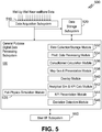
- measured well-by-well near-wellbore data is provided to data acquisition system 510, which couples to general purpose digital data processing (GPDDP) subsystem 530 and to data storage subsystem 520.
- GPSDP general purpose digital data processing
- the measured near-wellbore data is forwarded to GPDDP subsystem 530 for processing and to data storage subsystem 520 for storage and later retrieval.
- data storage subsystem 520 includes the real-time, historical and full-physics numerical simulation results databases of FIG. 3 .
- system 500 is located at a datacenter rather than at or near the reservoir, with the measured near-wellbore data being communicated to the data acquisition system via a communication network (e.g., satellite, telecomm or the Internet).
- GPDDP subsystem 530 also couples to user I/F subsystem 550, which enables a user of the system to interact with the system via such input/output devices as, for example, a keyboard, mouse and display.
- GPDDP subsystem 530 software modules are executed by GPDDP subsystem 530 that each performs various portions of method 400 of FIG. 4 .
- data collection/storage module 532 performs the functions of block 402; production data processing module 534 the functions of block 404; consolidated calculation module 536 the functions of block 406; full-physics numerical simulation module 535 the functions of block 408; map generation and presentation module 538 the functions of blocks 410-412; overlay module 540 the functions of block 414; analytical simulation and KPI calculation module 542 the functions of block 416; and KPI presentation module 544 the functions of block 418.
- the illustrative embodiment of FIG. 5 also includes a deviation detection module 546 that monitors the KPIs and generates an alarm if a KPI value deviates from a reference value (e.g., 1.0 for the voidage replacement ratio) by more than a predetermined threshold value (e.g., ⁇ 0.1).
- a predetermined threshold value e.g., ⁇ 0.1
- such a deviation may alternatively or additionally trigger the generation of an advisory that recommends a specific course of action to correct the deviation (e.g., increasing or decreasing the water injection flow rates at one or more injector wells).
- Some alarms and/or advisories may each be triggered independently when separately defined thresholds are exceeded, while others may be triggered together when a single threshold is exceeded.
- Analytical simulation and KPI calculation module 542 uses the results produced by full-physics simulation module 535 to produce each of the performance indicator values displayed by performance indicator gauges 270-276 of FIG. 2 .
- the performance indicator values of FIG. 2 are calculated as follows:
- volumetric efficiency monitoring provides a macro indication of how much oil is being replaced by water and thus how efficiently the oil is being swept by the water. Displacement efficiency monitoring is similar to volumetric efficient, but instead provides information at a micro or pore level.
- the displayed data provides a measure of the state of the reservoir, an indication of issues as they arise, and information that enables a reservoir operator to diagnose and address the issues in a timely manner. If, for example, the nominal pressure reading of a pattern is below a desired range, a reservoir engineer using the disclosed systems and methods can run a series of simulations, using the current simulated reservoir state as a starting point, to test possible solutions intended to raise the nominal pressure of the pattern.
- the simulated near-wellbore data (e.g., water cut measurements) can be noted and forwarded to field personnel, which may then monitor the measured near-wellbore data after the solution has been applied in the field (e.g., increasing the water injection flow rate at the pattern's injector well) and verify whether the solution is achieving the desired results.
- This enables operators to take further action promptly if necessary if the solution fails to yield the desire results, rather than a month later after the next regular simulation is run integrating the near-wellbore data collected after implementation of the solution.
- the ability to concurrently view and correlate measured near-wellbore data and simulated interwell data may thus be used to more efficiently and effectively exploit reservoirs during production.
- measured near-wellbore values e.g., water cuts
- simulated overall performance indicators e.g., nominal pressure
- simulated interwell data is used to describe simulated data between two or more wells, it is also intended to include simulated data near and/or distanced away from a single well without necessarily being between said well and another well (e.g., simulated data distanced away from a well at the outer edge of a reservoir). It is intended that the following claims be interpreted to embrace all such modifications and alternatives where applicable.
Landscapes
- Engineering & Computer Science (AREA)
- Physics & Mathematics (AREA)
- Life Sciences & Earth Sciences (AREA)
- Geology (AREA)
- Mining & Mineral Resources (AREA)
- Fluid Mechanics (AREA)
- Environmental & Geological Engineering (AREA)
- General Life Sciences & Earth Sciences (AREA)
- Geochemistry & Mineralogy (AREA)
- General Physics & Mathematics (AREA)
- Theoretical Computer Science (AREA)
- Mathematical Analysis (AREA)
- Geometry (AREA)
- Mathematical Optimization (AREA)
- Mathematical Physics (AREA)
- Pure & Applied Mathematics (AREA)
- Computer Hardware Design (AREA)
- Evolutionary Computation (AREA)
- Computing Systems (AREA)
- General Engineering & Computer Science (AREA)
- Algebra (AREA)
- Geophysics (AREA)
- Testing And Monitoring For Control Systems (AREA)
- Testing Or Calibration Of Command Recording Devices (AREA)
- Management, Administration, Business Operations System, And Electronic Commerce (AREA)
Claims (14)
- Verfahren zum Überwachen und Diagnostizieren eines Reservoirs, das Folgendes umfasst:Sammlung von Messdaten in der Nähe eines Bohrlochs, die für Bedingungen an oder nahe einer Mehrzahl von Bohrlöchern innerhalb des Reservoirs repräsentativ sind, und Speicherung der Messdaten in der Nähe eines Bohrlochs in einer oder mehreren Datenbanken;grafische Darstellung von simulierten internen Bohrlochdaten an einen Benutzer, die durch eine Reservoirsimulation zumindest teilweise auf Basis der Messdaten in der Nähe eines Bohrlochs erzeugt werden;grafische Überlagerung von mindestens einigen der Messdaten in der Nähe eines Bohrlochs über die simulierten internen Bohrlochdaten;grafische Darstellung eines oder mehrerer Produktionsindikatoren (270, 272, 274, 276) an den Benutzer, die zumindest teilweise auf Basis der simulierten internen Bohrlochdaten berechnet wurden;Bestimmung einer Abweichung mindestens eines Produktionsindikators (270, 272, 274, 276) von einem Referenzwert; undIdentifizierung und Darstellung einer empfohlenen Aktion an den Benutzer, die für eines oder mehrere der Mehrzahl von Bohrlöchern (240, 242) anwendbar ist, um die Abweichung zu korrigieren, falls die Abweichung einen Schwellenwert überschreitet,wobei die simulierten internen Bohrlochdaten Daten nahe und in einem Abstand von der Mehrzahl von Bohrlöchern (240, 242) enthalten.
- Verfahren nach Anspruch 1, wobei die simulierten internen Bohrlochdaten Wassersättigungsniveaus umfassen.
- Verfahren nach Anspruch 1 oder 2, wobei die zumindest einigen der Messdaten in der Nähe eines Bohrlochs Wassergehalt oder Ölgehalt für jedes von einer oder mehreren Förderbohrungen (202-218, 214-226, 224-236) der Mehrzahl von Bohrlöchern umfassen.
- Verfahren nach Anspruch 1, 2 oder 3, wobei der eine oder die mehreren Produktionsindikatoren (270, 272, 274, 276) einen Indikator umfassen, der aus der Gruppe ausgewählt ist, die aus einem Lückenersatzverhältnis, einem Nenndruck, einem volumetrischen Durchlaufwirkungsgrad und einem Verschiebungswirkungsgrad besteht.
- Verfahren nach einem der vorstehenden Ansprüche, weiter die Darstellung eines oder mehrerer Alarme für den Benutzer umfassend, wenn ein Produktionsindikator (270, 272, 274, 276) um mehr als den oder einen anderen Schwellenwert von dem oder einem anderen Referenzwert abweicht.
- Verfahren nach einem der vorstehenden Ansprüche, wobei die Überlagerung in Echtzeit durchgeführt wird, wenn die Messdaten in der Nähe eines Bohrlochs gesammelt werden.
- Verfahren nach einem der vorstehenden Ansprüche, weiter das Starten der Reservoirsimulation zumindest teilweise auf Basis von einem gespeicherten Simulationsendzustand einer vorherigen Ausführung der Reservoirsimulation umfassend.
- Verfahren nach einem der vorstehenden Ansprüche, weiter das Auswählen eines Reservoirmusters umfassend, das die Mehrzahl von Bohrlöchern (240, 242) umfasst, wobei die dem Benutzer dargestellten Produktionsindikatoren (270, 272, 274, 276) einem oder mehreren Bohrlöchern innerhalb des ausgewählten Musters entsprechen.
- Reservoirüberwachungs- und -diagnosesystem, das Folgendes umfasst:einen Speicher der eine Software zur Überwachung und Diagnose von Reservoiren aufweist; undeinen oder mehrere Prozessoren, die mit dem Speicher verbunden sind, wobei die Software den einen oder die mehreren Prozessoren zu Folgendem veranlasst:Messdaten in der Nähe eines Bohrlochs, die für Bedingungen an oder nahe einer Mehrzahl von Bohrlöchern (240, 242) innerhalb des Reservoirs repräsentativ sind, zu sammeln und die Messdaten in der Nähe eines Bohrlochs in einer oder mehreren Datenbanken zu speichern;einem Benutzer simulierte interne Bohrlochdaten grafisch darzustellen, die durch eine Reservoirsimulation zumindest teilweise auf Basis der Messdaten in der Nähe eines Bohrlochs erzeugt werden;zumindest einige der Messdaten in der Nähe eines Bohrlochs über die simulierten internen Bohrlochdaten grafisch zu überlagern;dem Benutzer grafisch einen oder mehrere Produktionsindikatoren (270, 272, 274, 276) darzustellen, die zumindest teilweise auf Basis der simulierten internen Bohrlochdaten berechnet werden;eine Abweichung von zumindest einem Produktionsindikator (270, 272, 274, 276) von einem Referenzwert zu bestimmen;eine empfohlene Aktion, die für eines oder mehrere der Mehrzahl von Bohrlöchern (240, 242) anwendbar ist, zu identifizieren und dem Benutzer darzustellen, um die Abweichung zu korrigieren, wenn die Abweichung einen Schwellenwert überschreitet,wobei die simulierten internen Bohrlochdaten Daten nahe und in einem Abstand von der Mehrzahl von Bohrlöchern (240, 242) enthalten.
- System nach Anspruch 9, wobei die simulierten internen Bohrlochdaten Wassersättigungsniveaus umfassen.
- System nach Anspruch 9 oder 10, wobei die zumindest einigen der Messdaten in der Nähe eines Bohrlochs Wassergehalt oder Ölgehalt für jede von einer oder mehreren Förderbohrungen der Mehrzahl von Bohrlöchern umfassen.
- System nach Anspruch 9, 10 oder 11, wobei der eine oder die mehreren Produktionsindikatoren (270, 272, 274, 276) einen Indikator umfassen, der aus der Gruppe ausgewählt ist, die aus einem Lückenersatzverhältnis, einem Nenndruck, einem volumetrischen Durchlaufwirkungsgrad und einem Verschiebungswirkungsgrad besteht.
- System nach Anspruch 9, 10, 11 oder 12, wobei die Software weiter veranlasst, dass der eine oder die mehreren Prozessoren dem Benutzer einen oder mehrere Alarme darstellen, wenn ein Produktionsindikator um mehr als den oder einen anderen Schwellenwert von dem oder einem anderen Referenzwert abweicht.
- System nach einem der Ansprüche 9 bis 13, wobei die Software weiter veranlasst, dass der eine oder die mehreren Prozessoren die Überlagerung in Echtzeit durchführen, wenn die Messdaten in der Nähe eines Bohrlochs gesammelt werden.
Applications Claiming Priority (3)
| Application Number | Priority Date | Filing Date | Title |
|---|---|---|---|
| US201261677996P | 2012-07-31 | 2012-07-31 | |
| US13/670,836 US20140039860A1 (en) | 2012-07-31 | 2012-11-07 | Monitoring and Diagnosing Water Flooded Reservoirs Using Production Data |
| PCT/US2013/051385 WO2014022127A1 (en) | 2012-07-31 | 2013-07-19 | Monitoring and diagnosing water flooded reservoirs |
Publications (3)
| Publication Number | Publication Date |
|---|---|
| EP2872736A1 EP2872736A1 (de) | 2015-05-20 |
| EP2872736A4 EP2872736A4 (de) | 2015-10-14 |
| EP2872736B1 true EP2872736B1 (de) | 2018-04-11 |
Family
ID=50026305
Family Applications (1)
| Application Number | Title | Priority Date | Filing Date |
|---|---|---|---|
| EP13826500.4A Not-in-force EP2872736B1 (de) | 2012-07-31 | 2013-07-19 | Überwachung und diagnose von wasserüberfluteten reservoirs |
Country Status (10)
| Country | Link |
|---|---|
| US (1) | US20140039860A1 (de) |
| EP (1) | EP2872736B1 (de) |
| CN (1) | CN104603392A (de) |
| AU (1) | AU2013296908B2 (de) |
| BR (1) | BR112015001985A2 (de) |
| CA (1) | CA2880586C (de) |
| MX (1) | MX2015001074A (de) |
| RU (1) | RU2598261C1 (de) |
| SG (1) | SG11201500354UA (de) |
| WO (1) | WO2014022127A1 (de) |
Cited By (1)
| Publication number | Priority date | Publication date | Assignee | Title |
|---|---|---|---|---|
| CN111022031A (zh) * | 2019-12-16 | 2020-04-17 | 东北石油大学 | 一种井下智能测调工具 |
Families Citing this family (10)
| Publication number | Priority date | Publication date | Assignee | Title |
|---|---|---|---|---|
| US10072485B2 (en) * | 2014-02-12 | 2018-09-11 | Rockwell Automation Asia Pacific Business Center Pte. Ltd. | Systems and methods for localized well analysis and control |
| US10229360B2 (en) | 2015-08-10 | 2019-03-12 | Saudi Arabian Oil Company | Diagnosing reservoir health |
| CA3075989C (en) * | 2017-11-13 | 2022-06-28 | Landmark Graphics Corporation | Simulating fluid production using a reservoir model and a tubing model |
| US10832152B2 (en) | 2017-11-29 | 2020-11-10 | Saudi Arabian Oil Company | Wet well prediction using real time data |
| US10519768B2 (en) * | 2018-02-21 | 2019-12-31 | Saudi Arabian Oil Company | Systems and methods for operating hydrocarbon wells to inhibit breakthrough based on reservoir saturation |
| US12146394B2 (en) | 2018-12-28 | 2024-11-19 | Upwing Energy, Inc. | Controlling downhole-type rotating machines |
| CN111058812B (zh) * | 2019-12-30 | 2024-05-28 | 中国地质大学(武汉) | 一种模拟垮塌堆积储集体边水驱动采油的实验装置 |
| CN113738344B (zh) * | 2020-05-29 | 2024-05-24 | 中国石油化工股份有限公司 | 油水界面深度确定方法及防止生产井水窜的预警方法 |
| US11697989B2 (en) * | 2020-08-27 | 2023-07-11 | Landmark Graphics Corporation | Micro invisible lost time in drilling operations |
| CN115047165B (zh) * | 2022-03-30 | 2025-03-21 | 中海石油(中国)有限公司天津分公司 | 一种水淹级别的确定方法及装置 |
Family Cites Families (8)
| Publication number | Priority date | Publication date | Assignee | Title |
|---|---|---|---|---|
| US6434435B1 (en) * | 1997-02-21 | 2002-08-13 | Baker Hughes Incorporated | Application of adaptive object-oriented optimization software to an automatic optimization oilfield hydrocarbon production management system |
| US6775578B2 (en) * | 2000-09-01 | 2004-08-10 | Schlumberger Technology Corporation | Optimization of oil well production with deference to reservoir and financial uncertainty |
| US6868920B2 (en) * | 2002-12-31 | 2005-03-22 | Schlumberger Technology Corporation | Methods and systems for averting or mitigating undesirable drilling events |
| CN1973110A (zh) * | 2004-06-25 | 2007-05-30 | 国际壳牌研究有限公司 | 从地下地层控制生产碳氢化合物流体用的闭环控制系统 |
| US20090192712A9 (en) * | 2007-02-27 | 2009-07-30 | Hossein Karami | System and method for waterflood performance monitoring |
| US7890264B2 (en) | 2007-10-25 | 2011-02-15 | Schlumberger Technology Corporation | Waterflooding analysis in a subterranean formation |
| US9026417B2 (en) * | 2007-12-13 | 2015-05-05 | Exxonmobil Upstream Research Company | Iterative reservoir surveillance |
| US8306801B2 (en) * | 2009-08-12 | 2012-11-06 | Schlumberger Technology Corporation | Virtual reservoir sensor |
-
2012
- 2012-11-07 US US13/670,836 patent/US20140039860A1/en not_active Abandoned
-
2013
- 2013-07-19 MX MX2015001074A patent/MX2015001074A/es unknown
- 2013-07-19 EP EP13826500.4A patent/EP2872736B1/de not_active Not-in-force
- 2013-07-19 RU RU2015102152/03A patent/RU2598261C1/ru not_active IP Right Cessation
- 2013-07-19 CN CN201380039586.6A patent/CN104603392A/zh active Pending
- 2013-07-19 BR BR112015001985A patent/BR112015001985A2/pt not_active IP Right Cessation
- 2013-07-19 SG SG11201500354UA patent/SG11201500354UA/en unknown
- 2013-07-19 AU AU2013296908A patent/AU2013296908B2/en not_active Ceased
- 2013-07-19 CA CA2880586A patent/CA2880586C/en not_active Expired - Fee Related
- 2013-07-19 WO PCT/US2013/051385 patent/WO2014022127A1/en not_active Ceased
Non-Patent Citations (1)
| Title |
|---|
| None * |
Cited By (2)
| Publication number | Priority date | Publication date | Assignee | Title |
|---|---|---|---|---|
| CN111022031A (zh) * | 2019-12-16 | 2020-04-17 | 东北石油大学 | 一种井下智能测调工具 |
| CN111022031B (zh) * | 2019-12-16 | 2020-08-25 | 东北石油大学 | 一种井下智能测调工具 |
Also Published As
| Publication number | Publication date |
|---|---|
| AU2013296908B2 (en) | 2016-09-29 |
| CA2880586A1 (en) | 2014-02-06 |
| SG11201500354UA (en) | 2015-02-27 |
| CN104603392A (zh) | 2015-05-06 |
| WO2014022127A1 (en) | 2014-02-06 |
| AU2013296908A1 (en) | 2015-02-12 |
| EP2872736A1 (de) | 2015-05-20 |
| EP2872736A4 (de) | 2015-10-14 |
| MX2015001074A (es) | 2015-06-04 |
| BR112015001985A2 (pt) | 2017-07-04 |
| CA2880586C (en) | 2018-07-31 |
| US20140039860A1 (en) | 2014-02-06 |
| RU2598261C1 (ru) | 2016-09-20 |
Similar Documents
| Publication | Publication Date | Title |
|---|---|---|
| EP2872736B1 (de) | Überwachung und diagnose von wasserüberfluteten reservoirs | |
| EP2880405B1 (de) | Operationen für eine elektrische tauchpumpe | |
| EP2867440B1 (de) | Überwachung, diagnose und optimierung von gashebungsoperationen | |
| US8176979B2 (en) | Injection well surveillance system | |
| US8229880B2 (en) | Evaluation of acid fracturing treatments in an oilfield | |
| BR112015009197B1 (pt) | Método e sistema para realizar uma operação de perfuração | |
| EP2844831B1 (de) | Systeme und verfahren zur optimierung einer auf eine anlage begrenzten produktion und injektion in einem integrierten reservoir und einem sammlungsnetzwerk | |
| US12158063B2 (en) | Methods and systems for predicting risk of early-screen-out in near-well zone based on distributed fiber acoustic sensing (DAS) | |
| CN105484724A (zh) | 一种钻井井下异常监测方法 | |
| EP2090742A1 (de) | Verfahren und Systeme zur Schätzung von Bohrlochereignissen |
Legal Events
| Date | Code | Title | Description |
|---|---|---|---|
| PUAI | Public reference made under article 153(3) epc to a published international application that has entered the european phase |
Free format text: ORIGINAL CODE: 0009012 |
|
| 17P | Request for examination filed |
Effective date: 20150128 |
|
| AK | Designated contracting states |
Kind code of ref document: A1 Designated state(s): AL AT BE BG CH CY CZ DE DK EE ES FI FR GB GR HR HU IE IS IT LI LT LU LV MC MK MT NL NO PL PT RO RS SE SI SK SM TR |
|
| AX | Request for extension of the european patent |
Extension state: BA ME |
|
| RA4 | Supplementary search report drawn up and despatched (corrected) |
Effective date: 20150915 |
|
| RIC1 | Information provided on ipc code assigned before grant |
Ipc: E21B 43/16 20060101ALI20150909BHEP Ipc: E21B 47/04 20120101ALI20150909BHEP Ipc: E21B 43/12 20060101AFI20150909BHEP Ipc: G06F 17/10 20060101ALI20150909BHEP |
|
| DAX | Request for extension of the european patent (deleted) | ||
| 17Q | First examination report despatched |
Effective date: 20160805 |
|
| GRAP | Despatch of communication of intention to grant a patent |
Free format text: ORIGINAL CODE: EPIDOSNIGR1 |
|
| INTG | Intention to grant announced |
Effective date: 20171208 |
|
| GRAS | Grant fee paid |
Free format text: ORIGINAL CODE: EPIDOSNIGR3 |
|
| GRAA | (expected) grant |
Free format text: ORIGINAL CODE: 0009210 |
|
| AK | Designated contracting states |
Kind code of ref document: B1 Designated state(s): AL AT BE BG CH CY CZ DE DK EE ES FI FR GB GR HR HU IE IS IT LI LT LU LV MC MK MT NL NO PL PT RO RS SE SI SK SM TR |
|
| REG | Reference to a national code |
Ref country code: GB Ref legal event code: FG4D |
|
| REG | Reference to a national code |
Ref country code: CH Ref legal event code: EP |
|
| REG | Reference to a national code |
Ref country code: AT Ref legal event code: REF Ref document number: 988234 Country of ref document: AT Kind code of ref document: T Effective date: 20180415 |
|
| REG | Reference to a national code |
Ref country code: IE Ref legal event code: FG4D |
|
| REG | Reference to a national code |
Ref country code: DE Ref legal event code: R096 Ref document number: 602013035862 Country of ref document: DE |
|
| REG | Reference to a national code |
Ref country code: NO Ref legal event code: T2 Effective date: 20180411 |
|
| REG | Reference to a national code |
Ref country code: FR Ref legal event code: PLFP Year of fee payment: 6 |
|
| REG | Reference to a national code |
Ref country code: NL Ref legal event code: MP Effective date: 20180411 |
|
| REG | Reference to a national code |
Ref country code: LT Ref legal event code: MG4D |
|
| PG25 | Lapsed in a contracting state [announced via postgrant information from national office to epo] |
Ref country code: NL Free format text: LAPSE BECAUSE OF FAILURE TO SUBMIT A TRANSLATION OF THE DESCRIPTION OR TO PAY THE FEE WITHIN THE PRESCRIBED TIME-LIMIT Effective date: 20180411 |
|
| PG25 | Lapsed in a contracting state [announced via postgrant information from national office to epo] |
Ref country code: ES Free format text: LAPSE BECAUSE OF FAILURE TO SUBMIT A TRANSLATION OF THE DESCRIPTION OR TO PAY THE FEE WITHIN THE PRESCRIBED TIME-LIMIT Effective date: 20180411 Ref country code: AL Free format text: LAPSE BECAUSE OF FAILURE TO SUBMIT A TRANSLATION OF THE DESCRIPTION OR TO PAY THE FEE WITHIN THE PRESCRIBED TIME-LIMIT Effective date: 20180411 Ref country code: FI Free format text: LAPSE BECAUSE OF FAILURE TO SUBMIT A TRANSLATION OF THE DESCRIPTION OR TO PAY THE FEE WITHIN THE PRESCRIBED TIME-LIMIT Effective date: 20180411 Ref country code: LT Free format text: LAPSE BECAUSE OF FAILURE TO SUBMIT A TRANSLATION OF THE DESCRIPTION OR TO PAY THE FEE WITHIN THE PRESCRIBED TIME-LIMIT Effective date: 20180411 Ref country code: BG Free format text: LAPSE BECAUSE OF FAILURE TO SUBMIT A TRANSLATION OF THE DESCRIPTION OR TO PAY THE FEE WITHIN THE PRESCRIBED TIME-LIMIT Effective date: 20180711 Ref country code: PL Free format text: LAPSE BECAUSE OF FAILURE TO SUBMIT A TRANSLATION OF THE DESCRIPTION OR TO PAY THE FEE WITHIN THE PRESCRIBED TIME-LIMIT Effective date: 20180411 Ref country code: SE Free format text: LAPSE BECAUSE OF FAILURE TO SUBMIT A TRANSLATION OF THE DESCRIPTION OR TO PAY THE FEE WITHIN THE PRESCRIBED TIME-LIMIT Effective date: 20180411 |
|
| PG25 | Lapsed in a contracting state [announced via postgrant information from national office to epo] |
Ref country code: GR Free format text: LAPSE BECAUSE OF FAILURE TO SUBMIT A TRANSLATION OF THE DESCRIPTION OR TO PAY THE FEE WITHIN THE PRESCRIBED TIME-LIMIT Effective date: 20180712 Ref country code: HR Free format text: LAPSE BECAUSE OF FAILURE TO SUBMIT A TRANSLATION OF THE DESCRIPTION OR TO PAY THE FEE WITHIN THE PRESCRIBED TIME-LIMIT Effective date: 20180411 Ref country code: LV Free format text: LAPSE BECAUSE OF FAILURE TO SUBMIT A TRANSLATION OF THE DESCRIPTION OR TO PAY THE FEE WITHIN THE PRESCRIBED TIME-LIMIT Effective date: 20180411 Ref country code: RS Free format text: LAPSE BECAUSE OF FAILURE TO SUBMIT A TRANSLATION OF THE DESCRIPTION OR TO PAY THE FEE WITHIN THE PRESCRIBED TIME-LIMIT Effective date: 20180411 |
|
| REG | Reference to a national code |
Ref country code: AT Ref legal event code: MK05 Ref document number: 988234 Country of ref document: AT Kind code of ref document: T Effective date: 20180411 |
|
| PG25 | Lapsed in a contracting state [announced via postgrant information from national office to epo] |
Ref country code: PT Free format text: LAPSE BECAUSE OF FAILURE TO SUBMIT A TRANSLATION OF THE DESCRIPTION OR TO PAY THE FEE WITHIN THE PRESCRIBED TIME-LIMIT Effective date: 20180813 |
|
| REG | Reference to a national code |
Ref country code: DE Ref legal event code: R097 Ref document number: 602013035862 Country of ref document: DE |
|
| PG25 | Lapsed in a contracting state [announced via postgrant information from national office to epo] |
Ref country code: CZ Free format text: LAPSE BECAUSE OF FAILURE TO SUBMIT A TRANSLATION OF THE DESCRIPTION OR TO PAY THE FEE WITHIN THE PRESCRIBED TIME-LIMIT Effective date: 20180411 Ref country code: RO Free format text: LAPSE BECAUSE OF FAILURE TO SUBMIT A TRANSLATION OF THE DESCRIPTION OR TO PAY THE FEE WITHIN THE PRESCRIBED TIME-LIMIT Effective date: 20180411 Ref country code: SK Free format text: LAPSE BECAUSE OF FAILURE TO SUBMIT A TRANSLATION OF THE DESCRIPTION OR TO PAY THE FEE WITHIN THE PRESCRIBED TIME-LIMIT Effective date: 20180411 Ref country code: EE Free format text: LAPSE BECAUSE OF FAILURE TO SUBMIT A TRANSLATION OF THE DESCRIPTION OR TO PAY THE FEE WITHIN THE PRESCRIBED TIME-LIMIT Effective date: 20180411 Ref country code: AT Free format text: LAPSE BECAUSE OF FAILURE TO SUBMIT A TRANSLATION OF THE DESCRIPTION OR TO PAY THE FEE WITHIN THE PRESCRIBED TIME-LIMIT Effective date: 20180411 Ref country code: DK Free format text: LAPSE BECAUSE OF FAILURE TO SUBMIT A TRANSLATION OF THE DESCRIPTION OR TO PAY THE FEE WITHIN THE PRESCRIBED TIME-LIMIT Effective date: 20180411 |
|
| REG | Reference to a national code |
Ref country code: DE Ref legal event code: R119 Ref document number: 602013035862 Country of ref document: DE |
|
| PLBE | No opposition filed within time limit |
Free format text: ORIGINAL CODE: 0009261 |
|
| STAA | Information on the status of an ep patent application or granted ep patent |
Free format text: STATUS: NO OPPOSITION FILED WITHIN TIME LIMIT |
|
| PG25 | Lapsed in a contracting state [announced via postgrant information from national office to epo] |
Ref country code: IT Free format text: LAPSE BECAUSE OF FAILURE TO SUBMIT A TRANSLATION OF THE DESCRIPTION OR TO PAY THE FEE WITHIN THE PRESCRIBED TIME-LIMIT Effective date: 20180411 Ref country code: SM Free format text: LAPSE BECAUSE OF FAILURE TO SUBMIT A TRANSLATION OF THE DESCRIPTION OR TO PAY THE FEE WITHIN THE PRESCRIBED TIME-LIMIT Effective date: 20180411 |
|
| REG | Reference to a national code |
Ref country code: CH Ref legal event code: PL |
|
| 26N | No opposition filed |
Effective date: 20190114 |
|
| PG25 | Lapsed in a contracting state [announced via postgrant information from national office to epo] |
Ref country code: MC Free format text: LAPSE BECAUSE OF FAILURE TO SUBMIT A TRANSLATION OF THE DESCRIPTION OR TO PAY THE FEE WITHIN THE PRESCRIBED TIME-LIMIT Effective date: 20180411 Ref country code: LU Free format text: LAPSE BECAUSE OF NON-PAYMENT OF DUE FEES Effective date: 20180719 |
|
| REG | Reference to a national code |
Ref country code: BE Ref legal event code: MM Effective date: 20180731 |
|
| REG | Reference to a national code |
Ref country code: IE Ref legal event code: MM4A |
|
| PG25 | Lapsed in a contracting state [announced via postgrant information from national office to epo] |
Ref country code: DE Free format text: LAPSE BECAUSE OF NON-PAYMENT OF DUE FEES Effective date: 20190201 Ref country code: IE Free format text: LAPSE BECAUSE OF NON-PAYMENT OF DUE FEES Effective date: 20180719 Ref country code: LI Free format text: LAPSE BECAUSE OF NON-PAYMENT OF DUE FEES Effective date: 20180731 Ref country code: CH Free format text: LAPSE BECAUSE OF NON-PAYMENT OF DUE FEES Effective date: 20180731 |
|
| PG25 | Lapsed in a contracting state [announced via postgrant information from national office to epo] |
Ref country code: SI Free format text: LAPSE BECAUSE OF FAILURE TO SUBMIT A TRANSLATION OF THE DESCRIPTION OR TO PAY THE FEE WITHIN THE PRESCRIBED TIME-LIMIT Effective date: 20180411 Ref country code: BE Free format text: LAPSE BECAUSE OF NON-PAYMENT OF DUE FEES Effective date: 20180731 |
|
| PGFP | Annual fee paid to national office [announced via postgrant information from national office to epo] |
Ref country code: FR Payment date: 20190730 Year of fee payment: 7 Ref country code: GB Payment date: 20190610 Year of fee payment: 7 |
|
| PG25 | Lapsed in a contracting state [announced via postgrant information from national office to epo] |
Ref country code: MT Free format text: LAPSE BECAUSE OF NON-PAYMENT OF DUE FEES Effective date: 20180719 |
|
| PG25 | Lapsed in a contracting state [announced via postgrant information from national office to epo] |
Ref country code: TR Free format text: LAPSE BECAUSE OF FAILURE TO SUBMIT A TRANSLATION OF THE DESCRIPTION OR TO PAY THE FEE WITHIN THE PRESCRIBED TIME-LIMIT Effective date: 20180411 |
|
| PG25 | Lapsed in a contracting state [announced via postgrant information from national office to epo] |
Ref country code: HU Free format text: LAPSE BECAUSE OF FAILURE TO SUBMIT A TRANSLATION OF THE DESCRIPTION OR TO PAY THE FEE WITHIN THE PRESCRIBED TIME-LIMIT; INVALID AB INITIO Effective date: 20130719 |
|
| PG25 | Lapsed in a contracting state [announced via postgrant information from national office to epo] |
Ref country code: MK Free format text: LAPSE BECAUSE OF NON-PAYMENT OF DUE FEES Effective date: 20180411 Ref country code: CY Free format text: LAPSE BECAUSE OF FAILURE TO SUBMIT A TRANSLATION OF THE DESCRIPTION OR TO PAY THE FEE WITHIN THE PRESCRIBED TIME-LIMIT Effective date: 20180411 |
|
| PG25 | Lapsed in a contracting state [announced via postgrant information from national office to epo] |
Ref country code: IS Free format text: LAPSE BECAUSE OF FAILURE TO SUBMIT A TRANSLATION OF THE DESCRIPTION OR TO PAY THE FEE WITHIN THE PRESCRIBED TIME-LIMIT Effective date: 20180811 |
|
| PGFP | Annual fee paid to national office [announced via postgrant information from national office to epo] |
Ref country code: NO Payment date: 20200625 Year of fee payment: 8 |
|
| GBPC | Gb: european patent ceased through non-payment of renewal fee |
Effective date: 20200719 |
|
| PG25 | Lapsed in a contracting state [announced via postgrant information from national office to epo] |
Ref country code: GB Free format text: LAPSE BECAUSE OF NON-PAYMENT OF DUE FEES Effective date: 20200719 Ref country code: FR Free format text: LAPSE BECAUSE OF NON-PAYMENT OF DUE FEES Effective date: 20200731 |
|
| REG | Reference to a national code |
Ref country code: NO Ref legal event code: MMEP |
|
| PG25 | Lapsed in a contracting state [announced via postgrant information from national office to epo] |
Ref country code: NO Free format text: LAPSE BECAUSE OF NON-PAYMENT OF DUE FEES Effective date: 20210731 |