EP2872726B1 - Système de poussée à piston de tube dans tube - Google Patents
Système de poussée à piston de tube dans tube Download PDFInfo
- Publication number
- EP2872726B1 EP2872726B1 EP12881023.1A EP12881023A EP2872726B1 EP 2872726 B1 EP2872726 B1 EP 2872726B1 EP 12881023 A EP12881023 A EP 12881023A EP 2872726 B1 EP2872726 B1 EP 2872726B1
- Authority
- EP
- European Patent Office
- Prior art keywords
- piston assembly
- wellbore
- piston
- pass
- pipe
- Prior art date
- Legal status (The legal status is an assumption and is not a legal conclusion. Google has not performed a legal analysis and makes no representation as to the accuracy of the status listed.)
- Not-in-force
Links
- 239000012530 fluid Substances 0.000 claims description 62
- 230000000712 assembly Effects 0.000 claims description 39
- 238000000429 assembly Methods 0.000 claims description 39
- 238000005553 drilling Methods 0.000 claims description 21
- 238000004891 communication Methods 0.000 claims description 20
- 238000000034 method Methods 0.000 claims description 19
- 238000010168 coupling process Methods 0.000 claims description 15
- 238000005859 coupling reaction Methods 0.000 claims description 15
- 230000008878 coupling Effects 0.000 claims description 14
- 230000007246 mechanism Effects 0.000 claims description 8
- 238000012546 transfer Methods 0.000 claims description 4
- 230000037361 pathway Effects 0.000 claims description 3
- 238000011144 upstream manufacturing Methods 0.000 claims description 3
- 230000007423 decrease Effects 0.000 claims description 2
- 230000004044 response Effects 0.000 claims description 2
- 230000003247 decreasing effect Effects 0.000 claims 1
- 230000005611 electricity Effects 0.000 claims 1
- 230000015572 biosynthetic process Effects 0.000 description 25
- 238000005755 formation reaction Methods 0.000 description 25
- 238000007789 sealing Methods 0.000 description 8
- 238000003825 pressing Methods 0.000 description 7
- 230000003993 interaction Effects 0.000 description 4
- 238000004519 manufacturing process Methods 0.000 description 4
- 238000005086 pumping Methods 0.000 description 4
- 229910000831 Steel Inorganic materials 0.000 description 3
- 239000010959 steel Substances 0.000 description 3
- 239000004568 cement Substances 0.000 description 2
- 239000004020 conductor Substances 0.000 description 2
- 229930195733 hydrocarbon Natural products 0.000 description 2
- 150000002430 hydrocarbons Chemical class 0.000 description 2
- 230000001681 protective effect Effects 0.000 description 2
- 239000004215 Carbon black (E152) Substances 0.000 description 1
- 230000003466 anti-cipated effect Effects 0.000 description 1
- 230000008859 change Effects 0.000 description 1
- 238000006243 chemical reaction Methods 0.000 description 1
- 238000007667 floating Methods 0.000 description 1
- 238000011065 in-situ storage Methods 0.000 description 1
- 238000002347 injection Methods 0.000 description 1
- 239000007924 injection Substances 0.000 description 1
- 238000002955 isolation Methods 0.000 description 1
- 208000020442 loss of weight Diseases 0.000 description 1
- 239000002184 metal Substances 0.000 description 1
- 238000012986 modification Methods 0.000 description 1
- 230000004048 modification Effects 0.000 description 1
- 239000000615 nonconductor Substances 0.000 description 1
- 229910052755 nonmetal Inorganic materials 0.000 description 1
- 230000035515 penetration Effects 0.000 description 1
- 239000012466 permeate Substances 0.000 description 1
- 239000000243 solution Substances 0.000 description 1
- 239000003381 stabilizer Substances 0.000 description 1
- 230000007704 transition Effects 0.000 description 1
- XLYOFNOQVPJJNP-UHFFFAOYSA-N water Substances O XLYOFNOQVPJJNP-UHFFFAOYSA-N 0.000 description 1
Images


Classifications
-
- E—FIXED CONSTRUCTIONS
- E21—EARTH OR ROCK DRILLING; MINING
- E21B—EARTH OR ROCK DRILLING; OBTAINING OIL, GAS, WATER, SOLUBLE OR MELTABLE MATERIALS OR A SLURRY OF MINERALS FROM WELLS
- E21B33/00—Sealing or packing boreholes or wells
- E21B33/10—Sealing or packing boreholes or wells in the borehole
- E21B33/12—Packers; Plugs
- E21B33/124—Units with longitudinally-spaced plugs for isolating the intermediate space
-
- E—FIXED CONSTRUCTIONS
- E21—EARTH OR ROCK DRILLING; MINING
- E21B—EARTH OR ROCK DRILLING; OBTAINING OIL, GAS, WATER, SOLUBLE OR MELTABLE MATERIALS OR A SLURRY OF MINERALS FROM WELLS
- E21B23/00—Apparatus for displacing, setting, locking, releasing or removing tools, packers or the like in boreholes or wells
- E21B23/08—Introducing or running tools by fluid pressure, e.g. through-the-flow-line tool systems
-
- E—FIXED CONSTRUCTIONS
- E21—EARTH OR ROCK DRILLING; MINING
- E21B—EARTH OR ROCK DRILLING; OBTAINING OIL, GAS, WATER, SOLUBLE OR MELTABLE MATERIALS OR A SLURRY OF MINERALS FROM WELLS
- E21B4/00—Drives for drilling, used in the borehole
- E21B4/18—Anchoring or feeding in the borehole
Definitions
- Pipe in pipe piston thrust assemblies can be used to provide thrust for a drill bit in a wellbore when, for example, the weight of the tubular string is insufficient to advance the tubular string through a wellbore.
- weight applied to the drill bit may be lost. In these cases, the drill bit can no longer effectively bore further through the subterranean formation.
- US 2008/0128128 A1 discloses a method and apparatus for conveying an electrically energized hydraulic pump into a wellbore surrounded by steel casing and thereafter using that hydraulic pump to pump oil, water and gas to the surface of the earth.
- the apparatus may be used as a well tractor conveyance system to service a perforated steel cased wellbore located in a geological formation that incorporates means to prevent any reverse fluid flow into the geological formation through any perforations in the steel cased wellbore during movement within the wellbore of the tractor conveyance means.
- US 2008/0128128 A1 does not disclose a by-pass disposed between a plurality of annuli formed by a plurality of piston assemblies, wherein the by-pass allows for selective communication of the fluid between the plurality of annuli and for selective creation of differential pressures across the plurality of piston assemblies.
- US 5,060,737 discloses a drilling system comprising a drill string incorporating inbuilt tubular conductors, a mud supply passage, and passages for protective and other fluids.
- the drill string can be advanced by selectively actuable pistons exposed to drilling mud flow, by electrically driven traction units engaging the drill hole wall or by a linear electric motor element cooperating with a drill hole casing, which can be moved thereby relative to the drill string.
- WO 2011/005107 A2 discloses a downhole well tool provided with a piston, and US 3 957 119 A discloses a pump down method.
- a pipe in pipe piston thrust system comprising: a plurality of piston assemblies configured to sealingly engage a wellbore; a pump configured to transfer a fluid into the wellbore; and a by-pass disposed between a plurality of annuli formed by the plurality of piston assemblies, wherein the by-pass allows for selective communication of the fluid between the plurality of annuli and for selective creation of differential pressures across the plurality of piston asssemblies.
- a method for traversing a leak path comprising: closing a first by-pass through a first piston assembly, wherein the first piston assembly is disposed in a wellbore and sealingly engages the wellbore; opening a second by-pass through a second piston assembly to provide fluid communication to the first piston assembly, wherein the second piston assembly is disposed in the wellbore and sealingly engages the wellbore; axially displacing the first piston assembly and the second piston assembly in a first direction in a wellbore by increasing pressure across the first piston assembly; closing the second by-pass through the second piston assembly; providing a pressure differential across the second piston assembly; and axially displacing the first piston assembly in the first direction past a lateral path based on the pressure differential across the second piston assembly.
- any use of any form of the terms “connect,” “engage,” “couple,” “attach,” or any other term describing an interaction between elements is not meant to limit the interaction to direct interaction between the elements and may also include indirect interaction between the elements described.
- the terms “including” and “comprising” are used in an open-ended fashion, and thus should be interpreted to mean “including, but not limited to ". Reference to up or down will be made for purposes of description with “up,” “upper,” “upward,” or “upstream” meaning toward the surface of the wellbore and with “down,” “lower,” “downward,” or “downstream” meaning toward the terminal end of the well, regardless of the wellbore orientation.
- references to in or out will be made for purposes of description with “in,” “inner,” or “inward” meaning toward the center or central axis of the wellbore, and with “out,” “outer,” or “outward” meaning toward the wellbore tubular and/or wall of the wellbore.
- Reference to "longitudinal,” “longitudinally,” or “axially” means a direction substantially aligned with the main axis of the wellbore and/or wellbore tubular.
- Reference to "radial” or “radially” means a direction substantially aligned with a line between the main axis of the wellbore and/or wellbore tubular and the wellbore wall that is substantially normal to the main axis of the wellbore and/or wellbore tubular, though the radial direction does not have to pass through the central axis of the wellbore and/or wellbore tubular.
- Traditional drilling systems utilize a drill bit disposed on the end of a drill string to form a wellbore in a subterranean formation.
- Force can be applied to the drill bit to engage the drill bit with the subterranean formation, which may be referred to as applying weight to the drill bit.
- the force is usually applied by lowering the drill string to allow a portion of the weight of the drill string to be applied to the drill bit.
- the drill string may experience drag forces due to contact with the wellbore walls. This make applying weight to the drill bit by simply lowering the drill string difficult and unreliable.
- One solution involves the use of a piston tractor system comprising two pistons to apply a force to the drill bit based on hydraulic pressure.
- a pipe in pipe piston thrust system having pull and push through coupling designs for use with a wellbore tubular that may be used to bypass various leak paths and/or maintain force on a drill bit or tool within the wellbore.
- the pipe in pipe piston thrust system described herein may be coupled to a wellbore tubular through the use of tubular string, thereby coupling the pipe in pipe piston thrust system to the wellbore tubular. Drilling with reel-well like systems requires the weight applied to the bit to be primarily controlled by pressure behind a piston in a casing or liner section behind the interval being drilled.
- a lateral path may be sealed to fluid flow, but the presence of the lateral path may be sufficient to disrupt the seal formed between a piston and the wellbore. Once the piston is past the sealed lateral path, the seal may be reformed and any fluid in communication with the sealed pathway may be used to apply pressure to the piston.
- lateral breaks may be referred to as lateral breaks.
- a pipe in pipe piston thrust system may be implemented to overcome these obstacles.
- the pipe in pipe piston thrust system comprises a plurality of piston assemblies which selectively sealingly engage a wellbore.
- a plurality of annuli can be formed between a wellbore tubular, the wellbore wall and/or a casing inner surface, and the plurality of piston assemblies.
- the plurality of annuli can be disposed longitudinally above, below, and/or between the plurality of piston assemblies, though in some embodiments described herein, a plurality of radial annuli may also be present.
- a by-pass may be disposed between the plurality of annuli, where the by-pass allows for the selective communication of a fluid between the plurality of annuli.
- the pipe in pipe piston thrust system further comprises a pump which transfers fluid into the wellbore. Additionally, the pipe in pipe piston thrust system may comprise a selectively fixed attachment of the plurality of piston assemblies to a tubular string.
- a first piston assembly may be disposed within and sealingly engaged with the wellbore.
- a by-pass in the first piston assembly may be disposed in the closed position.
- pressure may be increased across the first piston assembly. This may be carried out by pumping fluid on top of the first piston assembly.
- the first piston assembly may be axially displaced in the downstream direction through the wellbore.
- a second piston assembly may be selectively sealingly engaged with the wellbore. Similar to the first piston assembly, pressure may be increased across the second piston assembly by pumping fluid on top of the second piston assembly.
- the by-pass of the second piston assembly may then by placed in the open position so that fluid may communicate with the annulus between the first and second piston assemblies applying pressure on the first piston assembly in order to apply weight as close as possible to the drill bit.
- the annulus comprises the distance, for example, between the top of the first piston assembly and the bottom of the second piston assembly.
- the annulus also comprises the distance between the outer wall of the tubular string and the wall of the wellbore or the wellbore casing.
- the first and the second piston assemblies then may be axially displaced in the downstream direction through the wellbore so that the first piston assembly reaches a leak path. The leak path allows fluid to leak through the wellbore wall and into the subterranean and thus pressure is lost across the first piston assembly.
- the piston assemblies may not be pressured to drive the drill bit through the wellbore.
- the by-pass on the first piston assembly may be disposed into the open position.
- the second piston assembly may be disposed to the closed position. This creates a differential pressure across the second piston assembly allowing for the weight to be applied again to drive the drill bit.
- a first piston assembly may be disposed within and selectively sealingly engaged with the wellbore.
- a by-pass in the first piston assembly may be disposed in the closed position.
- pressure may be increased across the first piston assembly. This may be carried out by pumping fluid on top of the first piston assembly.
- the first piston assembly may be axially displaced in the downstream direction through the wellbore.
- a second piston assembly may be selectively sealingly engaged with the wellbore.
- pressure may be increased across the second piston assembly by pumping fluid on top of the second piston assembly.
- the by-pass of the second piston assembly may then by placed in the open position so that fluid may communicate with the annulus between the first and second piston assemblies applying pressure on the first piston assembly in order to apply weight as close as possible to the drill bit.
- the first and the second piston assemblies then may be axially displaced in the downstream direction through the wellbore so that the first piston assembly reaches a lateral break.
- the lateral break breaks the seal between the first piston assembly and the wellbore so that pressure is lost across the first piston assembly. With the lateral break, fluid does not leak through the walls of the wellbore and into the subterranean formations.
- the piston assemblies are not pressured to drive the drill bit through the wellbore.
- the by-pass of the first piston assembly may be placed in the open position.
- the by-pass of the second piston assembly may be placed in the closed position to create a differential pressure across the second piston assembly allowing for the weight to be applied again to drive the drill bit.
- the first and the second piston assemblies may then be axially displaced in the downstream direction through the wellbore so that first piston assembly passes the lateral break and reseals with the wellbore.
- the by-pass of the first piston assembly may be place back in the closed position and the by-pass of the second piston assembly may be placed in the open position so that fluid may again communicate to the first piston assembly applying pressure on the first piston assembly to drive the drill bit.
- the selectively fixed attachment of the plurality of piston assemblies may be selectively released from the tubular string.
- the piston assemblies may then stack within the wellbore (e.g., on a shoulder formed by the reduced diameter).
- multiple piston assemblies may be added to the tubular string as it is lowered in the wellbore. Any extra piston assemblies may serve as back-ups or redundant systems for use in the event that a piston assembly fails and/or when a piston assembly is selectively released from the tubular string within the wellbore.
- the piston assemblies that have been released may be selectively reengaged as the tubular string is withdrawn from the wellbore, thus providing redundant piston assemblies that can be attached within the wellbore when the tubular string is conveyed out of the wellbore.
- the pipe in pipe piston thrust system provides the opportunity for several advantages.
- the pipe in pipe piston thrust system allows pressure on a drill bit even in the presence of leak paths and lateral breaks. Previous drilling assemblies may have lost pressure on the drill bit when encountering leak paths or lateral breaks. Additionally, the pipe in pipe piston thrust system allows for continued drilling beyond the leak path or lateral break by traversing the leak path or lateral break. Previous drilling assemblies may not have been able to traverse leak paths or lateral breaks because they were not able to retain pressure on the drill bit beyond the leak path or lateral break. Finally, the pipe in pipe piston thrust system can be easily automated for fast reactions to drops in pressure on drill bits.
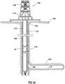
- the operating environment comprises a drilling rig 106 that is positioned on the earth's surface 104 and extends over and around a wellbore 114 that penetrates a subterranean formation 102 for the purpose of recovering hydrocarbons.
- the wellbore 114 may be drilled into the subterranean formation 102 using any suitable drilling technique.
- the wellbore 114 extends substantially vertically away from the earth's surface 104 over a vertical wellbore portion 116, deviates from vertical relative to the earth's surface 104 over a deviated wellbore portion 136, and transitions to a horizontal wellbore portion 118.
- a wellbore may be vertical, deviated at any suitable angle, horizontal, and/or curved.
- the wellbore may be a new wellbore, an existing wellbore, a straight wellbore, an extended reach wellbore, a sidetracked wellbore, a multi-lateral wellbore, and other types of wellbores for drilling and completing one or more production zones.
- the wellbore may be used for both producing wells and injection wells.
- the wellbore may be used for purposes other than or in addition to hydrocarbon production, such as uses related to geothermal energy.
- a wellbore tubular string 120 comprising a pipe in pipe piston thrust system 10 may be lowered into the subterranean formation 102 for a variety of workover or treatment procedures throughout the life of the wellbore.
- the embodiment shown in Figure 1A illustrates the wellbore tubular 120 in the form of a casing string being lowered into the subterranean formation 102.
- the wellbore tubular 120 comprising a pipe in pipe piston thrust system 10 is equally applicable to any type of wellbore tubular being inserted into a wellbore, including as non-limiting examples drill pipe, production tubing, rod strings, and coiled tubing.
- the pipe in pipe piston thrust system 10 may also be used to centralize various subs and workover tools. In the embodiment shown in Figure.
- the wellbore tubular 120 comprising the pipe in pipe piston thrust system 10 is conveyed into the subterranean formation 102 in a conventional manner and may subsequently be secured within the wellbore 114 by filling an annulus 112 between the wellbore tubular 120 and the wellbore 114 with cement.
- the drilling rig 106 comprises a derrick 108 with a rig floor 110 through which the wellbore tubular 120 extends downward from the drilling rig 106 into the wellbore 114.
- the drilling rig 106 comprises a motor driven winch and other associated equipment for extending the wellbore tubular 120 into the wellbore 114 to position the wellbore tubular 120 at a selected depth.
- FIG. 1A refers to a stationary drilling rig 106 for lowering and setting the wellbore tubular 120 comprising the pipe in pipe piston thrust system 10 within a land-based wellbore 114
- mobile workover rigs such as coiled tubing units
- wellbore servicing units such as coiled tubing units
- a wellbore tubular 120 comprising the pipe in pipe piston thrust system 10 may alternatively be used in other operational environments, such as within an offshore wellbore operational environment.
- a vertical, deviated, or horizontal wellbore portion may be cased and cemented and/or portions of the wellbore may be uncased.
- uncased section 140 may comprise a section of the wellbore 114 ready for being cased with wellbore tubular 120.
- a pipe in pipe piston thrust system 10 may be used on production tubing in a cased or uncased wellbore.
- a portion of the wellbore 114 may comprise an underreamed section.
- underreaming refers to the enlargement of an existing wellbore below an existing section, which may be cased in some embodiments.
- An underreamed section may have a larger diameter than a section above the underreamed section.
- a wellbore tubular passing down through the wellbore may pass through a smaller diameter passage followed by a larger diameter passage.
- casing is used herein to indicate a protective lining for a wellbore. Casing can serve to prevent collapse of a wellbore, to provide pressure isolation, etc..
- Casing can include tubulars known to those skilled in the art as casing, liner or tubing. Casing can be segmented or continuous, metal or nonmetal, and can be preformed or formed in situ. Any type of tubular may be used, in keeping with the principles of this disclosure.
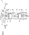
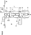
- an embodiment of the pipe in pipe piston thrust system 10 depicts a first piston assembly 12 and a second piston assembly 14 selectively sealingly engaging a wellbore 16.
- the first piston assembly 12 and the second piston assembly 14 may also slidingly sealingly engage the wellbore 16.
- the pipe in pipe piston thrust system 10 could be positioned in an uncased, open hole section of the wellbore 16 (e.g., the section of the wellbore being drilled in FIG. 1B ).
- the pipe in pipe piston thrust system 10 can be positioned in a cased section of the wellbore 16 lined with a casing and cement so that the first piston assembly 12 and the second piston assembly 14 may selectively sealingly engage the cased section of the wellbore 16.
- a first by-pass 18A disposed on the first piston assembly 12 allows for the selective communication of a fluid 20 between the first annulus 22 disposed downstream of the first piston assembly 12 and a second annulus 24 disposed between the second piston assembly 14 and the first piston assembly 12.
- Each by-pass, such as by-passes 18A and 18B, comprise one or more selectively actuatable flow paths to permit fluid communication between annuli.
- the first annulus 22 and the second annulus 24 may be formed between the tubular string 32 and the wellbore/casing wall.
- a pump 26 disposed on the surface 28 transfers the fluid 20 into the wellbore 16 and into a third annulus 30 disposed between the surface 28 and the second piston assembly 14.
- the third annulus 30 may be formed between the tubular string 32 and the wellbore/casing wall.
- the pump 26 may be disposed on another surface location such as, a rig at the earth's surface, a subsea facility, or a floating rig.
- the pump 26 previously pumped fluid 20 into the first annulus 22 and the second annulus 24 before the second piston assembly 14 was selectively sealingly engaged in the wellbore 16 so that fluid 20 filled the first annulus 22 and the second annulus 24.
- a second by-pass 18B may be disposed on the second piston assembly 14 allowing for selective communication of the fluid 20 between the third annulus 30 and the second annulus 24.
- a tubular string 32 may be disposed axially in the wellbore 16.
- a drill bit 34 may be located at the distal end of the tubular string 32 in the wellbore 16.
- the first piston assembly 12 and the second piston assembly 14 fixedly sealingly engage the tubular string 32.
- first piston assembly 12 and the second piston assembly 14 selectively sealingly engage the tubular string 32 and axially reciprocate along the tubular string 32.
- a coupling mechanism may be used to selectively sealingly engage the first piston assembly 12 and the second piston assembly 14 with the tubular string 32.
- the coupling mechanism may be operated in response to a sensed drilling operation.
- the coupling mechanism may comprise a latching and de-latching system.
- the de-latching system would be activated by a shear force across the piston such that if the shear force across the piston from the diameter change in the hole exceeds a desired threshold the piston unlatches or shears a shear pin which was holding the piston to the outer pipe in its relative position.
- the coupling mechanism may have fixed latch points where re-coupling may occur. In an embodiment, it may also be desirable to have a permanent decoupling of the piston from the outer pipe.
- the coupling mechanism may allow the first piston assembly 12 and the second piston assembly 14 to selectively sealingly engage anywhere axially along the tubular string 32, and/or the coupling mechanism may allow the first piston assembly 12 and the second piston assembly 14 to selectively sealingly engage at predetermined points along the axis of the tubular string 32.
- the coupling system may receive a signal from a control system 56 depicted in Figure ID to selectively sealingly engage the first piston assembly 12 and/or the second piston assembly 14 with the tubular string 32.
- fluid 20 pumped from pump 26 creates a pressure differential across the second piston assembly 14 and, for example, drives drill bit 34 and the tubular string 32 through the subterranean formation 36.
- the pipe in pipe piston thrust system 10 may be used to advance the tubular string 32 for a variety of other reasons.
- the tubular string 32 may be advanced through the wellbore 16 in order to continue to drill the wellbore 16.
- the tubular string 32 may be displaced in order to expand the casing or another casing, to install casing, to convey completion equipment or other types of equipment through the wellbore 16, etc.
- the tubular string 32 may be displaced through the wellbore 16 for any purpose, in keeping with the principles of this disclosure.
- the tubular string 32 may comprise various components. As depicted in Figure 1C , the tubular string 32 may include outer and inner tubular elements 50, 52 that form walls for a tubular string annulus 51. In an embodiment, various lines 54 may extend within the tubular string annulus 51 to transmit signals. The line may comprise electrical and/or hydraulic lines for transmitting power and/or control signals. For example, the lines 54 may be used to transmit power to various components within the tubular string 32 and the piston assemblies, through a tubular string annulus 51, such as by-pass 18A and by-pass 18B depicted in Figure ID. In an embodiment, power and/or control signals may be transmitted using an annular tubular configuration.
- power and/or control signals may be transmitted through outer tubular element 50 and/or inner tubular element 52 utilizing outer tubular element 50 and/or inner tubular element 52 as conductors.
- an electrical insulator (not shown) may be disposed between the outer tubular element 50 and inner tubular element 52 to electrically insulate the outer tubular element 50 from the inner tubular element 52 along its length.
- physical electrical lines 54 may not be necessary to transmit control signals between various sensors within the pipe in pipe piston thrust system 10 and the control system 56 depicted in Figure 1D .
- An example of the inner and outer pipe system for transferring signals through a drill pipe system can be found in U.S. Application Publication No.
- power and/or control signals may be transmitted using any combination of lines and the annular tubular elements.
- additional equipment which may be used in the tubular string 32 is not depicted in Figure 1B .
- the tubular string 32 could include a drilling motor (also known as a mud motor, e.g., a Moineau-type motor or a turbine) for rotating the drill bit 34 depicted in Figure 1A , rotary steerable tools, jars, centralizers, reamers, stabilizers, measurement-while-drilling (MWD), pressure-while-drilling (PWD) or logging-while-drilling (LWD).
- a drilling motor also known as a mud motor, e.g., a Moineau-type motor or a turbine
- MWD measurement-while-drilling
- PWD pressure-while-drilling
- LWD logging-while-drilling
- a control system 56 may be used to control the operation of the pipe in pipe piston thrust system 10.
- the lines 54 may extend from the surface 28 where a control system 56 is coupled to the pipe in pipe piston thrust system 10.
- the control system 56 or one or more portions of the control system 56 may be disposed beneath the surface 28.
- the control system may not require lines 54.
- the control system 56 (e.g., with the wellbore 16) comprises a plurality of sensors 58.
- the plurality of sensors 58 may be disposed within the wellbore 16 to measure, in an embodiment, the differential pressure across the first piston assembly 12 and/or the second piston assembly 14.
- the sensors 58 may detected when the first piston assembly 12 and/or the second piston assembly 14 sealingly engage the wellbore 16. In an embodiment, the sensors 58 may detect how much weight is being applied to the drill bit 34 depicted in Figure 1B and/or the flow of fluid 20 from the pump 26.
- the control system 56 may also control the selective sealing engagement of the first piston assembly 12 and the second piston assembly 14 to the tubular string 32 and/or the wellbore 16.
- the control system 56 may include a processor 60 which responds to signals sent from the sensors 58 by selectively opening and closing at least one by-pass.
- the processor 60 may also provide data to an operator illustrating the conditions such as pressure, temperature, depth, etc. in the wellbore 16 so that the operator may selectively open and close a by-pass manually. Additionally, the processor 60 may send a signal to the pump 26 to increase or decrease the fluid flow through the wellbore 16. By opening and/or closing by-passes 18A and 18B and varying the fluid flow through the pump 26 the desired weight may be maintained on the drill bit 34.
- Other drilling operating parameters that may be read and may be controlled by the control system 56 may comprise thrust, tension, torque, bend, vibration, rate of penetration, and/or stick-slip.
- the pump 26 may be operated manually and the by-passes 18A and 18B may be operated by a mechanical means such as, in an embodiment, dropping balls or darts of different sizes from the surface 28 into the wellbore 16 to selectively open or close by-passes 18A and 18B.
- the pipe in pipe piston thrust system 10 described herein may be used to cross a leak path.
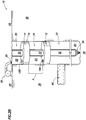
- a method for traversing a leak path comprises a pipe in pipe piston thrust system 10 operating when there is a lateral leak path 80.
- the pump 26 pumps fluid 20 into the first annulus 22 of the wellbore 16 where the tubular string 32 and drill bit 34 are disposed.
- a first piston assembly 12 disposed in the wellbore 16 selectively sealingly engages with the wellbore 16 creating a second annulus 24 between the first piston assembly 12 and the surface 28.
- the first piston assembly 12 comprises a by-pass 18A which allows for selective communication of the fluid 20 between the first annulus 22 and the second annulus 24.
- the by-pass 18A may not be integrated with the first piston assembly 12 and may be located in a fixed position along the wellbore 16. In an embodiment illustrated in Figure 2A , the by-pass 18A is closed so that pump 26 may provide fluid pressure on the first piston assembly 12, thereby applying weight to drive the drill bit 34 through the subterranean formation 36. In an embodiment, the by-pass 18A may be open when additional weight is not needed to drive the drill bit 34 through the subterranean formation 36. In an embodiment, the first piston assembly 12 is fixedly attached to the tubular string 32.
- the first piston assembly 12 may selectively sealingly engaged with the tubular string 32 so that the first piston assembly 12 may move axially along the tubular string and then sealingly engage the tubular string 32 preventing fluid communication between the first annulus 22 and the second annulus 24.
- the selectively sealingly engagement of the first piston assembly 12 to the tubular string 32 may be accomplished by the coupling system previously described.
- the pump 26 may then pump fluid into the second annulus 24 creating pressure on the first piston assembly 12 and applying weight on the drill bit 34.
- a second piston assembly 14 is disposed in the wellbore 16, which may selectively sealingly engage with the wellbore 16 to create a third annulus 30 between the second piston assembly 14 and the surface 28.
- the second piston assembly 14 may be fixedly attached to the tubular string 32 so that as the drill bit 34 and the first piston assembly 12 move axially through the wellbore 16, so does the second piston assembly 14, and the first piston assembly 12 and the second piston assembly 14 may slidingly sealingly engage the wellbore 16. This also allows for the second annulus 24 to maintain an axial distance X along the wellbore 16.
- the second piston assembly 14 comprises a by-pass 18B which allows for selective communication of the fluid 20 between the second annulus 24 and the third annulus 30.
- the by-pass 18B may not be integrated with the second piston assembly 14 and may be located in a fixed position along the wellbore 16. The by-pass 18B may remain open so that fluid 20 can communicate between the third annulus 30 and the second annulus 24, thereby applying pressure to the first piston assembly 12 to drive the drill bit 34.
- the by-pass 18B may remain closed preventing fluid from communicating between the third annulus 30 and the second annulus 24 and thus applying pressure to the second piston assembly 14 to drive the drill bit 34.
- the first piston assembly 12 and the second piston assembly 14 may move axially downstream through the wellbore 16 where the first piston assembly 12 encounters a lateral leak path 80.
- the distance X between the upstream side of the first piston assembly 12 and the downstream side of the second piston assembly 14 may be maintained.
- a sensor 58 may detect the drop in pressure across the first piston assembly 12 due to the lateral leak path 80 and sends a signal to a processor 60 of a control system 56 or sends a signal to an operator located on the surface 28.
- the rate of axial movement which may slow due to the loss of fluid pressure across the first piston assembly 12 may be used to indicate the presence of a leak path 80.
- the by-pass 18A on the first piston assembly 12 is open and the by-pass 18B on the second piston assembly 14 is closed preventing fluid communication between the second annulus 24 and the third annulus 30.
- the output of the pump 26 may also be adjusted. This configuration allows for pressure to be applied on the second piston assembly 14 so that weight may continue to be applied driving the drill bit 34 through the subterranean formation 36.
- one or more subsequent piston assemblies may continue to drive the drill bit 34 through the subterranean formation 36 as each piston assembly 116 moves axially along the wellbore 16 and enters the leak path 80.
- the steps described with respect to Figures 2A-2D may be repeated for each of the one or more subsequent piston assemblies 114.
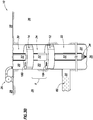
- a method for traversing a lateral break may include using a pipe in pipe piston thrust system 10 operating when there is a lateral break 82.
- the pump 26 pumps fluid 20 into the first annulus 22 of the wellbore 16 where the tubular string 32 and drill bit 34 are disposed.
- a first piston assembly 12 is disposed in the wellbore 16 selectively sealingly engages with the wellbore 16 creating a second annulus 24 between the first piston assembly 12 and the surface 28.
- the first piston assembly 12 comprises a by-pass 18A that allows for selective communication of the fluid between the first annulus 22 and the second annulus 24.
- the by-pass 18A is closed so that pump 26 may provide fluid pressure on the first piston assembly 12, thereby applying weight to drive the drill bit 34 through the subterranean formation 36.
- the first piston assembly 12 is fixedly attached to the tubular string 32.
- a pump 26 then pumps fluid 20 into the second annulus 24 creating pressure on the first piston assembly 12 allowing weight to drive the drill bit 34.
- a second piston assembly 14 may be disposed in the wellbore 16 and selectively sealingly engage with the wellbore 16 creating a third annulus 30 between the second piston assembly 14 and the surface 28.
- the second piston assembly 14 is fixedly attached to the tubular string 32 so that as the drill bit 34 and the first piston assembly 12 move axially through the wellbore 16, so does the second piston assembly 14, and the first piston assembly 12 and the second piston assembly 14 may slidingly sealingly engage the wellbore 16. This also allows for the second annulus 24 to maintain an axial distance X along the wellbore 16.
- the second piston assembly 14 comprises a by-pass 18B which allows for selective communication of the fluid 20 between the second annulus 24 and the third annulus 30.
- the by-pass 18B may not be integrated with the second piston assembly 14 and may be located in a fixed position along the wellbore 16. In this embodiment the by-pass 18B may remain open so that fluid 20 can communicate between the third annulus 30 and the second annulus 24 applying pressure to the first piston assembly 12 to drive the drill bit 34. In other embodiment, the by-pass 18B may remain closed preventing fluid from communicating between the third annulus 30 and the second annulus 24 and thus applying pressure to the second piston assembly 14 to drive the drill bit 34.
- the first piston assembly 12 moving axially down the wellbore 16 may encounter a lateral break 82.
- the lateral break 82 breaks the sealing engagement between the first piston assembly 12 and wellbore 16, but fluid 20 is not permitted to leak into the subterranean formation 36.
- the differential pressure across the first piston assembly 12 may be at least partially lost.
- the fluid pressure created by the pump 26 may no longer be maintained on the first piston assembly 12 to drive the drill bit 34.
- a sensor 58 may detect the drop in pressure across the first piston assembly 12 due to the lateral break 82 and sends a signal to a processor 60 of a control system 56 or sends a signal to an operator located on the surface 28.
- the rate of axial movement which may slow due to the loss of fluid pressure across the first piston assembly 12 may be used to indicate the presence of a leak path 80.
- the by-pass 18A on the first piston assembly 12 may be opened and the by-pass 18B on the second piston assembly 14 may close, thereby preventing fluid communication between the second annulus 24 and the third annulus 30.
- the control system 56 may also command the pump to adjust the flow of fluid 20. This configuration allows for pressure to be applied on the second piston assembly 14 so that weight may continue to be applied driving the drill bit 34 through the subterranean formation 36.
- FIG. 3D once the first piston assembly 116A moves past the lateral break 82, the first piston assembly 116A sealing engages with the wellbore 16 again.
- a sensor 58 on the first piston assembly 116A may detect the sealing engagement with first piston assembly 12 and the wellbore 16 and send a signal to the processor 60 of the control system 56.
- the processor 60 then commands the by-pass 18A of the first piston assembly 116A to close.
- the control system 56 may also command the pump 26 to adjust the flow of fluid 20.
- the control system 56 or an operator at the surface 28 may then command the by-pass 18B of the second pistons assembly 14 to open to apply weight to the first piston assembly 12 which is closest to the drill bit 34.
- Figure 3D depicts additional piston 114.
- Additional piston 114 may be axially disposed in the wellbore after pistons 116A and 116B have traversed through the wellbore 16. Additional piston 114, may be used to drive the piston if, for example, there is leak path further downstream of pistons 116A and 116B so that additional piston 114 may continue to apply weight to the drill bit 34 when pistons 116A and 116B enter the leak path zone.
- an embodiment depicts stack 150 comprising the first piston assembly 12 engaged with the second piston assembly 14 wherein the second annulus 24 is closed so that the stack 150 creates a bridge over the lateral break 82 so that a seal is maintained between the stack 150 and the wellbore 16 as the stack 150 crosses the lateral break 82.
- the first piston assembly 12 and the second piston assembly 14 comprising the stack 150 is fixedly attached to the tubular string 32.
- the first piston assembly 12 and second piston assembly 14 may move axially and independently along the tubular string 32 and engage to form the stack 150 to maintain a sealing engagement with the wellbore 16 across the lateral break 82.
- the stack 150 may selectively grippingly engage with the tubular string 32.
- the first piston assembly 12 and the second piston assembly 14 may engage each other using a coupling system (not shown) or in an embodiment with the pressure exerted from the second piston assembly 14 on to the first piston assembly 12.
- the stack 150 may selectively grippingly engage with the tubular string 32 by a coupling system (not shown) such as latching and de-latching mechanisms where the coupling systems receives a signal to couple or decouple a piston assembly with the tubular string 32.
- the latching system may allow the piston assembly to couple or decouple anywhere along the axis of the tubular string 32 or there may be pre-selected points along the axis of the tubular string 32 where a piston assembly my couple or decouple with the tubular spring 32.
- an uncased section of the wellbore 16 can have a larger diameter as compared to the cased section of the wellbore 16.
- the diameters of the first piston assembly 12 and the second piston assembly 14 can be actuated to increase or reduce in order to accommodate the larger diameter of the wellbore 16.
- actuators 202 and 204 can be operated to inwardly retract the respective gripping devices 206 and sealing devices 208 so that the diameters of the first piston assembly 12 are less than the diameter of the second piston assembly 14.
- Actuators 202 and 204 can also be operated expand the respective gripping devices 206 and sealing devices 208 so that the diameters of the piston assemblies may increase. This may be useful when piston assembly moves between cased and uncased wellbores 16.
- the diameters of the first piston assembly 12 and the second piston assembly 14 may be controlled by the control system 56 of Figure 1D . Alternatively, the first piston assembly 12 and the second piston assembly 14 may be decoupled from the tubular and left to float at the edge.
- R Rl+k ⁇ (Ru-Rl), wherein k is a variable ranging from 1 percent to 100 percent with a 1 percent increment, i.e., k is 1 percent, 2 percent, 3 percent, 4 percent, 5 percent, ..., 50 percent, 51 percent, 52 percent, ..., 95 percent, 96 percent, 97 percent, 98 percent, 99 percent, or 100 percent.
- R Rl+k ⁇ (Ru-Rl)
- k is a variable ranging from 1 percent to 100 percent with a 1 percent increment, i.e., k is 1 percent, 2 percent, 3 percent, 4 percent, 5 percent, ..., 50 percent, 51 percent, 52 percent, ..., 95 percent, 96 percent, 97 percent, 98 percent, 99 percent, or 100 percent.
- any numerical range defined by two R numbers as defined in the above is also specifically disclosed.
Landscapes
- Engineering & Computer Science (AREA)
- Geology (AREA)
- Life Sciences & Earth Sciences (AREA)
- Mining & Mineral Resources (AREA)
- Environmental & Geological Engineering (AREA)
- Fluid Mechanics (AREA)
- Physics & Mathematics (AREA)
- General Life Sciences & Earth Sciences (AREA)
- Geochemistry & Mineralogy (AREA)
- Mechanical Engineering (AREA)
- Earth Drilling (AREA)
- Reciprocating Pumps (AREA)
- Details Of Reciprocating Pumps (AREA)
Claims (20)
- Système de poussée à piston de tube dans tube comprenant :une pluralité d'ensembles de piston (12, 14) configurés pour entrer en contact de manière étanche avec un puits de forage (16) ;une pompe (26) configurée pour transférer un fluide (20) dans le puits de forage ; etune dérivation (18A, 18B) disposée entre une pluralité d'anneaux (22, 24, 30) formés par la pluralité d'ensembles de piston, dans lequel la dérivation permet une communication sélective du fluide entre la pluralité d'anneaux et permet la création sélective de pressions différentielles à travers la pluralité d'ensembles de piston.
- Système selon la revendication 1, comprenant en outre une colonne tubulaire (32).
- Système selon la revendication 1 ou 2, comprenant en outre un système de commande (56), dans lequel le système de commande comprend une pluralité de capteurs (58) et un processeur (60), dans lequel la pluralité de capteurs envoient au moins un signal au processeur, dans lequel le processeur reçoit au moins un signal et envoie au moins un signal.
- Système selon la revendication 2, comprenant en outre un mécanisme de couplage configuré pour faire entrer en contact par accrochage de manière sélective la pluralité d'ensembles de piston (12, 14) avec la colonne tubulaire.
- Système selon une quelconque revendication précédente, dans lequel la pluralité d'ensembles de piston (12, 14) a une pluralité de diamètres configurés pour s'adapter au diamètre intérieur du puits de forage.
- Système selon la revendication 2, dans lequel la colonne tubulaire comprend un anneau de colonne tubulaire (22, 24, 30) .
- Système selon la revendication 2, dans lequel la colonne tubulaire comprend un chemin électrique configuré pour conduire de l'électricité et configuré pour fournir de l'énergie électrique à au moins l'un de la pluralité d'ensembles de piston et à au moins une dérivation.
- Système selon la revendication 2, 4 ou 6, dans lequel la pluralité de capteurs (58) est configurée pour fournir au moins un signal par l'intermédiaire de la colonne tubulaire et le processeur est configuré pour fournir au moins un signal par l'intermédiaire de la colonne tubulaire.
- Système selon la revendication 8, dans lequel au moins un signal est transféré sans fil, moyennant quoi au moins un signal est fourni par la pluralité de capteurs et au moins un signal est fourni par le processeur.
- Système selon la revendication 3, dans lequel le système de commande est configuré pour faire fonctionner automatiquement la pompe en réponse à un paramètre d'opération de forage détecté.
- Procédé pour traverser un chemin de fuite comprenant :la fermeture d'une première dérivation (18A) par l'intermédiaire d'un premier ensemble de piston (12), dans lequel le premier ensemble de piston est disposé dans un puits de forage (16) et entre en contact de manière étanche avec le puits de forage ;l'ouverture d'une deuxième dérivation (18B) par l'intermédiaire d'un deuxième ensemble de piston (14) pour établir une communication fluidique avec le premier ensemble de piston, dans lequel le deuxième ensemble de piston est disposé dans le puits de forage et entre en contact de manière étanche avec le puits de forage ;le déplacement axial du premier ensemble de piston et du deuxième ensemble de piston dans une première direction dans un puits de forage en augmentant la pression à travers le premier ensemble de piston ;la fermeture de la deuxième dérivation par l'intermédiaire du deuxième ensemble de piston ;la fourniture d'un différentiel de pression à travers le deuxième ensemble de piston ; etle déplacement axial du premier ensemble de piston dans la première direction au-delà d'un chemin latéral sur la base du différentiel de pression à travers le deuxième ensemble de piston.
- Procédé selon la revendication 11, dans lequel le premier ensemble de piston (12) est en aval du deuxième ensemble de piston (14).
- Procédé selon la revendication 11 ou 12, comprenant en outre :la fermeture de la deuxième dérivation (18B) par l'intermédiaire du deuxième ensemble de piston ;l'ouverture d'une troisième dérivation par l'intermédiaire d'un troisième ensemble de piston pour établir une communication fluidique avec les premier et deuxième ensembles de piston ;la fourniture d'un différentiel de pression sur le deuxième ensemble de piston ;le déplacement axial du premier ensemble de piston, du deuxième ensemble de piston et du troisième ensemble de piston dans la première direction dans le puits de forage sur la base du différentiel de pression à travers le deuxième ensemble de piston ;la fermeture de la troisième dérivation par l'intermédiaire du troisième ensemble de piston ;la fourniture d'un différentiel de pression à travers le troisième ensemble de piston ; etle déplacement axial du premier ensemble de piston et du deuxième ensemble de piston dans la première direction au-delà d'un chemin latéral sur la base du différentiel de pression à travers le troisième ensemble de piston.
- Procédé selon la revendication 13, dans lequel le deuxième ensemble de piston (14) est en aval du troisième ensemble de piston.
- Procédé selon la revendication 11, 12 ou 14, comprenant en outre :la fermeture d'une dérivation par l'intermédiaire d'au moins un ensemble de piston précédent ;l'ouverture d'une dérivation par l'intermédiaire d'un ensemble de piston suivant pour établir une communication fluidique avec au moins l'un des ensembles de piston précédents ;la fourniture d'un différentiel de pression à travers l'ensemble de piston suivant ;le déplacement axial de l'ensemble de piston suivant et de l'au moins un ensemble précédent dans une première direction dans un puits de forage sur la base du différentiel de pression à travers l'ensemble de piston suivant ;la fermeture d'une dérivation par l'intermédiaire de l'ensemble de piston suivant ;la fourniture d'un différentiel de pression à travers l'ensemble de piston suivant ; etle déplacement axial des ensembles de piston précédents et de l'ensemble de piston suivant dans la première direction en traversant un chemin latéral sur la base du différentiel de pression à travers l'ensemble de piston suivant.
- Procédé selon la revendication 15, dans lequel chaque ensemble de piston suivant est en amont des ensembles de piston précédents.
- Procédé selon la revendication 11, comprenant en outre :
l'ouverture de la première dérivation (18A) à travers le premier ensemble de piston (12) lorsque la pression diminue à travers le premier ensemble de piston. - Procédé selon la revendication 17, dans lequel le premier ensemble de piston (12) est en aval du deuxième ensemble de piston (14).
- Procédé selon la revendication 17 ou 18, dans lequel la diminution de la pression à travers le premier ensemble de piston comprend le déplacement du premier ensemble de piston à travers une rupture latérale (82).
- Procédé selon la revendication 17, 18 ou 19, dans lequel le procédé comprend en outre :le déplacement du premier ensemble de piston (12) et du deuxième ensemble de piston (14) axialement le long du puits de forage dans la première direction en maintenant le premier anneau ; etl'augmentation de la pression à travers le premier ensemble de piston, dans lequel l'augmentation de la pression à travers le premier ensemble de piston comprend :la mise en contact de manière étanche du premier ensemble de piston avec le puits de forage ;l'ouverture de la dérivation (18B) à travers le deuxième ensemble de piston ; etla fermeture de la dérivation (18A) à travers le premier ensemble de piston.
Applications Claiming Priority (1)
| Application Number | Priority Date | Filing Date | Title |
|---|---|---|---|
| PCT/US2012/046812 WO2014011193A1 (fr) | 2012-07-13 | 2012-07-13 | Système de poussée à piston de tube dans tube |
Publications (3)
| Publication Number | Publication Date |
|---|---|
| EP2872726A1 EP2872726A1 (fr) | 2015-05-20 |
| EP2872726A4 EP2872726A4 (fr) | 2016-08-17 |
| EP2872726B1 true EP2872726B1 (fr) | 2019-06-12 |
Family
ID=49912968
Family Applications (1)
| Application Number | Title | Priority Date | Filing Date |
|---|---|---|---|
| EP12881023.1A Not-in-force EP2872726B1 (fr) | 2012-07-13 | 2012-07-13 | Système de poussée à piston de tube dans tube |
Country Status (9)
| Country | Link |
|---|---|
| US (2) | US8757279B2 (fr) |
| EP (1) | EP2872726B1 (fr) |
| AU (2) | AU2012384932B2 (fr) |
| BR (1) | BR112015000802A2 (fr) |
| CA (1) | CA2879085C (fr) |
| EA (1) | EA027612B1 (fr) |
| MX (1) | MX358962B (fr) |
| SG (1) | SG11201500099QA (fr) |
| WO (1) | WO2014011193A1 (fr) |
Families Citing this family (3)
| Publication number | Priority date | Publication date | Assignee | Title |
|---|---|---|---|---|
| US8757279B2 (en) | 2012-07-13 | 2014-06-24 | Halliburton Energy Services, Inc. | Pipe in pipe piston thrust system |
| US9264667B1 (en) | 2014-08-15 | 2016-02-16 | Bank Of America Corporation | Determining electronic media format when transferring a customer between specialists or amongst communication sources at a customer service outlet |
| CN113090210B (zh) * | 2021-04-07 | 2022-09-02 | 中国石油大学(华东) | 一种变径推送短接装置 |
Citations (1)
| Publication number | Priority date | Publication date | Assignee | Title |
|---|---|---|---|---|
| US5060737A (en) * | 1986-07-01 | 1991-10-29 | Framo Developments (Uk) Limited | Drilling system |
Family Cites Families (15)
| Publication number | Priority date | Publication date | Assignee | Title |
|---|---|---|---|---|
| US3957119A (en) | 1974-12-18 | 1976-05-18 | Yonker John H | Pump down method |
| US4756364A (en) * | 1986-12-10 | 1988-07-12 | Halliburton Company | Packer bypass |
| US4962815A (en) * | 1989-07-17 | 1990-10-16 | Halliburton Company | Inflatable straddle packer |
| US5209304A (en) | 1991-08-16 | 1993-05-11 | Western Atlas International, Inc. | Propulsion apparatus for positioning selected tools in tubular members |
| US7836950B2 (en) * | 1994-10-14 | 2010-11-23 | Weatherford/Lamb, Inc. | Methods and apparatus to convey electrical pumping systems into wellbores to complete oil and gas wells |
| BR9610373A (pt) * | 1995-08-22 | 1999-12-21 | Western Well Toll Inc | Ferramenta de furo de tração-empuxo |
| US8164339B2 (en) * | 2008-06-09 | 2012-04-24 | Baker Hughes Incorporated | Apparatus and system for geosteering and formation evaluation utilizing improved antennas |
| NO333210B1 (no) | 2008-10-01 | 2013-04-08 | Reelwell As | Nedihullsventilanordning |
| NO333203B1 (no) | 2008-10-01 | 2013-04-08 | Reelwell As | Verktoyenhet for nedihulls bruk |
| NO331312B3 (no) | 2009-02-17 | 2014-04-22 | Reelwell As | Tetningssystem mellom relativt roterende elementer og fremgangsmåte for operasjon av slikt tetningssystem. |
| NO332488B1 (no) | 2009-04-17 | 2012-10-01 | Reelwell As | Nedihulls pakningstetning |
| IES20090407A2 (en) * | 2009-05-26 | 2009-10-28 | Espen Alhaug | Method and system for transferring signals through a drill pipe system |
| NO332920B1 (no) | 2009-07-06 | 2013-02-04 | Reelwell As | Et nedihulls bronnverktoy tilveiebrakt med et stempel |
| WO2011140426A1 (fr) * | 2010-05-06 | 2011-11-10 | Smart Drilling And Completion, Inc. | Système de forage et de complétion universel |
| US8757279B2 (en) | 2012-07-13 | 2014-06-24 | Halliburton Energy Services, Inc. | Pipe in pipe piston thrust system |
-
2012
- 2012-07-13 US US13/988,303 patent/US8757279B2/en active Active
- 2012-07-13 EP EP12881023.1A patent/EP2872726B1/fr not_active Not-in-force
- 2012-07-13 AU AU2012384932A patent/AU2012384932B2/en not_active Ceased
- 2012-07-13 MX MX2015000306A patent/MX358962B/es active IP Right Grant
- 2012-07-13 BR BR112015000802A patent/BR112015000802A2/pt not_active Application Discontinuation
- 2012-07-13 SG SG11201500099QA patent/SG11201500099QA/en unknown
- 2012-07-13 CA CA2879085A patent/CA2879085C/fr active Active
- 2012-07-13 WO PCT/US2012/046812 patent/WO2014011193A1/fr active Application Filing
- 2012-07-13 EA EA201590214A patent/EA027612B1/ru not_active IP Right Cessation
-
2013
- 2013-12-17 US US14/109,537 patent/US9670748B2/en active Active
-
2016
- 2016-03-17 AU AU2016201710A patent/AU2016201710B2/en not_active Ceased
Patent Citations (1)
| Publication number | Priority date | Publication date | Assignee | Title |
|---|---|---|---|---|
| US5060737A (en) * | 1986-07-01 | 1991-10-29 | Framo Developments (Uk) Limited | Drilling system |
Also Published As
| Publication number | Publication date |
|---|---|
| EA027612B1 (ru) | 2017-08-31 |
| AU2012384932B2 (en) | 2016-04-14 |
| AU2016201710A1 (en) | 2016-04-07 |
| US20140102690A1 (en) | 2014-04-17 |
| EP2872726A4 (fr) | 2016-08-17 |
| EP2872726A1 (fr) | 2015-05-20 |
| AU2016201710B2 (en) | 2017-04-13 |
| BR112015000802A2 (pt) | 2017-06-27 |
| WO2014011193A1 (fr) | 2014-01-16 |
| SG11201500099QA (en) | 2015-02-27 |
| AU2012384932A1 (en) | 2015-02-26 |
| MX358962B (es) | 2018-09-11 |
| US20140014372A1 (en) | 2014-01-16 |
| CA2879085A1 (fr) | 2014-01-16 |
| EA201590214A1 (ru) | 2015-04-30 |
| CA2879085C (fr) | 2017-04-11 |
| US9670748B2 (en) | 2017-06-06 |
| MX2015000306A (es) | 2015-10-29 |
| US8757279B2 (en) | 2014-06-24 |
Similar Documents
| Publication | Publication Date | Title |
|---|---|---|
| EP3161249B1 (fr) | Système de puits multilatéral | |
| EP2195506B1 (fr) | Système de forage à ensemble de fond de puits double | |
| EP2691595B1 (fr) | Mise en place d'une colonne perdue à usage unique et assemblage pour le forage | |
| EP3186466B1 (fr) | Forage directionnel lors du transport d'un élément de chemisage comportant des capacités de stationnement de verrouillage pour des trajets multiples | |
| AU2016201710B2 (en) | Pipe in pipe piston thrust system | |
| EP3339563B1 (fr) | Barrière contre les dépôts pour outils de débranchement hydrauliques | |
| CN105992860B (zh) | 用于井下套管磨铣系统的控制系统 | |
| EP2964873B1 (fr) | Portion de tube spiralé assistée par câble et procédé pour opération d'une telle portion de tube spiralé | |
| EP2447465B1 (fr) | Système et procédé pour ouvrir une fenêtre dans un fil de boîtier pour une construction multilatérale de puits de forage | |
| US9388663B2 (en) | Downhole circulating valve having a metal-to-metal seal and method for operating same | |
| US11913298B2 (en) | Downhole milling system | |
| US8770300B2 (en) | Debris barrier for hydraulic disconnect tools | |
| US8763707B2 (en) | Downhole circulating valve having a metal-to-metal seal |
Legal Events
| Date | Code | Title | Description |
|---|---|---|---|
| PUAI | Public reference made under article 153(3) epc to a published international application that has entered the european phase |
Free format text: ORIGINAL CODE: 0009012 |
|
| 17P | Request for examination filed |
Effective date: 20150108 |
|
| AK | Designated contracting states |
Kind code of ref document: A1 Designated state(s): AL AT BE BG CH CY CZ DE DK EE ES FI FR GB GR HR HU IE IS IT LI LT LU LV MC MK MT NL NO PL PT RO RS SE SI SK SM TR |
|
| AX | Request for extension of the european patent |
Extension state: BA ME |
|
| DAX | Request for extension of the european patent (deleted) | ||
| RIC1 | Information provided on ipc code assigned before grant |
Ipc: E21B 23/08 20060101AFI20160219BHEP Ipc: E21B 33/124 20060101ALI20160219BHEP Ipc: E21B 4/18 20060101ALI20160219BHEP |
|
| REG | Reference to a national code |
Ref country code: DE Ref legal event code: R079 Ref document number: 602012061042 Country of ref document: DE Free format text: PREVIOUS MAIN CLASS: E21B0019240000 Ipc: E21B0023080000 |
|
| RA4 | Supplementary search report drawn up and despatched (corrected) |
Effective date: 20160719 |
|
| RIC1 | Information provided on ipc code assigned before grant |
Ipc: E21B 23/08 20060101AFI20160713BHEP Ipc: E21B 4/18 20060101ALI20160713BHEP Ipc: E21B 33/124 20060101ALI20160713BHEP |
|
| STAA | Information on the status of an ep patent application or granted ep patent |
Free format text: STATUS: EXAMINATION IS IN PROGRESS |
|
| 17Q | First examination report despatched |
Effective date: 20180725 |
|
| GRAP | Despatch of communication of intention to grant a patent |
Free format text: ORIGINAL CODE: EPIDOSNIGR1 |
|
| STAA | Information on the status of an ep patent application or granted ep patent |
Free format text: STATUS: GRANT OF PATENT IS INTENDED |
|
| INTG | Intention to grant announced |
Effective date: 20190130 |
|
| GRAS | Grant fee paid |
Free format text: ORIGINAL CODE: EPIDOSNIGR3 |
|
| GRAA | (expected) grant |
Free format text: ORIGINAL CODE: 0009210 |
|
| STAA | Information on the status of an ep patent application or granted ep patent |
Free format text: STATUS: THE PATENT HAS BEEN GRANTED |
|
| AK | Designated contracting states |
Kind code of ref document: B1 Designated state(s): AL AT BE BG CH CY CZ DE DK EE ES FI FR GB GR HR HU IE IS IT LI LT LU LV MC MK MT NL NO PL PT RO RS SE SI SK SM TR |
|
| REG | Reference to a national code |
Ref country code: GB Ref legal event code: FG4D |
|
| REG | Reference to a national code |
Ref country code: CH Ref legal event code: EP |
|
| REG | Reference to a national code |
Ref country code: AT Ref legal event code: REF Ref document number: 1142760 Country of ref document: AT Kind code of ref document: T Effective date: 20190615 |
|
| REG | Reference to a national code |
Ref country code: DE Ref legal event code: R096 Ref document number: 602012061042 Country of ref document: DE |
|
| REG | Reference to a national code |
Ref country code: IE Ref legal event code: FG4D |
|
| REG | Reference to a national code |
Ref country code: NO Ref legal event code: T2 Effective date: 20190612 |
|
| REG | Reference to a national code |
Ref country code: NL Ref legal event code: MP Effective date: 20190612 |
|
| REG | Reference to a national code |
Ref country code: LT Ref legal event code: MG4D |
|
| PG25 | Lapsed in a contracting state [announced via postgrant information from national office to epo] |
Ref country code: HR Free format text: LAPSE BECAUSE OF FAILURE TO SUBMIT A TRANSLATION OF THE DESCRIPTION OR TO PAY THE FEE WITHIN THE PRESCRIBED TIME-LIMIT Effective date: 20190612 Ref country code: LT Free format text: LAPSE BECAUSE OF FAILURE TO SUBMIT A TRANSLATION OF THE DESCRIPTION OR TO PAY THE FEE WITHIN THE PRESCRIBED TIME-LIMIT Effective date: 20190612 Ref country code: FI Free format text: LAPSE BECAUSE OF FAILURE TO SUBMIT A TRANSLATION OF THE DESCRIPTION OR TO PAY THE FEE WITHIN THE PRESCRIBED TIME-LIMIT Effective date: 20190612 Ref country code: AL Free format text: LAPSE BECAUSE OF FAILURE TO SUBMIT A TRANSLATION OF THE DESCRIPTION OR TO PAY THE FEE WITHIN THE PRESCRIBED TIME-LIMIT Effective date: 20190612 Ref country code: SE Free format text: LAPSE BECAUSE OF FAILURE TO SUBMIT A TRANSLATION OF THE DESCRIPTION OR TO PAY THE FEE WITHIN THE PRESCRIBED TIME-LIMIT Effective date: 20190612 |
|
| PG25 | Lapsed in a contracting state [announced via postgrant information from national office to epo] |
Ref country code: LV Free format text: LAPSE BECAUSE OF FAILURE TO SUBMIT A TRANSLATION OF THE DESCRIPTION OR TO PAY THE FEE WITHIN THE PRESCRIBED TIME-LIMIT Effective date: 20190612 Ref country code: BG Free format text: LAPSE BECAUSE OF FAILURE TO SUBMIT A TRANSLATION OF THE DESCRIPTION OR TO PAY THE FEE WITHIN THE PRESCRIBED TIME-LIMIT Effective date: 20190912 Ref country code: GR Free format text: LAPSE BECAUSE OF FAILURE TO SUBMIT A TRANSLATION OF THE DESCRIPTION OR TO PAY THE FEE WITHIN THE PRESCRIBED TIME-LIMIT Effective date: 20190913 Ref country code: RS Free format text: LAPSE BECAUSE OF FAILURE TO SUBMIT A TRANSLATION OF THE DESCRIPTION OR TO PAY THE FEE WITHIN THE PRESCRIBED TIME-LIMIT Effective date: 20190612 |
|
| REG | Reference to a national code |
Ref country code: AT Ref legal event code: MK05 Ref document number: 1142760 Country of ref document: AT Kind code of ref document: T Effective date: 20190612 |
|
| PG25 | Lapsed in a contracting state [announced via postgrant information from national office to epo] |
Ref country code: PT Free format text: LAPSE BECAUSE OF FAILURE TO SUBMIT A TRANSLATION OF THE DESCRIPTION OR TO PAY THE FEE WITHIN THE PRESCRIBED TIME-LIMIT Effective date: 20191014 Ref country code: RO Free format text: LAPSE BECAUSE OF FAILURE TO SUBMIT A TRANSLATION OF THE DESCRIPTION OR TO PAY THE FEE WITHIN THE PRESCRIBED TIME-LIMIT Effective date: 20190612 Ref country code: CZ Free format text: LAPSE BECAUSE OF FAILURE TO SUBMIT A TRANSLATION OF THE DESCRIPTION OR TO PAY THE FEE WITHIN THE PRESCRIBED TIME-LIMIT Effective date: 20190612 Ref country code: NL Free format text: LAPSE BECAUSE OF FAILURE TO SUBMIT A TRANSLATION OF THE DESCRIPTION OR TO PAY THE FEE WITHIN THE PRESCRIBED TIME-LIMIT Effective date: 20190612 Ref country code: EE Free format text: LAPSE BECAUSE OF FAILURE TO SUBMIT A TRANSLATION OF THE DESCRIPTION OR TO PAY THE FEE WITHIN THE PRESCRIBED TIME-LIMIT Effective date: 20190612 Ref country code: AT Free format text: LAPSE BECAUSE OF FAILURE TO SUBMIT A TRANSLATION OF THE DESCRIPTION OR TO PAY THE FEE WITHIN THE PRESCRIBED TIME-LIMIT Effective date: 20190612 Ref country code: SK Free format text: LAPSE BECAUSE OF FAILURE TO SUBMIT A TRANSLATION OF THE DESCRIPTION OR TO PAY THE FEE WITHIN THE PRESCRIBED TIME-LIMIT Effective date: 20190612 |
|
| REG | Reference to a national code |
Ref country code: DE Ref legal event code: R119 Ref document number: 602012061042 Country of ref document: DE |
|
| PG25 | Lapsed in a contracting state [announced via postgrant information from national office to epo] |
Ref country code: ES Free format text: LAPSE BECAUSE OF FAILURE TO SUBMIT A TRANSLATION OF THE DESCRIPTION OR TO PAY THE FEE WITHIN THE PRESCRIBED TIME-LIMIT Effective date: 20190612 Ref country code: IT Free format text: LAPSE BECAUSE OF FAILURE TO SUBMIT A TRANSLATION OF THE DESCRIPTION OR TO PAY THE FEE WITHIN THE PRESCRIBED TIME-LIMIT Effective date: 20190612 Ref country code: IS Free format text: LAPSE BECAUSE OF FAILURE TO SUBMIT A TRANSLATION OF THE DESCRIPTION OR TO PAY THE FEE WITHIN THE PRESCRIBED TIME-LIMIT Effective date: 20191012 Ref country code: SM Free format text: LAPSE BECAUSE OF FAILURE TO SUBMIT A TRANSLATION OF THE DESCRIPTION OR TO PAY THE FEE WITHIN THE PRESCRIBED TIME-LIMIT Effective date: 20190612 |
|
| REG | Reference to a national code |
Ref country code: CH Ref legal event code: PL |
|
| PG25 | Lapsed in a contracting state [announced via postgrant information from national office to epo] |
Ref country code: MC Free format text: LAPSE BECAUSE OF FAILURE TO SUBMIT A TRANSLATION OF THE DESCRIPTION OR TO PAY THE FEE WITHIN THE PRESCRIBED TIME-LIMIT Effective date: 20190612 Ref country code: TR Free format text: LAPSE BECAUSE OF FAILURE TO SUBMIT A TRANSLATION OF THE DESCRIPTION OR TO PAY THE FEE WITHIN THE PRESCRIBED TIME-LIMIT Effective date: 20190612 |
|
| REG | Reference to a national code |
Ref country code: BE Ref legal event code: MM Effective date: 20190731 |
|
| PLBE | No opposition filed within time limit |
Free format text: ORIGINAL CODE: 0009261 |
|
| STAA | Information on the status of an ep patent application or granted ep patent |
Free format text: STATUS: NO OPPOSITION FILED WITHIN TIME LIMIT |
|
| PG25 | Lapsed in a contracting state [announced via postgrant information from national office to epo] |
Ref country code: DK Free format text: LAPSE BECAUSE OF FAILURE TO SUBMIT A TRANSLATION OF THE DESCRIPTION OR TO PAY THE FEE WITHIN THE PRESCRIBED TIME-LIMIT Effective date: 20190612 Ref country code: PL Free format text: LAPSE BECAUSE OF FAILURE TO SUBMIT A TRANSLATION OF THE DESCRIPTION OR TO PAY THE FEE WITHIN THE PRESCRIBED TIME-LIMIT Effective date: 20190612 Ref country code: DE Free format text: LAPSE BECAUSE OF NON-PAYMENT OF DUE FEES Effective date: 20200201 |
|
| 26N | No opposition filed |
Effective date: 20200313 |
|
| PG25 | Lapsed in a contracting state [announced via postgrant information from national office to epo] |
Ref country code: SI Free format text: LAPSE BECAUSE OF FAILURE TO SUBMIT A TRANSLATION OF THE DESCRIPTION OR TO PAY THE FEE WITHIN THE PRESCRIBED TIME-LIMIT Effective date: 20190612 Ref country code: BE Free format text: LAPSE BECAUSE OF NON-PAYMENT OF DUE FEES Effective date: 20190731 Ref country code: LU Free format text: LAPSE BECAUSE OF NON-PAYMENT OF DUE FEES Effective date: 20190713 Ref country code: IS Free format text: LAPSE BECAUSE OF FAILURE TO SUBMIT A TRANSLATION OF THE DESCRIPTION OR TO PAY THE FEE WITHIN THE PRESCRIBED TIME-LIMIT Effective date: 20200224 Ref country code: LI Free format text: LAPSE BECAUSE OF NON-PAYMENT OF DUE FEES Effective date: 20190731 Ref country code: CH Free format text: LAPSE BECAUSE OF NON-PAYMENT OF DUE FEES Effective date: 20190731 |
|
| PG2D | Information on lapse in contracting state deleted |
Ref country code: IS |
|
| PG25 | Lapsed in a contracting state [announced via postgrant information from national office to epo] |
Ref country code: FR Free format text: LAPSE BECAUSE OF NON-PAYMENT OF DUE FEES Effective date: 20190812 Ref country code: IE Free format text: LAPSE BECAUSE OF NON-PAYMENT OF DUE FEES Effective date: 20190713 |
|
| PG25 | Lapsed in a contracting state [announced via postgrant information from national office to epo] |
Ref country code: CY Free format text: LAPSE BECAUSE OF FAILURE TO SUBMIT A TRANSLATION OF THE DESCRIPTION OR TO PAY THE FEE WITHIN THE PRESCRIBED TIME-LIMIT Effective date: 20190612 |
|
| PG25 | Lapsed in a contracting state [announced via postgrant information from national office to epo] |
Ref country code: HU Free format text: LAPSE BECAUSE OF FAILURE TO SUBMIT A TRANSLATION OF THE DESCRIPTION OR TO PAY THE FEE WITHIN THE PRESCRIBED TIME-LIMIT; INVALID AB INITIO Effective date: 20120713 Ref country code: MT Free format text: LAPSE BECAUSE OF FAILURE TO SUBMIT A TRANSLATION OF THE DESCRIPTION OR TO PAY THE FEE WITHIN THE PRESCRIBED TIME-LIMIT Effective date: 20190612 |
|
| PG25 | Lapsed in a contracting state [announced via postgrant information from national office to epo] |
Ref country code: MK Free format text: LAPSE BECAUSE OF FAILURE TO SUBMIT A TRANSLATION OF THE DESCRIPTION OR TO PAY THE FEE WITHIN THE PRESCRIBED TIME-LIMIT Effective date: 20190612 |
|
| PGFP | Annual fee paid to national office [announced via postgrant information from national office to epo] |
Ref country code: NO Payment date: 20220623 Year of fee payment: 11 Ref country code: GB Payment date: 20220506 Year of fee payment: 11 |
|
| REG | Reference to a national code |
Ref country code: NO Ref legal event code: MMEP |
|
| GBPC | Gb: european patent ceased through non-payment of renewal fee |
Effective date: 20230713 |
|
| PG25 | Lapsed in a contracting state [announced via postgrant information from national office to epo] |
Ref country code: GB Free format text: LAPSE BECAUSE OF NON-PAYMENT OF DUE FEES Effective date: 20230713 |