EP2871497A1 - Method for marking a measurement point in a cast concrete ceiling and apparatus for signaling a measurement point - Google Patents
Method for marking a measurement point in a cast concrete ceiling and apparatus for signaling a measurement point Download PDFInfo
- Publication number
- EP2871497A1 EP2871497A1 EP20140191485 EP14191485A EP2871497A1 EP 2871497 A1 EP2871497 A1 EP 2871497A1 EP 20140191485 EP20140191485 EP 20140191485 EP 14191485 A EP14191485 A EP 14191485A EP 2871497 A1 EP2871497 A1 EP 2871497A1
- Authority
- EP
- European Patent Office
- Prior art keywords
- marking
- ring
- locating
- plaster layer
- formwork
- Prior art date
- Legal status (The legal status is an assumption and is not a legal conclusion. Google has not performed a legal analysis and makes no representation as to the accuracy of the status listed.)
- Granted
Links
- 238000000034 method Methods 0.000 title claims abstract description 8
- 238000005259 measurement Methods 0.000 title description 3
- 230000011664 signaling Effects 0.000 title 1
- 239000011505 plaster Substances 0.000 claims abstract description 32
- 230000005291 magnetic effect Effects 0.000 claims abstract description 24
- 238000009415 formwork Methods 0.000 claims abstract description 17
- 230000005294 ferromagnetic effect Effects 0.000 claims abstract description 11
- 239000003302 ferromagnetic material Substances 0.000 claims abstract description 6
- 239000000696 magnetic material Substances 0.000 claims abstract description 6
- 239000003550 marker Substances 0.000 description 9
- 238000004378 air conditioning Methods 0.000 description 2
- 238000005266 casting Methods 0.000 description 1
- 238000005260 corrosion Methods 0.000 description 1
- 230000007797 corrosion Effects 0.000 description 1
- 230000032798 delamination Effects 0.000 description 1
- 238000006073 displacement reaction Methods 0.000 description 1
- 238000005553 drilling Methods 0.000 description 1
- JEIPFZHSYJVQDO-UHFFFAOYSA-N iron(III) oxide Inorganic materials O=[Fe]O[Fe]=O JEIPFZHSYJVQDO-UHFFFAOYSA-N 0.000 description 1
- 230000010287 polarization Effects 0.000 description 1
- 230000036316 preload Effects 0.000 description 1
- 230000002787 reinforcement Effects 0.000 description 1
- 125000006850 spacer group Chemical group 0.000 description 1
Images

Classifications
-
- E—FIXED CONSTRUCTIONS
- E04—BUILDING
- E04G—SCAFFOLDING; FORMS; SHUTTERING; BUILDING IMPLEMENTS OR AIDS, OR THEIR USE; HANDLING BUILDING MATERIALS ON THE SITE; REPAIRING, BREAKING-UP OR OTHER WORK ON EXISTING BUILDINGS
- E04G15/00—Forms or shutterings for making openings, cavities, slits, or channels
- E04G15/06—Forms or shutterings for making openings, cavities, slits, or channels for cavities or channels in walls of floors, e.g. for making chimneys
- E04G15/061—Non-reusable forms
-
- G—PHYSICS
- G01—MEASURING; TESTING
- G01V—GEOPHYSICS; GRAVITATIONAL MEASUREMENTS; DETECTING MASSES OR OBJECTS; TAGS
- G01V3/00—Electric or magnetic prospecting or detecting; Measuring magnetic field characteristics of the earth, e.g. declination, deviation
- G01V3/08—Electric or magnetic prospecting or detecting; Measuring magnetic field characteristics of the earth, e.g. declination, deviation operating with magnetic or electric fields produced or modified by objects or geological structures or by detecting devices
- G01V3/081—Electric or magnetic prospecting or detecting; Measuring magnetic field characteristics of the earth, e.g. declination, deviation operating with magnetic or electric fields produced or modified by objects or geological structures or by detecting devices the magnetic field is produced by the objects or geological structures
-
- B—PERFORMING OPERATIONS; TRANSPORTING
- B28—WORKING CEMENT, CLAY, OR STONE
- B28B—SHAPING CLAY OR OTHER CERAMIC COMPOSITIONS; SHAPING SLAG; SHAPING MIXTURES CONTAINING CEMENTITIOUS MATERIAL, e.g. PLASTER
- B28B23/00—Arrangements specially adapted for the production of shaped articles with elements wholly or partly embedded in the moulding material; Production of reinforced objects
- B28B23/005—Arrangements specially adapted for the production of shaped articles with elements wholly or partly embedded in the moulding material; Production of reinforced objects with anchoring or fastening elements for the shaped articles
-
- E—FIXED CONSTRUCTIONS
- E04—BUILDING
- E04G—SCAFFOLDING; FORMS; SHUTTERING; BUILDING IMPLEMENTS OR AIDS, OR THEIR USE; HANDLING BUILDING MATERIALS ON THE SITE; REPAIRING, BREAKING-UP OR OTHER WORK ON EXISTING BUILDINGS
- E04G11/00—Forms, shutterings, or falsework for making walls, floors, ceilings, or roofs
- E04G11/36—Forms, shutterings, or falsework for making walls, floors, ceilings, or roofs for floors, ceilings, or roofs of plane or curved surfaces end formpanels for floor shutterings
-
- E—FIXED CONSTRUCTIONS
- E04—BUILDING
- E04G—SCAFFOLDING; FORMS; SHUTTERING; BUILDING IMPLEMENTS OR AIDS, OR THEIR USE; HANDLING BUILDING MATERIALS ON THE SITE; REPAIRING, BREAKING-UP OR OTHER WORK ON EXISTING BUILDINGS
- E04G21/00—Preparing, conveying, or working-up building materials or building elements in situ; Other devices or measures for constructional work
- E04G21/14—Conveying or assembling building elements
- E04G21/16—Tools or apparatus
- E04G21/18—Adjusting tools; Templates
- E04G21/1841—Means for positioning building parts or elements
- E04G21/185—Means for positioning building parts or elements for anchoring elements or elements to be incorporated in the structure
-
- G—PHYSICS
- G01—MEASURING; TESTING
- G01V—GEOPHYSICS; GRAVITATIONAL MEASUREMENTS; DETECTING MASSES OR OBJECTS; TAGS
- G01V15/00—Tags attached to, or associated with, an object, in order to enable detection of the object
Definitions
- the invention relates to a method for marking and locating a measuring point in a cast concrete floor, wherein the formwork for the concrete floor is provided with a marking body for the measuring point shown on the formwork before the concrete floor is poured, and to a device for carrying out the process.
- the invention is therefore based on the object to equip a cast concrete ceiling with area registers for room air conditioning with marking bodies that the marking body can be detected in a simple manner without affecting the applied on the underside of the concrete ceiling plaster layer.
- the invention achieves the stated object in that as a marking body made of a ferromagnetic or magnetic material marking ring is attached concentrically to the measuring point on the formwork releasably and that for locating the after delamination in the concrete ceiling remaining, moved by a plaster layer marking ring a freely movable mounted magnetic or ferromagnetic locating along the plaster layer and is coaxially attracted to the marking ring on the magnetic field of the locating ring and / or the marking ring to the plaster layer.
- a traction means which engages diametrically opposite circumferential sides of the locating ring and allows rotation of the locating ring about the traction means axis.
- the displacement of the locating ring required for aligning the locating ring with respect to a marking ring in the concrete pavement requires a deflection of the traction means held between two limbs of a guide.
- the elastic traction means between the legs of the guide can be kept taut, so that the deflection is due to the elastic expansion.
- the resilient clamping forces cause sufficient magnetic forces to shift the locating ring against the elastic preload.
- the deflection of the traction means without overcoming a spring force can be ensured by a traction means having an excess length with respect to the mutual leg distance of the guide.
- the locating ring which is preferably arranged in the longitudinal center of the traction means, can be moved freely in this case in the context of the excess length of the traction means.
- the traction means 10 could have an excess length with respect to the mutual distance of the legs 11 of the guide 8, so that the magnetic locating ring 9 can be displaced freely movable in the context of this excess length.
- the locating ring 9 would not have to be made of a magnetic material, but could also consist of a ferromagnetic material, if the marking rings 3 form permanent magnets.
Abstract
Es wird ein Verfahren zum Markieren und Orten eines Messpunkts in einer gegossenen Betondecke (1) beschrieben, wobei die Schalung für die Betondecke (1) mit einem Markierungskörper (2) für den auf der Schalung abgebildeten Messpunkt versehen wird, bevor die Betondecke (1) gegossen wird. Um die Markierungskörper in der Betondecke (1) einfach orten zu können, wird vorgeschlagen, dass als Markierungskörper (2) ein aus einem ferromagnetischen oder magnetischen Werkstoff gefertigter Markierungsring (3) konzentrisch zum Messpunkt an der Schalung lösbar befestigt wird und dass zum Orten des nach der Entschalung in der Betondecke (1) verbleibenden, durch eine Putzschicht (6) abgedeckten Markierungsrings (3) ein frei beweglich gelagerter magnetischer oder ferromagnetischer Ortungsring (9) entlang der Putzschicht (6) bewegt und koaxial zum Markierungsring (3) über das Magnetfeld des Ortungsrings (9) und/oder des Markierungsrings (3) an die Putzschicht (6) angezogen wird.

Description
Die Erfindung bezieht sich auf ein Verfahren zum Markieren und Orten eines Messpunkts in einer gegossenen Betondecke, wobei die Schalung für die Betondecke mit einem Markierungskörper für den auf der Schalung abgebildeten Messpunkt versehen wird, bevor die Betondecke gegossen wird, sowie auf eine Vorrichtung zur Durchführung des Verfahrens.The invention relates to a method for marking and locating a measuring point in a cast concrete floor, wherein the formwork for the concrete floor is provided with a marking body for the measuring point shown on the formwork before the concrete floor is poured, and to a device for carrying out the process.
Zur Klimatisierung von Räumen ist es bekannt, Wärmetauscher aus durch Abstandhalterprofile zu Flächenregistern zusammengefassten Rohrschlangen für einen Wärmeträger in die Betondecke einzubetten. Diese Flächenregister werden mit einem vorgegebenen Abstand voneinander auf der Schalung verlegt, bevor die Betondecke mit einer entsprechenden Bewehrung gegossen wird. Da beispielsweise bei Bürogebäuden erst nachträglich die Raumaufteilung festgelegt wird, ist dafür zu sorgen, dass die zu errichtenden Trennwände im Zwischenbereich zwischen den Flächenregistern der Wärmetauscher verlaufen, um ein irrtümliches Anbohren der Rohrschlangen zu vermeiden. Zu diesem Zweck werden auf der Schalung für die Betondecke Messpunkte festgelegt, die üblicherweise durch in die Deckenschalung geschlagene Nägel markiert werden. Die mit ihren Köpfen in die gegossene Betondecke vorstehenden Nägel verbleiben beim Entschalen in der Betondecke und bilden Markierungskörper, die den Verlauf der Abstandsfugen zwischen den einzelnen Flächenregistern der Wärmetauscher anzeigen. Da die Nagelspitzen nach unten über die Betondecke vorstehen, werden sie häufig abgetrennt, um das Auftragen einer Putzschicht nicht zu behindern. Damit gehen aber die durch die Nägel gebildeten Markierungspunkte verloren. Werden die Nagelspitzen erst nach dem Auftragen einer Putzschicht gekürzt, so wird die Putzschicht durch die Nägel sichtbar unterbrochen. Außerdem besteht die Gefahr, dass sich durch die Korrosion der Nägel Rostflecken in der Putzschicht abzeichnen.For the air conditioning of rooms, it is known to embed heat exchangers from bundled by spacer profiles to area registries coils for a heat transfer medium in the concrete floor. These surface registers are laid with a predetermined distance from each other on the formwork before the concrete ceiling is poured with a corresponding reinforcement. Since, for example, in office buildings only later the room layout is determined, it must be ensured that the dividing walls to be erected run in the intermediate area between the area registers of the heat exchangers in order to avoid erroneous drilling of the pipe coils. For this purpose, measuring points are determined on the formwork for the concrete pavement, which are usually marked by nails cut into the slab formwork. The nails projecting with their heads into the poured concrete pavement remain in the concrete pavement during demoulding and form marking bodies which indicate the course of the distance joints between the individual area registers of the heat exchangers. Since the nail tips protrude down over the concrete surface, they are often separated so as not to hinder the application of a plaster layer. With this, however, the marking points formed by the nails are lost. If the nail tips are shortened only after the application of a plaster layer, the plaster layer is visibly interrupted by the nails. In addition, there is a risk that rust spots will appear in the plaster layer as a result of the corrosion of the nails.
Der Erfindung liegt somit die Aufgabe zugrunde, eine gegossene Betondecke mit Flächenregistern zur Raumklimatisierung so mit Markierungskörpern auszustatten, dass die Markierungskörper ohne Beeinträchtigung der auf der Unterseite der Betondecke aufgebrachten Putzschicht in einfacher Weise erfasst werden können.The invention is therefore based on the object to equip a cast concrete ceiling with area registers for room air conditioning with marking bodies that the marking body can be detected in a simple manner without affecting the applied on the underside of the concrete ceiling plaster layer.
Ausgehend von einem Verfahren der eingangs geschilderten Art löst die Erfindung die gestellte Aufgabe dadurch, dass als Markierungskörper ein aus einem ferromagnetischen oder magnetischen Werkstoff gefertigter Markierungsring konzentrisch zum Messpunkt an der Schalung lösbar befestigt wird und dass zum Orten des nach der Entschalung in der Betondecke verbleibenden, durch eine Putzschicht abgedeckten Markierungsrings ein frei beweglich gelagerter magnetischer oder ferromagnetischer Ortungsring entlang der Putzschicht bewegt und koaxial zum Markierungsring über das Magnetfeld des Ortungsrings und/oder des Markierungsrings an die Putzschicht angezogen wird.Starting from a method of the type described above, the invention achieves the stated object in that as a marking body made of a ferromagnetic or magnetic material marking ring is attached concentrically to the measuring point on the formwork releasably and that for locating the after delamination in the concrete ceiling remaining, moved by a plaster layer marking ring a freely movable mounted magnetic or ferromagnetic locating along the plaster layer and is coaxially attracted to the marking ring on the magnetic field of the locating ring and / or the marking ring to the plaster layer.
Aufgrund der lösbaren Befestigung der Markierungsringe auf der Schalung für die Betondecke kann die gegossene Betondecke nach ihrer Aushärtung entschalt werden, ohne die Markierungsringe aus der Betondecke zu lösen. Die zufolge ihrer Befestigung auf der Schalung bündig mit der Betondecke abschließenden Markierungsringe stellen keine Beeinträchtigungen für das Aufbringen einer Putzschicht auf der Unterseite der Betondecke dar, sodass eine durchgehende Putzschicht mit einer störungsfreien Sichtfläche gewährleistet werden kann. Trotzdem können die Markierungsringe einfach durch die Putzschicht hindurch geortet werden, weil sie aus einem ferromagnetischen oder magnetischen Werkstoff gefertigt sind und daher mit Hilfe eines magnetischen Ortungsrings oder bei einem magnetischen Markierungsring auch durch einen ferromagnetischen Ortungsring erfasst werden können. Die Ortungsringe und die Markierungsringe werden gegenseitig durch das zwischen ihnen wirkende Magnetfeld angezogen, wenn die Ortungsringe entlang der Putzschicht in den Bereich der Markierungsringe gelangen. Um den jeweiligen Messpunkt auf der Putzschicht festzulegen, ist somit der Ortungsring frei beweglich in einer Führung zu lagern, sodass er aufgrund des magnetischen Feldlinienverlaufs koaxial zum jeweiligen Markierungsring an die Putzschicht angezogen wird. Da die Markierungsringe konzentrisch zu den Messpunkten an der Schalung befestigt wurden, legt der koaxial zu den Markierungsringen magnetisch gehaltene Ortungsring den jeweiligen Messpunkt mit hinreichender Genauigkeit fest, der durch den angezogenen Ortungsring hindurch auf der Putzschicht angezeichnet oder durch den Ortungsring hindurch in die Putzschicht gebohrt werden kann.Due to the releasable attachment of the marking rings on the formwork for the concrete pavement, the poured concrete pavement can be switched off after its curing without loosening the marking rings from the concrete pavement. The according to their attachment to the formwork flush with the concrete ceiling final marking rings do not affect the application of a plaster layer on the underside of the concrete surface, so that a continuous plaster layer can be ensured with a trouble-free visible surface. Nevertheless, the marking rings can be easily located through the plaster layer, because they are made of a ferromagnetic or magnetic material and therefore can be detected by means of a magnetic locating ring or a magnetic marker ring by a ferromagnetic locating ring. The locating rings and the marker rings are mutually attracted by the magnetic field acting between them when the locating rings reach the region of the marker rings along the plaster layer. In order to fix the respective measuring point on the plaster layer, thus the locating ring is freely movable to store in a guide, so that it coaxial due to the magnetic field line course is attracted to the respective marking ring to the plaster layer. Since the marker rings have been fastened concentrically to the measurement points on the formwork, the locating ring held magnetically coaxially to the marking rings defines the respective measuring point with sufficient accuracy, which is drawn through the attracted locating ring on the plaster layer or through the locating ring into the plaster layer can.
Die Vorrichtung zum Orten von in eine Betondecke eingegossenen, durch eine Putzschicht abgedeckten Markierungskörper aus einem ferromagnetischen oder magnetischen Werkstoff zeichnet sich durch einen magnetischen oder ferromagnetischen Ortungsring aus, der um ein an einander diametral gegenüberliegenden Umfangsseiten des Ortungsrings angreifendes zwischen zwei Schenkels einer Führung auslenkbares Zugmittel drehbar gelagert ist. Da wegen der größeren wirksamen Kräfte vorzugsweise die Markierungsringe in der Betondecke wie die Ortungsringe magnetisch ausgebildet sind, ist der Ortungsring so frei beweglich zu lagern, dass er im Bereich eines magnetischen Markierungsrings nicht nur an die Putzschicht angezogen und auf der Putzschicht koaxial zum Markierungsring ausgerichtet, sondern auch um einen Durchmesser um 180° gedreht werden kann, um die Polarisierung des magnetischen Markierungsrings zu berücksichtigen und nicht Gefahr zu laufen, dass ein undrehbar gehaltener Ortungsring vom magnetischen Markierungsring abgestoßen wird. Eine solche allen Anforderungen in einfacher Weise entsprechende Lagerung des Ortungsrings wird durch ein Zugmittel ermöglicht, das an einander diametral gegenüberliegenden Umfangsseiten des Ortungsrings angreift und eine Drehung des Ortungsrings um die Zugmittelachse erlaubt.The device for locating embedded in a concrete pavement, covered by a plaster layer marking body of a ferromagnetic or magnetic material is characterized by a magnetic or ferromagnetic locating ring which rotatable about a diametrically opposite circumferential sides of the locating ring deflecting between two legs of a guide deflectable traction means is stored. Since, because of the greater effective forces, preferably the marking rings in the concrete floor are magnetically formed like the locating rings, the locating ring is so freely movable that it is not only attracted to the plaster layer in the area of a magnetic marking ring and aligned coaxially with the marking ring on the plaster layer. but can also be rotated by a diameter of 180 ° in order to take into account the polarization of the magnetic marker ring and not run the risk that a non-rotatably held locating ring is repelled by the magnetic marker ring. Such all requirements in a simple manner corresponding storage of the locating ring is made possible by a traction means which engages diametrically opposite circumferential sides of the locating ring and allows rotation of the locating ring about the traction means axis.
Die zur Ausrichtung des Ortungsrings gegenüber einem Markierungsring in der Betondecke erforderliche Verlagerungsmöglichkeit des Ortungsrings bedingt eine Auslenkung des zwischen zwei Schenkeln einer Führung gehaltenen Zugmittels. Zu diesem Zweck kann das federelastische Zugmittel zwischen den Schenkeln der Führung gespannt gehalten werden, sodass die Auslenkung aufgrund der federelastischen Dehnung erfolgt. Die federnden Spannkräfte bedingen allerdings ausreichende Magnetkräfte zur Verlagerung des Ortungsrings entgegen der federelastischen Vorspannung. Die Auslenkung des Zugmittels ohne Überwindung einer Federkraft kann durch ein Zugmittel sichergestellt werden, das in Bezug auf den gegenseitigen Schenkelabstand der Führung eine Überlänge aufweist. Der Ortungsring, der vorzugsweise in der Längsmitte des Zugmittels angeordnet ist, kann in diesem Fall im Rahmen der Überlänge des Zugmittels frei bewegt werden.The displacement of the locating ring required for aligning the locating ring with respect to a marking ring in the concrete pavement requires a deflection of the traction means held between two limbs of a guide. For this purpose, the elastic traction means between the legs of the guide can be kept taut, so that the deflection is due to the elastic expansion. However, the resilient clamping forces cause sufficient magnetic forces to shift the locating ring against the elastic preload. The deflection of the traction means without overcoming a spring force can be ensured by a traction means having an excess length with respect to the mutual leg distance of the guide. The locating ring, which is preferably arranged in the longitudinal center of the traction means, can be moved freely in this case in the context of the excess length of the traction means.
Anhand der Zeichnung wird das erfindungsgemäße Verfahren näher erläutert.Reference to the drawing, the inventive method is explained in detail.
Es zeigen
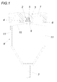
- Fig. 1
- eine nach dem erfindungsgemäßen Verfahren markierte, gegossene Betondecke im Bereich eines Markierungskörpers in einem Querschnitt und
- Fig. 2
- eine erfindungsgemäße Vorrichtung zum Orten von in eine Betondecke eingegossenen Markierungskörpern in einer zum Teil aufgerissenen Seitenansicht.
- Fig. 1
- a cast concrete ceiling marked according to the method of the invention in the region of a marking body in a cross-section and
- Fig. 2
- a device according to the invention for locating encapsulated in a concrete pavement marker bodies in a partially torn side view.
Wie der
Zu diesem Zweck ist gemäß der
Um einen Markierungskörper 2 in der Betondecke 1 zu orten und den durch diesen Markierungskörper 2 bestimmten Messpunkt auf der Putzschicht 6 festzulegen, wird die Führung 8 über den Handgriff 7 so entlang der Putzschicht 6 geführt, dass der Ortungsring 9 in den magnetischen Einflussbereich des magnetischen Markierungsrings gelangt, wie dies in der
Die Erfindung ist selbstverständlich nicht auf das dargestellte Ausführungsbeispiel beschränkt. So könnte das Zugmittel 10 eine in Bezug auf den gegenseitigen Abstand der Schenkel 11 der Führung 8 eine Überlänge aufweisen, sodass der magnetische Ortungsring 9 im Rahmen dieser Überlänge frei beweglich verlagert werden kann. Außerdem müsste der Ortungsring 9 nicht aus einem magnetischen Werkstoff gefertigt sein, sondern könnte auch aus einem ferromagnetischen Werkstoff bestehen, wenn die Markierungsringe 3 Permanentmagneten bilden.The invention is of course not limited to the illustrated embodiment. Thus, the traction means 10 could have an excess length with respect to the mutual distance of the
Claims (4)
Applications Claiming Priority (1)
| Application Number | Priority Date | Filing Date | Title |
|---|---|---|---|
| ATA50740/2013A AT515068B1 (en) | 2013-11-06 | 2013-11-06 | Method for marking a measuring point in a poured concrete ceiling |
Publications (2)
| Publication Number | Publication Date |
|---|---|
| EP2871497A1 true EP2871497A1 (en) | 2015-05-13 |
| EP2871497B1 EP2871497B1 (en) | 2017-02-22 |
Family
ID=51870867
Family Applications (1)
| Application Number | Title | Priority Date | Filing Date |
|---|---|---|---|
| EP14191485.3A Active EP2871497B1 (en) | 2013-11-06 | 2014-11-03 | Method for marking a measurement point in a cast concrete ceiling and apparatus for signaling a measurement point |
Country Status (2)
| Country | Link |
|---|---|
| EP (1) | EP2871497B1 (en) |
| AT (1) | AT515068B1 (en) |
Families Citing this family (2)
| Publication number | Priority date | Publication date | Assignee | Title |
|---|---|---|---|---|
| DE102016011611A1 (en) | 2016-09-26 | 2018-03-29 | Liebherr-Aerospace Lindenberg Gmbh | Sensor arrangement and aircraft |
| AT17567U1 (en) | 2021-05-31 | 2022-07-15 | Ke Kelit Gmbh | Device for fixing support rails for surface heating pipes |
Citations (6)
| Publication number | Priority date | Publication date | Assignee | Title |
|---|---|---|---|---|
| GB1506541A (en) * | 1975-02-06 | 1978-04-05 | Bassani Spa | Connections for securing boxes to walls of formers for cast prefabricated panels |
| GB2066587A (en) * | 1979-12-20 | 1981-07-08 | Wester B | Device for locating in building the exact position of hidden objects |
| JPS58111776A (en) * | 1981-12-25 | 1983-07-02 | Hitachi Metals Ltd | Piping detector |
| WO1988002852A1 (en) * | 1986-10-17 | 1988-04-21 | K.G. Derman Aktiebolag | Method and device for locating concealed junction boxes |
| GB2407166A (en) * | 2003-10-18 | 2005-04-20 | Richard Moorfield | Hidden cavity location system using magnetic target and detector |
| US20060288576A1 (en) * | 2005-06-28 | 2006-12-28 | Mark Sipe | Method and system for locating sites hidden behind a covering surface |
Family Cites Families (4)
| Publication number | Priority date | Publication date | Assignee | Title |
|---|---|---|---|---|
| JP4074845B2 (en) * | 2003-09-22 | 2008-04-16 | 清水建設株式会社 | Inking method and inking device |
| WO2008064851A2 (en) * | 2006-12-01 | 2008-06-05 | Leica Geosystems Ag | Localization system for an earth moving machine |
| CA2737488C (en) * | 2011-04-05 | 2014-04-22 | Graham Clarke | Junction box locator |
| DE102011017472A1 (en) * | 2011-04-16 | 2012-10-18 | Meese GmbH | Fixing structure used for partly potting in concrete element used in e.g. civil engineering application, has hollow section that is formed in fixing portion |
-
2013
- 2013-11-06 AT ATA50740/2013A patent/AT515068B1/en active
-
2014
- 2014-11-03 EP EP14191485.3A patent/EP2871497B1/en active Active
Patent Citations (6)
| Publication number | Priority date | Publication date | Assignee | Title |
|---|---|---|---|---|
| GB1506541A (en) * | 1975-02-06 | 1978-04-05 | Bassani Spa | Connections for securing boxes to walls of formers for cast prefabricated panels |
| GB2066587A (en) * | 1979-12-20 | 1981-07-08 | Wester B | Device for locating in building the exact position of hidden objects |
| JPS58111776A (en) * | 1981-12-25 | 1983-07-02 | Hitachi Metals Ltd | Piping detector |
| WO1988002852A1 (en) * | 1986-10-17 | 1988-04-21 | K.G. Derman Aktiebolag | Method and device for locating concealed junction boxes |
| GB2407166A (en) * | 2003-10-18 | 2005-04-20 | Richard Moorfield | Hidden cavity location system using magnetic target and detector |
| US20060288576A1 (en) * | 2005-06-28 | 2006-12-28 | Mark Sipe | Method and system for locating sites hidden behind a covering surface |
Also Published As
| Publication number | Publication date |
|---|---|
| AT515068B1 (en) | 2021-10-15 |
| AT515068A1 (en) | 2015-05-15 |
| EP2871497B1 (en) | 2017-02-22 |
Similar Documents
| Publication | Publication Date | Title |
|---|---|---|
| EP2871497B1 (en) | Method for marking a measurement point in a cast concrete ceiling and apparatus for signaling a measurement point | |
| AT392359B (en) | EXTENSOMETER | |
| DE19607254C2 (en) | Hollow body for the concrete building installation | |
| DE102007028560A1 (en) | Magnetic device for fixing shuttering device on shuttering support, has magnetic body laterally held with limb and connecting surfaces of housing by retaining element e.g. bolt, in non-functioning position in form-fit and force-fit manner | |
| EP2881523B1 (en) | Method for marking a measurement point in a cast concrete ceiling | |
| DE1955737C3 (en) | Drainage channel | |
| DE2229581A1 (en) | ADJUSTING ROAD MARKER POST | |
| EP2871305B1 (en) | Method for marking a measurement point in a cast concrete ceiling | |
| DE202022102627U1 (en) | Device for fixing support rails for surface heating pipes | |
| DE102013223401A1 (en) | Targeting device for a surveying system | |
| DE102009017942B4 (en) | Console device for supporting masonry | |
| DE102011052736A1 (en) | Anchor for use with anchor assembly for anchoring layer of multilayered finished component for distance fixing with another layer of multilayered finished component, has anchor element moved for anchoring of layer to certain side | |
| DE202009009919U1 (en) | Magnetic position sensor | |
| DE202005004628U1 (en) | Support mast consists of metal vertically installed pillar with open profile cross section, and extension section fastened to pillar with height adjustment capability | |
| DE102005016030A1 (en) | Heat-insulating and vibration-damping sleeve for pipes has transponders mounted in it, e.g. between layer of foam and outer foil cover, which transmit data regarding condition of sleeve and pipes and flow through them | |
| DE7413765U (en) | Device for locating steel dowels in concrete pavement ceilings and for creating dowel markings on the pavement | |
| DE202008015897U1 (en) | Identification device for paving elements | |
| DE536921C (en) | Multi-part clamping device for shuttering concrete masonry | |
| DE202023105405U1 (en) | Device for positioning and protecting an axial dynamometer | |
| DE202012102366U1 (en) | Device for attaching a beacon to a barrier fence | |
| DE8120862U1 (en) | KEY ROD | |
| AT226300B (en) | Method for anchoring a longitudinally and transversely armored cable laid in a cable duct in the vicinity of a cable connection point | |
| EP1353145A2 (en) | Method of aligning building components | |
| DE3400392A1 (en) | Process and apparatus for establishing reference points and for establishing distances and directions | |
| EP1544378A1 (en) | Method for installing an anchoring device for a slab edge shuttering and anchoring device to carry out the method |
Legal Events
| Date | Code | Title | Description |
|---|---|---|---|
| PUAI | Public reference made under article 153(3) epc to a published international application that has entered the european phase |
Free format text: ORIGINAL CODE: 0009012 |
|
| 17P | Request for examination filed |
Effective date: 20141103 |
|
| AK | Designated contracting states |
Kind code of ref document: A1 Designated state(s): AL AT BE BG CH CY CZ DE DK EE ES FI FR GB GR HR HU IE IS IT LI LT LU LV MC MK MT NL NO PL PT RO RS SE SI SK SM TR |
|
| AX | Request for extension of the european patent |
Extension state: BA ME |
|
| R17P | Request for examination filed (corrected) |
Effective date: 20151112 |
|
| RBV | Designated contracting states (corrected) |
Designated state(s): AL AT BE BG CH CY CZ DE DK EE ES FI FR GB GR HR HU IE IS IT LI LT LU LV MC MK MT NL NO PL PT RO RS SE SI SK SM TR |
|
| GRAP | Despatch of communication of intention to grant a patent |
Free format text: ORIGINAL CODE: EPIDOSNIGR1 |
|
| INTG | Intention to grant announced |
Effective date: 20160629 |
|
| GRAJ | Information related to disapproval of communication of intention to grant by the applicant or resumption of examination proceedings by the epo deleted |
Free format text: ORIGINAL CODE: EPIDOSDIGR1 |
|
| GRAP | Despatch of communication of intention to grant a patent |
Free format text: ORIGINAL CODE: EPIDOSNIGR1 |
|
| INTC | Intention to grant announced (deleted) | ||
| INTG | Intention to grant announced |
Effective date: 20161028 |
|
| RAP1 | Party data changed (applicant data changed or rights of an application transferred) |
Owner name: KE KELIT KUNSTSTOFFWERK GESELLSCHAFT M.B.H. |
|
| GRAS | Grant fee paid |
Free format text: ORIGINAL CODE: EPIDOSNIGR3 |
|
| GRAA | (expected) grant |
Free format text: ORIGINAL CODE: 0009210 |
|
| AK | Designated contracting states |
Kind code of ref document: B1 Designated state(s): AL AT BE BG CH CY CZ DE DK EE ES FI FR GB GR HR HU IE IS IT LI LT LU LV MC MK MT NL NO PL PT RO RS SE SI SK SM TR |
|
| REG | Reference to a national code |
Ref country code: GB Ref legal event code: FG4D Free format text: NOT ENGLISH |
|
| REG | Reference to a national code |
Ref country code: CH Ref legal event code: EP Ref country code: CH Ref legal event code: NV Representative=s name: E. BLUM AND CO. AG PATENT- UND MARKENANWAELTE , CH |
|
| REG | Reference to a national code |
Ref country code: AT Ref legal event code: REF Ref document number: 869692 Country of ref document: AT Kind code of ref document: T Effective date: 20170315 |
|
| REG | Reference to a national code |
Ref country code: IE Ref legal event code: FG4D Free format text: LANGUAGE OF EP DOCUMENT: GERMAN |
|
| REG | Reference to a national code |
Ref country code: DE Ref legal event code: R096 Ref document number: 502014002760 Country of ref document: DE |
|
| REG | Reference to a national code |
Ref country code: LT Ref legal event code: MG4D |
|
| REG | Reference to a national code |
Ref country code: NL Ref legal event code: MP Effective date: 20170222 |
|
| PG25 | Lapsed in a contracting state [announced via postgrant information from national office to epo] |
Ref country code: HR Free format text: LAPSE BECAUSE OF FAILURE TO SUBMIT A TRANSLATION OF THE DESCRIPTION OR TO PAY THE FEE WITHIN THE PRESCRIBED TIME-LIMIT Effective date: 20170222 Ref country code: NO Free format text: LAPSE BECAUSE OF FAILURE TO SUBMIT A TRANSLATION OF THE DESCRIPTION OR TO PAY THE FEE WITHIN THE PRESCRIBED TIME-LIMIT Effective date: 20170522 Ref country code: FI Free format text: LAPSE BECAUSE OF FAILURE TO SUBMIT A TRANSLATION OF THE DESCRIPTION OR TO PAY THE FEE WITHIN THE PRESCRIBED TIME-LIMIT Effective date: 20170222 Ref country code: LT Free format text: LAPSE BECAUSE OF FAILURE TO SUBMIT A TRANSLATION OF THE DESCRIPTION OR TO PAY THE FEE WITHIN THE PRESCRIBED TIME-LIMIT Effective date: 20170222 Ref country code: GR Free format text: LAPSE BECAUSE OF FAILURE TO SUBMIT A TRANSLATION OF THE DESCRIPTION OR TO PAY THE FEE WITHIN THE PRESCRIBED TIME-LIMIT Effective date: 20170523 |
|
| PG25 | Lapsed in a contracting state [announced via postgrant information from national office to epo] |
Ref country code: ES Free format text: LAPSE BECAUSE OF FAILURE TO SUBMIT A TRANSLATION OF THE DESCRIPTION OR TO PAY THE FEE WITHIN THE PRESCRIBED TIME-LIMIT Effective date: 20170222 Ref country code: NL Free format text: LAPSE BECAUSE OF FAILURE TO SUBMIT A TRANSLATION OF THE DESCRIPTION OR TO PAY THE FEE WITHIN THE PRESCRIBED TIME-LIMIT Effective date: 20170222 Ref country code: LV Free format text: LAPSE BECAUSE OF FAILURE TO SUBMIT A TRANSLATION OF THE DESCRIPTION OR TO PAY THE FEE WITHIN THE PRESCRIBED TIME-LIMIT Effective date: 20170222 Ref country code: SE Free format text: LAPSE BECAUSE OF FAILURE TO SUBMIT A TRANSLATION OF THE DESCRIPTION OR TO PAY THE FEE WITHIN THE PRESCRIBED TIME-LIMIT Effective date: 20170222 Ref country code: PT Free format text: LAPSE BECAUSE OF FAILURE TO SUBMIT A TRANSLATION OF THE DESCRIPTION OR TO PAY THE FEE WITHIN THE PRESCRIBED TIME-LIMIT Effective date: 20170622 Ref country code: BG Free format text: LAPSE BECAUSE OF FAILURE TO SUBMIT A TRANSLATION OF THE DESCRIPTION OR TO PAY THE FEE WITHIN THE PRESCRIBED TIME-LIMIT Effective date: 20170522 Ref country code: RS Free format text: LAPSE BECAUSE OF FAILURE TO SUBMIT A TRANSLATION OF THE DESCRIPTION OR TO PAY THE FEE WITHIN THE PRESCRIBED TIME-LIMIT Effective date: 20170222 |
|
| PG25 | Lapsed in a contracting state [announced via postgrant information from national office to epo] |
Ref country code: CZ Free format text: LAPSE BECAUSE OF FAILURE TO SUBMIT A TRANSLATION OF THE DESCRIPTION OR TO PAY THE FEE WITHIN THE PRESCRIBED TIME-LIMIT Effective date: 20170222 Ref country code: RO Free format text: LAPSE BECAUSE OF FAILURE TO SUBMIT A TRANSLATION OF THE DESCRIPTION OR TO PAY THE FEE WITHIN THE PRESCRIBED TIME-LIMIT Effective date: 20170222 Ref country code: SK Free format text: LAPSE BECAUSE OF FAILURE TO SUBMIT A TRANSLATION OF THE DESCRIPTION OR TO PAY THE FEE WITHIN THE PRESCRIBED TIME-LIMIT Effective date: 20170222 Ref country code: EE Free format text: LAPSE BECAUSE OF FAILURE TO SUBMIT A TRANSLATION OF THE DESCRIPTION OR TO PAY THE FEE WITHIN THE PRESCRIBED TIME-LIMIT Effective date: 20170222 Ref country code: IT Free format text: LAPSE BECAUSE OF FAILURE TO SUBMIT A TRANSLATION OF THE DESCRIPTION OR TO PAY THE FEE WITHIN THE PRESCRIBED TIME-LIMIT Effective date: 20170222 |
|
| REG | Reference to a national code |
Ref country code: DE Ref legal event code: R097 Ref document number: 502014002760 Country of ref document: DE |
|
| PG25 | Lapsed in a contracting state [announced via postgrant information from national office to epo] |
Ref country code: PL Free format text: LAPSE BECAUSE OF FAILURE TO SUBMIT A TRANSLATION OF THE DESCRIPTION OR TO PAY THE FEE WITHIN THE PRESCRIBED TIME-LIMIT Effective date: 20170222 Ref country code: DK Free format text: LAPSE BECAUSE OF FAILURE TO SUBMIT A TRANSLATION OF THE DESCRIPTION OR TO PAY THE FEE WITHIN THE PRESCRIBED TIME-LIMIT Effective date: 20170222 Ref country code: SM Free format text: LAPSE BECAUSE OF FAILURE TO SUBMIT A TRANSLATION OF THE DESCRIPTION OR TO PAY THE FEE WITHIN THE PRESCRIBED TIME-LIMIT Effective date: 20170222 |
|
| PLBE | No opposition filed within time limit |
Free format text: ORIGINAL CODE: 0009261 |
|
| STAA | Information on the status of an ep patent application or granted ep patent |
Free format text: STATUS: NO OPPOSITION FILED WITHIN TIME LIMIT |
|
| 26N | No opposition filed |
Effective date: 20171123 |
|
| PG25 | Lapsed in a contracting state [announced via postgrant information from national office to epo] |
Ref country code: SI Free format text: LAPSE BECAUSE OF FAILURE TO SUBMIT A TRANSLATION OF THE DESCRIPTION OR TO PAY THE FEE WITHIN THE PRESCRIBED TIME-LIMIT Effective date: 20170222 |
|
| PG25 | Lapsed in a contracting state [announced via postgrant information from national office to epo] |
Ref country code: MC Free format text: LAPSE BECAUSE OF FAILURE TO SUBMIT A TRANSLATION OF THE DESCRIPTION OR TO PAY THE FEE WITHIN THE PRESCRIBED TIME-LIMIT Effective date: 20170222 |
|
| PG25 | Lapsed in a contracting state [announced via postgrant information from national office to epo] |
Ref country code: LU Free format text: LAPSE BECAUSE OF NON-PAYMENT OF DUE FEES Effective date: 20171103 |
|
| REG | Reference to a national code |
Ref country code: FR Ref legal event code: ST Effective date: 20180731 Ref country code: BE Ref legal event code: MM Effective date: 20171130 |
|
| REG | Reference to a national code |
Ref country code: IE Ref legal event code: MM4A |
|
| PG25 | Lapsed in a contracting state [announced via postgrant information from national office to epo] |
Ref country code: MT Free format text: LAPSE BECAUSE OF FAILURE TO SUBMIT A TRANSLATION OF THE DESCRIPTION OR TO PAY THE FEE WITHIN THE PRESCRIBED TIME-LIMIT Effective date: 20170222 |
|
| PG25 | Lapsed in a contracting state [announced via postgrant information from national office to epo] |
Ref country code: FR Free format text: LAPSE BECAUSE OF NON-PAYMENT OF DUE FEES Effective date: 20171130 Ref country code: IE Free format text: LAPSE BECAUSE OF NON-PAYMENT OF DUE FEES Effective date: 20171103 |
|
| PG25 | Lapsed in a contracting state [announced via postgrant information from national office to epo] |
Ref country code: BE Free format text: LAPSE BECAUSE OF NON-PAYMENT OF DUE FEES Effective date: 20171130 |
|
| PG25 | Lapsed in a contracting state [announced via postgrant information from national office to epo] |
Ref country code: HU Free format text: LAPSE BECAUSE OF FAILURE TO SUBMIT A TRANSLATION OF THE DESCRIPTION OR TO PAY THE FEE WITHIN THE PRESCRIBED TIME-LIMIT; INVALID AB INITIO Effective date: 20141103 |
|
| GBPC | Gb: european patent ceased through non-payment of renewal fee |
Effective date: 20181103 |
|
| PG25 | Lapsed in a contracting state [announced via postgrant information from national office to epo] |
Ref country code: CY Free format text: LAPSE BECAUSE OF FAILURE TO SUBMIT A TRANSLATION OF THE DESCRIPTION OR TO PAY THE FEE WITHIN THE PRESCRIBED TIME-LIMIT Effective date: 20170222 |
|
| PG25 | Lapsed in a contracting state [announced via postgrant information from national office to epo] |
Ref country code: MK Free format text: LAPSE BECAUSE OF FAILURE TO SUBMIT A TRANSLATION OF THE DESCRIPTION OR TO PAY THE FEE WITHIN THE PRESCRIBED TIME-LIMIT Effective date: 20170222 |
|
| PG25 | Lapsed in a contracting state [announced via postgrant information from national office to epo] |
Ref country code: GB Free format text: LAPSE BECAUSE OF NON-PAYMENT OF DUE FEES Effective date: 20181103 |
|
| PG25 | Lapsed in a contracting state [announced via postgrant information from national office to epo] |
Ref country code: TR Free format text: LAPSE BECAUSE OF FAILURE TO SUBMIT A TRANSLATION OF THE DESCRIPTION OR TO PAY THE FEE WITHIN THE PRESCRIBED TIME-LIMIT Effective date: 20170222 |
|
| PG25 | Lapsed in a contracting state [announced via postgrant information from national office to epo] |
Ref country code: AL Free format text: LAPSE BECAUSE OF FAILURE TO SUBMIT A TRANSLATION OF THE DESCRIPTION OR TO PAY THE FEE WITHIN THE PRESCRIBED TIME-LIMIT Effective date: 20170222 Ref country code: IS Free format text: LAPSE BECAUSE OF FAILURE TO SUBMIT A TRANSLATION OF THE DESCRIPTION OR TO PAY THE FEE WITHIN THE PRESCRIBED TIME-LIMIT Effective date: 20170622 |
|
| REG | Reference to a national code |
Ref country code: AT Ref legal event code: MM01 Ref document number: 869692 Country of ref document: AT Kind code of ref document: T Effective date: 20191103 |
|
| PG25 | Lapsed in a contracting state [announced via postgrant information from national office to epo] |
Ref country code: AT Free format text: LAPSE BECAUSE OF NON-PAYMENT OF DUE FEES Effective date: 20191103 |
|
| P01 | Opt-out of the competence of the unified patent court (upc) registered |
Effective date: 20230505 |
|
| PGFP | Annual fee paid to national office [announced via postgrant information from national office to epo] |
Ref country code: DE Payment date: 20231127 Year of fee payment: 10 Ref country code: CH Payment date: 20231201 Year of fee payment: 10 |