EP2871473B1 - Ionisationssensor - Google Patents
Ionisationssensor Download PDFInfo
- Publication number
- EP2871473B1 EP2871473B1 EP14185687.2A EP14185687A EP2871473B1 EP 2871473 B1 EP2871473 B1 EP 2871473B1 EP 14185687 A EP14185687 A EP 14185687A EP 2871473 B1 EP2871473 B1 EP 2871473B1
- Authority
- EP
- European Patent Office
- Prior art keywords
- measurement
- test
- current
- electrodes
- sensor
- Prior art date
- Legal status (The legal status is an assumption and is not a legal conclusion. Google has not performed a legal analysis and makes no representation as to the accuracy of the status listed.)
- Active
Links
- 238000005259 measurement Methods 0.000 claims description 55
- 238000000034 method Methods 0.000 claims description 11
- 238000002485 combustion reaction Methods 0.000 claims description 8
- 230000035945 sensitivity Effects 0.000 claims description 8
- 230000002123 temporal effect Effects 0.000 claims description 3
- 239000007789 gas Substances 0.000 description 41
- 238000010438 heat treatment Methods 0.000 description 8
- 230000006870 function Effects 0.000 description 7
- 230000032683 aging Effects 0.000 description 4
- 238000011156 evaluation Methods 0.000 description 3
- 238000004364 calculation method Methods 0.000 description 2
- 230000001419 dependent effect Effects 0.000 description 2
- 238000010586 diagram Methods 0.000 description 2
- XLYOFNOQVPJJNP-UHFFFAOYSA-N water Substances O XLYOFNOQVPJJNP-UHFFFAOYSA-N 0.000 description 2
- 230000015572 biosynthetic process Effects 0.000 description 1
- 238000011109 contamination Methods 0.000 description 1
- 238000001514 detection method Methods 0.000 description 1
- 239000000446 fuel Substances 0.000 description 1
- 239000002737 fuel gas Substances 0.000 description 1
- 239000000203 mixture Substances 0.000 description 1
Images
Classifications
-
- G—PHYSICS
- G01—MEASURING; TESTING
- G01N—INVESTIGATING OR ANALYSING MATERIALS BY DETERMINING THEIR CHEMICAL OR PHYSICAL PROPERTIES
- G01N30/00—Investigating or analysing materials by separation into components using adsorption, absorption or similar phenomena or using ion-exchange, e.g. chromatography or field flow fractionation
- G01N30/02—Column chromatography
- G01N30/62—Detectors specially adapted therefor
- G01N30/64—Electrical detectors
- G01N30/68—Flame ionisation detectors
-
- G—PHYSICS
- G01—MEASURING; TESTING
- G01N—INVESTIGATING OR ANALYSING MATERIALS BY DETERMINING THEIR CHEMICAL OR PHYSICAL PROPERTIES
- G01N27/00—Investigating or analysing materials by the use of electric, electrochemical, or magnetic means
- G01N27/62—Investigating or analysing materials by the use of electric, electrochemical, or magnetic means by investigating the ionisation of gases, e.g. aerosols; by investigating electric discharges, e.g. emission of cathode
- G01N27/626—Investigating or analysing materials by the use of electric, electrochemical, or magnetic means by investigating the ionisation of gases, e.g. aerosols; by investigating electric discharges, e.g. emission of cathode using heat to ionise a gas
Definitions
- the invention relates to a sensor for measuring an ionization of a gas flame according to claim 1 and a method for calibrating an arrangement for measuring an ionization of a gas flame of a heating system.
- the senor has an electrode.
- the electrode is located in the area of the gas flame during the measurement.
- a voltage is applied between the gas nozzle and the electrode, and the ionization of the gas flame and thus the quality of the combustion are assessed on the basis of the flowing current.
- DE 20 2005 003 642 U1 describes a laboratory gas burner with a burner head, to which a combustible gas mixture can be fed via a fuel gas supply line, with conductivity measuring means for detecting an electrical conductivity in the area of the burner head, comprising an electrode to which an electrical measuring voltage can be applied and a counter electrode, with evaluation means for evaluating the detected conductivity to determine a fault and to determine the formation of a flame on the burner head, with control means for controlling functions of the laboratory gas burner and for converting the functions into a fault mode depending on the detection of a fault by the evaluation means.
- the measuring voltage has an electrical alternating voltage with a first and a second half-wave profile and the evaluation means are designed to measure the current flow between the electrode and the counter electrode during the first half-wave profile and during the second half-wave profile and to evaluate this as an indication of a fault.
- the object of the invention is to provide an improved sensor for measuring ionization of a gas flame and an improved method for calibrating a sensor.
- the object of the invention is achieved by the sensor according to claim 1 and by the method according to claim 7.
- An advantage of the sensor described is that the distance between the two electrodes of the sensor is precisely defined. This is achieved in that the two electrodes are arranged on a housing of the sensor.
- Another advantage of the sensor is that a voltage source is provided, with which a voltage can be generated at which the air is ionized even without a gas flame. This means that the sensor can be calibrated even without a gas flame, i.e. be carried out without operating the heating system.
- the measurement circuit is designed to determine a comparison value for a measurement sensitivity of the electrodes without a gas flame as a function of a test current.
- the comparison value is taken into account when measuring the ionization of the gas flame. In this way, aging of the electrodes can easily be taken into account when measuring the ionization.
- various characteristic curves for assigning a measurement current to a value for the ionization of the gas of the gas flame are stored in the measurement circuit, the measurement circuit being designed to be dependent on to select one of the characteristic curves from a test current value. The aging of the electrodes can thus be taken into account in a simple manner.
- the described method has the advantage that the sensitivity of the sensor can be calibrated independently of the operation of the heating system. This is achieved in that a test voltage is applied to the electrodes of the sensor and a test current is measured between the electrodes during a test phase without a gas flame.
- the test voltage is sufficiently high to generate ionization in the air even without the presence of a gas flame. Voltages of, for example, 500 to 50,000 volts are used for this.
- a value for an ionization of the gas flame is determined depending on the test current determined and on a measurement current that is measured while a gas flame is present.
- a characteristic curve for the measurement sensitivity of the electrodes is determined after the test phase has been carried out and depending on the test current determined. During the measuring operation, a value for the ionization of the gas flame is determined depending on the measuring current and depending on the characteristic curve of the measuring circuit.
- a characteristic curve defines a specific ionization of the burning gas, in particular a lambda value, as a function of a measurement current.
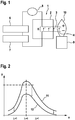
- FIG. 1 shows schematically the structure of the sensor 1.
- the sensor 1 has a housing 2, in which at least a first electrode 3 and a second electrode 4 are provided.
- the arrangement in the housing 2 means that the first and second electrodes 3, 4 are at a defined distance 5 from one another.
- the sensor 1 can have a voltage source 6 for generating a high voltage.
- the voltage source 6 can generate the two electrodes 3, 4 with a correspondingly high voltage in a test phase, so that ionization of the air takes place between the electrodes 3, 4.
- a measuring circuit 7 is also provided.
- the measuring circuit 7 comprises a current meter 8.
- a voltage can be applied to the electrodes 3, 4 using the voltage source 6.
- the current meter 8 is used to measure the current flowing between the electrodes 3, 4 both during the test phase and during the measurement phase and to report it to the measuring circuit 7.
- the measurement circuit 7 determines a value for the ionization of the gas flame during a measurement phase and a comparison value for the sensitivity of the electrodes 3, 4 which is used for a calibration of the electrodes 3, 4 during the measurement phase.
- Figure 1 schematically a nozzle 9 of a burner of a heating system is provided, which is connected to a gas source and is designed to emit gas and to generate a gas flame 10.
- the nozzle 9 is not supplied with gas, so that no gas flame 10 is generated.
- the test phase is independent of the operation of the heating system.
- a high voltage is applied to the electrodes 3, 4 using the voltage source 6.
- the voltage source 6 generates a voltage during the test phase, which can be, for example, in the range between 500 volts and 50,000 volts.
- the voltage is correspondingly high, so that measurable ionization of the atmosphere takes place without a gas flame 10 and the ammeter 8 can measure a test current.
- the flowing test current is measured using the ammeter 8.
- the measured test current is forwarded to the measuring circuit 7.
- the value of the test voltage which is applied by the voltage source 6 to the electrodes 3, 4 during the test phase, is preferably sent to the measuring circuit 7 transmitted.
- the measuring circuit 7 can also control the voltage source 6 and the value of the voltage.
- the ammeter 8 can detect a rise in the test current over time and a maximum test current and pass it on to the measuring circuit 7.
- the voltage source 6 can apply different test voltages to the electrodes 3, 4 during the test phase. For example, a predetermined test voltage profile with, for example, increasing and / or falling values from the voltage source can be applied to the electrodes during the test phase.
- the level of the test voltage can be varied during the test phase, so that not only a single test current value, but several test current values can be recorded for different test current voltages.
- test current and / or the temporal increase in the test current and / or a maximum value for the test current and / or the corresponding voltages of the voltage source can be used by the measuring circuit 7 to obtain a comparison value, in particular a characteristic curve for calibrating the measuring sensitivity of the electrodes during the Determine the measurement phase.
- a measurement voltage is generated between the electrodes 3, 4 using the voltage source 6 or using the further voltage source.
- the measuring voltage is lower than the test voltage.
- the measuring voltage is, for example, in the range between 5 and 100 volts.
- a gas flame 10 is generated by the nozzle 9 during the measurement phase and, at the same time, a measurement current is detected using the ammeter 8 and transmitted to the measurement circuit 7.
- the measuring circuit 7 determines a value for the ionization of the gas flame, in particular a ⁇ value of the gas flame, as a function of the measured current and the measured test current or as a function of the comparison value and / or the characteristic curve.
- the value for the ionization is output by the measuring circuit 7 and can be used, for example, for diagnosing the quality of the combustion and / or for controlling the combustion, in particular for controlling the mixing ratio of air and gas.
- Figure 2 shows a schematic representation of a diagram for two characteristic curves 11, 12 of the sensor 1 during a measurement of the ionization of a gas flame.
- Current values are microamperes ( ⁇ A) along and along the y-axis Lambda values for the gas flame are plotted on the x-axis.
- a lambda value less than 1 means a lack of air during combustion.
- a lambda value greater than 1 means excess air.
- the characteristic curves determine a dependency between a current flowing between the electrodes 3, 4 and an ionization of the gas flame, for example a lambda value.
- the first characteristic curve 11 corresponds to new electrodes 3, 4. During operation of the sensor 1, the electrodes 3, 4 are subject to aging.
- Aging can be influenced, for example, by contamination of the electrodes and / or damage to the electrodes.
- the sensitivity of the electrodes thus changes from the first characteristic curve 11 with increasing operating time in the direction of the second characteristic curve 12.
- the second characteristic curve 12 corresponds to a sensor 1 at the end of the service life.
- the characteristic curves can be stored in a memory of the measuring circuit. If predefined characteristic curves are stored, the stored characteristic curves can be assigned to different test currents or comparison values. The measuring circuit can thus select one of the stored characteristic curves depending on the measured test current and / or depending on the determined comparison value in order to be able to determine a value for the ionization of the gas flame on the basis of the measured measurement current. Thus, a precise statement about the ionization of the gases in the gas flame can be made during the measurement phase depending on the measured current.
- a characteristic curve is determined as a function of the test currents that are recorded during the test phase. Corresponding methods and calculation methods are stored in the measuring circuit 7 for this purpose.
- calculation formulas can be stored in the memory of the measuring circuit, with which a corresponding value for ionization of the gas flame, in particular a ⁇ value, can be calculated depending on a measured test current at a specified test voltage and depending on a specific measurement current during the measurement phase.
- the sensor and the method described can be used in particular in heating systems for hot water in order to reduce low NOx values to be able to stop the combustion.
Landscapes
- Chemical & Material Sciences (AREA)
- General Health & Medical Sciences (AREA)
- Life Sciences & Earth Sciences (AREA)
- Health & Medical Sciences (AREA)
- Analytical Chemistry (AREA)
- Biochemistry (AREA)
- Physics & Mathematics (AREA)
- General Physics & Mathematics (AREA)
- Immunology (AREA)
- Pathology (AREA)
- Chemical Kinetics & Catalysis (AREA)
- Electrochemistry (AREA)
- Other Investigation Or Analysis Of Materials By Electrical Means (AREA)
Description
- Die Erfindung betrifft einen Sensor zur Messung einer Ionisation einer Gasflamme gemäß Patentanspruch 1 und ein Verfahren zur Kalibrierung einer Anordnung zur Messung einer Ionisation einer Gasflamme einer Heizanlage gemäß Patentanspruch 7.
- Im Stand der Technik ist es bekannt, einen Sensor zur Messung einer Ionisation einer Gasflamme zu verwenden. Dazu weist der Sensor eine Elektrode auf. Die Elektrode befindet sich bei der Messung im Bereich der Gasflamme. Zur Messung wird eine Spannung zwischen der Gasdüse und der Elektrode angelegt und aufgrund des fließenden Stromes die Ionisation der Gasflamme und damit die Qualität der Verbrennung beurteilt.
-
DE 20 2005 003 642 U1 beschreibt einen Laborgasbrenner mit einem Brennerkopf, dem über eine Brenngaszuleitung ein brennbares Gasgemisch zuführbar ist, mit Leitfähigkeits-Messmitteln zur Erfassung einer elektrischen Leitfähigkeit im Bereich des Brennerkopfs, umfassend eine mit einer elektrischen Messspannung beaufschlagbare Elektrode und eine Gegenelektrode, mit Auswertemitteln zur Auswertung der erfassten Leitfähigkeit zur Feststellung einer Störung und zur Feststellung einer Flammenbildung am Brennerkopf, mit Steuermitteln zum Ansteuern von Funktionen des Laborgasbrenners und zum Überführen der Funktionen in einen Störmodus in Abhängigkeit von der Feststellung einer Störung durch die Auswertemittel. Die Messspannung weist eine elektrische Wechselspannung mit einem ersten und einem zweiten Halbwellenverlauf auf und die Auswertemittel sind ausgebildet, um während des ersten Halbwellenverlaufs und während des zweiten Halbwellenverlaufs den Stromfluss zwischen der Elektrode und der Gegenelektrode zu messen und als Hinweis auf eine Störung zu bewerten. - Die Aufgabe der Erfindung besteht darin, einen verbesserten Sensor zur Messung einer Ionisation einer Gasflamme und ein verbessertes Verfahren zur Kalibrierung eines Sensors bereitzustellen.
- Die Aufgabe der Erfindung wird durch den Sensor gemäß Patentanspruch 1 und durch das Verfahren gemäß Patentanspruch 7 gelöst.
- Weitere vorteilhafte Ausführungsformen sind in den abhängigen Ansprüchen angegeben.
- Ein Vorteil des beschriebenen Sensors besteht darin, dass der Abstand zwischen den zwei Elektroden des Sensors präzise festgelegt ist. Dies wird dadurch erreicht, dass die zwei Elektroden an einem Gehäuse des Sensors angeordnet sind. Ein weiterer Vorteil des Sensors besteht darin, dass eine Spannungsquelle vorgesehen ist, mit der eine Spannung erzeugt werden kann, bei der auch ohne Gasflamme eine Ionisation der Luft stattfindet. Somit kann eine Kalibrierung des Sensors auch ohne Gasflamme, d.h. ohne Betrieb der Heizanlage durchgeführt werden.
- Somit ist es nicht erforderlich, den Sensor während des Betriebes der Heizanlage zu kalibrieren. Damit kann Brennstoff eingespart werden. Zudem kann die Kalibrierung automatisch erfolgen.
- In einer Ausführungsform ist die Messschaltung ausgebildet ist, um abhängig von einem Teststrom einen Vergleichswert für eine Messempfindlichkeit der Elektroden ohne Gasflamme zu ermitteln. Der Vergleichswert wird bei der Messung der Ionisation der Gasflamme berücksichtigt. Somit kann auf einfache Weise eine Alterung der Elektroden bei der Messung der Ionisation berücksichtigt werden.
- In einer weiteren Ausführungsform sind verschiedene Kennlinien für eine Zuordnung eines Messstromes zu einem Wert für die Ionisation des Gases der Gasflamme in der Messschaltung abgelegt, wobei die Messschaltung ausgebildet ist, um abhängig von einem Teststromwert eine der Kennlinien auszuwählen. Damit kann die Alterung der Elektroden auf einfache Weise berücksichtigt werden.
- Das beschriebene Verfahren weist den Vorteil auf, dass eine Kalibrierung der Empfindlichkeit des Sensors unabhängig vom Betrieb der Heizanlage vorgenommen werden kann. Dies wird dadurch erreicht, dass während einer Testphase ohne Gasflamme eine Testspannung an die Elektroden des Sensors angelegt wird und ein Teststrom zwischen den Elektroden gemessen wird. Die Testspannung ist ausreichend hoch, um auch ohne das Vorhandensein einer Gasflamme eine Ionisation in der Luft zu erzeugen. Dazu werden Spannungen von beispielsweise 500 bis 50.000 Volt verwendet.
- Nach Durchführung der Testphase wird abhängig von dem ermittelten Teststrom und abhängig von einem Messstrom, der während des Vorhandenseins einer Gasflamme gemessen wird, ein Wert für eine Ionisation der Gasflamme ermittelt.
- In einer weiteren Ausführungsform wird nach Durchführung der Testphase und abhängig von dem ermittelten Teststrom eine Kennlinie für die Messempfindlichkeit der Elektroden ermittelt. Während des Messbetriebes wird abhängig vom Messstrom und abhängig von der Kennlinie von der Messschaltung ein Wert für die Ionisation der Gasflamme ermittelt.
- Für die Durchführung eines einfachen Verfahrens sind verschiedene Kennlinien für vorgegebene Testströme bei vorgegebenen Testspannungen in der Messschaltung abgespeichert. Somit kann die Messschaltung abhängig von einem gemessenen Teststrom eine entsprechende Kennlinie für die Beurteilung der Empfindlichkeit der Elektroden bei der Messung der Ionisation verwenden. Beispielsweise legt eine Kennlinie in Abhängigkeit von einem Messstrom eine bestimmte Ionisation des brennenden Gases, insbesondere einen Lambdawert fest.
- Die Erfindung wird im Folgenden anhand der Figuren näher erläutert. Es zeigen
- Figur 1
- einen Sensor und eine Gasdüse; und
- Figur 2
- ein Diagramm mit zwei Kennlinien.
-
Figur 1 zeigt schematisch den Aufbau des Sensors 1. Der Sensor 1 weist ein Gehäuse 2 auf, in dem wenigstens eine erste Elektrode 3 und eine zweite Elektrode 4 vorgesehen sind. Durch die Anordnung in dem Gehäuse 2 weisen die erste und die zweite Elektrode 3, 4 einen definierten Abstand 5 voneinander auf. Zudem kann abhängig von der gewählten Ausführungsform der Sensor 1 eine Spannungsquelle 6 zur Erzeugung einer Hochspannung aufweisen. Die Spannungsquelle 6 kann in einer Testphase die zwei Elektroden 3, 4 mit einer entsprechend hohen Spannung erzeugen, sodass zwischen den Elektroden 3, 4 eine Ionisation der Luft stattfindet. - Weiterhin ist eine Messschaltung 7 vorgesehen. Zudem umfasst die Messschaltung 7 einen Strommesser 8. Mithilfe der Spannungsquelle 6 kann eine Spannung an die Elektroden 3, 4 angelegt werden. Mithilfe des Strommessers 8 wird sowohl während der Testphase als auch während der Messphase der zwischen den Elektroden 3, 4 fließende Strom gemessen und an die Messschaltung 7 weiter gemeldet. Die Messschaltung 7 ermittelt während einer Messphase einen Wert für die Ionisation der Gasflamme und während einer Testphase einen Vergleichswert für die Empfindlichkeit der Elektroden 3,4, der für eine Kalibrierung der Elektroden 3,4 während der Messphase verwendet wird.
- Zudem ist in
Figur 1 schematisch eine Düse 9 eines Brenners einer Heizanlage vorgesehen, die mit einer Gasquelle verbunden ist und zur Abgabe von Gas und zum Erzeugen einer Gasflamme 10 ausgebildet ist. - Während einer Testphase wird die Düse 9 nicht mit Gas versorgt, sodass keine Gasflamme 10 erzeugt wird. Die Testphase ist unabhängig vom Betrieb der Heizanlage. Während der Testphase wird mithilfe der Spannungsquelle 6 eine Hochspannung an die Elektroden 3, 4 angelegt. Die Spannungsquelle 6 erzeugt während der Testphase eine Spannung, die beispielsweise im Bereich zwischen 500 Volt und 50.000 Volt liegen kann. Die Spannung ist entsprechend hoch, sodass ohne eine Gasflamme 10 eine messbare Ionisation der Atmosphäre stattfindet und der Strommesser 8 einen Teststrom messen kann. Während der Testphase wird mithilfe des Strommessers 8 der fließende Teststrom gemessen. Der gemessene Teststrom wird an die Messschaltung 7 weitergeleitet. Zudem wird vorzugsweise der Wert der Testspannung, die von der Spannungsquelle 6 während der Testphase an die Elektroden 3,4 angelegt wird, an die Messschaltung 7 übermittelt. Abhängig von der gewählten Ausführungsform kann die Messschaltung 7 auch die Spannungsquelle 6 und den Wert der Spannung steuern.
- Zudem kann der Strommesser 8 einen zeitlichen Anstieg des Teststromes und einen maximalen Teststrom erfassen und an die Messschaltung 7 weiter leiten. Weiterhin kann die Spannungsquelle 6 verschiedene Testspannungen während der Testphase an den Elektroden 3,4 anlegen. Beispielsweise kann ein vorgegebener Testspannungsverlauf mit beispielsweise steigender und/oder fallender Werte von der Spannungsquelle während der Testphase an die Elektroden angelegt werden. Beispielsweise kann während der Testphase die Testspannung in der Höhe variiert werden, sodass nicht nur ein einzelner Teststromwert, sondern mehrere Teststromwerte für verschiedene Teststromspannungen erfasst werden können. Der Teststrom und/oder die zeitliche Zunahme des Teststromes und/oder ein maximaler Wert für den Teststrom und/oder die entsprechenden Spannungen der Spannungsquelle können von der Messschaltung 7 verwendet werden, um einen Vergleichswert, insbesondere eine Kennlinie zur Kalibrierung der Messempfindlichkeit der Elektroden während der Messphase festzulegen.
- Während einer Messphase wird beispielsweise mithilfe der Spannungsquelle 6 oder mithilfe der weiteren Spannungsquelle eine Messspannung zwischen den Elektroden 3,4 erzeugt. Die Messspannung ist niedriger als die Testspannung. Die Messspannung liegt beispielsweise im Bereich zwischen 5 und 100 Volt. Zudem wird während der Messphase von der Düse 9 eine Gasflamme 10 erzeugt und gleichzeitig mithilfe des Strommessers 8 ein Messstrom erfasst und an die Messschaltung 7 übermittelt. Die Messschaltung 7 ermittelt abhängig von dem gemessenen Messstrom und dem gemessenen Teststrom beziehungsweise abhängig von dem ermittelten Vergleichswert und/oder der ermittelten Kennlinie einen Wert für die Ionisation der Gasflamme, insbesondere einem λ-Wert der Gasflamme. Der Wert für die Ionisation wird von der Messschaltung 7 ausgegeben und kann beispielsweise für eine Diagnose der Qualität der Verbrennung und/oder für eine Steuerung der Verbrennung, insbesondere für eine Steuerung des Mischungsverhältnisses von Luft und Gas verwendet werden.
-
Figur 2 zeigt in einer schematischen Darstellung ein Diagramm für zwei Kennlinien 11, 12 des Sensors 1 während einer Messung der Ionisation einer Gasflamme. Entlang der y-Achse sind Stromwerte Mikroampere (µA) und entlang der x-Achse sind Lambdawerte für die Gasflamme aufgetragen. Ein Lambdawert kleiner 1 bedeutet ein Luftmangel bei der Verbrennung. Ein Lambdawert größer 1 bedeutet ein Luftüberschuss. Die Kennlinien legen eine Abhängigkeit zwischen einem Strom, der zwischen den Elektroden 3, 4 fließt, und einer Ionisation der Gasflamme, beispielsweise einen Lambdawert, fest. Die erste Kennlinie 11 entspricht dabei neuen Elektroden 3, 4. Während des Betriebes des Sensors 1 sind die Elektroden 3, 4 einer Alterung unterworfen. Die Alterung kann beispielsweise durch eine Verschmutzung der Elektroden und/oder durch eine Beschädigung der Elektroden beeinflusst werden. Somit verändert sich die Empfindlichkeit der Elektroden von der ersten Kennlinie 11 mit zunehmender Betriebszeit in Richtung der zweiten Kennlinie 12. Die zweite Kennlinie 12 entspricht einem Sensor 1 am Ende der Lebensdauer. - Die Kennlinien können in einem Speicher der Messschaltung abgelegt sein. Sind vorgegebene Kennlinien abgespeichert, so können die abgespeicherten Kennlinien verschiedenen Testströmen oder Vergleichswerten zugeordnet sein. Somit kann die Messschaltung abhängig von dem gemessenen Teststrom und/oder abhängig vom ermittelten Vergleichswert eine der abgespeicherten Kennlinien auswählen, um anhand des gemessenen Messstromes einen Wert für die Ionisation der Gasflamme ermitteln zu können. Somit kann während der Messphase abhängig vom gemessenen Messstrom eine präzise Aussage über die Ionisation der Gase in der Gasflamme getroffen werden.
- In einer weiteren Ausführungsform wird eine Kennlinie abhängig von den Testströmen, die während der Testphase erfasst werden, ermittelt. Dazu sind entsprechende Verfahren und Berechnungsmethoden in der Messschaltung 7 abgespeichert.
- Zudem können Berechnungsformeln im Speicher der Messschaltung abgelegt sein, mit denen abhängig von einem gemessenen Teststrom bei einer festgelegten Testspannung und abhängig von einem bestimmten Messstrom während der Messphase ein entsprechender Wert für Ionisation der Gasflamme, insbesondere einen λ-Wert berechnet werden kann.
- Der beschriebene Sensor und das beschriebene Verfahren kann insbesondere bei Heizanlagen für Warmwasser eingesetzt werden, um niedrige NOx-Werte bei der Verbrennung einstellen zu können. Besonders bei Warmwasserheizungen ist es von Vorteil, wenn die Kalibrierung des Sensors automatisch ohne die Ausführung von Testverbrennungen durchgeführt werden kann.
Claims (10)
- Sensor (1) zur Messung einer Ionisation einer Gasflamme (10),- wobei zwei Elektroden (3, 4) vorgesehen sind, wobei die zwei Elektroden (3, 4) an einem Gehäuse (2) des Sensors (1) angeordnet sind,- wobei die Elektroden (3, 4) mit einer Spannungsquelle (6) verbunden sind,- wobei die Spannungsquelle (6) ausgebildet ist, um eine Spannung zu erzeugen, bei der eine Ionisation ohne Gasflamme (10) erzeugt wird,- wobei die Elektroden (3, 4) mit einer Messschaltung (7) verbunden sind,- wobei die Messschaltung (7) einen Strommesser (8) aufweist,- wobei der Strommesser (8) ausgebildet ist, um einen Strom zwischen den Elektroden (3, 4) zu messen,- wobei die Spannungsquelle (6) ausgebildet ist, während einer Testphase eine Testspannung und während einer Messphase eine niedrigere als die Testspannung ausgebildete Messspannung an den Elektroden (3, 4) des Sensors (1) anzulegen,- wobei der Strommesser (8) ausgebildet ist, einen Teststrom zwischen den Elektroden (3,4) während der Testphase zu messen und der Messschaltung (7) weiterzuleiten,- wobei während der Messphase während einer Verbrennung mit einer Gasflamme (10) der Sensor (1) in der Gasflamme (10) angeordnet ist,- wobei der Strommesser (8) ausgebildet ist, einen Messstrom zwischen den Elektroden (3,4) während der Messphase zu erfassen und der Messschaltung (7) weiterzuleiten,- wobei die Messschaltung (7) ausgebildet ist, abhängig von dem gemessenen Messstrom und dem gemessenen Teststrom einen Wert für die Ionisation der Gasflamme (10) zu ermitteln,- wobei die Messschaltung (7) ausgebildet ist, den Wert für die Ionisation auszugeben.
- Sensor (1) nach Anspruch 1, wobei die Messschaltung (7) ausgebildet ist, um während der Testphase aus dem gemessenen Teststromwert einen Vergleichswert für eine Messempfindlichkeit der Elektroden (3, 4) zu ermitteln.
- Sensor (1) nach Anspruch 2, wobei die Messschaltung (7) ausgebildet ist, um während der Messphase den Messstrom während der Verbrennung mit der Gasflamme (10) zu messen, wobei die Messschaltung (7) ausgebildet ist, um abhängig vom Messstrom und unter Berücksichtigung des Vergleichswertes einen Wert für die Ionisation der Gasflamme (10) zu ermitteln.
- Sensor (1) nach Anspruch 3, wobei verschiedene Kennlinien für eine Zuordnung eines Messstromes zu einem Wert für die Ionisation des Gases der Gasflamme in der Messschaltung abgelegt sind, wobei die Messschaltung ausgebildet ist, um abhängig von einem Teststromwert eine der Kennlinien auszuwählen.
- Sensor (1) nach einem der Ansprüche 2 bis 4, wobei die Messschaltung (7) ausgebildet ist, um abhängig von einem zeitlichen Verhalten des Teststromes und/oder einem maximalen Wert des Teststromes den Vergleichswert zu ermitteln.
- Sensor (1) nach einem derAnsprüche 2 bis 5, wobei die Messschaltung (7) ausgebildet ist, um abhängig von der Testspannung den Vergleichswert zu ermitteln.
- Verfahren zum Messen einer Ionisation einer Gasflamme (10), mit einem Sensor (1) mit zwei Elektroden (3, 4), wobei während einer Testphase ohne Gasflamme (10) eine Testspannung an die Elektroden (3, 4) des Sensors (1) angelegt wird, und ein Teststrom zwischen den Elektroden (3, 4) gemessen wird, wobei während einer Messphase während einer Verbrennung der Sensor (1) in der Gasflamme (10) angeordnet ist und eine Messspannung an die Elektroden (3, 4) des Sensors (1) angelegt wird und ein Messstrom gemessen wird, und wobei abhängig vom Messstrom und abhängig vom Teststrom ein Wert für die Ionisation der Gasflamme (10) ermittelt wird.
- Verfahren nach Anspruch 7, wobei abhängig vom gemessenen Teststrom wenigstens eine Kennlinie (11, 12) festgelegt wird, wobei die Kennlinie (11, 12) einen Zusammenhang zwischen dem Messstrom und einem Wert für eine Ionisation der Gasflamme (10) festlegt, und wobei abhängig von der Kennlinie (11, 12) und vom Messstrom ein Wert für die Ionisation der Gasflamme (10) ermittelt wird.
- Verfahren nach Anspruch 8, wobei abhängig vom zeitlichen Verhalten und/oder von einem Maximalwert des Teststroms eine Kennlinie (11, 12) ermittelt wird.
- Verfahren nach Anspruch 8 oder 9, wobei abhängig von der Testspannung eine Kennlinie (11, 12) ermittelt wird, und wobei die Kennlinie (11, 12) bei der Ermittlung der Ionisation berücksichtigt wird.
Applications Claiming Priority (1)
| Application Number | Priority Date | Filing Date | Title |
|---|---|---|---|
| DE201310222675 DE102013222675A1 (de) | 2013-11-07 | 2013-11-07 | Ionisationssensor |
Publications (2)
| Publication Number | Publication Date |
|---|---|
| EP2871473A1 EP2871473A1 (de) | 2015-05-13 |
| EP2871473B1 true EP2871473B1 (de) | 2020-07-08 |
Family
ID=51584999
Family Applications (1)
| Application Number | Title | Priority Date | Filing Date |
|---|---|---|---|
| EP14185687.2A Active EP2871473B1 (de) | 2013-11-07 | 2014-09-22 | Ionisationssensor |
Country Status (4)
| Country | Link |
|---|---|
| EP (1) | EP2871473B1 (de) |
| DE (1) | DE102013222675A1 (de) |
| ES (1) | ES2820726T3 (de) |
| PT (1) | PT2871473T (de) |
Family Cites Families (4)
| Publication number | Priority date | Publication date | Assignee | Title |
|---|---|---|---|---|
| CS154807B1 (de) * | 1972-05-15 | 1974-04-30 | ||
| DE10025769A1 (de) * | 2000-05-12 | 2001-11-15 | Siemens Building Tech Ag | Regeleinrichtung für einen Brenner |
| DE202005003642U1 (de) * | 2005-03-03 | 2005-05-25 | Schütt Labortechnik GmbH | Laborgasbrenner |
| DE102010055567B4 (de) * | 2010-12-21 | 2012-08-02 | Robert Bosch Gmbh | Verfahren zur Stabilisierung eines Betriebsverhaltens eines Gasgebläsebrenners |
-
2013
- 2013-11-07 DE DE201310222675 patent/DE102013222675A1/de not_active Ceased
-
2014
- 2014-09-22 EP EP14185687.2A patent/EP2871473B1/de active Active
- 2014-09-22 PT PT141856872T patent/PT2871473T/pt unknown
- 2014-09-22 ES ES14185687T patent/ES2820726T3/es active Active
Non-Patent Citations (1)
| Title |
|---|
| None * |
Also Published As
| Publication number | Publication date |
|---|---|
| EP2871473A1 (de) | 2015-05-13 |
| PT2871473T (pt) | 2020-08-20 |
| ES2820726T3 (es) | 2021-04-22 |
| DE102013222675A1 (de) | 2015-05-07 |
Similar Documents
| Publication | Publication Date | Title |
|---|---|---|
| EP2951573B1 (de) | Restöl-messgerät | |
| DE102009027378A1 (de) | Verfahren und Diagnosevorrichtung zur Diagnose einer beheizbaren Abgassonde einer Brennkraftmaschine | |
| DE4139325C1 (en) | Function monitoring soot filter in exhaust pipe of IC engine | |
| DE102012213068A1 (de) | Verfahren und Fehlersimulator zur Überprüfung der Fehlererkennung eines Steuergerätes | |
| WO2021197752A1 (de) | Verfahren zum ermitteln eines zustandsparameters eines abgassensors | |
| EP3775865B1 (de) | Flammenionisationsdetektor und verfahren zur analyse eines sauerstoffhaltigen messgases | |
| EP2871473B1 (de) | Ionisationssensor | |
| DE10001251B4 (de) | Verfahren zum Steuern oder Regeln eines Gasbrenners | |
| DE102014226922A1 (de) | Verfahren zur Diagnose von Verbindungsleitungen und Auswertevorrichtung zur Durchführung des Verfahrens | |
| DE102013202260A1 (de) | Verfahren und Vorrichtung zur Überwachung eines mehrzelligen Abgassensors | |
| DE102005024763B3 (de) | Heizgerät und Verfahren zum Steuern eines Heizgerätes | |
| EP3869099B1 (de) | Verfahren, vorrichtung und computerprogrammprodukt zur regelung eines brenngas-luft-gemisches in einem heizgerät bei variabler leistung | |
| DE2457650A1 (de) | Einrichtung zur ueberpruefung von gasen | |
| EP3825610B1 (de) | Verfahren und vorrichtung zur messung des lambda-wertes in einem fossil befeuerten brenner, insbesondere für eine heizungs- und/oder brauchwasseranlage | |
| DE102009057121A1 (de) | Verfahren zur qualitativen Überwachung und Regelung des Verbrennungszustandes eines Heizkesselsystems mittels eines Ionisationsflammenwächters | |
| DE112020001286T5 (de) | Gassensor-Steuerungsvorrichtung, Gassensor-Steuerungssystem und Gassensorsystem | |
| DE102006012461A1 (de) | Verfahren zur Bestimmung des dynamischen Verhaltens einer Abgassonde | |
| DE102021102063A1 (de) | Verfahren und Anordnung zum Erkennen und/oder Beobachten von Flammen in einem Heizgerät, insbesondere für Brennstoffe mit hohem Wasserstoffanteil | |
| DE102022208018B3 (de) | Verfahren und Gassensor zum Ermitteln der Konzentration einer Gaskomponente in einem Gasgemisch | |
| EP3045904B1 (de) | Verfahren zum betrieb einer magnetomechanische sensorvorrichtung zur paramagnetischen gasanalyse mit messung von störeinflüssen | |
| EP3605078A1 (de) | Flammenionisationsdetektor und verfahren zur analyse eines sauerstoffhaltigen messgases | |
| EP1500926B1 (de) | Verfahren zur Kompensation der Alterung eines Sensors zur Erfassung einer Gaskonzentration | |
| WO2001004541A1 (de) | Gasbrenner | |
| EP3173779B1 (de) | Verfahren zur funktionsüberprüfung eines gassensors | |
| DE102022208287A1 (de) | Verfahren zum Ermitteln eines Fehlers einer Gassensorvorrichtung und Gassensorvorrichtung |
Legal Events
| Date | Code | Title | Description |
|---|---|---|---|
| PUAI | Public reference made under article 153(3) epc to a published international application that has entered the european phase |
Free format text: ORIGINAL CODE: 0009012 |
|
| 17P | Request for examination filed |
Effective date: 20140922 |
|
| AK | Designated contracting states |
Kind code of ref document: A1 Designated state(s): AL AT BE BG CH CY CZ DE DK EE ES FI FR GB GR HR HU IE IS IT LI LT LU LV MC MK MT NL NO PL PT RO RS SE SI SK SM TR |
|
| AX | Request for extension of the european patent |
Extension state: BA ME |
|
| R17P | Request for examination filed (corrected) |
Effective date: 20151113 |
|
| RBV | Designated contracting states (corrected) |
Designated state(s): AL AT BE BG CH CY CZ DE DK EE ES FI FR GB GR HR HU IE IS IT LI LT LU LV MC MK MT NL NO PL PT RO RS SE SI SK SM TR |
|
| STAA | Information on the status of an ep patent application or granted ep patent |
Free format text: STATUS: EXAMINATION IS IN PROGRESS |
|
| 17Q | First examination report despatched |
Effective date: 20190725 |
|
| GRAP | Despatch of communication of intention to grant a patent |
Free format text: ORIGINAL CODE: EPIDOSNIGR1 |
|
| STAA | Information on the status of an ep patent application or granted ep patent |
Free format text: STATUS: GRANT OF PATENT IS INTENDED |
|
| RIC1 | Information provided on ipc code assigned before grant |
Ipc: F23D 14/46 20060101ALN20200123BHEP Ipc: G01N 30/68 20060101ALI20200123BHEP Ipc: G01N 27/62 20060101AFI20200123BHEP Ipc: F23N 5/12 20060101ALN20200123BHEP |
|
| RIC1 | Information provided on ipc code assigned before grant |
Ipc: F23N 5/12 20060101ALN20200203BHEP Ipc: G01N 30/68 20060101ALI20200203BHEP Ipc: G01N 27/62 20060101AFI20200203BHEP Ipc: F23D 14/46 20060101ALN20200203BHEP |
|
| INTG | Intention to grant announced |
Effective date: 20200219 |
|
| RAP1 | Party data changed (applicant data changed or rights of an application transferred) |
Owner name: ROBERT BOSCH GMBH |
|
| GRAS | Grant fee paid |
Free format text: ORIGINAL CODE: EPIDOSNIGR3 |
|
| GRAA | (expected) grant |
Free format text: ORIGINAL CODE: 0009210 |
|
| STAA | Information on the status of an ep patent application or granted ep patent |
Free format text: STATUS: THE PATENT HAS BEEN GRANTED |
|
| AK | Designated contracting states |
Kind code of ref document: B1 Designated state(s): AL AT BE BG CH CY CZ DE DK EE ES FI FR GB GR HR HU IE IS IT LI LT LU LV MC MK MT NL NO PL PT RO RS SE SI SK SM TR |
|
| REG | Reference to a national code |
Ref country code: AT Ref legal event code: REF Ref document number: 1289004 Country of ref document: AT Kind code of ref document: T Effective date: 20200715 Ref country code: CH Ref legal event code: EP |
|
| REG | Reference to a national code |
Ref country code: DE Ref legal event code: R096 Ref document number: 502014014411 Country of ref document: DE |
|
| REG | Reference to a national code |
Ref country code: IE Ref legal event code: FG4D Free format text: LANGUAGE OF EP DOCUMENT: GERMAN |
|
| REG | Reference to a national code |
Ref country code: PT Ref legal event code: SC4A Ref document number: 2871473 Country of ref document: PT Date of ref document: 20200820 Kind code of ref document: T Free format text: AVAILABILITY OF NATIONAL TRANSLATION Effective date: 20200805 |
|
| REG | Reference to a national code |
Ref country code: LT Ref legal event code: MG4D |
|
| REG | Reference to a national code |
Ref country code: NL Ref legal event code: MP Effective date: 20200708 |
|
| PG25 | Lapsed in a contracting state [announced via postgrant information from national office to epo] |
Ref country code: NO Free format text: LAPSE BECAUSE OF FAILURE TO SUBMIT A TRANSLATION OF THE DESCRIPTION OR TO PAY THE FEE WITHIN THE PRESCRIBED TIME-LIMIT Effective date: 20201008 Ref country code: FI Free format text: LAPSE BECAUSE OF FAILURE TO SUBMIT A TRANSLATION OF THE DESCRIPTION OR TO PAY THE FEE WITHIN THE PRESCRIBED TIME-LIMIT Effective date: 20200708 Ref country code: LT Free format text: LAPSE BECAUSE OF FAILURE TO SUBMIT A TRANSLATION OF THE DESCRIPTION OR TO PAY THE FEE WITHIN THE PRESCRIBED TIME-LIMIT Effective date: 20200708 Ref country code: HR Free format text: LAPSE BECAUSE OF FAILURE TO SUBMIT A TRANSLATION OF THE DESCRIPTION OR TO PAY THE FEE WITHIN THE PRESCRIBED TIME-LIMIT Effective date: 20200708 Ref country code: SE Free format text: LAPSE BECAUSE OF FAILURE TO SUBMIT A TRANSLATION OF THE DESCRIPTION OR TO PAY THE FEE WITHIN THE PRESCRIBED TIME-LIMIT Effective date: 20200708 Ref country code: BG Free format text: LAPSE BECAUSE OF FAILURE TO SUBMIT A TRANSLATION OF THE DESCRIPTION OR TO PAY THE FEE WITHIN THE PRESCRIBED TIME-LIMIT Effective date: 20201008 Ref country code: GR Free format text: LAPSE BECAUSE OF FAILURE TO SUBMIT A TRANSLATION OF THE DESCRIPTION OR TO PAY THE FEE WITHIN THE PRESCRIBED TIME-LIMIT Effective date: 20201009 |
|
| PG25 | Lapsed in a contracting state [announced via postgrant information from national office to epo] |
Ref country code: IS Free format text: LAPSE BECAUSE OF FAILURE TO SUBMIT A TRANSLATION OF THE DESCRIPTION OR TO PAY THE FEE WITHIN THE PRESCRIBED TIME-LIMIT Effective date: 20201108 Ref country code: LV Free format text: LAPSE BECAUSE OF FAILURE TO SUBMIT A TRANSLATION OF THE DESCRIPTION OR TO PAY THE FEE WITHIN THE PRESCRIBED TIME-LIMIT Effective date: 20200708 Ref country code: RS Free format text: LAPSE BECAUSE OF FAILURE TO SUBMIT A TRANSLATION OF THE DESCRIPTION OR TO PAY THE FEE WITHIN THE PRESCRIBED TIME-LIMIT Effective date: 20200708 Ref country code: PL Free format text: LAPSE BECAUSE OF FAILURE TO SUBMIT A TRANSLATION OF THE DESCRIPTION OR TO PAY THE FEE WITHIN THE PRESCRIBED TIME-LIMIT Effective date: 20200708 |
|
| PG25 | Lapsed in a contracting state [announced via postgrant information from national office to epo] |
Ref country code: NL Free format text: LAPSE BECAUSE OF FAILURE TO SUBMIT A TRANSLATION OF THE DESCRIPTION OR TO PAY THE FEE WITHIN THE PRESCRIBED TIME-LIMIT Effective date: 20200708 |
|
| REG | Reference to a national code |
Ref country code: DE Ref legal event code: R097 Ref document number: 502014014411 Country of ref document: DE |
|
| REG | Reference to a national code |
Ref country code: ES Ref legal event code: FG2A Ref document number: 2820726 Country of ref document: ES Kind code of ref document: T3 Effective date: 20210422 |
|
| PG25 | Lapsed in a contracting state [announced via postgrant information from national office to epo] |
Ref country code: CZ Free format text: LAPSE BECAUSE OF FAILURE TO SUBMIT A TRANSLATION OF THE DESCRIPTION OR TO PAY THE FEE WITHIN THE PRESCRIBED TIME-LIMIT Effective date: 20200708 Ref country code: EE Free format text: LAPSE BECAUSE OF FAILURE TO SUBMIT A TRANSLATION OF THE DESCRIPTION OR TO PAY THE FEE WITHIN THE PRESCRIBED TIME-LIMIT Effective date: 20200708 Ref country code: DK Free format text: LAPSE BECAUSE OF FAILURE TO SUBMIT A TRANSLATION OF THE DESCRIPTION OR TO PAY THE FEE WITHIN THE PRESCRIBED TIME-LIMIT Effective date: 20200708 Ref country code: IT Free format text: LAPSE BECAUSE OF FAILURE TO SUBMIT A TRANSLATION OF THE DESCRIPTION OR TO PAY THE FEE WITHIN THE PRESCRIBED TIME-LIMIT Effective date: 20200708 Ref country code: SM Free format text: LAPSE BECAUSE OF FAILURE TO SUBMIT A TRANSLATION OF THE DESCRIPTION OR TO PAY THE FEE WITHIN THE PRESCRIBED TIME-LIMIT Effective date: 20200708 Ref country code: RO Free format text: LAPSE BECAUSE OF FAILURE TO SUBMIT A TRANSLATION OF THE DESCRIPTION OR TO PAY THE FEE WITHIN THE PRESCRIBED TIME-LIMIT Effective date: 20200708 Ref country code: MC Free format text: LAPSE BECAUSE OF FAILURE TO SUBMIT A TRANSLATION OF THE DESCRIPTION OR TO PAY THE FEE WITHIN THE PRESCRIBED TIME-LIMIT Effective date: 20200708 |
|
| REG | Reference to a national code |
Ref country code: CH Ref legal event code: PL |
|
| PLBE | No opposition filed within time limit |
Free format text: ORIGINAL CODE: 0009261 |
|
| STAA | Information on the status of an ep patent application or granted ep patent |
Free format text: STATUS: NO OPPOSITION FILED WITHIN TIME LIMIT |
|
| PG25 | Lapsed in a contracting state [announced via postgrant information from national office to epo] |
Ref country code: AL Free format text: LAPSE BECAUSE OF FAILURE TO SUBMIT A TRANSLATION OF THE DESCRIPTION OR TO PAY THE FEE WITHIN THE PRESCRIBED TIME-LIMIT Effective date: 20200708 |
|
| 26N | No opposition filed |
Effective date: 20210409 |
|
| REG | Reference to a national code |
Ref country code: BE Ref legal event code: MM Effective date: 20200930 |
|
| GBPC | Gb: european patent ceased through non-payment of renewal fee |
Effective date: 20201008 |
|
| PG25 | Lapsed in a contracting state [announced via postgrant information from national office to epo] |
Ref country code: SK Free format text: LAPSE BECAUSE OF FAILURE TO SUBMIT A TRANSLATION OF THE DESCRIPTION OR TO PAY THE FEE WITHIN THE PRESCRIBED TIME-LIMIT Effective date: 20200708 Ref country code: LU Free format text: LAPSE BECAUSE OF NON-PAYMENT OF DUE FEES Effective date: 20200922 |
|
| PG25 | Lapsed in a contracting state [announced via postgrant information from national office to epo] |
Ref country code: FR Free format text: LAPSE BECAUSE OF NON-PAYMENT OF DUE FEES Effective date: 20200930 |
|
| PG25 | Lapsed in a contracting state [announced via postgrant information from national office to epo] |
Ref country code: SI Free format text: LAPSE BECAUSE OF FAILURE TO SUBMIT A TRANSLATION OF THE DESCRIPTION OR TO PAY THE FEE WITHIN THE PRESCRIBED TIME-LIMIT Effective date: 20200708 Ref country code: LI Free format text: LAPSE BECAUSE OF NON-PAYMENT OF DUE FEES Effective date: 20200930 Ref country code: IE Free format text: LAPSE BECAUSE OF NON-PAYMENT OF DUE FEES Effective date: 20200922 Ref country code: GB Free format text: LAPSE BECAUSE OF NON-PAYMENT OF DUE FEES Effective date: 20201008 Ref country code: CH Free format text: LAPSE BECAUSE OF NON-PAYMENT OF DUE FEES Effective date: 20200930 Ref country code: BE Free format text: LAPSE BECAUSE OF NON-PAYMENT OF DUE FEES Effective date: 20200930 |
|
| REG | Reference to a national code |
Ref country code: AT Ref legal event code: MM01 Ref document number: 1289004 Country of ref document: AT Kind code of ref document: T Effective date: 20200922 |
|
| PG25 | Lapsed in a contracting state [announced via postgrant information from national office to epo] |
Ref country code: AT Free format text: LAPSE BECAUSE OF NON-PAYMENT OF DUE FEES Effective date: 20200922 |
|
| PG25 | Lapsed in a contracting state [announced via postgrant information from national office to epo] |
Ref country code: TR Free format text: LAPSE BECAUSE OF FAILURE TO SUBMIT A TRANSLATION OF THE DESCRIPTION OR TO PAY THE FEE WITHIN THE PRESCRIBED TIME-LIMIT Effective date: 20200708 Ref country code: MT Free format text: LAPSE BECAUSE OF FAILURE TO SUBMIT A TRANSLATION OF THE DESCRIPTION OR TO PAY THE FEE WITHIN THE PRESCRIBED TIME-LIMIT Effective date: 20200708 Ref country code: CY Free format text: LAPSE BECAUSE OF FAILURE TO SUBMIT A TRANSLATION OF THE DESCRIPTION OR TO PAY THE FEE WITHIN THE PRESCRIBED TIME-LIMIT Effective date: 20200708 |
|
| PG25 | Lapsed in a contracting state [announced via postgrant information from national office to epo] |
Ref country code: MK Free format text: LAPSE BECAUSE OF FAILURE TO SUBMIT A TRANSLATION OF THE DESCRIPTION OR TO PAY THE FEE WITHIN THE PRESCRIBED TIME-LIMIT Effective date: 20200708 |
|
| PGFP | Annual fee paid to national office [announced via postgrant information from national office to epo] |
Ref country code: ES Payment date: 20231019 Year of fee payment: 10 |
|
| PGFP | Annual fee paid to national office [announced via postgrant information from national office to epo] |
Ref country code: DE Payment date: 20231124 Year of fee payment: 10 |
|
| PGFP | Annual fee paid to national office [announced via postgrant information from national office to epo] |
Ref country code: PT Payment date: 20240911 Year of fee payment: 11 |