EP2871472B1 - Support for electrode stack and provision for venting of a gas sensor using an internally mounted table - Google Patents
Support for electrode stack and provision for venting of a gas sensor using an internally mounted table Download PDFInfo
- Publication number
- EP2871472B1 EP2871472B1 EP14188914.7A EP14188914A EP2871472B1 EP 2871472 B1 EP2871472 B1 EP 2871472B1 EP 14188914 A EP14188914 A EP 14188914A EP 2871472 B1 EP2871472 B1 EP 2871472B1
- Authority
- EP
- European Patent Office
- Prior art keywords
- sensor
- electrode
- washer
- separator
- pad
- Prior art date
- Legal status (The legal status is an assumption and is not a legal conclusion. Google has not performed a legal analysis and makes no representation as to the accuracy of the status listed.)
- Active
Links
Images




Classifications
-
- G—PHYSICS
- G01—MEASURING; TESTING
- G01N—INVESTIGATING OR ANALYSING MATERIALS BY DETERMINING THEIR CHEMICAL OR PHYSICAL PROPERTIES
- G01N27/00—Investigating or analysing materials by the use of electric, electrochemical, or magnetic means
- G01N27/26—Investigating or analysing materials by the use of electric, electrochemical, or magnetic means by investigating electrochemical variables; by using electrolysis or electrophoresis
- G01N27/403—Cells and electrode assemblies
-
- G—PHYSICS
- G01—MEASURING; TESTING
- G01N—INVESTIGATING OR ANALYSING MATERIALS BY DETERMINING THEIR CHEMICAL OR PHYSICAL PROPERTIES
- G01N27/00—Investigating or analysing materials by the use of electric, electrochemical, or magnetic means
- G01N27/26—Investigating or analysing materials by the use of electric, electrochemical, or magnetic means by investigating electrochemical variables; by using electrolysis or electrophoresis
- G01N27/403—Cells and electrode assemblies
- G01N27/404—Cells with anode, cathode and cell electrolyte on the same side of a permeable membrane which separates them from the sample fluid, e.g. Clark-type oxygen sensors
Definitions
- the application pertains to electrochemical oxygen sensors. More particularly, the application pertains to such sensors, which have an external housing that supports an internally fitted table that supports an electrode stack assembly. Furthermore, this application relates to the use of Aclar® as a barrier material in electrochemical gas sensors.
- An oxygen pump sensor requires a vent in order to operate where oxygen gas is consumed at the sensing electrode and generated at the counter electrode.
- a connection to the exterior atmosphere is therefore required when the counter electrode is placed at the base of the electrode stack in order to vent the generated oxygen from inside the sensor.
- One method of providing venting to the counter electrode at the base of the stack is to extend a molded tube to meet the electrode (e.g. , the City Technology, ECO-OX).
- An electrode stack within an oxygen pump sensor also requires adequate physical support to maintain consistent stack compression.
- the compression of the electrode stack facilitates electrical contact with the current collectors, and ensures adequate transfer of electrolyte to the separators within the stack.
- GB Patent Publication GB 2303710 discloses an electrochemical toxic gas sensor with gas permeable membrane. The sensor is separated from the gas to be measured by a gas permeable membrane. The sensor also receives less contamination from other chemicals in the fluid.
- EP Patent Publication EP 2581734 discloses auxiliary micro-electrodes for diagnostics of electrochemical gas sensors.
- the present invention provides a sensor as defined in claim 1.
- the sensor may include the features of any one or more of dependent claims 2 to 11.
- the subject matter hereof provides a sensor having a two piece molding, comprising an existing main body containing terminal pins, a gas inlet port or hole in the base, and an internally fitted 'table', which supports the electrode stack assembly.
- the table has a hollow central leg, which is sealed into the sensor body with an epoxy, whose primary purpose is to prevent egress of electrolyte via the inserted terminal pins. Another purpose of the epoxy is to prevent corrosion of the pins, which can generate currents and will eventually make leakage more likely.
- the epoxy also serves to hold the table legs in place.
- the table's hollow central leg also supports the electrode stack assembled on top of it.
- One useful aspect of this design is that the use of PTFE counter tape promotes quick equalization of sensor interior pressure with the atmospheric pressure outside the sensor, greatly reducing the possibility of the sensor 'glitching'. Those of skill will understand how to select the grade of such tape.
- the 'table' is an injection molded item.
- the molded sensor initially has at least one current collector or wires welded to the top of the terminal pins.
- Epoxy is then dispensed into the base of the sensor body, covering the internal base of the sensor and the top of the terminal pins.
- the gas inlet port is a protrusion in the center of the base and sits above the height of the epoxy, so that the epoxy does not leak out of the sensor body molding during curing and to ensure that the epoxy does not get into the vent and obscure the hole.
- the lower viscosity also ensures the table settles correctly onto the floor of the sensor body molding, although a tight fitting table to sensor body protrusion also promotes positive, consistent location. In this way, a gas pathway has been created from the exterior base of the sensor body up to the bottom the electrode stack, which is situated at the top of the sensor body.
- the senor comprises a body having at least one terminal pin connected to at least one current collector, and a gas inlet port, a table with a gas inlet port in alignment with the gas inlet port of the body, at least one leg seated on the body near the at least one terminal pin, a vent membrane carried on the table, a counter electrode carried on the vent membrane, a reference electrode in communication with but separated from the counter electrode by at least one washer or pad, a sensing electrode in communication with but separated from the reference electrode by at least one washer or pad, and a cap on top of the sensing electrode, which cap attaches to the body and forms a seal to contain an enclosed electrolyte.
- the senor comprises a housing, at least two electrodes, an electrolyte, and at least one separator, wherein the at least one separator includes polychlorotrifluoroethylene.
- the senor comprises a housing, at least two electrodes, an electrolyte, and a vent membrane in communication with a vent leading to an external atmosphere.
- Fig. 1 illustrates an exploded view of a sensor in accordance herewith.
- Figs. 2A, 2B illustrates details of a support table epoxied into a sensor body enclosure.
- Fig. 3 illustrates a sensor assembly process.
- Figs 4A, 4B illustrate additional aspects of a support table.
- Fig. 5 illustrates an exploded view of another sensor.
- Fig. 6 illustrates an exploded view of yet another sensor.
- Fig. 7 is an enlarged view of a support table.
- Fig. 8 is an enlarged view of a body.
- Fig. 9 is an enlarged view of a cross-section of the body.
- Fig. 10 is an enlarged view of a vent component of a gas sensor.
- Figure 5 refers to the general assembly of one embodiment of an oxygen sensor 10.
- a body 40 which can be molded from plastic or any inert material.
- the body 40 has at least one terminal pin 42, which has a platinum current collector (not shown) connected to the top of the terminal pin 42.
- the at least one current collector runs along the inner wall(s) of the body.
- the body has three terminal pins with a corresponding number of current collectors attached to them.
- the body 40 can optionally have a label on the outer surface.
- the gas inlet port of the body can be a hollow protrusion.
- the body 40 has a cavity that can contain an electrolyte 38, which can be added via an access hole that is heat-sealed after electrolyte 38 has been added.
- a support table 46 having a gas inlet port in alignment with the gas inlet port of the body, and three legs attached to the perimeter of the body wherein the legs are located near the terminal pins of the body.
- the gas inlet port of the table can be a central, hollow leg on the same side of the table as the other table legs.
- the raised protrusion inlet port in the center of the body can snap into the central, hollow leg of the table.
- the oxygen sensor 10 has three current collectors and the table 46 has three legs.
- the perimeter legs of the table have cut-out sections at the bottom of the feet where the current collector(s) can travel under to reach the inner wall(s) of the body.
- Epoxy (not shown) is dispensed over the tops of the pins 42 causing a seal to be made around the pins 42 so that electrolyte 38 cannot leak around these components.
- the epoxy also flows into any possible gaps that may be present between the legs of the table 46 and the body 40.
- a carbon cloth disk 36 is located on the top surface of the table 46.
- the carbon cloth disk 36 may be secured to the top surface of the table 46 by adhesive.
- the top of the table 46 may contain a recess for the disk 36 to be seated.
- a vent membrane 34 On top of the carbon cloth disk 36 is a vent membrane 34, which can be made of polytetrafluoroethylene (PTFE).
- the vent membrane 34 has at least one tab along the perimeter of the membrane 34, which protrudes from the bottom of the membrane 34. Two tabs are shown but there may be more or less than two.
- the vent membrane 34 can be heat-sealed over the carbon cloth disk 36 to prevent electrolyte 38 leakage.
- a counter electrode 32 Placed above the vent membrane 34 is a counter electrode 32, which is seated upon a section of PTFE tape 48.
- the vent membrane 34 and the section of PTFE tape 48 upon which the counter electrode 32 sits are in intimate contact. Equalization of air pressure within the sensor 10 is achieved by the tabs on both the PTFE tape section and the vent membrane 34.
- the PTFE tape 48 is gas permeable.
- a pad 50 is located on top of the counter electrode 32.
- the pad can be made of glass fiber.
- the pad 50 can optionally have tabs along its diameter protruding from its bottom surface.
- a washer separator 30 is located on top of the pad 50.
- the washer separator 30 can be made of glass fiber.
- the gas barrier 12 located on top of the washer separator 30 or within the opening of the washer separator 30.
- the gas barrier 12 can be made of polychlorotrifluoroethylene (PCTFE), as in Aclar® film or Hydroblock® film.
- PCTFE polychlorotrifluoroethylene
- Aclar® film can be used as a gas barrier in many gas sensor devices.
- a reference electrode 52 is located on top of the gas barrier 12.
- a separator 14 is added on top of the reference electrode 52.
- a gas barrier 54 is placed on top of the separator 14.
- the gas barrier 54 can be made of PCTFE, as in Aclar® film or Hydroblock® film.
- the gas barrier 54 can be in the shape of a square to ensure that the separators above it will remain wetted and still be allowed to communicate electrochemically.
- a separator 16 Above the gas barrier 54 is another separator 16, which can be made of glass fiber.
- a washer separator 56 which can be made of glass fiber, is situated on top of the separator 16.
- a sensing electrode 18 is on top of the washer separator 56.
- a diffuser 28 is located on top of the sensing electrode 18. The diffuser 28 is placed in a recess on the underneath of a cap 20. The sensing electrode is heat-sealed into place on the cap 20, which also serves to prevent electrolyte 38 leakage.
- the cap 20 After assembly of these components, the cap 20 is placed onto the body 40 and is sealed. The sealing can be accomplished by ultrasonic welding in one embodiment.
- An adhesive ring 26 is placed on the surface of the cap 20, which surrounds a capillary located in the center of the cap 20.
- a bulk flow assembly 22 is added on top of the adhesive ring 26.
- a mesh outer cover 24 can be added to the top of the bulk flow assembly 22.
- the dashed lines represent current collectors, which run up
- a table 46 having a gas inlet port in alignment with the gas inlet port of the body, and at least one leg attached to the perimeter of the body, wherein the leg(s) are located near the terminal pins.
- the gas inlet port of the table can be a central, hollow leg on the same side of the table as the other leg(s).
- the raised protrusion inlet port in the center of the body can snap into the central, hollow leg of the table.
- the oxygen sensor 10 has three current collectors and the table 46, correspondingly has three legs attached to the perimeter of the body.
- the perimeter legs of the table have cut-out sections at the bottom of the feet where the current collectors can travel under to reach the inner wall(s) of the body.
- Epoxy (not shown) is dispensed over the tops of the pins 42 causing a seal to be made around the pins 42 so that electrolyte 38 cannot leak around these components.
- the epoxy also flows into any possible gaps that may be present between the legs of the table 46 and the body 40.
- the gas barrier 12 can be made of polychlorotrifluoroethylene (PCTFE), as in Aclar® film or Hydroblock® film.
- a reference electrode 52 is located on top of the gas barrier 12.
- a washer 30 is added on top of the reference electrode 52.
- a separator 14 is placed on top of the washer 30.
- a gas barrier 54 is placed on top of the separator 14.
- the gas barrier 54 can be made of PCTFE, as in Aclar® film or Hydroblock® film.
- the gas barrier 54 can be in the shape of a square to ensure that the separators above it will remain wetted and still be allowed to communicate electrochemically.
- Above the gas barrier 54 is another separator 16, which can be made of glass fiber.
- a washer separator 56 which can be made of glass fiber, is situated on top of the separator 16.
- a sensing electrode 18 is on top of the washer separator 56.
- a diffuser 28 is located on top of the sensing electrode 18. The diffuser 28 is placed in a recess on the underneath of a cap 20. The sensing electrode is heat-sealed into place on the cap 20, which also serves to prevent electrolyte 38 leakage.
- the cap 20 is placed onto the body 40 and is sealed. The sealing can be accomplished by ultrasonic welding in one embodiment.
- An adhesive ring 26 is placed on the surface of the cap 20, which surrounds a capillary located in the center of the cap 20.
- a bulk flow assembly 22 is added on top of the adhesive ring 26.
- a mesh outer cover 24 can be added to the top of the bulk flow assembly 22.
- the dashed lines in the Figure represent current collectors (not shown), which run up the inside of the stack of components along the wall of the body 40.
- electrochemical gas sensors contain a significant volume of internal “free space” within the housing that is filled with air throughout the majority of the operational lifetime of the sensor.
- air remains trapped within the sensor and that air can be affected by changes in local environmental conditions (specifically temperature and pressure) as described by the "gas laws". Pressure differentials between the atmosphere in the sensor and that outside the sensor can disrupt the performance of the device.
- the present gas sensor provides a route that links the internal and external atmospheres, as exemplified here by the path from the electrode stack through the table support to the external vent. This path provides sufficiently low flow resistance to ensure that pressure equalizes quickly under all operating conditions.
- the vent component ( Fig. 10 ) of the present gas sensor employs two PTFE tapes with different material properties to separate the differing aspects of the functionality.
- High water ingress pressure (WIP) PTFE can affect a robust seal and the low WIP PTFE can affect a robust lateral vent that can access many pockets of gas within the sensor enclosure, using a "tabbed / winged" component geometry as shown, the section of PTFE tape 48, in Fig. 6 .
- a disc of high WIP PTFE tape is heat sealed over a vent hole and allows sufficient air to flow through (perpendicular to the sheet plane) it to prevent undesirably high pressure differentials between the internal and external environments.
Landscapes
- Chemical & Material Sciences (AREA)
- Life Sciences & Earth Sciences (AREA)
- Health & Medical Sciences (AREA)
- Physics & Mathematics (AREA)
- Chemical Kinetics & Catalysis (AREA)
- Electrochemistry (AREA)
- Molecular Biology (AREA)
- Analytical Chemistry (AREA)
- Biochemistry (AREA)
- General Health & Medical Sciences (AREA)
- General Physics & Mathematics (AREA)
- Immunology (AREA)
- Pathology (AREA)
- Electrolytic Production Of Non-Metals, Compounds, Apparatuses Therefor (AREA)
- Hybrid Cells (AREA)
Description
- The application pertains to electrochemical oxygen sensors. More particularly, the application pertains to such sensors, which have an external housing that supports an internally fitted table that supports an electrode stack assembly. Furthermore, this application relates to the use of Aclar® as a barrier material in electrochemical gas sensors.
- An oxygen pump sensor requires a vent in order to operate where oxygen gas is consumed at the sensing electrode and generated at the counter electrode. A connection to the exterior atmosphere is therefore required when the counter electrode is placed at the base of the electrode stack in order to vent the generated oxygen from inside the sensor. One method of providing venting to the counter electrode at the base of the stack is to extend a molded tube to meet the electrode (e.g., the City Technology, ECO-OX).
- An electrode stack within an oxygen pump sensor also requires adequate physical support to maintain consistent stack compression. The compression of the electrode stack facilitates electrical contact with the current collectors, and ensures adequate transfer of electrolyte to the separators within the stack.
- International Patent Publication
WO 95/22055 - GB Patent Publication
GB 2303710 - EP Patent Publication
EP 2581734 discloses auxiliary micro-electrodes for diagnostics of electrochemical gas sensors. - International Patent Publication
2007/087632 discloses microscale electrochemical cell in a monolithic body having a flow path with electrodes in contact with the flow path. - The present invention provides a sensor as defined in
claim 1. The sensor may include the features of any one or more ofdependent claims 2 to 11. -
-
Fig. 1 is an exploded of a sensor in accordance herewith. -
Fig. 2A is an enlarged side view of a support table. -
Fig. 2B is an enlarged section illustrating an electrode stack and supporting table. -
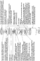
Fig. 3 is an assembly flow chart. -
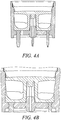
Fig. 4A is an enlarged side sectional view of the supporting table. -
Fig. 4B is a further enlarged side sectional view of the vent tube. -
Fig. 5 is an exploded view of another sensor. -
Fig. 6 is an exploded view of another sensor. -
Fig. 7 is an enlarged view of a support table. -
Fig. 8 is an enlarged view of a body. -
Fig. 9 is an enlarged view of a cross-section of the body. -
Fig. 10 is an enlarged view of a vent component of a gas sensor. - While disclosed embodiments can take many different forms, specific embodiments hereof are shown in the drawings and will be described herein in detail with the understanding that the present disclosure is to be considered as an exemplification of the principles hereof, as well as the best mode of practicing same, and is not intended to limit the claims hereof to the specific embodiment illustrated.
- The subject matter hereof provides a sensor having a two piece molding, comprising an existing main body containing terminal pins, a gas inlet port or hole in the base, and an internally fitted 'table', which supports the electrode stack assembly. The table has a hollow central leg, which is sealed into the sensor body with an epoxy, whose primary purpose is to prevent egress of electrolyte via the inserted terminal pins. Another purpose of the epoxy is to prevent corrosion of the pins, which can generate currents and will eventually make leakage more likely. The epoxy also serves to hold the table legs in place. The table's hollow central leg also supports the electrode stack assembled on top of it. One useful aspect of this design is that the use of PTFE counter tape promotes quick equalization of sensor interior pressure with the atmospheric pressure outside the sensor, greatly reducing the possibility of the sensor 'glitching'. Those of skill will understand how to select the grade of such tape.
- The 'table' is an injection molded item. The molded sensor initially has at least one current collector or wires welded to the top of the terminal pins. Epoxy is then dispensed into the base of the sensor body, covering the internal base of the sensor and the top of the terminal pins. The gas inlet port is a protrusion in the center of the base and sits above the height of the epoxy, so that the epoxy does not leak out of the sensor body molding during curing and to ensure that the epoxy does not get into the vent and obscure the hole.
- The table is then added to this epoxy before the epoxy has cured. The table sits over the protrusion in the center of the base of the molding, and the epoxy is allowed to cure. The epoxy is exothermic, but curing time is decreased by passing through an oven. This also promotes a drop in viscosity of the epoxy, which ensures that it flows around the table leg and seals it in place.
- The lower viscosity also ensures the table settles correctly onto the floor of the sensor body molding, although a tight fitting table to sensor body protrusion also promotes positive, consistent location. In this way, a gas pathway has been created from the exterior base of the sensor body up to the bottom the electrode stack, which is situated at the top of the sensor body.
- In one embodiment, the sensor comprises a body having at least one terminal pin connected to at least one current collector, and a gas inlet port, a table with a gas inlet port in alignment with the gas inlet port of the body, at least one leg seated on the body near the at least one terminal pin, a vent membrane carried on the table, a counter electrode carried on the vent membrane, a reference electrode in communication with but separated from the counter electrode by at least one washer or pad, a sensing electrode in communication with but separated from the reference electrode by at least one washer or pad, and a cap on top of the sensing electrode, which cap attaches to the body and forms a seal to contain an enclosed electrolyte.
- In another embodiment, the sensor comprises a housing, at least two electrodes, an electrolyte, and at least one separator, wherein the at least one separator includes polychlorotrifluoroethylene.
- In yet another embodiment, the sensor comprises an electrode stack including at least a sensing electrode and a counter electrode; electrolyte between the electrodes; a table which carries the electrode stack; a housing, which carries the electrolyte and the table, wherein the table provides a venting route connecting a selected region of the stack to an outside surface of the housing.
- In still yet another embodiment, the sensor comprises a housing, at least two electrodes, an electrolyte, and a vent membrane in communication with a vent leading to an external atmosphere.
- The Figures illustrate aspects of the embodiments hereof.
Fig. 1 illustrates an exploded view of a sensor in accordance herewith.Figs. 2A, 2B illustrates details of a support table epoxied into a sensor body enclosure.Fig. 3 illustrates a sensor assembly process.Figs 4A, 4B illustrate additional aspects of a support table.Fig. 5 illustrates an exploded view of another sensor.Fig. 6 illustrates an exploded view of yet another sensor.Fig. 7 is an enlarged view of a support table.Fig. 8 is an enlarged view of a body.Fig. 9 is an enlarged view of a cross-section of the body.Fig. 10 is an enlarged view of a vent component of a gas sensor. -
Figure 5 refers to the general assembly of one embodiment of anoxygen sensor 10. Starting at the lower end of thesensor 10, there is abody 40, which can be molded from plastic or any inert material. Thebody 40 has at least oneterminal pin 42, which has a platinum current collector (not shown) connected to the top of theterminal pin 42. The at least one current collector runs along the inner wall(s) of the body. In one embodiment, the body has three terminal pins with a corresponding number of current collectors attached to them. Thebody 40 can optionally have a label on the outer surface. There is an inlet port or hole (not shown) on thebody 40 where gas can enter and travel through. The gas inlet port of the body can be a hollow protrusion. Thebody 40 has a cavity that can contain anelectrolyte 38, which can be added via an access hole that is heat-sealed afterelectrolyte 38 has been added. - Attached to the
body 40 is a support table 46 having a gas inlet port in alignment with the gas inlet port of the body, and three legs attached to the perimeter of the body wherein the legs are located near the terminal pins of the body. The gas inlet port of the table can be a central, hollow leg on the same side of the table as the other table legs. The raised protrusion inlet port in the center of the body can snap into the central, hollow leg of the table. In one embodiment, theoxygen sensor 10 has three current collectors and the table 46 has three legs. The perimeter legs of the table have cut-out sections at the bottom of the feet where the current collector(s) can travel under to reach the inner wall(s) of the body. Epoxy (not shown) is dispensed over the tops of thepins 42 causing a seal to be made around thepins 42 so thatelectrolyte 38 cannot leak around these components. The epoxy also flows into any possible gaps that may be present between the legs of the table 46 and thebody 40. - A
carbon cloth disk 36 is located on the top surface of the table 46. Thecarbon cloth disk 36 may be secured to the top surface of the table 46 by adhesive. Optionally, the top of the table 46 may contain a recess for thedisk 36 to be seated. On top of thecarbon cloth disk 36 is avent membrane 34, which can be made of polytetrafluoroethylene (PTFE). Thevent membrane 34 has at least one tab along the perimeter of themembrane 34, which protrudes from the bottom of themembrane 34. Two tabs are shown but there may be more or less than two. Thevent membrane 34 can be heat-sealed over thecarbon cloth disk 36 to preventelectrolyte 38 leakage. Placed above thevent membrane 34 is acounter electrode 32, which is seated upon a section ofPTFE tape 48. Thevent membrane 34 and the section ofPTFE tape 48 upon which thecounter electrode 32 sits are in intimate contact. Equalization of air pressure within thesensor 10 is achieved by the tabs on both the PTFE tape section and thevent membrane 34. ThePTFE tape 48 is gas permeable. Apad 50 is located on top of thecounter electrode 32. The pad can be made of glass fiber. Thepad 50 can optionally have tabs along its diameter protruding from its bottom surface. Awasher separator 30 is located on top of thepad 50. Thewasher separator 30 can be made of glass fiber. - There is a
gas barrier 12 located on top of thewasher separator 30 or within the opening of thewasher separator 30. Thegas barrier 12 can be made of polychlorotrifluoroethylene (PCTFE), as in Aclar® film or Hydroblock® film. Aclar® film can be used as a gas barrier in many gas sensor devices. Areference electrode 52 is located on top of thegas barrier 12. Aseparator 14 is added on top of thereference electrode 52. Agas barrier 54 is placed on top of theseparator 14. Thegas barrier 54 can be made of PCTFE, as in Aclar® film or Hydroblock® film. Optionally, thegas barrier 54 can be in the shape of a square to ensure that the separators above it will remain wetted and still be allowed to communicate electrochemically. Above thegas barrier 54 is anotherseparator 16, which can be made of glass fiber. Awasher separator 56, which can be made of glass fiber, is situated on top of theseparator 16. Asensing electrode 18 is on top of thewasher separator 56. Adiffuser 28 is located on top of thesensing electrode 18. Thediffuser 28 is placed in a recess on the underneath of acap 20. The sensing electrode is heat-sealed into place on thecap 20, which also serves to preventelectrolyte 38 leakage. After assembly of these components, thecap 20 is placed onto thebody 40 and is sealed. The sealing can be accomplished by ultrasonic welding in one embodiment. Anadhesive ring 26 is placed on the surface of thecap 20, which surrounds a capillary located in the center of thecap 20. Abulk flow assembly 22 is added on top of theadhesive ring 26. A meshouter cover 24 can be added to the top of thebulk flow assembly 22. The dashed lines represent current collectors, which run up the inside of the stack of components along the wall of thebody 40. -
Figure 6 refers to the general assembly of one embodiment of anoxygen sensor 10. Starting at the lower end of thesensor 10, there is abody 40, which can be molded from plastic or any inert material. Thebody 40 has at least oneterminal pin 42, which has a platinum current collector (not shown) attached to the top of theterminal pin 42. The at least one current collector runs along the inner wall(s) of the body. In one embodiment, the body has three terminal pins with a corresponding number of current collectors attached to them. Thebody 40 can optionally have a label on the outer surface. There is an inlet port or hole (not shown) on thebody 40 where gas can enter and travel through. The gas inlet port of the body can be a hollow protrusion. Thebody 40 has a cavity that can contain anelectrolyte 38, which can be added via an access hole that is heat-sealed afterelectrolyte 38 has been added. - Attached on the top of the
body 40 is a table 46 having a gas inlet port in alignment with the gas inlet port of the body, and at least one leg attached to the perimeter of the body, wherein the leg(s) are located near the terminal pins. The gas inlet port of the table can be a central, hollow leg on the same side of the table as the other leg(s). The raised protrusion inlet port in the center of the body can snap into the central, hollow leg of the table. In one embodiment, theoxygen sensor 10 has three current collectors and the table 46, correspondingly has three legs attached to the perimeter of the body. The perimeter legs of the table have cut-out sections at the bottom of the feet where the current collectors can travel under to reach the inner wall(s) of the body. Epoxy (not shown) is dispensed over the tops of thepins 42 causing a seal to be made around thepins 42 so thatelectrolyte 38 cannot leak around these components. The epoxy also flows into any possible gaps that may be present between the legs of the table 46 and thebody 40. - A
carbon cloth disk 36 is located on the top surface of the table 46. Thecarbon cloth disk 36 may be secured to the top surface of the table 46 by adhesive. Optionally, the top of the table 46 may contain a recess for thedisk 36 to be seated. On top of the carbon disk is acounter electrode 32, which is seated upon a section ofPTFE tape 48. The tape has at least one tab along the perimeter and protrudes from the bottom. Equalization of air pressure within thesensor 10 is achieved by the tabs on thePTFE tape section 48, which is gas permeable. Apad 50 is located on top of thecounter electrode 32. The pad can be made of glass fiber. There is agas barrier 12 located on top of thepad 50. Thegas barrier 12 can be made of polychlorotrifluoroethylene (PCTFE), as in Aclar® film or Hydroblock® film. Areference electrode 52 is located on top of thegas barrier 12. Awasher 30 is added on top of thereference electrode 52. Aseparator 14 is placed on top of thewasher 30. Agas barrier 54 is placed on top of theseparator 14. Thegas barrier 54 can be made of PCTFE, as in Aclar® film or Hydroblock® film. Optionally, thegas barrier 54 can be in the shape of a square to ensure that the separators above it will remain wetted and still be allowed to communicate electrochemically. Above thegas barrier 54 is anotherseparator 16, which can be made of glass fiber. Awasher separator 56, which can be made of glass fiber, is situated on top of theseparator 16. Asensing electrode 18 is on top of thewasher separator 56. Adiffuser 28 is located on top of thesensing electrode 18. Thediffuser 28 is placed in a recess on the underneath of acap 20. The sensing electrode is heat-sealed into place on thecap 20, which also serves to preventelectrolyte 38 leakage. After assembly of these components, thecap 20 is placed onto thebody 40 and is sealed. The sealing can be accomplished by ultrasonic welding in one embodiment. Anadhesive ring 26 is placed on the surface of thecap 20, which surrounds a capillary located in the center of thecap 20. Abulk flow assembly 22 is added on top of theadhesive ring 26. A meshouter cover 24 can be added to the top of thebulk flow assembly 22. The dashed lines in the Figure represent current collectors (not shown), which run up the inside of the stack of components along the wall of thebody 40. - It is known that electrochemical gas sensors contain a significant volume of internal "free space" within the housing that is filled with air throughout the majority of the operational lifetime of the sensor. As the sensor housing is typically sealed to prevent release of electrolyte, air remains trapped within the sensor and that air can be affected by changes in local environmental conditions (specifically temperature and pressure) as described by the "gas laws". Pressure differentials between the atmosphere in the sensor and that outside the sensor can disrupt the performance of the device. The present gas sensor provides a route that links the internal and external atmospheres, as exemplified here by the path from the electrode stack through the table support to the external vent. This path provides sufficiently low flow resistance to ensure that pressure equalizes quickly under all operating conditions. Moreover, all spaces within the sensor requiring venting are intimately linked, noting that their position can be affected by sensor orientation and external forces such as vibration and shock. This can be problematic when inert, porous polymers (e.g. polypropylene or PTFE) are used as vents since sealing by means of thermal welding or compression (e.g. using 'O' rings) can critically restrict the material porosity. The present gas sensor incorporates a porous vent component and seals it to the enclosure without the sealing mechanism critically affecting the vent functionality.
- The vent component (
Fig. 10 ) of the present gas sensor employs two PTFE tapes with different material properties to separate the differing aspects of the functionality. High water ingress pressure (WIP) PTFE can affect a robust seal and the low WIP PTFE can affect a robust lateral vent that can access many pockets of gas within the sensor enclosure, using a "tabbed / winged" component geometry as shown, the section ofPTFE tape 48, inFig. 6 . A disc of high WIP PTFE tape is heat sealed over a vent hole and allows sufficient air to flow through (perpendicular to the sheet plane) it to prevent undesirably high pressure differentials between the internal and external environments. A low WIP, high porosity PTFE tape is then laid across and held in intimate contact with the disc of high WIP PTFE tape so that lateral (in sheet plane) diffusion rate of air flow within the low WIP, high porosity PTFE is sufficiently high to effectively vent air between the internal and external environments. Low WIP, high porosity PTFE is also compatible with electrode deposition onto its surface. - A strong, high WIP porous PTFE tape, grade 6 thou natural, manufactured by GORE® or Mupor high WIP can be used to provide the seal. The venting capability of this material has previously been demonstrated and importantly it forms a robust seal to the Noryl® engineering plastic used in the housing and is strong enough to be handled in production processes. Mupor PTFE tape, Grade PM17Y, can be used as the counter electrode tape.
- From the foregoing, it will be observed that numerous variations and modifications may be effected without departing from the spirit and scope of the invention. It is to be understood that no limitation with respect to the specific apparatus illustrated herein is intended or should be inferred. It is, of course, intended to cover by the appended claims all such modifications as fall within the scope of the claims.
- Further, logic flows depicted in the figures do not require the particular order shown, or sequential order, to achieve desirable results. Other steps may be provided, or steps may be eliminated, from the described flows, and other components may be add to, or removed from the described embodiments.
Claims (11)
- A sensor (10) comprising:a molded body having an internal cavity comprising at least one terminal pin (42), at least one current collector connected to the at least one terminal pin, and a gas inlet port comprising a protrusion in the center of the body;a fitted table (46) attached inside the internal cavity of the body with epoxy, the table comprising a hollow central leg, and a gas inlet port in alignment with the gas inlet port of the body, wherein the hollow central leg sits over and is configured to snap into the protrusion of the gas inlet port of the body;a vent membrane (34) carried on the table wherein the vent membrane comprises a tab thathangs into the body;a counter electrode (32) carried on the vent membrane;at least one first washer or pad (48) carried on the counter electrode;a wick (50) carried on the one first washer or pad;a reference electrode (52) in communication with but separated from the counter electrode by the at least one first washer or pad;at least one second washer or pad (56);a sensing electrode (18) in communication with but separated from the reference electrode by the at least one second washer or pad; anda cap (20) on top of the sensing electrode, which cap attaches to the body and forms a seal to contain an enclosed electrolyte.
- The sensor of claim 1 further comprising a carbon cloth between the table and the vent membrane.
- The sensor of claim 1 wherein the vent membrane comprises polytetrafluoroethylene.
- The sensor of claim 1 wherein the counter electrode is seated upon a section of polytetrafluoroethylene tape.
- The sensor of claim 1 further comprising a gas barrier on top of the washer separator between the counter electrode and the reference electrode.
- The sensor of claim 5 wherein the gas barrier comprises polychlorotrifluoroethylene.
- The sensor of claim 1 further comprising a separator between the reference electrode and the sensing electrode wherein the separator lies on top of the reference electrode.
- The sensor of claim 1 further comprising a gas barrier between the reference electrode and the sensing electrode wherein the gas barrier lies on top of the separator.
- The sensor of claim 1 further comprising a diffuser on top of the sensing electrode.
- The sensor of claim 1 further comprising an adhesive ring on the surface of the cap.
- The sensor of claim 1 further comprising a bulk flow assembly, which lies on top of the adhesive ring.
Applications Claiming Priority (2)
| Application Number | Priority Date | Filing Date | Title |
|---|---|---|---|
| US201361900669P | 2013-11-06 | 2013-11-06 | |
| US14/506,312 US9874540B2 (en) | 2013-11-06 | 2014-10-03 | Support for electrode stack and provision for venting of a gas sensor using an internally mounted table |
Publications (2)
| Publication Number | Publication Date |
|---|---|
| EP2871472A1 EP2871472A1 (en) | 2015-05-13 |
| EP2871472B1 true EP2871472B1 (en) | 2017-03-01 |
Family
ID=51730383
Family Applications (1)
| Application Number | Title | Priority Date | Filing Date |
|---|---|---|---|
| EP14188914.7A Active EP2871472B1 (en) | 2013-11-06 | 2014-10-14 | Support for electrode stack and provision for venting of a gas sensor using an internally mounted table |
Country Status (3)
| Country | Link |
|---|---|
| US (1) | US9874540B2 (en) |
| EP (1) | EP2871472B1 (en) |
| CN (1) | CN104634835B (en) |
Families Citing this family (10)
| Publication number | Priority date | Publication date | Assignee | Title |
|---|---|---|---|---|
| WO2017014764A1 (en) * | 2015-07-22 | 2017-01-26 | Honeywell International Inc. | Inert corrosion barriers for current collector protection |
| WO2017014851A1 (en) * | 2015-07-22 | 2017-01-26 | Honeywell International Inc. | One piece shaped planar separator |
| EP3408660B1 (en) * | 2016-01-29 | 2023-01-18 | Honeywell International Inc. | Electrochemical gas sensor |
| CN105651839B (en) * | 2016-03-22 | 2018-12-25 | 湖北大学 | Three-electrode reactor and its application |
| EP3555610B1 (en) * | 2016-12-19 | 2023-04-19 | Honeywell International Inc. | Method of pressure equalization in gas detector as well as corresponding gas detector |
| US10732141B2 (en) * | 2017-02-15 | 2020-08-04 | InSyte Systems | Electrochemical gas sensor system with improved accuracy and speed |
| CN111380936B (en) * | 2018-12-29 | 2024-06-18 | 霍尼韦尔国际公司 | Electrochemical Gas Sensor Components |
| CN216082584U (en) * | 2021-06-11 | 2022-03-18 | 清华大学 | Solid electrolyte three-electrode electrochemical testing device |
| DE102021116238A1 (en) * | 2021-06-23 | 2022-12-29 | Testo SE & Co. KGaA | Electrochemical gas sensor |
| DE102024105481A1 (en) * | 2024-02-27 | 2025-08-28 | Endress+Hauser Conducta Gmbh+Co. Kg | Sensor cap for a sensor and manufacturing method of the sensor cap |
Family Cites Families (13)
| Publication number | Priority date | Publication date | Assignee | Title |
|---|---|---|---|---|
| US4042464A (en) * | 1975-10-10 | 1977-08-16 | Energetics Science, Inc. | Method for the detection and measurement of noxious gases |
| US4477403A (en) * | 1983-05-26 | 1984-10-16 | Teledyne Industries, Inc. | Method of making an electrochemical sensor |
| US5284566A (en) * | 1993-01-04 | 1994-02-08 | Bacharach, Inc. | Electrochemical gas sensor with wraparound reference electrode |
| US5338429A (en) | 1993-03-05 | 1994-08-16 | Mine Safety Appliances Company | Electrochemical toxic gas sensor |
| GB2303710A (en) | 1993-03-05 | 1997-02-26 | Mine Safety Appliances Co | Electrochemical toxic gas sensor with gas permeable membrane |
| CH686981A5 (en) | 1994-02-09 | 1996-08-15 | Christian Dr Huggenberger | Ammonia sensor. |
| GB0329103D0 (en) * | 2003-12-16 | 2004-01-21 | Alphasense Ltd | Electrochemical sensor |
| CH697047A5 (en) | 2004-05-27 | 2008-03-31 | Membrapor Ag | Ammonia sensor. |
| US7582196B2 (en) * | 2004-08-16 | 2009-09-01 | General Electric Company | Laminated membranes for diffusion limited gas sensors resistant to pressure variations |
| US20060257288A1 (en) * | 2005-05-03 | 2006-11-16 | Teledyne Technologies Incorporated | Hydrogen sulfide tolerant oxygen gas sensing device |
| US20070170056A1 (en) | 2006-01-26 | 2007-07-26 | Arnold Don W | Microscale electrochemical cell and methods incorporating the cell |
| JP5838163B2 (en) | 2009-10-30 | 2015-12-24 | エムエスエー テクノロジー, リミテッド・ライアビリティ・カンパニー | Electrochemical gas sensor comprising an electrode with a diffusion barrier, electrode assembly and method for restricting gas transport through a diffusion barrier |
| US9689833B2 (en) | 2011-10-11 | 2017-06-27 | Life Safety Distribution Ag | Auxiliary micro-electrodes for diagnostics of electrochemical gas sensors |
-
2014
- 2014-10-03 US US14/506,312 patent/US9874540B2/en active Active
- 2014-10-14 EP EP14188914.7A patent/EP2871472B1/en active Active
- 2014-11-05 CN CN201410614877.XA patent/CN104634835B/en active Active
Non-Patent Citations (1)
| Title |
|---|
| None * |
Also Published As
| Publication number | Publication date |
|---|---|
| CN104634835B (en) | 2018-04-24 |
| US20150122649A1 (en) | 2015-05-07 |
| US9874540B2 (en) | 2018-01-23 |
| CN104634835A (en) | 2015-05-20 |
| EP2871472A1 (en) | 2015-05-13 |
Similar Documents
| Publication | Publication Date | Title |
|---|---|---|
| US9874540B2 (en) | Support for electrode stack and provision for venting of a gas sensor using an internally mounted table | |
| US9151729B2 (en) | Carbon monoxide sensor system | |
| CN102636542B (en) | Gas sensor | |
| US11994490B2 (en) | Electrochemical gas sensor assembly | |
| JP6077749B2 (en) | Vented oxygen battery | |
| CN106461597A (en) | Electrochemical cell | |
| EP2498085A2 (en) | Low water vapour transfer coating of thermoplastic moulded oxygen gas sensors | |
| CN104067441B (en) | Air cell and the battery pack using the air cell | |
| US7935234B2 (en) | Electrochemical gas sensor and process for manufacturing same | |
| CN102851681A (en) | Self-breathing electrochemical oxygenerator | |
| CN105246578B (en) | Gas permeable member, the manufacture method of gas permeable member and permeable container | |
| CN114965648A (en) | oxygen sensor | |
| JP2015170468A (en) | Gas permeable member, gas permeable member inspection method and breathable container | |
| JP4463145B2 (en) | Electrochemical gas sensor and manufacturing method thereof | |
| CN212410498U (en) | Hydrogen sensor | |
| CN223513179U (en) | Packaging device of electrochemical sensor | |
| US7060652B2 (en) | Gas sensor | |
| EP3555610B1 (en) | Method of pressure equalization in gas detector as well as corresponding gas detector | |
| CN110967387A (en) | Hydrogen sensor | |
| JP4164401B2 (en) | Constant-potential electrolysis gas sensor | |
| JP2005061991A (en) | Constant-potential electrolysis gas sensor | |
| CN216696147U (en) | Electrochemical gas sensor with inlet and outlet interface | |
| CN223816999U (en) | Electronic atomization devices | |
| JP2012085600A (en) | Electric culture apparatus | |
| JP2004205423A (en) | Constant potential electrolysis type gas sensor |
Legal Events
| Date | Code | Title | Description |
|---|---|---|---|
| PUAI | Public reference made under article 153(3) epc to a published international application that has entered the european phase |
Free format text: ORIGINAL CODE: 0009012 |
|
| 17P | Request for examination filed |
Effective date: 20141014 |
|
| AK | Designated contracting states |
Kind code of ref document: A1 Designated state(s): AL AT BE BG CH CY CZ DE DK EE ES FI FR GB GR HR HU IE IS IT LI LT LU LV MC MK MT NL NO PL PT RO RS SE SI SK SM TR |
|
| AX | Request for extension of the european patent |
Extension state: BA ME |
|
| GRAP | Despatch of communication of intention to grant a patent |
Free format text: ORIGINAL CODE: EPIDOSNIGR1 |
|
| RIC1 | Information provided on ipc code assigned before grant |
Ipc: G01N 27/403 20060101ALI20160610BHEP Ipc: G01N 27/404 20060101AFI20160610BHEP |
|
| INTG | Intention to grant announced |
Effective date: 20160628 |
|
| GRAJ | Information related to disapproval of communication of intention to grant by the applicant or resumption of examination proceedings by the epo deleted |
Free format text: ORIGINAL CODE: EPIDOSDIGR1 |
|
| GRAS | Grant fee paid |
Free format text: ORIGINAL CODE: EPIDOSNIGR3 |
|
| GRAP | Despatch of communication of intention to grant a patent |
Free format text: ORIGINAL CODE: EPIDOSNIGR1 |
|
| INTC | Intention to grant announced (deleted) | ||
| INTG | Intention to grant announced |
Effective date: 20161018 |
|
| GRAA | (expected) grant |
Free format text: ORIGINAL CODE: 0009210 |
|
| AK | Designated contracting states |
Kind code of ref document: B1 Designated state(s): AL AT BE BG CH CY CZ DE DK EE ES FI FR GB GR HR HU IE IS IT LI LT LU LV MC MK MT NL NO PL PT RO RS SE SI SK SM TR |
|
| REG | Reference to a national code |
Ref country code: GB Ref legal event code: FG4D |
|
| REG | Reference to a national code |
Ref country code: CH Ref legal event code: EP Ref country code: AT Ref legal event code: REF Ref document number: 871950 Country of ref document: AT Kind code of ref document: T Effective date: 20170315 |
|
| REG | Reference to a national code |
Ref country code: IE Ref legal event code: FG4D |
|
| REG | Reference to a national code |
Ref country code: DE Ref legal event code: R096 Ref document number: 602014007079 Country of ref document: DE |
|
| REG | Reference to a national code |
Ref country code: NL Ref legal event code: MP Effective date: 20170301 |
|
| REG | Reference to a national code |
Ref country code: LT Ref legal event code: MG4D |
|
| REG | Reference to a national code |
Ref country code: AT Ref legal event code: MK05 Ref document number: 871950 Country of ref document: AT Kind code of ref document: T Effective date: 20170301 |
|
| PG25 | Lapsed in a contracting state [announced via postgrant information from national office to epo] |
Ref country code: GR Free format text: LAPSE BECAUSE OF FAILURE TO SUBMIT A TRANSLATION OF THE DESCRIPTION OR TO PAY THE FEE WITHIN THE PRESCRIBED TIME-LIMIT Effective date: 20170602 Ref country code: LT Free format text: LAPSE BECAUSE OF FAILURE TO SUBMIT A TRANSLATION OF THE DESCRIPTION OR TO PAY THE FEE WITHIN THE PRESCRIBED TIME-LIMIT Effective date: 20170301 Ref country code: NO Free format text: LAPSE BECAUSE OF FAILURE TO SUBMIT A TRANSLATION OF THE DESCRIPTION OR TO PAY THE FEE WITHIN THE PRESCRIBED TIME-LIMIT Effective date: 20170601 Ref country code: FI Free format text: LAPSE BECAUSE OF FAILURE TO SUBMIT A TRANSLATION OF THE DESCRIPTION OR TO PAY THE FEE WITHIN THE PRESCRIBED TIME-LIMIT Effective date: 20170301 Ref country code: HR Free format text: LAPSE BECAUSE OF FAILURE TO SUBMIT A TRANSLATION OF THE DESCRIPTION OR TO PAY THE FEE WITHIN THE PRESCRIBED TIME-LIMIT Effective date: 20170301 |
|
| PG25 | Lapsed in a contracting state [announced via postgrant information from national office to epo] |
Ref country code: SE Free format text: LAPSE BECAUSE OF FAILURE TO SUBMIT A TRANSLATION OF THE DESCRIPTION OR TO PAY THE FEE WITHIN THE PRESCRIBED TIME-LIMIT Effective date: 20170301 Ref country code: AT Free format text: LAPSE BECAUSE OF FAILURE TO SUBMIT A TRANSLATION OF THE DESCRIPTION OR TO PAY THE FEE WITHIN THE PRESCRIBED TIME-LIMIT Effective date: 20170301 Ref country code: LV Free format text: LAPSE BECAUSE OF FAILURE TO SUBMIT A TRANSLATION OF THE DESCRIPTION OR TO PAY THE FEE WITHIN THE PRESCRIBED TIME-LIMIT Effective date: 20170301 Ref country code: ES Free format text: LAPSE BECAUSE OF FAILURE TO SUBMIT A TRANSLATION OF THE DESCRIPTION OR TO PAY THE FEE WITHIN THE PRESCRIBED TIME-LIMIT Effective date: 20170301 Ref country code: BG Free format text: LAPSE BECAUSE OF FAILURE TO SUBMIT A TRANSLATION OF THE DESCRIPTION OR TO PAY THE FEE WITHIN THE PRESCRIBED TIME-LIMIT Effective date: 20170601 Ref country code: RS Free format text: LAPSE BECAUSE OF FAILURE TO SUBMIT A TRANSLATION OF THE DESCRIPTION OR TO PAY THE FEE WITHIN THE PRESCRIBED TIME-LIMIT Effective date: 20170301 |
|
| PG25 | Lapsed in a contracting state [announced via postgrant information from national office to epo] |
Ref country code: NL Free format text: LAPSE BECAUSE OF FAILURE TO SUBMIT A TRANSLATION OF THE DESCRIPTION OR TO PAY THE FEE WITHIN THE PRESCRIBED TIME-LIMIT Effective date: 20170301 |
|
| PG25 | Lapsed in a contracting state [announced via postgrant information from national office to epo] |
Ref country code: EE Free format text: LAPSE BECAUSE OF FAILURE TO SUBMIT A TRANSLATION OF THE DESCRIPTION OR TO PAY THE FEE WITHIN THE PRESCRIBED TIME-LIMIT Effective date: 20170301 Ref country code: RO Free format text: LAPSE BECAUSE OF FAILURE TO SUBMIT A TRANSLATION OF THE DESCRIPTION OR TO PAY THE FEE WITHIN THE PRESCRIBED TIME-LIMIT Effective date: 20170301 Ref country code: SK Free format text: LAPSE BECAUSE OF FAILURE TO SUBMIT A TRANSLATION OF THE DESCRIPTION OR TO PAY THE FEE WITHIN THE PRESCRIBED TIME-LIMIT Effective date: 20170301 Ref country code: CZ Free format text: LAPSE BECAUSE OF FAILURE TO SUBMIT A TRANSLATION OF THE DESCRIPTION OR TO PAY THE FEE WITHIN THE PRESCRIBED TIME-LIMIT Effective date: 20170301 Ref country code: IT Free format text: LAPSE BECAUSE OF FAILURE TO SUBMIT A TRANSLATION OF THE DESCRIPTION OR TO PAY THE FEE WITHIN THE PRESCRIBED TIME-LIMIT Effective date: 20170301 |
|
| REG | Reference to a national code |
Ref country code: FR Ref legal event code: PLFP Year of fee payment: 4 |
|
| PG25 | Lapsed in a contracting state [announced via postgrant information from national office to epo] |
Ref country code: PL Free format text: LAPSE BECAUSE OF FAILURE TO SUBMIT A TRANSLATION OF THE DESCRIPTION OR TO PAY THE FEE WITHIN THE PRESCRIBED TIME-LIMIT Effective date: 20170301 Ref country code: SM Free format text: LAPSE BECAUSE OF FAILURE TO SUBMIT A TRANSLATION OF THE DESCRIPTION OR TO PAY THE FEE WITHIN THE PRESCRIBED TIME-LIMIT Effective date: 20170301 Ref country code: IS Free format text: LAPSE BECAUSE OF FAILURE TO SUBMIT A TRANSLATION OF THE DESCRIPTION OR TO PAY THE FEE WITHIN THE PRESCRIBED TIME-LIMIT Effective date: 20170701 Ref country code: PT Free format text: LAPSE BECAUSE OF FAILURE TO SUBMIT A TRANSLATION OF THE DESCRIPTION OR TO PAY THE FEE WITHIN THE PRESCRIBED TIME-LIMIT Effective date: 20170703 |
|
| REG | Reference to a national code |
Ref country code: DE Ref legal event code: R097 Ref document number: 602014007079 Country of ref document: DE |
|
| PLBE | No opposition filed within time limit |
Free format text: ORIGINAL CODE: 0009261 |
|
| STAA | Information on the status of an ep patent application or granted ep patent |
Free format text: STATUS: NO OPPOSITION FILED WITHIN TIME LIMIT |
|
| PG25 | Lapsed in a contracting state [announced via postgrant information from national office to epo] |
Ref country code: DK Free format text: LAPSE BECAUSE OF FAILURE TO SUBMIT A TRANSLATION OF THE DESCRIPTION OR TO PAY THE FEE WITHIN THE PRESCRIBED TIME-LIMIT Effective date: 20170301 |
|
| 26N | No opposition filed |
Effective date: 20171204 |
|
| PG25 | Lapsed in a contracting state [announced via postgrant information from national office to epo] |
Ref country code: SI Free format text: LAPSE BECAUSE OF FAILURE TO SUBMIT A TRANSLATION OF THE DESCRIPTION OR TO PAY THE FEE WITHIN THE PRESCRIBED TIME-LIMIT Effective date: 20170301 |
|
| PG25 | Lapsed in a contracting state [announced via postgrant information from national office to epo] |
Ref country code: MC Free format text: LAPSE BECAUSE OF FAILURE TO SUBMIT A TRANSLATION OF THE DESCRIPTION OR TO PAY THE FEE WITHIN THE PRESCRIBED TIME-LIMIT Effective date: 20170301 |
|
| REG | Reference to a national code |
Ref country code: CH Ref legal event code: PL |
|
| REG | Reference to a national code |
Ref country code: IE Ref legal event code: MM4A |
|
| PG25 | Lapsed in a contracting state [announced via postgrant information from national office to epo] |
Ref country code: LI Free format text: LAPSE BECAUSE OF NON-PAYMENT OF DUE FEES Effective date: 20171031 Ref country code: LU Free format text: LAPSE BECAUSE OF NON-PAYMENT OF DUE FEES Effective date: 20171014 Ref country code: CH Free format text: LAPSE BECAUSE OF NON-PAYMENT OF DUE FEES Effective date: 20171031 |
|
| REG | Reference to a national code |
Ref country code: BE Ref legal event code: MM Effective date: 20171031 |
|
| PG25 | Lapsed in a contracting state [announced via postgrant information from national office to epo] |
Ref country code: BE Free format text: LAPSE BECAUSE OF NON-PAYMENT OF DUE FEES Effective date: 20171031 |
|
| PG25 | Lapsed in a contracting state [announced via postgrant information from national office to epo] |
Ref country code: MT Free format text: LAPSE BECAUSE OF NON-PAYMENT OF DUE FEES Effective date: 20171014 |
|
| REG | Reference to a national code |
Ref country code: FR Ref legal event code: PLFP Year of fee payment: 5 |
|
| PG25 | Lapsed in a contracting state [announced via postgrant information from national office to epo] |
Ref country code: IE Free format text: LAPSE BECAUSE OF NON-PAYMENT OF DUE FEES Effective date: 20171014 |
|
| PG25 | Lapsed in a contracting state [announced via postgrant information from national office to epo] |
Ref country code: HU Free format text: LAPSE BECAUSE OF FAILURE TO SUBMIT A TRANSLATION OF THE DESCRIPTION OR TO PAY THE FEE WITHIN THE PRESCRIBED TIME-LIMIT; INVALID AB INITIO Effective date: 20141014 |
|
| PG25 | Lapsed in a contracting state [announced via postgrant information from national office to epo] |
Ref country code: CY Free format text: LAPSE BECAUSE OF FAILURE TO SUBMIT A TRANSLATION OF THE DESCRIPTION OR TO PAY THE FEE WITHIN THE PRESCRIBED TIME-LIMIT Effective date: 20170301 |
|
| PG25 | Lapsed in a contracting state [announced via postgrant information from national office to epo] |
Ref country code: MK Free format text: LAPSE BECAUSE OF FAILURE TO SUBMIT A TRANSLATION OF THE DESCRIPTION OR TO PAY THE FEE WITHIN THE PRESCRIBED TIME-LIMIT Effective date: 20170301 |
|
| PG25 | Lapsed in a contracting state [announced via postgrant information from national office to epo] |
Ref country code: TR Free format text: LAPSE BECAUSE OF FAILURE TO SUBMIT A TRANSLATION OF THE DESCRIPTION OR TO PAY THE FEE WITHIN THE PRESCRIBED TIME-LIMIT Effective date: 20170301 |
|
| PG25 | Lapsed in a contracting state [announced via postgrant information from national office to epo] |
Ref country code: AL Free format text: LAPSE BECAUSE OF FAILURE TO SUBMIT A TRANSLATION OF THE DESCRIPTION OR TO PAY THE FEE WITHIN THE PRESCRIBED TIME-LIMIT Effective date: 20170301 |
|
| PGFP | Annual fee paid to national office [announced via postgrant information from national office to epo] |
Ref country code: DE Payment date: 20251028 Year of fee payment: 12 |
|
| PGFP | Annual fee paid to national office [announced via postgrant information from national office to epo] |
Ref country code: GB Payment date: 20251023 Year of fee payment: 12 |
|
| PGFP | Annual fee paid to national office [announced via postgrant information from national office to epo] |
Ref country code: FR Payment date: 20251027 Year of fee payment: 12 |