EP2871467A1 - Bearing part inspection method and bearing part inspection device - Google Patents
Bearing part inspection method and bearing part inspection device Download PDFInfo
- Publication number
- EP2871467A1 EP2871467A1 EP13813631.2A EP13813631A EP2871467A1 EP 2871467 A1 EP2871467 A1 EP 2871467A1 EP 13813631 A EP13813631 A EP 13813631A EP 2871467 A1 EP2871467 A1 EP 2871467A1
- Authority
- EP
- European Patent Office
- Prior art keywords
- bearing part
- rays
- inspected
- use condition
- fatigued portion
- Prior art date
- Legal status (The legal status is an assumption and is not a legal conclusion. Google has not performed a legal analysis and makes no representation as to the accuracy of the status listed.)
- Granted
Links
- 238000007689 inspection Methods 0.000 title claims abstract description 69
- 238000000034 method Methods 0.000 title claims abstract description 40
- 229910001566 austenite Inorganic materials 0.000 claims description 12
- 238000002441 X-ray diffraction Methods 0.000 abstract description 21
- 238000005096 rolling process Methods 0.000 description 46
- 238000003384 imaging method Methods 0.000 description 20
- 239000003921 oil Substances 0.000 description 12
- 238000004364 calculation method Methods 0.000 description 10
- 238000001514 detection method Methods 0.000 description 9
- 238000004458 analytical method Methods 0.000 description 7
- 238000005259 measurement Methods 0.000 description 6
- 238000010586 diagram Methods 0.000 description 4
- 238000009826 distribution Methods 0.000 description 4
- 238000001816 cooling Methods 0.000 description 3
- 238000005315 distribution function Methods 0.000 description 3
- 238000005461 lubrication Methods 0.000 description 3
- 238000011109 contamination Methods 0.000 description 2
- 238000007796 conventional method Methods 0.000 description 2
- 239000000463 material Substances 0.000 description 2
- 238000011160 research Methods 0.000 description 2
- 238000007619 statistical method Methods 0.000 description 2
- 238000007476 Maximum Likelihood Methods 0.000 description 1
- 229910000831 Steel Inorganic materials 0.000 description 1
- 238000013398 bayesian method Methods 0.000 description 1
- 239000013078 crystal Substances 0.000 description 1
- 230000000694 effects Effects 0.000 description 1
- 230000006870 function Effects 0.000 description 1
- 239000010687 lubricating oil Substances 0.000 description 1
- 238000004020 luminiscence type Methods 0.000 description 1
- 238000011089 mechanical engineering Methods 0.000 description 1
- 238000012986 modification Methods 0.000 description 1
- 230000004048 modification Effects 0.000 description 1
- 238000012545 processing Methods 0.000 description 1
- 239000010959 steel Substances 0.000 description 1
- XLYOFNOQVPJJNP-UHFFFAOYSA-N water Substances O XLYOFNOQVPJJNP-UHFFFAOYSA-N 0.000 description 1
Images


Classifications
-
- G—PHYSICS
- G01—MEASURING; TESTING
- G01N—INVESTIGATING OR ANALYSING MATERIALS BY DETERMINING THEIR CHEMICAL OR PHYSICAL PROPERTIES
- G01N23/00—Investigating or analysing materials by the use of wave or particle radiation, e.g. X-rays or neutrons, not covered by groups G01N3/00 – G01N17/00, G01N21/00 or G01N22/00
- G01N23/20—Investigating or analysing materials by the use of wave or particle radiation, e.g. X-rays or neutrons, not covered by groups G01N3/00 – G01N17/00, G01N21/00 or G01N22/00 by using diffraction of the radiation by the materials, e.g. for investigating crystal structure; by using scattering of the radiation by the materials, e.g. for investigating non-crystalline materials; by using reflection of the radiation by the materials
- G01N23/207—Diffractometry using detectors, e.g. using a probe in a central position and one or more displaceable detectors in circumferential positions
-
- G—PHYSICS
- G01—MEASURING; TESTING
- G01N—INVESTIGATING OR ANALYSING MATERIALS BY DETERMINING THEIR CHEMICAL OR PHYSICAL PROPERTIES
- G01N23/00—Investigating or analysing materials by the use of wave or particle radiation, e.g. X-rays or neutrons, not covered by groups G01N3/00 – G01N17/00, G01N21/00 or G01N22/00
- G01N23/20—Investigating or analysing materials by the use of wave or particle radiation, e.g. X-rays or neutrons, not covered by groups G01N3/00 – G01N17/00, G01N21/00 or G01N22/00 by using diffraction of the radiation by the materials, e.g. for investigating crystal structure; by using scattering of the radiation by the materials, e.g. for investigating non-crystalline materials; by using reflection of the radiation by the materials
-
- G—PHYSICS
- G01—MEASURING; TESTING
- G01N—INVESTIGATING OR ANALYSING MATERIALS BY DETERMINING THEIR CHEMICAL OR PHYSICAL PROPERTIES
- G01N2223/00—Investigating materials by wave or particle radiation
- G01N2223/60—Specific applications or type of materials
- G01N2223/624—Specific applications or type of materials steel, castings
-
- G—PHYSICS
- G01—MEASURING; TESTING
- G01N—INVESTIGATING OR ANALYSING MATERIALS BY DETERMINING THEIR CHEMICAL OR PHYSICAL PROPERTIES
- G01N2223/00—Investigating materials by wave or particle radiation
- G01N2223/60—Specific applications or type of materials
- G01N2223/632—Specific applications or type of materials residual life, life expectancy
Definitions
- the present invention relates to an inspection method for a bearing part and an inspection apparatus for a bearing part. More particularly, the present invention relates to an inspection method for a bearing part and an inspection apparatus for a bearing part that allow high-precision inspection of a bearing part.
- the life of a rolling bearing depends on a load applied to the bearing, a lubrication condition, a material that forms a bearing part, and the like.
- the life of the rolling bearing can be calculated by using a life calculation equation created in consideration of the aforementioned load, lubrication condition, material and the like (refer to, for example, "Dynamic Load Capacity of Rolling Bearing and Roller Bearing: Detailed Explanation of Lundberg-Palmgren Theory" (NPD 1)).
- NPD 1 Dynamic Load Capacity of Rolling Bearing and Roller Bearing: Detailed Explanation of Lundberg-Palmgren Theory
- the rolling bearing is used under a use condition set based on the life calculation equation. Therefore, as long as the rolling bearing is used under a normal condition, the life of the rolling bearing does not matter. In the market, however, there often arises a situation in which the life of the rolling bearing becomes an issue. One cause for this is considered to be that the actual use condition of the rolling bearing is different from the scheduled condition. In order to deal with such a situation, there has been proposed a method for analyzing an actually used rolling bearing and estimating the remaining life of the rolling bearing (refer to, for example, Masayuki Tsushima, Kikuo Maeda, Bearing Engineer, 48, 1984, 1-17 (NPD 2)). This method is a method using the fact that a result of stress measurement (stress, half-value width, amount of remaining austenite) with X-ray diffraction has a relation with the rolling time (operating time) of the rolling bearing.
- this method uses the relation between the stress measurement result and the rolling time under a particular rolling condition. Therefore, this method has had such a problem that this method can be applied only to a rolling bearing used under a condition close to that condition.
- the present invention has been made to solve the aforementioned problems, and an object of the present invention is to provide an inspection method and an inspection apparatus for a bearing part that allow high-precision estimation of a use condition of a rolling bearing.
- An inspection method for a bearing part includes the steps of: emitting X-rays onto a fatigued portion of a bearing part to be inspected; detecting annular diffracted X-rays diffracted by the fatigued portion; and estimating a use condition of the bearing part to be inspected, based on the detected annular diffracted X-rays.
- the X-rays are diffracted to form a conical surface, as long as the steel forming the bearing part is a polycrystalline body formed of many crystals having random orientations. Even when the X-rays are diffracted as described above, only the diffracted X-rays corresponding to one direction, of the diffracted X-rays forming the aforementioned conical surface, are detected by a detector in stress analysis for the bearing part with conventional X-ray diffraction. Then, the incidence angle is changed and the diffracted X-rays are similarly detected again, and the stress on a surface of the bearing part is calculated based on these.
- a detector having a planar detection unit is arranged at a position intersecting with all of the diffracted X-rays forming the aforementioned conical surface, and this detector detects the annular diffracted X-rays (X-ray diffraction ring) corresponding to an annular region formed by intersection of a plane including the detection unit and the aforementioned conical surface.
- This X-ray diffraction ring includes information about all of the diffracted X-rays forming the aforementioned conical surface. Therefore, the amount of information obtained in one measurement is significantly larger than that in the aforementioned conventional method. As a result, the use condition of the bearing part can be estimated with high precision. As described above, according to the inspection method for the bearing part of the present invention, the use condition of a rolling bearing can be estimated with high precision.
- the step of estimating a use condition of the bearing part to be inspected may include the steps of: deriving use condition elements including normal stress at the fatigued portion, shear stress at the fatigued portion, a relation between a central angle and an intensity of the annular diffracted X-rays, and a half-value width of a peak obtained in accordance with the central angle of the annular diffracted X-rays, based on the annular diffracted X-rays detected in the step of detecting annular diffracted X-rays; and calculating the use condition of the bearing part to be inspected, based on at least one of the derived use condition elements.
- the normal stress at the fatigued portion, the shear stress at the fatigued portion, the relation between the central angle and the intensity of the diffracted X-rays, and the half-value width of the peak obtained in accordance with the central angle of the annular diffracted X-rays have a strong correlation with the use condition of the rolling bearing. Therefore, by calculating the use condition based on these derived use condition elements, the use condition of the rolling bearing can be estimated with higher precision.
- the aforementioned inspection method for a bearing part may further include the step of evaluating a remaining life of the bearing part to be inspected, based on the use condition of the bearing part to be inspected which was calculated in the step of estimating a use condition of the bearing part to be inspected.
- the use condition elements may further include an amount of austenite remaining in the fatigued portion.
- the use condition elements may further include an amount of austenite remaining in the fatigued portion.
- the number of loading of stress applied to the fatigued portion of the bearing part to be inspected, a load applied to the fatigued portion, and an oil film parameter at the fatigued portion may be calculated based on a relation of at least any one of the normal stress at the fatigued portion, the shear stress at the fatigued portion, the amount of remaining austenite, the relation between the central angle and the intensity of the annular diffracted X-rays, and the half-value width of the peak obtained in accordance with the central angle of the annular diffracted X-rays, about the preliminarily researched bearing part, with the number of loading of stress applied to the fatigued portion of the bearing part, the load applied to the fatigued portion of the bearing part, and the oil film parameter at the fatigued portion of the bearing part.
- the relation between the use condition elements and the actual use condition (the number of loading, the load and the oil film parameter) is preliminarily researched, and the use condition is derived from the use condition elements obtained by analysis of the bearing part to be inspected. Therefore, the use condition of the rolling bearing can be estimated with high precision.
- each of the number of loading of stress applied to the fatigued portion of the bearing part to be inspected, the load applied to the fatigued portion of the bearing part to be inspected, and the oil film parameter at the fatigued portion of the bearing part to be inspected may be statistically calculated to take into consideration a relation of each of the normal stress at the fatigued portion, the shear stress at the fatigued portion, the amount of remaining austenite, the relation between the central angle and the intensity of the annular diffracted X-rays, and the half-value width of the peak obtained in accordance with the central angle of the annular diffracted X-rays, about the preliminarily researched bearing part, with all of the number of loading of stress applied to the fatigued portion of the bearing part, the load applied to the fatigued portion of the bearing part, and the oil film parameter at the fatigued portion of the bearing part.
- each use condition is not determined based on the relation with one use condition element but calculated as the most likely value based on the relation with a plurality of use condition elements. Therefore, the use condition of the rolling bearing can be estimated with higher precision.
- An inspection apparatus for a bearing part includes: an irradiation unit for emitting X-rays onto a bearing part to be inspected; a detector for detecting annular X-rays diffracted by the bearing part to be inspected; and a computation unit connected to the detector, for calculating a use condition of the bearing part to be inspected, based on the annular X-rays detected by the detector.
- the inspection apparatus for the bearing part of the present invention With such a structure, according to the inspection apparatus for the bearing part of the present invention, the aforementioned inspection method for the bearing part of the present invention can be easily performed.
- the aforementioned inspection apparatus for a bearing part is preferably portable. Thus, inspection can be easily conducted at a place where the bearing part is used or near that place.
- the use condition of the rolling bearing can be estimated with high precision.
- an inspection apparatus 1 for a bearing part includes an irradiation unit 11 for emitting X-rays onto a bearing part 90 to be inspected, a detector 12 for detecting annular X-rays diffracted by bearing part 90 to be inspected, a computation unit 13 connected to detector 12, for calculating a use condition of bearing part 90 to be inspected, based on the annular X-rays detected by detector 12, and a display unit 14 connected to computation unit 13, for displaying a result of computation by computation unit 13.
- Irradiation unit 11 includes an X-ray tube placed to be capable of facing bearing part 90 to be inspected.
- Detector 12 includes a hole formed in a central portion to allow the X-rays emitted from the irradiation unit to pass through, and a planar detection unit 12A that can face bearing part 90 to be inspected.
- Computation unit 13 calculates the use condition of bearing part 90 to be inspected, based on a database prestored in a memory unit (not shown) and the data of the annular X-rays detected by detector 12. The calculated use condition of bearing part 90 to be inspected is displayed on display unit 14.
- inspection apparatus 1 may be portable.
- the "portable” inspection apparatus herein does not mean that inspection apparatus 1 is installed in a certain place and bearing part 90 to be inspected needs to be conveyed to that place to conduct inspection.
- the "portable” inspection apparatus herein means that inspection apparatus 1 is movable and can be conveyed to a place where bearing part 90 to be inspected is used or near that place, to conduct inspection. In order to make inspection apparatus 1 movable, it is necessary to configure inspection apparatus 1 in a lightweight and compact manner.
- inspection apparatus 1 By using an X-ray CCD as detection unit 12A of detector 12, providing the X-ray tube of irradiation unit 11 and detector 12 within a housing, and providing computation unit 13 and display unit 14 as small-sized computer devices (such as personal computers), inspection apparatus 1 as a whole can be made compact. By making inspection apparatus 1 as a whole compact, the X-ray tube of irradiation unit 11 and detector 12 can be brought close to bearing part 90 to be inspected. As a result, output of the X-ray tube can be reduced, and thus, it also becomes possible to change cooling of the tube from water cooling to air cooling, and inspection apparatus 1 can be made more compact and lightweight.
- inspection apparatus 2 can also be used in which an imaging plate 12B placed on a table 12C as shown in Fig. 2 is used instead of detection unit 12A in inspection apparatus 1 shown in Fig. 1 above.
- inspection apparatus 2 includes a first device 21 for emitting X-rays and receiving diffracted X-rays, and a second device 22 for reading an image of the diffracted X-rays, calculating a use condition, and displaying a result of calculation.
- First device 21 has a structure basically similar to the structures of irradiation unit 11 and detector 12 in inspection apparatus 1 shown in Fig. 1 above.
- first device 21 includes table 12C and imaging plate 12B placed on table 12C in a freely detachable manner to face bearing part 90 to be inspected.
- second device 22 includes a table 123 for detachably holding imaging plate 12B, a first motor 121 connected to table 123, for rotating table 123, and a second motor 122 connected to first motor 121, for moving first motor 121 two-dimensionally (e.g., moving first motor 121 in the X-Y direction).
- first motor 121 and second motor 122 allow imaging plate 12B held by table 123 to rotate and move two-dimensionally.
- second device 22 includes a laser beam irradiation device 124 for emitting laser beams onto imaging plate 12B held by table 123 and receiving the light reflected from imaging plate 12B, and a calculation circuit 125 connected to laser beam irradiation device 124, first motor 121 and second motor 122, for calculating the data of annular diffracted X-rays based on signals from these components.
- First motor 121, second motor 122, table 123, laser beam irradiation device 124, and calculation circuit 125 described above constitute a read unit 120 for reading the data of the annular diffracted X-rays from imaging plate 12B.
- read unit 120, imaging plate 12B and table 12C function as an X-ray detector.
- Second device 22 further includes computation unit 13 connected to calculation circuit 125 in read unit 120, and display unit 14 connected to the computation unit.
- Computation unit 13 and display unit 14 have configurations similar to those in inspection apparatus 1 described above.
- Inspection apparatus 2 includes first device 21 and second device 22 as described above, and first device 21 and second device 22 may be portable in combination or independently.
- a step of preparing bearing part 90 to be inspected and emitting X-rays onto a fatigued portion of this bearing part 90 to be inspected (S10) is first performed.
- bearing part 90 to be inspected is set at a prescribed position and the X-rays are emitted from irradiation unit 11 onto bearing part 90 to be inspected.
- the X-rays are emitted along an arrow ⁇ to enter bearing part 90 to be inspected at a prescribed incidence angle.
- a step of detecting an X-ray diffraction ring is performed.
- the X-rays having entered bearing part 90 to be inspected along arrow ⁇ are diffracted to form a conical surface ⁇ , and reach detection unit 12A or imaging plate 12B.
- detection unit 12A which is, for example, an X-ray CCD
- annular diffracted X-rays are detected based on a signal of the intensity corresponding to the intensity of the X-rays output by each pixel.
- imaging plate 12B is set in read unit 120 and the X-ray diffraction ring is detected based on the laser beam irradiation position (rotation angle and movement position) and a signal corresponding to the intensity of the reflected light in imaging plate 12B.
- imaging plate 12B is detached from table 12C and is set on table 123 of read unit 120. Imaging plate 12B held by table 123 receives the irradiation of the laser beams from laser beam irradiation device 124, while being rotated and moved by first motor 121 and second motor 122. As a result, the signal corresponding to the intensity of the light reflected from imaging plate 12B is output from laser beam irradiation device 124.
- stimulable luminescence having an amount of light corresponding to the intensity of the X-rays is generated from a site where the image of the diffracted X-rays is formed, and thus, the intensity of the signal corresponding to the intensity of the reflected light represents the intensity of the diffracted X-rays.
- the rotation position and the movement position of imaging plate 12B can be detected based on signals output from encoders in first motor 121 and second motor 122. Therefore, by inputting the signal output by laser beam irradiation device 124 and the signals output from the encoders in first motor 121 and second motor 122 into calculation circuit 125 and performing data processing, the annular diffracted X-rays can be detected similarly to the case of the X-ray CCD.
- read unit 120 may be provided within one housing, and creation of the image of the annular diffracted X-rays on imaging plate 12B with X-ray irradiation and detection (reading) of the annular diffracted X-rays by read unit 120 may be performed continuously.
- a step of deriving use condition elements is performed.
- data relevant to a condition (use condition) under which bearing part 90 to be inspected has been used e.g., data (use condition elements) such as normal stress at the fatigued portion of bearing part 90 to be inspected, shear stress at the fatigued portion, a relation between a central angle and the intensity of the annular diffracted X-rays, a half-value width of a peak obtained in accordance with the central angle of the annular diffracted X-rays, and an amount of remaining austenite, is obtained based on the X-ray diffraction ring detected in the aforementioned step (S20).
- data (use condition elements) such as normal stress at the fatigued portion of bearing part 90 to be inspected, shear stress at the fatigued portion, a relation between a central angle and the intensity of the annular diffracted X-rays, a half-value width of a peak obtained in accordance with the central angle of the annular diffracted X-
- a step of calculating a use condition is performed.
- the use condition of bearing part 90 to be inspected is calculated based on the use condition elements obtained in the aforementioned step (S30).
- the use condition can be estimated as described below, for example.
- Estimation (calculation) of the use condition is performed in computation unit 13 connected to detector 12 (see Figs. 1 and 2 ).
- the inventors of the present invention researched X-ray diffraction rings for the rolling bearing used under different use conditions. As a result of their research, the inventors of the present invention found that the compressive stress which is the normal stress, the intensity distribution with respect to the central angle of the X-ray diffraction ring, and the distribution of the half-value width change depending on the use condition of the rolling bearing.
- the other use condition of bearing part 90 to be inspected can be derived (estimated) by using this relation.
- the number of loading calculated as described above includes variations in analysis result and variations caused by the other use condition (the load, the oil film parameter).
- the number of loading has a distribution like F(y) with respect to the compressive stress.
- the number of loading has distributions with respect to all use condition elements (such as the half-value width corresponding to a certain central angle, and the peak intensity corresponding to a certain central angle). Therefore, by multiplying all of these distribution functions and determining at which number of loading the multiplied functions are maximized, the most likely number of loading can be derived. Therefore, when the number of loading is derived, it is preferable to multiply, as many as possible, the distribution functions for the number of loading derived based on relations between the number of loading and the respective use condition elements that are preliminarily researched, and to derive the most likely number of loading.
- the use condition can be estimated with high precision.
- the calculated use condition is displayed on display unit 14 connected to computation unit 13.
- a step of calculating the remaining life of the rolling bearing (S50) is performed.
- the remaining life of bearing part 90 to be inspected is calculated based on the use condition derived in the aforementioned step (S40). Specifically, the remaining life can be estimated, for example, as described below.
- the remaining life of bearing part 90 to be inspected is calculated.
- the calculated remaining life is displayed on display unit 14.
- the use condition of the bearing part such as a bearing ring and a rolling element that forms the rolling bearing is calculated based on the X-ray diffraction ring in which the amount of information obtained in one measurement is significantly larger than that in the conventional method. Therefore, the use condition of the rolling bearing (bearing part) is estimated with high precision.
- the maximum likelihood estimation method has been described as one example of the statistical method for estimating the use condition.
- other statistical methods e.g., a Bayesian method may be used.
- the inspection method for the bearing part and the inspection apparatus for the bearing part according to the present invention are particularly advantageously applicable to an inspection method for a bearing part and an inspection apparatus for a bearing part in which high precision is required.
- 1, 2 inspection apparatus 11 irradiation unit; 12 detector; 12A detection unit; 12B imaging plate; 12C table; 13 computation unit; 14 display unit; 21 first device; 22 second device; 90 bearing part to be inspected; 120 read unit; 121 first motor; 122 second motor; 123 table; 124 laser beam irradiation device; 125 calculation circuit.
Landscapes
- Chemical & Material Sciences (AREA)
- Crystallography & Structural Chemistry (AREA)
- Physics & Mathematics (AREA)
- Health & Medical Sciences (AREA)
- Life Sciences & Earth Sciences (AREA)
- Analytical Chemistry (AREA)
- Biochemistry (AREA)
- General Health & Medical Sciences (AREA)
- General Physics & Mathematics (AREA)
- Immunology (AREA)
- Pathology (AREA)
- Analysing Materials By The Use Of Radiation (AREA)
Abstract
Description
- The present invention relates to an inspection method for a bearing part and an inspection apparatus for a bearing part. More particularly, the present invention relates to an inspection method for a bearing part and an inspection apparatus for a bearing part that allow high-precision inspection of a bearing part.
- It is known that the life of a rolling bearing depends on a load applied to the bearing, a lubrication condition, a material that forms a bearing part, and the like. The life of the rolling bearing can be calculated by using a life calculation equation created in consideration of the aforementioned load, lubrication condition, material and the like (refer to, for example, "Dynamic Load Capacity of Rolling Bearing and Roller Bearing: Detailed Explanation of Lundberg-Palmgren Theory" (NPD 1)). This calculation equation is used to estimate how long the rolling bearing can be used when the rolling bearing is used under a certain condition or to estimate under what condition the rolling bearing should be used in order to prevent the rolling bearing from being broken during the requested time.
- Generally, the rolling bearing is used under a use condition set based on the life calculation equation. Therefore, as long as the rolling bearing is used under a normal condition, the life of the rolling bearing does not matter. In the market, however, there often arises a situation in which the life of the rolling bearing becomes an issue. One cause for this is considered to be that the actual use condition of the rolling bearing is different from the scheduled condition. In order to deal with such a situation, there has been proposed a method for analyzing an actually used rolling bearing and estimating the remaining life of the rolling bearing (refer to, for example, Masayuki Tsushima, Kikuo Maeda, Bearing Engineer, 48, 1984, 1-17 (NPD 2)). This method is a method using the fact that a result of stress measurement (stress, half-value width, amount of remaining austenite) with X-ray diffraction has a relation with the rolling time (operating time) of the rolling bearing.
-
- NPD 1: Jyunzo Okamoto, "Dynamic Load Capacity of Rolling Bearing and Roller Bearing: Detailed Explanation of Lundberg-Palmgren Theory", Machine Element Course by Chiba University, Faculty of Engineering, Department of Mechanical Engineering, 1988
- NPD 2: Masayuki Tsushima, Kikuo Maeda, Bearing Engineer, 48, 1984, 1-17
- However, this method uses the relation between the stress measurement result and the rolling time under a particular rolling condition. Therefore, this method has had such a problem that this method can be applied only to a rolling bearing used under a condition close to that condition.
- In order to estimate the remaining life of the rolling bearing under an arbitrary rolling condition, a method for estimating a use condition of the rolling bearing by using some kind of means, and estimating how long the rolling bearing has been used under that condition (the number of loading) is required. When there is no disturbance factor such as contamination (debris contamination) of lubricating oil, the main factors dominating the life of the rolling bearing are a load and an oil film parameter. Therefore, in order to estimate the remaining life, it is necessary to estimate the three conditions, i.e., the aforementioned two conditions and the number of loading. Even with conventional X-ray diffraction, the three analysis results of the stress, the half-value width and the amount of remaining austenite are obtained. However, there has been such a problem that it is difficult to estimate the use condition (the number of loading, the load and the oil film parameter) of the rolling bearing with high precision based on these analysis results.
- The present invention has been made to solve the aforementioned problems, and an object of the present invention is to provide an inspection method and an inspection apparatus for a bearing part that allow high-precision estimation of a use condition of a rolling bearing.
- An inspection method for a bearing part according to the present invention includes the steps of: emitting X-rays onto a fatigued portion of a bearing part to be inspected; detecting annular diffracted X-rays diffracted by the fatigued portion; and estimating a use condition of the bearing part to be inspected, based on the detected annular diffracted X-rays.
- In the case of causing the X-rays to enter the bearing part at a prescribed incidence angle, the X-rays are diffracted to form a conical surface, as long as the steel forming the bearing part is a polycrystalline body formed of many crystals having random orientations. Even when the X-rays are diffracted as described above, only the diffracted X-rays corresponding to one direction, of the diffracted X-rays forming the aforementioned conical surface, are detected by a detector in stress analysis for the bearing part with conventional X-ray diffraction. Then, the incidence angle is changed and the diffracted X-rays are similarly detected again, and the stress on a surface of the bearing part is calculated based on these. As described above, in the analysis method with conventional X-ray diffraction, only the diffracted X-rays corresponding to one direction, of the diffracted X-rays forming the conical surface, are detected and analyzed. Therefore, an amount of information obtained in one measurement is limited and an extremely large number of measurements are required to estimate the use condition of the bearing part with high precision. Therefore, it is considered to be substantially impossible to use the conventional X-ray diffraction method to estimate the use condition of the bearing part with high precision.
- In contrast, in the inspection method for the bearing part of the present invention, a detector having a planar detection unit is arranged at a position intersecting with all of the diffracted X-rays forming the aforementioned conical surface, and this detector detects the annular diffracted X-rays (X-ray diffraction ring) corresponding to an annular region formed by intersection of a plane including the detection unit and the aforementioned conical surface. This X-ray diffraction ring includes information about all of the diffracted X-rays forming the aforementioned conical surface. Therefore, the amount of information obtained in one measurement is significantly larger than that in the aforementioned conventional method. As a result, the use condition of the bearing part can be estimated with high precision. As described above, according to the inspection method for the bearing part of the present invention, the use condition of a rolling bearing can be estimated with high precision.
- In the aforementioned inspection method for a bearing part, the step of estimating a use condition of the bearing part to be inspected may include the steps of: deriving use condition elements including normal stress at the fatigued portion, shear stress at the fatigued portion, a relation between a central angle and an intensity of the annular diffracted X-rays, and a half-value width of a peak obtained in accordance with the central angle of the annular diffracted X-rays, based on the annular diffracted X-rays detected in the step of detecting annular diffracted X-rays; and calculating the use condition of the bearing part to be inspected, based on at least one of the derived use condition elements.
- The normal stress at the fatigued portion, the shear stress at the fatigued portion, the relation between the central angle and the intensity of the diffracted X-rays, and the half-value width of the peak obtained in accordance with the central angle of the annular diffracted X-rays have a strong correlation with the use condition of the rolling bearing. Therefore, by calculating the use condition based on these derived use condition elements, the use condition of the rolling bearing can be estimated with higher precision.
- The aforementioned inspection method for a bearing part may further include the step of evaluating a remaining life of the bearing part to be inspected, based on the use condition of the bearing part to be inspected which was calculated in the step of estimating a use condition of the bearing part to be inspected.
- Thus, it is possible to obtain information about the time for replacement of the bearing, which is important for the user of the rolling bearing.
- In the aforementioned inspection method for a bearing part, the use condition elements may further include an amount of austenite remaining in the fatigued portion. There is also a strong correlation between the amount of austenite remaining in the fatigued portion and the use condition of the rolling bearing. Therefore, by calculating the use condition of the rolling bearing based on the amount of remaining austenite, the use condition of the rolling bearing can be estimated with higher precision.
- In the aforementioned inspection method for a bearing part, in the step of estimating a use condition, the number of loading of stress applied to the fatigued portion of the bearing part to be inspected, a load applied to the fatigued portion, and an oil film parameter at the fatigued portion may be calculated based on a relation of at least any one of the normal stress at the fatigued portion, the shear stress at the fatigued portion, the amount of remaining austenite, the relation between the central angle and the intensity of the annular diffracted X-rays, and the half-value width of the peak obtained in accordance with the central angle of the annular diffracted X-rays, about the preliminarily researched bearing part, with the number of loading of stress applied to the fatigued portion of the bearing part, the load applied to the fatigued portion of the bearing part, and the oil film parameter at the fatigued portion of the bearing part.
- As described above, the relation between the use condition elements and the actual use condition (the number of loading, the load and the oil film parameter) is preliminarily researched, and the use condition is derived from the use condition elements obtained by analysis of the bearing part to be inspected. Therefore, the use condition of the rolling bearing can be estimated with high precision.
- In the aforementioned inspection method for a bearing part, in the step of estimating a use condition, each of the number of loading of stress applied to the fatigued portion of the bearing part to be inspected, the load applied to the fatigued portion of the bearing part to be inspected, and the oil film parameter at the fatigued portion of the bearing part to be inspected may be statistically calculated to take into consideration a relation of each of the normal stress at the fatigued portion, the shear stress at the fatigued portion, the amount of remaining austenite, the relation between the central angle and the intensity of the annular diffracted X-rays, and the half-value width of the peak obtained in accordance with the central angle of the annular diffracted X-rays, about the preliminarily researched bearing part, with all of the number of loading of stress applied to the fatigued portion of the bearing part, the load applied to the fatigued portion of the bearing part, and the oil film parameter at the fatigued portion of the bearing part.
- As described above, each use condition is not determined based on the relation with one use condition element but calculated as the most likely value based on the relation with a plurality of use condition elements. Therefore, the use condition of the rolling bearing can be estimated with higher precision.
- An inspection apparatus for a bearing part according to the present invention includes: an irradiation unit for emitting X-rays onto a bearing part to be inspected; a detector for detecting annular X-rays diffracted by the bearing part to be inspected; and a computation unit connected to the detector, for calculating a use condition of the bearing part to be inspected, based on the annular X-rays detected by the detector.
- With such a structure, according to the inspection apparatus for the bearing part of the present invention, the aforementioned inspection method for the bearing part of the present invention can be easily performed.
- The aforementioned inspection apparatus for a bearing part is preferably portable. Thus, inspection can be easily conducted at a place where the bearing part is used or near that place.
- As is clear from the foregoing description, according to the inspection method for the bearing part and the inspection apparatus for the bearing part of the present invention, the use condition of the rolling bearing can be estimated with high precision.
-
-
Fig. 1 is a schematic view showing a configuration of an inspection apparatus for a bearing part. -
Fig. 2 is a schematic view showing another configuration of the inspection apparatus for the bearing part. -
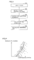
Fig. 3 is a flowchart schematically showing a procedure of an inspection method for the bearing part. -
Fig. 4 is a diagram showing one example of a relation between the stress and the number of loading at a fatigued portion of the bearing part researched preliminarily. -
Fig. 5 is a diagram showing one example of a relation between the half-value width of diffracted X-rays corresponding to a certain central angle and the number of loading that are researched preliminarily. -
Fig. 6 is a diagram showing one example of a relation between the intensity of diffracted X-rays corresponding to a certain central angle and the number of loading that are researched preliminarily. -
Fig. 7 is a diagram for describing a procedure for deriving the number of loading. - An embodiment of the present invention will be described hereinafter with reference to the drawings. In the following drawings, the same or corresponding portions are denoted by the same reference numerals, and description thereof will not be repeated.
- As shown in
Fig. 1 , aninspection apparatus 1 for a bearing part according to one embodiment of the present invention includes anirradiation unit 11 for emitting X-rays onto a bearingpart 90 to be inspected, adetector 12 for detecting annular X-rays diffracted by bearingpart 90 to be inspected, acomputation unit 13 connected todetector 12, for calculating a use condition of bearingpart 90 to be inspected, based on the annular X-rays detected bydetector 12, and adisplay unit 14 connected tocomputation unit 13, for displaying a result of computation bycomputation unit 13. -
Irradiation unit 11 includes an X-ray tube placed to be capable of facing bearingpart 90 to be inspected.Detector 12 includes a hole formed in a central portion to allow the X-rays emitted from the irradiation unit to pass through, and aplanar detection unit 12A that can face bearingpart 90 to be inspected.Computation unit 13 calculates the use condition of bearingpart 90 to be inspected, based on a database prestored in a memory unit (not shown) and the data of the annular X-rays detected bydetector 12. The calculated use condition of bearingpart 90 to be inspected is displayed ondisplay unit 14. - In addition,
inspection apparatus 1 may be portable. The "portable" inspection apparatus herein does not mean thatinspection apparatus 1 is installed in a certain place and bearingpart 90 to be inspected needs to be conveyed to that place to conduct inspection. The "portable" inspection apparatus herein means thatinspection apparatus 1 is movable and can be conveyed to a place where bearingpart 90 to be inspected is used or near that place, to conduct inspection. In order to makeinspection apparatus 1 movable, it is necessary to configureinspection apparatus 1 in a lightweight and compact manner. By using an X-ray CCD asdetection unit 12A ofdetector 12, providing the X-ray tube ofirradiation unit 11 anddetector 12 within a housing, and providingcomputation unit 13 anddisplay unit 14 as small-sized computer devices (such as personal computers),inspection apparatus 1 as a whole can be made compact. By makinginspection apparatus 1 as a whole compact, the X-ray tube ofirradiation unit 11 anddetector 12 can be brought close to bearingpart 90 to be inspected. As a result, output of the X-ray tube can be reduced, and thus, it also becomes possible to change cooling of the tube from water cooling to air cooling, andinspection apparatus 1 can be made more compact and lightweight. - An
inspection apparatus 2 can also be used in which animaging plate 12B placed on a table 12C as shown inFig. 2 is used instead ofdetection unit 12A ininspection apparatus 1 shown inFig. 1 above. Referring toFig. 2 ,inspection apparatus 2 includes afirst device 21 for emitting X-rays and receiving diffracted X-rays, and asecond device 22 for reading an image of the diffracted X-rays, calculating a use condition, and displaying a result of calculation.First device 21 has a structure basically similar to the structures ofirradiation unit 11 anddetector 12 ininspection apparatus 1 shown inFig. 1 above. However, instead ofdetector 12 ininspection apparatus 1,first device 21 includes table 12C andimaging plate 12B placed on table 12C in a freely detachable manner to face bearingpart 90 to be inspected. On the other hand,second device 22 includes a table 123 for detachably holdingimaging plate 12B, afirst motor 121 connected to table 123, for rotating table 123, and asecond motor 122 connected tofirst motor 121, for movingfirst motor 121 two-dimensionally (e.g., movingfirst motor 121 in the X-Y direction). Thesefirst motor 121 andsecond motor 122 allowimaging plate 12B held by table 123 to rotate and move two-dimensionally. Furthermore,second device 22 includes a laserbeam irradiation device 124 for emitting laser beams ontoimaging plate 12B held by table 123 and receiving the light reflected fromimaging plate 12B, and acalculation circuit 125 connected to laserbeam irradiation device 124,first motor 121 andsecond motor 122, for calculating the data of annular diffracted X-rays based on signals from these components.First motor 121,second motor 122, table 123, laserbeam irradiation device 124, andcalculation circuit 125 described above constitute aread unit 120 for reading the data of the annular diffracted X-rays fromimaging plate 12B. In addition, readunit 120,imaging plate 12B and table 12C function as an X-ray detector. -
Second device 22 further includescomputation unit 13 connected tocalculation circuit 125 inread unit 120, anddisplay unit 14 connected to the computation unit.Computation unit 13 anddisplay unit 14 have configurations similar to those ininspection apparatus 1 described above.Inspection apparatus 2 includesfirst device 21 andsecond device 22 as described above, andfirst device 21 andsecond device 22 may be portable in combination or independently. - Next, an inspection method for a bearing part using
inspection apparatus Fig. 2 , a step of preparing bearingpart 90 to be inspected and emitting X-rays onto a fatigued portion of this bearingpart 90 to be inspected (S10) is first performed. In this step (S10), referring toFigs. 1 and 2 , bearingpart 90 to be inspected is set at a prescribed position and the X-rays are emitted fromirradiation unit 11 onto bearingpart 90 to be inspected. At this time, as shown inFigs. 1 and 2 , the X-rays are emitted along an arrow α to enter bearingpart 90 to be inspected at a prescribed incidence angle. - Next, referring to
Fig. 3 , a step of detecting an X-ray diffraction ring (S20) is performed. In this step (S20), as shown inFigs. 1 and 2 , the X-rays having entered bearingpart 90 to be inspected along arrow α are diffracted to form a conical surface β, and reachdetection unit 12A orimaging plate 12B. Then, indetection unit 12A which is, for example, an X-ray CCD, annular diffracted X-rays (X-ray diffraction ring) are detected based on a signal of the intensity corresponding to the intensity of the X-rays output by each pixel. - In
inspection apparatus 2, an image of the X-ray diffraction ring is formed onimaging plate 12B. Therefore,imaging plate 12B is set inread unit 120 and the X-ray diffraction ring is detected based on the laser beam irradiation position (rotation angle and movement position) and a signal corresponding to the intensity of the reflected light inimaging plate 12B. - More specifically, although the image of the annular diffracted X-rays is formed on
imaging plate 12B, the annular diffracted X-rays cannot be detected as-is. Therefore,imaging plate 12B is detached from table 12C and is set on table 123 ofread unit 120.Imaging plate 12B held by table 123 receives the irradiation of the laser beams from laserbeam irradiation device 124, while being rotated and moved byfirst motor 121 andsecond motor 122. As a result, the signal corresponding to the intensity of the light reflected fromimaging plate 12B is output from laserbeam irradiation device 124. Namely, stimulable luminescence having an amount of light corresponding to the intensity of the X-rays is generated from a site where the image of the diffracted X-rays is formed, and thus, the intensity of the signal corresponding to the intensity of the reflected light represents the intensity of the diffracted X-rays. In addition, the rotation position and the movement position ofimaging plate 12B can be detected based on signals output from encoders infirst motor 121 andsecond motor 122. Therefore, by inputting the signal output by laserbeam irradiation device 124 and the signals output from the encoders infirst motor 121 andsecond motor 122 intocalculation circuit 125 and performing data processing, the annular diffracted X-rays can be detected similarly to the case of the X-ray CCD. - Together with
imaging plate 12B and table 12C, readunit 120 may be provided within one housing, and creation of the image of the annular diffracted X-rays onimaging plate 12B with X-ray irradiation and detection (reading) of the annular diffracted X-rays byread unit 120 may be performed continuously. - Next, referring to
Fig. 3 , a step of deriving use condition elements (S30) is performed. In this step (S30), data relevant to a condition (use condition) under which bearingpart 90 to be inspected has been used, e.g., data (use condition elements) such as normal stress at the fatigued portion of bearingpart 90 to be inspected, shear stress at the fatigued portion, a relation between a central angle and the intensity of the annular diffracted X-rays, a half-value width of a peak obtained in accordance with the central angle of the annular diffracted X-rays, and an amount of remaining austenite, is obtained based on the X-ray diffraction ring detected in the aforementioned step (S20). - Next, referring to
Fig. 3 , a step of calculating a use condition (S40) is performed. In this step (S40), the use condition of bearingpart 90 to be inspected is calculated based on the use condition elements obtained in the aforementioned step (S30). Specifically, the use condition can be estimated as described below, for example. Estimation (calculation) of the use condition is performed incomputation unit 13 connected to detector 12 (seeFigs. 1 and 2 ). - The inventors of the present invention researched X-ray diffraction rings for the rolling bearing used under different use conditions. As a result of their research, the inventors of the present invention found that the compressive stress which is the normal stress, the intensity distribution with respect to the central angle of the X-ray diffraction ring, and the distribution of the half-value width change depending on the use condition of the rolling bearing. Therefore, by preliminarily researching a relation between each of the aforementioned use condition elements and the actual use condition (the number of loading, the load and the oil film parameter) based on the X-ray diffraction ring including a large amount of data, it is possible to estimate, based on this relation, the actual use condition when a prescribed use condition element is derived for bearing
part 90 to be inspected. - It is now assumed that relations (databases) shown in
Figs. 4 to 6 are obtained as a result of research of diffraction X-ray rings at fatigued portions of bearing parts that form various types of rolling bearings used under various use conditions. InFigs. 4 to 6 , the vertical axes indicate the number of actual loading, and the horizontal axes indicate the stress (compressive stress), the half-value width corresponding to a certain central angle, and the peak intensity corresponding to a certain central angle, respectively, which are obtained as a result of analysis of the bearing part at the number of loading by using the aforementioned X-ray diffraction ring. A curved line in each figure indicates a relation between the number of loading and each use condition element calculated based on data points in the figure. - Namely, when the X-rays are emitted onto the bearing part (bearing
part 90 to be inspected) forming the rolling bearing after use in the aforementioned step (S20) and the bearing part is analyzed by using the entire X-ray diffraction ring detected in the step (S40), analytical values corresponding to the horizontal axes inFigs. 4 to 6 are obtained, and thus, the highest possible number of loading can be derived from these analytical values by using the relations shown inFigs. 4 to 6 . More specifically, referring toFig. 7 , assuming that the compressive stress of bearingpart 90 to be inspected which was obtained from the X-ray diffraction ring is, for example, x, the number of loading can be estimated as y. Similarly, by preliminarily researching a relation between the compressive stress or the other use condition elements and the other use condition (the load, the oil film parameter), the other use condition of bearingpart 90 to be inspected can be derived (estimated) by using this relation. - Assuming now that the compressive stress of bearing
part 90 to be inspected is x, the probability that the number of loading is y is the highest, judging from only this data. However, the number of loading calculated as described above includes variations in analysis result and variations caused by the other use condition (the load, the oil film parameter). - As shown in
Fig. 7 , the number of loading has a distribution like F(y) with respect to the compressive stress. Similarly, the number of loading has distributions with respect to all use condition elements (such as the half-value width corresponding to a certain central angle, and the peak intensity corresponding to a certain central angle). Therefore, by multiplying all of these distribution functions and determining at which number of loading the multiplied functions are maximized, the most likely number of loading can be derived. Therefore, when the number of loading is derived, it is preferable to multiply, as many as possible, the distribution functions for the number of loading derived based on relations between the number of loading and the respective use condition elements that are preliminarily researched, and to derive the most likely number of loading. More specifically, it is preferable to multiply all distribution functions for the number of loading derived based on, for example, a relation of the number of loading with each of the normal stress at the fatigued portion, the shear stress at the fatigued portion, the amount of remaining austenite, the relation between the central angle and the intensity of the annular diffracted X-rays, and the half-value width of the peak obtained in accordance with the central angle of the annular diffracted X-rays, about the preliminarily researched bearing part, and to statistically derive the most likely number of loading. Then, the most likely values of not only the number of loading but also the load and the oil film parameter are similarly derived statistically. As a result, the use condition can be estimated with high precision. The calculated use condition is displayed ondisplay unit 14 connected tocomputation unit 13. - Next, referring to
Fig. 3 , a step of calculating the remaining life of the rolling bearing (S50) is performed. In this step (S50), the remaining life of bearingpart 90 to be inspected is calculated based on the use condition derived in the aforementioned step (S40). Specifically, the remaining life can be estimated, for example, as described below. - Generally, the life of the rolling bearing is expressed by the following equation (1):


- Ln: n% life (the number of loading), a1: reliability coefficient, a2: use condition coefficient (coefficient determined by use condition such as lubrication condition), P: load (kgf), C: dynamic load rating (kgf), p: load life exponent (ball bearing: p=3, roller bearing: p=10/3), e: Weibull slope (ball bearing: e=10/9, roller bearing: e=9/8) (e=1.5 in the case of 10% life or less).
- Therefore, by applying the use condition (the number of loading, the load and the oil film parameter) derived in the aforementioned step (S40) to the aforementioned equation (1), the remaining life of bearing
part 90 to be inspected is calculated. The calculated remaining life is displayed ondisplay unit 14. With the aforementioned process, the inspection method for the bearing part usinginspection apparatus 1 according to the present embodiment is completed. - In the aforementioned inspection method for the bearing part using
inspection apparatus - In the aforementioned embodiment, the maximum likelihood estimation method has been described as one example of the statistical method for estimating the use condition. However, instead of this method, other statistical methods, e.g., a Bayesian method may be used.
- It should be understood that the embodiment disclosed herein is illustrative and not limitative in any respect. The scope of the present invention is defined by the terms of the claims, rather than the description above, and is intended to include any modifications within the scope and meaning equivalent to the terms of the claims.
- The inspection method for the bearing part and the inspection apparatus for the bearing part according to the present invention are particularly advantageously applicable to an inspection method for a bearing part and an inspection apparatus for a bearing part in which high precision is required.
- 1, 2 inspection apparatus; 11 irradiation unit; 12 detector; 12A detection unit; 12B imaging plate; 12C table; 13 computation unit; 14 display unit; 21 first device; 22 second device; 90 bearing part to be inspected; 120 read unit; 121 first motor; 122 second motor; 123 table; 124 laser beam irradiation device; 125 calculation circuit.
Claims (8)
- An inspection method for a bearing part, comprising the steps of:emitting X-rays onto a fatigued portion of a bearing part to be inspected;detecting annular diffracted X-rays diffracted by said fatigued portion; andestimating a use condition of said bearing part to be inspected, based on said detected annular diffracted X-rays.
- The inspection method for a bearing part according to claim 1, wherein said step of estimating a use condition of said bearing part to be inspected includes the steps of:deriving use condition elements including normal stress at said fatigued portion, shear stress at said fatigued portion, a relation between a central angle and an intensity of said annular diffracted X-rays, and a half-value width of a peak obtained in accordance with the central angle of said annular diffracted X-rays, based on said annular diffracted X-rays detected in said step of detecting annular diffracted X-rays; andcalculating the use condition of said bearing part to be inspected, based on at least one of said derived use condition elements.
- The inspection method for a bearing part according to claim 1, further comprising the step of
evaluating a remaining life of said bearing part to be inspected, based on the use condition of said bearing part to be inspected which was calculated in said step of estimating a use condition of said bearing part to be inspected. - The inspection method for a bearing part according to claim 2, wherein said use condition elements further include an amount of austenite remaining in said fatigued portion.
- The inspection method for a bearing part according to claim 4, wherein
in said step of estimating a use condition, the number of loading of stress applied to said fatigued portion of said bearing part to be inspected, a load applied to said fatigued portion, and an oil film parameter at said fatigued portion are calculated based on a relation of at least any one of the normal stress at the fatigued portion, the shear stress at the fatigued portion, the amount of remaining austenite, the relation between the central angle and the intensity of the annular diffracted X-rays, and the half-value width of the peak obtained in accordance with the central angle of the annular diffracted X-rays, about the preliminarily researched bearing part, with the number of loading of stress applied to the fatigued portion of the bearing part, the load applied to the fatigued portion of the bearing part, and the oil film parameter at the fatigued portion of the bearing part. - The inspection method for a bearing part according to claim 5, wherein
in said step of estimating a use condition, each of the number of loading of stress applied to said fatigued portion of said bearing part to be inspected, the load applied to said fatigued portion of said bearing part to be inspected, and the oil film parameter at said fatigued portion of said bearing part to be inspected is statistically calculated to take into consideration a relation of each of the normal stress at the fatigued portion, the shear stress at the fatigued portion, the amount of remaining austenite, the relation between the central angle and the intensity of the annular diffracted X-rays, and the half-value width of the peak obtained in accordance with the central angle of the annular diffracted X-rays, about the preliminarily researched bearing part, with all of the number of loading of stress applied to the fatigued portion of the bearing part, the load applied to the fatigued portion of the bearing part, and the oil film parameter at the fatigued portion of the bearing part. - An inspection apparatus for a bearing part, comprising:an irradiation unit for emitting X-rays onto a bearing part to be inspected;a detector for detecting annular X-rays diffracted by said bearing part to be inspected; anda computation unit connected to said detector, for calculating a use condition of said bearing part to be inspected, based on said annular X-rays detected by said detector.
- The inspection apparatus for a bearing part according to claim 7, wherein the inspection apparatus for a bearing part is portable.
Applications Claiming Priority (2)
| Application Number | Priority Date | Filing Date | Title |
|---|---|---|---|
| JP2012150642A JP5958999B2 (en) | 2012-07-04 | 2012-07-04 | Bearing part inspection method and bearing part inspection apparatus |
| PCT/JP2013/068131 WO2014007246A1 (en) | 2012-07-04 | 2013-07-02 | Bearing part inspection method and bearing part inspection device |
Publications (3)
| Publication Number | Publication Date |
|---|---|
| EP2871467A1 true EP2871467A1 (en) | 2015-05-13 |
| EP2871467A4 EP2871467A4 (en) | 2016-03-02 |
| EP2871467B1 EP2871467B1 (en) | 2018-10-24 |
Family
ID=49882001
Family Applications (1)
| Application Number | Title | Priority Date | Filing Date |
|---|---|---|---|
| EP13813631.2A Not-in-force EP2871467B1 (en) | 2012-07-04 | 2013-07-02 | Bearing part inspection method and bearing part inspection device |
Country Status (5)
| Country | Link |
|---|---|
| US (1) | US9702834B2 (en) |
| EP (1) | EP2871467B1 (en) |
| JP (1) | JP5958999B2 (en) |
| CN (1) | CN104641225B (en) |
| WO (1) | WO2014007246A1 (en) |
Families Citing this family (20)
| Publication number | Priority date | Publication date | Assignee | Title |
|---|---|---|---|---|
| JP6394513B2 (en) * | 2015-06-18 | 2018-09-26 | 新東工業株式会社 | Residual stress measuring device and residual stress measuring method |
| JP6593260B2 (en) * | 2016-06-30 | 2019-10-23 | 株式会社豊田自動織機 | Bearing management method and management device for loom opening device |
| JP6762818B2 (en) * | 2016-09-09 | 2020-09-30 | Ntn株式会社 | Bearing part life diagnosis method, bearing part life diagnosis device, and bearing part life diagnosis program |
| JP6695243B2 (en) * | 2016-09-09 | 2020-05-20 | Ntn株式会社 | Bearing component life diagnosis method, bearing component life diagnosis device, and bearing component life diagnosis program |
| WO2018047774A1 (en) * | 2016-09-09 | 2018-03-15 | Ntn株式会社 | Method for diagnosing service life of bearing component, device for diagnosing service life of bearing component, and program for diagnosing service life of bearing component |
| JP6762817B2 (en) * | 2016-09-09 | 2020-09-30 | Ntn株式会社 | Bearing part life diagnosis method, bearing part life diagnosis device, and bearing part life diagnosis program |
| US10539518B2 (en) * | 2017-05-15 | 2020-01-21 | Weatherford Technology Holdings, Llc | X-ray based fatigue inspection of downhole component |
| JP6775777B2 (en) * | 2017-08-29 | 2020-10-28 | 株式会社リガク | How to display the measurement result in X-ray diffraction measurement |
| JP7064383B2 (en) * | 2018-05-29 | 2022-05-10 | Ntn株式会社 | Performance evaluation method for rolling parts |
| JP7372155B2 (en) * | 2019-02-22 | 2023-10-31 | Ntn株式会社 | Method for estimating fatigue level of rolling parts, device for estimating fatigue level of rolling parts, program for estimating fatigue level of rolling parts |
| JP6770210B1 (en) * | 2020-04-01 | 2020-10-14 | 株式会社日産アーク | Dynamic state observation system |
| JP2021162568A (en) * | 2020-04-01 | 2021-10-11 | 株式会社日産アーク | Dynamic state observation system |
| JP7587967B2 (en) * | 2020-11-20 | 2024-11-21 | 株式会社不二越 | X-ray diffraction measurement equipment |
| JP7621105B2 (en) * | 2020-12-14 | 2025-01-24 | Ntn株式会社 | Calculation method of oil film parameters |
| JP7610467B2 (en) * | 2021-05-21 | 2025-01-08 | 株式会社神戸製鋼所 | Metal fatigue evaluation device, method and program |
| JP7600041B2 (en) * | 2021-06-25 | 2024-12-16 | 株式会社神戸製鋼所 | Metal fatigue evaluation method |
| CN113642414A (en) * | 2021-07-19 | 2021-11-12 | 北京航空航天大学 | A Transformer Model-Based Method for Predicting the Remaining Service Life of Rolling Bearings |
| CN114046729B (en) * | 2021-10-27 | 2023-07-04 | 新兴铸管股份有限公司 | Bearing quick disassembly detection method |
| JP7701894B2 (en) * | 2022-04-06 | 2025-07-02 | 株式会社神戸製鋼所 | METAL FATIGUE EVALUATION METHOD, PROGRAM AND APPARATUS THEREOF |
| CN115656206A (en) * | 2022-10-31 | 2023-01-31 | 南锐智能传动(江苏)有限公司 | Online monitoring system for abrasion conditions of bearing and gear |
Family Cites Families (12)
| Publication number | Priority date | Publication date | Assignee | Title |
|---|---|---|---|---|
| JPS5687849A (en) * | 1979-12-19 | 1981-07-16 | Hitachi Ltd | Foreknowing method for remaining life by x-rays |
| JPS5744841A (en) * | 1980-09-01 | 1982-03-13 | Hitachi Ltd | Method and apparatus for x-ray diffraction |
| JPH0621783B2 (en) * | 1986-04-21 | 1994-03-23 | 三菱重工業株式会社 | Fatigue / remaining life evaluation method for machine parts |
| JP4276106B2 (en) * | 2004-02-24 | 2009-06-10 | 財団法人鉄道総合技術研究所 | X-ray diffraction apparatus and X-ray diffraction system |
| US7918141B1 (en) * | 2007-04-03 | 2011-04-05 | The United States Of America As Represented By The Secretary Of The Air Force | Local residual stress measurement and analysis for detection and prediction of damage in thermal barrier coatings |
| JP5076719B2 (en) * | 2007-08-07 | 2012-11-21 | 日本精工株式会社 | Predicting remaining life of rolling bearings |
| US7623973B1 (en) * | 2008-05-05 | 2009-11-24 | Gm Global Technology Operations, Inc. | Methods and systems to predict fatigue life in aluminum castings |
| US8477905B2 (en) * | 2009-03-20 | 2013-07-02 | Proto Manufacturing Ltd. | Non-destructive testing systems and methods |
| JP5339253B2 (en) * | 2009-07-24 | 2013-11-13 | 国立大学法人金沢大学 | X-ray stress measurement method |
| JP2011069684A (en) * | 2009-09-25 | 2011-04-07 | Ntn Corp | Method of estimating use condition on rolling bearing |
| CN102216862A (en) * | 2009-12-17 | 2011-10-12 | 日本精工株式会社 | Bearing remaining life prediction method, remaining life diagnosis device and bearing diagnosis system |
| CN102721712B (en) * | 2012-04-27 | 2014-07-02 | 中国航空工业集团公司北京航空材料研究院 | Method and device for measuring metal pipe texture |
-
2012
- 2012-07-04 JP JP2012150642A patent/JP5958999B2/en active Active
-
2013
- 2013-07-02 EP EP13813631.2A patent/EP2871467B1/en not_active Not-in-force
- 2013-07-02 CN CN201380035589.2A patent/CN104641225B/en not_active Expired - Fee Related
- 2013-07-02 US US14/412,629 patent/US9702834B2/en not_active Expired - Fee Related
- 2013-07-02 WO PCT/JP2013/068131 patent/WO2014007246A1/en not_active Ceased
Also Published As
| Publication number | Publication date |
|---|---|
| CN104641225B (en) | 2018-06-01 |
| US9702834B2 (en) | 2017-07-11 |
| WO2014007246A1 (en) | 2014-01-09 |
| US20150146857A1 (en) | 2015-05-28 |
| JP2014013188A (en) | 2014-01-23 |
| CN104641225A (en) | 2015-05-20 |
| EP2871467B1 (en) | 2018-10-24 |
| EP2871467A4 (en) | 2016-03-02 |
| JP5958999B2 (en) | 2016-08-02 |
Similar Documents
| Publication | Publication Date | Title |
|---|---|---|
| EP2871467B1 (en) | Bearing part inspection method and bearing part inspection device | |
| JP6556266B2 (en) | Defect inspection apparatus, method and program | |
| Jones et al. | Asteroid discovery and characterization with the large synoptic survey telescope | |
| EP2873961A1 (en) | Device for estimating service life and method for estimating service life of rolling bearing | |
| Poozesh et al. | Full field inspection of a utility scale wind turbine blade using digital image correlation | |
| US20130089182A1 (en) | Evaluation System and Evaluation Method of Plastic Strain | |
| Baizeau et al. | Cutting force sensor based on digital image correlation for segmented chip formation analysis | |
| Jerjen et al. | Detection of stress whitening in plastics with the help of X-ray dark field imaging | |
| Kanis et al. | Innovative diagnostics of the railway track superstructure | |
| Koshti | Using requirements on merit ratios for assessing reliability of NDE flaw detection in multi-hit detection in digital radiography | |
| Beyer et al. | Uncertainty assessment of contaminant plume length estimates in heterogeneous aquifers | |
| US9880115B2 (en) | Method for characterizing a material | |
| Koshti | X-ray ray tracing simulation and flaw parameters for crack detection | |
| Farhidzadeh et al. | A vision-based technique for damage assessment of reinforced concrete structures | |
| Morais et al. | The population of Near Earth Asteroids in coorbital motion with Venus | |
| EP3715782B1 (en) | Method for slot inspection | |
| Koshti | Simulating the x-ray image contrast to setup techniques with desired flaw detectability | |
| Panas et al. | A systems approach to estimating the uncertainty limits of X-ray radiographic metrology | |
| Buratti et al. | An analytical method for optimizing imaging parameters in industrial x-ray computed tomography for dimensional measurements on multimaterial workpieces | |
| US20170322144A1 (en) | Electrochemical testing for corrosion analysis | |
| Koshti | Assessing reliability of NDE flaw detection using smaller number of demonstration data points | |
| Matern et al. | How much does image quality influence the form error in industrial X-Ray CT | |
| JP7499931B2 (en) | Method for estimating contact stress of rolling parts, program for estimating contact stress of rolling parts, and device for estimating contact stress of rolling parts | |
| JP5664186B2 (en) | Method and apparatus for analyzing contact area between solids | |
| Adams | Quantitative radiographic investigation of mechanical fasteners in wood connections |
Legal Events
| Date | Code | Title | Description |
|---|---|---|---|
| PUAI | Public reference made under article 153(3) epc to a published international application that has entered the european phase |
Free format text: ORIGINAL CODE: 0009012 |
|
| 17P | Request for examination filed |
Effective date: 20150120 |
|
| AK | Designated contracting states |
Kind code of ref document: A1 Designated state(s): AL AT BE BG CH CY CZ DE DK EE ES FI FR GB GR HR HU IE IS IT LI LT LU LV MC MK MT NL NO PL PT RO RS SE SI SK SM TR |
|
| AX | Request for extension of the european patent |
Extension state: BA ME |
|
| RIN1 | Information on inventor provided before grant (corrected) |
Inventor name: YAGITA, KAZUHIRO Inventor name: MARUYAMA, YOUICHI Inventor name: SASAKI, THOSHIHIKO Inventor name: FUJITA, TAKUMI |
|
| DAX | Request for extension of the european patent (deleted) | ||
| RIN1 | Information on inventor provided before grant (corrected) |
Inventor name: YAGITA, KAZUHIRO Inventor name: SASAKI, THOSHIHIKO Inventor name: FUJITA, TAKUMI Inventor name: MARUYAMA, YOUICHI |
|
| REG | Reference to a national code |
Ref country code: DE Ref legal event code: R079 Ref document number: 602013045666 Country of ref document: DE Free format text: PREVIOUS MAIN CLASS: G01N0023200000 Ipc: G01N0023207000 |
|
| RA4 | Supplementary search report drawn up and despatched (corrected) |
Effective date: 20160129 |
|
| RIC1 | Information provided on ipc code assigned before grant |
Ipc: G01N 23/207 20060101AFI20160125BHEP Ipc: G01N 23/20 20060101ALI20160125BHEP |
|
| STAA | Information on the status of an ep patent application or granted ep patent |
Free format text: STATUS: EXAMINATION IS IN PROGRESS |
|
| 17Q | First examination report despatched |
Effective date: 20170712 |
|
| GRAP | Despatch of communication of intention to grant a patent |
Free format text: ORIGINAL CODE: EPIDOSNIGR1 |
|
| STAA | Information on the status of an ep patent application or granted ep patent |
Free format text: STATUS: GRANT OF PATENT IS INTENDED |
|
| INTG | Intention to grant announced |
Effective date: 20180404 |
|
| GRAS | Grant fee paid |
Free format text: ORIGINAL CODE: EPIDOSNIGR3 |
|
| RIN1 | Information on inventor provided before grant (corrected) |
Inventor name: SASAKI, THOSHIHIKO Inventor name: YAGITA, KAZUHIRO Inventor name: MARUYAMA, YOUICHI Inventor name: FUJITA, TAKUMI |
|
| RIN1 | Information on inventor provided before grant (corrected) |
Inventor name: SASAKI, TOSHIHIKO Inventor name: FUJITA, TAKUMI Inventor name: MARUYAMA, YOUICHI Inventor name: YAGITA, KAZUHIRO |
|
| GRAA | (expected) grant |
Free format text: ORIGINAL CODE: 0009210 |
|
| STAA | Information on the status of an ep patent application or granted ep patent |
Free format text: STATUS: THE PATENT HAS BEEN GRANTED |
|
| AK | Designated contracting states |
Kind code of ref document: B1 Designated state(s): AL AT BE BG CH CY CZ DE DK EE ES FI FR GB GR HR HU IE IS IT LI LT LU LV MC MK MT NL NO PL PT RO RS SE SI SK SM TR |
|
| REG | Reference to a national code |
Ref country code: CH Ref legal event code: EP |
|
| REG | Reference to a national code |
Ref country code: IE Ref legal event code: FG4D |
|
| REG | Reference to a national code |
Ref country code: AT Ref legal event code: REF Ref document number: 1057285 Country of ref document: AT Kind code of ref document: T Effective date: 20181115 |
|
| REG | Reference to a national code |
Ref country code: DE Ref legal event code: R096 Ref document number: 602013045666 Country of ref document: DE |
|
| REG | Reference to a national code |
Ref country code: NL Ref legal event code: MP Effective date: 20181024 |
|
| REG | Reference to a national code |
Ref country code: LT Ref legal event code: MG4D |
|
| REG | Reference to a national code |
Ref country code: AT Ref legal event code: MK05 Ref document number: 1057285 Country of ref document: AT Kind code of ref document: T Effective date: 20181024 |
|
| PG25 | Lapsed in a contracting state [announced via postgrant information from national office to epo] |
Ref country code: NL Free format text: LAPSE BECAUSE OF FAILURE TO SUBMIT A TRANSLATION OF THE DESCRIPTION OR TO PAY THE FEE WITHIN THE PRESCRIBED TIME-LIMIT Effective date: 20181024 |
|
| PG25 | Lapsed in a contracting state [announced via postgrant information from national office to epo] |
Ref country code: ES Free format text: LAPSE BECAUSE OF FAILURE TO SUBMIT A TRANSLATION OF THE DESCRIPTION OR TO PAY THE FEE WITHIN THE PRESCRIBED TIME-LIMIT Effective date: 20181024 Ref country code: LV Free format text: LAPSE BECAUSE OF FAILURE TO SUBMIT A TRANSLATION OF THE DESCRIPTION OR TO PAY THE FEE WITHIN THE PRESCRIBED TIME-LIMIT Effective date: 20181024 Ref country code: PL Free format text: LAPSE BECAUSE OF FAILURE TO SUBMIT A TRANSLATION OF THE DESCRIPTION OR TO PAY THE FEE WITHIN THE PRESCRIBED TIME-LIMIT Effective date: 20181024 Ref country code: HR Free format text: LAPSE BECAUSE OF FAILURE TO SUBMIT A TRANSLATION OF THE DESCRIPTION OR TO PAY THE FEE WITHIN THE PRESCRIBED TIME-LIMIT Effective date: 20181024 Ref country code: BG Free format text: LAPSE BECAUSE OF FAILURE TO SUBMIT A TRANSLATION OF THE DESCRIPTION OR TO PAY THE FEE WITHIN THE PRESCRIBED TIME-LIMIT Effective date: 20190124 Ref country code: IS Free format text: LAPSE BECAUSE OF FAILURE TO SUBMIT A TRANSLATION OF THE DESCRIPTION OR TO PAY THE FEE WITHIN THE PRESCRIBED TIME-LIMIT Effective date: 20190224 Ref country code: FI Free format text: LAPSE BECAUSE OF FAILURE TO SUBMIT A TRANSLATION OF THE DESCRIPTION OR TO PAY THE FEE WITHIN THE PRESCRIBED TIME-LIMIT Effective date: 20181024 Ref country code: LT Free format text: LAPSE BECAUSE OF FAILURE TO SUBMIT A TRANSLATION OF THE DESCRIPTION OR TO PAY THE FEE WITHIN THE PRESCRIBED TIME-LIMIT Effective date: 20181024 Ref country code: AT Free format text: LAPSE BECAUSE OF FAILURE TO SUBMIT A TRANSLATION OF THE DESCRIPTION OR TO PAY THE FEE WITHIN THE PRESCRIBED TIME-LIMIT Effective date: 20181024 Ref country code: NO Free format text: LAPSE BECAUSE OF FAILURE TO SUBMIT A TRANSLATION OF THE DESCRIPTION OR TO PAY THE FEE WITHIN THE PRESCRIBED TIME-LIMIT Effective date: 20190124 |
|
| PG25 | Lapsed in a contracting state [announced via postgrant information from national office to epo] |
Ref country code: SE Free format text: LAPSE BECAUSE OF FAILURE TO SUBMIT A TRANSLATION OF THE DESCRIPTION OR TO PAY THE FEE WITHIN THE PRESCRIBED TIME-LIMIT Effective date: 20181024 Ref country code: RS Free format text: LAPSE BECAUSE OF FAILURE TO SUBMIT A TRANSLATION OF THE DESCRIPTION OR TO PAY THE FEE WITHIN THE PRESCRIBED TIME-LIMIT Effective date: 20181024 Ref country code: PT Free format text: LAPSE BECAUSE OF FAILURE TO SUBMIT A TRANSLATION OF THE DESCRIPTION OR TO PAY THE FEE WITHIN THE PRESCRIBED TIME-LIMIT Effective date: 20190224 Ref country code: GR Free format text: LAPSE BECAUSE OF FAILURE TO SUBMIT A TRANSLATION OF THE DESCRIPTION OR TO PAY THE FEE WITHIN THE PRESCRIBED TIME-LIMIT Effective date: 20190125 Ref country code: AL Free format text: LAPSE BECAUSE OF FAILURE TO SUBMIT A TRANSLATION OF THE DESCRIPTION OR TO PAY THE FEE WITHIN THE PRESCRIBED TIME-LIMIT Effective date: 20181024 |
|
| REG | Reference to a national code |
Ref country code: DE Ref legal event code: R097 Ref document number: 602013045666 Country of ref document: DE |
|
| PG25 | Lapsed in a contracting state [announced via postgrant information from national office to epo] |
Ref country code: DK Free format text: LAPSE BECAUSE OF FAILURE TO SUBMIT A TRANSLATION OF THE DESCRIPTION OR TO PAY THE FEE WITHIN THE PRESCRIBED TIME-LIMIT Effective date: 20181024 Ref country code: CZ Free format text: LAPSE BECAUSE OF FAILURE TO SUBMIT A TRANSLATION OF THE DESCRIPTION OR TO PAY THE FEE WITHIN THE PRESCRIBED TIME-LIMIT Effective date: 20181024 Ref country code: IT Free format text: LAPSE BECAUSE OF FAILURE TO SUBMIT A TRANSLATION OF THE DESCRIPTION OR TO PAY THE FEE WITHIN THE PRESCRIBED TIME-LIMIT Effective date: 20181024 |
|
| PG25 | Lapsed in a contracting state [announced via postgrant information from national office to epo] |
Ref country code: SK Free format text: LAPSE BECAUSE OF FAILURE TO SUBMIT A TRANSLATION OF THE DESCRIPTION OR TO PAY THE FEE WITHIN THE PRESCRIBED TIME-LIMIT Effective date: 20181024 Ref country code: RO Free format text: LAPSE BECAUSE OF FAILURE TO SUBMIT A TRANSLATION OF THE DESCRIPTION OR TO PAY THE FEE WITHIN THE PRESCRIBED TIME-LIMIT Effective date: 20181024 Ref country code: EE Free format text: LAPSE BECAUSE OF FAILURE TO SUBMIT A TRANSLATION OF THE DESCRIPTION OR TO PAY THE FEE WITHIN THE PRESCRIBED TIME-LIMIT Effective date: 20181024 Ref country code: SM Free format text: LAPSE BECAUSE OF FAILURE TO SUBMIT A TRANSLATION OF THE DESCRIPTION OR TO PAY THE FEE WITHIN THE PRESCRIBED TIME-LIMIT Effective date: 20181024 |
|
| PLBE | No opposition filed within time limit |
Free format text: ORIGINAL CODE: 0009261 |
|
| STAA | Information on the status of an ep patent application or granted ep patent |
Free format text: STATUS: NO OPPOSITION FILED WITHIN TIME LIMIT |
|
| 26N | No opposition filed |
Effective date: 20190725 |
|
| PG25 | Lapsed in a contracting state [announced via postgrant information from national office to epo] |
Ref country code: SI Free format text: LAPSE BECAUSE OF FAILURE TO SUBMIT A TRANSLATION OF THE DESCRIPTION OR TO PAY THE FEE WITHIN THE PRESCRIBED TIME-LIMIT Effective date: 20181024 |
|
| PG25 | Lapsed in a contracting state [announced via postgrant information from national office to epo] |
Ref country code: MC Free format text: LAPSE BECAUSE OF FAILURE TO SUBMIT A TRANSLATION OF THE DESCRIPTION OR TO PAY THE FEE WITHIN THE PRESCRIBED TIME-LIMIT Effective date: 20181024 |
|
| REG | Reference to a national code |
Ref country code: CH Ref legal event code: PL |
|
| GBPC | Gb: european patent ceased through non-payment of renewal fee |
Effective date: 20190702 |
|
| PG25 | Lapsed in a contracting state [announced via postgrant information from national office to epo] |
Ref country code: TR Free format text: LAPSE BECAUSE OF FAILURE TO SUBMIT A TRANSLATION OF THE DESCRIPTION OR TO PAY THE FEE WITHIN THE PRESCRIBED TIME-LIMIT Effective date: 20181024 |
|
| REG | Reference to a national code |
Ref country code: BE Ref legal event code: MM Effective date: 20190731 |
|
| PG25 | Lapsed in a contracting state [announced via postgrant information from national office to epo] |
Ref country code: GB Free format text: LAPSE BECAUSE OF NON-PAYMENT OF DUE FEES Effective date: 20190702 |
|
| PG25 | Lapsed in a contracting state [announced via postgrant information from national office to epo] |
Ref country code: BE Free format text: LAPSE BECAUSE OF NON-PAYMENT OF DUE FEES Effective date: 20190731 Ref country code: LU Free format text: LAPSE BECAUSE OF NON-PAYMENT OF DUE FEES Effective date: 20190702 Ref country code: CH Free format text: LAPSE BECAUSE OF NON-PAYMENT OF DUE FEES Effective date: 20190731 Ref country code: LI Free format text: LAPSE BECAUSE OF NON-PAYMENT OF DUE FEES Effective date: 20190731 |
|
| PG25 | Lapsed in a contracting state [announced via postgrant information from national office to epo] |
Ref country code: IE Free format text: LAPSE BECAUSE OF NON-PAYMENT OF DUE FEES Effective date: 20190702 |
|
| PGFP | Annual fee paid to national office [announced via postgrant information from national office to epo] |
Ref country code: FR Payment date: 20200612 Year of fee payment: 8 |
|
| PGFP | Annual fee paid to national office [announced via postgrant information from national office to epo] |
Ref country code: DE Payment date: 20200617 Year of fee payment: 8 |
|
| PG25 | Lapsed in a contracting state [announced via postgrant information from national office to epo] |
Ref country code: CY Free format text: LAPSE BECAUSE OF FAILURE TO SUBMIT A TRANSLATION OF THE DESCRIPTION OR TO PAY THE FEE WITHIN THE PRESCRIBED TIME-LIMIT Effective date: 20181024 |
|
| PG25 | Lapsed in a contracting state [announced via postgrant information from national office to epo] |
Ref country code: HU Free format text: LAPSE BECAUSE OF FAILURE TO SUBMIT A TRANSLATION OF THE DESCRIPTION OR TO PAY THE FEE WITHIN THE PRESCRIBED TIME-LIMIT; INVALID AB INITIO Effective date: 20130702 Ref country code: MT Free format text: LAPSE BECAUSE OF FAILURE TO SUBMIT A TRANSLATION OF THE DESCRIPTION OR TO PAY THE FEE WITHIN THE PRESCRIBED TIME-LIMIT Effective date: 20181024 |
|
| REG | Reference to a national code |
Ref country code: DE Ref legal event code: R119 Ref document number: 602013045666 Country of ref document: DE |
|
| PG25 | Lapsed in a contracting state [announced via postgrant information from national office to epo] |
Ref country code: DE Free format text: LAPSE BECAUSE OF NON-PAYMENT OF DUE FEES Effective date: 20220201 |
|
| PG25 | Lapsed in a contracting state [announced via postgrant information from national office to epo] |
Ref country code: FR Free format text: LAPSE BECAUSE OF NON-PAYMENT OF DUE FEES Effective date: 20210731 |
|
| PG25 | Lapsed in a contracting state [announced via postgrant information from national office to epo] |
Ref country code: MK Free format text: LAPSE BECAUSE OF FAILURE TO SUBMIT A TRANSLATION OF THE DESCRIPTION OR TO PAY THE FEE WITHIN THE PRESCRIBED TIME-LIMIT Effective date: 20181024 |