EP2871453A1 - Gauge for measuring two-dimensional heat flux - Google Patents
Gauge for measuring two-dimensional heat flux Download PDFInfo
- Publication number
- EP2871453A1 EP2871453A1 EP20130813581 EP13813581A EP2871453A1 EP 2871453 A1 EP2871453 A1 EP 2871453A1 EP 20130813581 EP20130813581 EP 20130813581 EP 13813581 A EP13813581 A EP 13813581A EP 2871453 A1 EP2871453 A1 EP 2871453A1
- Authority
- EP
- European Patent Office
- Prior art keywords
- measuring
- temperature measuring
- heat flux
- temperature
- gauge
- Prior art date
- Legal status (The legal status is an assumption and is not a legal conclusion. Google has not performed a legal analysis and makes no representation as to the accuracy of the status listed.)
- Granted
Links
- 230000004907 flux Effects 0.000 title claims abstract description 87
- 238000010438 heat treatment Methods 0.000 claims abstract description 4
- 238000003780 insertion Methods 0.000 claims description 111
- 230000037431 insertion Effects 0.000 claims description 111
- 238000001816 cooling Methods 0.000 description 27
- 238000000034 method Methods 0.000 description 25
- 230000008569 process Effects 0.000 description 14
- 238000012546 transfer Methods 0.000 description 6
- 230000008859 change Effects 0.000 description 4
- 238000005259 measurement Methods 0.000 description 4
- 238000005096 rolling process Methods 0.000 description 4
- 229910000831 Steel Inorganic materials 0.000 description 3
- 239000012530 fluid Substances 0.000 description 3
- 238000004519 manufacturing process Methods 0.000 description 3
- 239000000463 material Substances 0.000 description 3
- 239000010959 steel Substances 0.000 description 3
- XLYOFNOQVPJJNP-UHFFFAOYSA-N water Substances O XLYOFNOQVPJJNP-UHFFFAOYSA-N 0.000 description 3
- 230000000994 depressogenic effect Effects 0.000 description 2
- 239000010935 stainless steel Substances 0.000 description 2
- 229910001220 stainless steel Inorganic materials 0.000 description 2
- 229910000975 Carbon steel Inorganic materials 0.000 description 1
- 230000002159 abnormal effect Effects 0.000 description 1
- 238000009529 body temperature measurement Methods 0.000 description 1
- 238000009835 boiling Methods 0.000 description 1
- 239000010962 carbon steel Substances 0.000 description 1
- 230000003247 decreasing effect Effects 0.000 description 1
- 238000009826 distribution Methods 0.000 description 1
- 230000020169 heat generation Effects 0.000 description 1
- 239000002184 metal Substances 0.000 description 1
- 239000007769 metal material Substances 0.000 description 1
- 238000012986 modification Methods 0.000 description 1
- 230000004048 modification Effects 0.000 description 1
- 230000000704 physical effect Effects 0.000 description 1
- 230000005855 radiation Effects 0.000 description 1
- 239000007787 solid Substances 0.000 description 1
- 238000012360 testing method Methods 0.000 description 1
- 230000009466 transformation Effects 0.000 description 1
- 238000003466 welding Methods 0.000 description 1
Images




Classifications
-
- G—PHYSICS
- G01—MEASURING; TESTING
- G01K—MEASURING TEMPERATURE; MEASURING QUANTITY OF HEAT; THERMALLY-SENSITIVE ELEMENTS NOT OTHERWISE PROVIDED FOR
- G01K17/00—Measuring quantity of heat
- G01K17/06—Measuring quantity of heat conveyed by flowing media, e.g. in heating systems e.g. the quantity of heat in a transporting medium, delivered to or consumed in an expenditure device
- G01K17/08—Measuring quantity of heat conveyed by flowing media, e.g. in heating systems e.g. the quantity of heat in a transporting medium, delivered to or consumed in an expenditure device based upon measurement of temperature difference or of a temperature
-
- B—PERFORMING OPERATIONS; TRANSPORTING
- B21—MECHANICAL METAL-WORKING WITHOUT ESSENTIALLY REMOVING MATERIAL; PUNCHING METAL
- B21B—ROLLING OF METAL
- B21B37/00—Control devices or methods specially adapted for metal-rolling mills or the work produced thereby
- B21B37/74—Temperature control, e.g. by cooling or heating the rolls or the product
-
- G—PHYSICS
- G01—MEASURING; TESTING
- G01K—MEASURING TEMPERATURE; MEASURING QUANTITY OF HEAT; THERMALLY-SENSITIVE ELEMENTS NOT OTHERWISE PROVIDED FOR
- G01K17/00—Measuring quantity of heat
-
- B—PERFORMING OPERATIONS; TRANSPORTING
- B21—MECHANICAL METAL-WORKING WITHOUT ESSENTIALLY REMOVING MATERIAL; PUNCHING METAL
- B21B—ROLLING OF METAL
- B21B38/00—Methods or devices for measuring, detecting or monitoring specially adapted for metal-rolling mills, e.g. position detection, inspection of the product
- B21B38/006—Methods or devices for measuring, detecting or monitoring specially adapted for metal-rolling mills, e.g. position detection, inspection of the product for measuring temperature
Definitions
- the present invention relates to a gauge for measuring 2-dimensional heat flux. More particularly, the present invention relates to a gauge for measuring 2-dimensional heat flux that is capable of measuring heat flux of a thick plate in a thickness direction and a radial direction, and a method for measuring 2-dimensional heat flux using the same.
- a metal plate having a thickness of 6 mm or more is called a thick plate.
- This thick plate is manufactured by a rolling process of rolling a slab heated to a high temperature so as to have a target thickness and width by a rolling mill and an accelerated cooling process of cooling upper and lower surfaces of the thick plate using an accelerated cooling device of the thick plate during cooling of the thick plate in order to control a temperature difference between head and tail portions of the thick plate.
- the thick plate is subjected to heat movement and plastic deformation processes in the above-mentioned rolling process and accelerated cooling process. These processes have a significant influence on shape quality of a thick plate product such as plate deformation as well as physical properties of a thick plate material.
- cooling heat transfer characteristics at a high temperature such as surface temperature, heat flux, and a heat transfer coefficient in the accelerated cooling process should be able to be accurately measured in order to manufacture a thick plate having desired characteristics.
- a steel plate needs to be cooled in a short time so that a surface temperature thereof is decreased from about 900 °C to about 400 °C, and effective cooling control is required in order to minimize thermal deformation of the steel plate occurring by a temperature deviation.
- thermocouple installed in the accelerated cooling device in order to recognize the heat transfer characteristics in the accelerated cooling device may include a thermocouple.
- a change in fluid flow and a change in a boiling phenomenon occur by the installed thermocouple itself to cause a change in measurement of a surface temperature. Since a large error occurs in temperature measurement due to radiation, particularly at a high temperature, the surface temperature of the thick plate in the accelerated cooling process may not be accurately measured using the contact type of sensor.
- the present invention has been made in an effort to provide a gauge for measuring 2-dimensional heat flux that is capable of measuring heat flux of a thick plate in a radial direction by measuring temperatures at points depressed from a second temperature measuring part in a central direction so as to have different depths and measuring heat flux of the thick plate in a thickness direction by measuring temperatures at different points formed in the thickness direction, using 2-dimenional inverse heat conduction method for determining heat flux of a surface from abnormal temperature distribution in a solid, and a method for measuring 2-dimensional heat flux using the same.
- An exemplary embodiment of the present invention provides a gauge for measuring 2-dimensional heat flux, including: a first temperature measuring part including a plurality of different measuring points spaced apart from each other in a thickness direction; a second temperature measuring part provided on one end portion of the first temperature measuring part and including a plurality of different measuring points spaced apart from each other in a circumferential direction; and heaters installed in the first temperature measuring part and heating the first temperature measuring part and the second temperature measuring part.
- the first temperature measuring part may be provided with a first insertion groove part formed of a plurality of insertion grooves having the same depth from different positions on an outer surface, spaced apart from each other in the thickness direction, in a central direction
- the second temperature measuring part may be provided with a second insertion groove part formed of a plurality of insertion grooves having different depths from different positions on an outer surface, spaced apart from each other in the circumferential direction, in the central direction
- the gauge for measuring 2-dimensional heat flux may further include a temperature sensor part inserted into the insertion grooves of the first insertion groove part or the second insertion groove part and measuring temperatures at the measuring points.
- the gauge for measuring 2-dimensional heat flux may further include a third temperature measuring part provided on the other end portion of the first temperature measuring part and provided with a third insertion groove part formed of a plurality of insertion grooves having different depths from different positions on an outer surface, spaced apart from each other in the circumferential direction, in the central direction.
- a transverse cross-section of the second temperature measuring part or the third temperature measuring part may have a polygonal shape.
- the first temperature measuring part may include a plurality of different measuring points spaced apart from each other in the circumferential direction.
- the first temperature measuring part may be provided with an auxiliary insertion groove part neighboring the second insertion groove part in the thickness direction and formed of a plurality of insertion grooves having different depths in the circumferential direction, and the gauge for measuring 2-dimensional heat flux may further include an auxiliary temperature sensor part inserted into the insertion grooves of the auxiliary insertion groove part and measuring a temperature of the auxiliary insertion groove part.
- a plurality of heaters forming one layer may be installed in a plurality of layers on sides of the first temperature measuring part, wherein the heaters installed in each layer may be arranged at equal angles, and the heaters installed in neighboring layers are arranged at intervals of 45 degrees in order to uniformly heat the first temperature measuring part.
- a gauge for measuring 2-dimensional heat flux that is capable of measuring heat flux in a thickness direction using temperatures measured at two different measuring points in the thickness direction of a thick plate and that is capable of measuring heat flux in a radial direction using temperatures at two measuring points spaced apart from each other along an outer surface of the thick plate and having different depths may be provided.
- temperatures of a second temperature measuring part corresponding to an upper surface of the thick plate and a third temperature measuring part corresponding to a lower surface of the thick plate are measured, thereby making it possible to simultaneously measure cooling characteristics of the upper and lower surfaces of the thick plate.
- a transverse cross-section of the second temperature measuring part has a polygonal shape, such that positions of insertion grooves in which temperature sensor parts are to be installed may be easily measured, thereby making it possible to significantly improve accuracy of heat flow data that may be obtained by the gauge for measuring 2-dimensional heat flux.
- the heat flux of the second temperature measuring part in the radial direction may be measured, such that heat flow data at the time of actually acceleration-cooling the thick plate may be measured.
- a first temperature measuring part may be heated so as to have a uniform temperature by heaters that are regularly arranged, such that the gauge for measuring 2-dimensional heat flux is provided in the same state as that of the thick plate, thereby making it possible to significantly improve accuracy of heat flow data that may be obtained by the gauge for measuring 2-dimensional heat flux.
- FIG. 1 is a perspective view schematically showing a gauge for measuring 2-dimensional heat flux according to a first exemplary embodiment of the present invention
- FIG. 2 is an exploded perspective view schematically showing the gauge for measuring 2-dimensional heat flux of FIG. 1
- FIG. 3 is a top view schematically showing a second temperature measuring part in the gauge for measuring 2-dimensional heat flux of FIG. 1
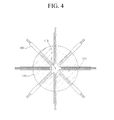
- FIG. 4 is a top view schematically showing a form in which heaters are inserted into a first temperature measuring part in the gauge for measuring 2-dimensional heat flux of FIG. 1
- FIG. 5 is a side view schematically showing the first temperature measuring part in the gauge for measuring 2-dimensional heat flux of FIG. 1 .
- the gauge 100 for measuring 2-dimensional heat flux which is used to measure heat transfer characteristics of a thick plate passing through an accelerated cooling device in an accelerated cooling process of the thick plate, is configured to include a first temperature measuring part 110, a second temperature measuring part 120, heaters 140, and a temperature sensor part 150.
- the gauge for measuring 2-dimensional heat flux may be used as a means for testing cooling characteristics of the accelerated cooling device before an actual accelerated cooling process of the thick plate.
- the first temperature measuring part 110 is provided with different measuring points spaced apart from each other in a thickness direction, and is provided with heater insertion holes 111 into which heaters 140 to be described below are inserted and a first insertion groove part 112 into which the temperature sensor part 150 is inserted.
- the gauge 100 for measuring 2-dimensional heat flux according to a first exemplary embodiment of the present invention has a cylindrical shape, but is not limited thereto.
- the first temperature measuring part 110 may be made of the same material as that of the thick plate, but is preferably made of stainless steel in order to improve durability of measurement and minimize additional thermal consideration factors by transformation heat generation generated in general carbon steel.
- the first temperature measuring part is made of a stainless steel (SUS) material having a low coefficient of thermal expansion, but is not limited thereto.
- the heater insertion holes 111 are provided so that heaters 140 to be described below are inserted therein, and are formed in a central direction along an outer surface.
- the heat insertion holes 111 are arranged so that four heater insertion holes 111 form one layer and form equal angles.
- heater insertion holes 111 neighboring each other in a vertical direction are installed so as to form an angle of 45 degrees therebetween. This arrangement is used to heat the first temperature measuring part 110 to a uniform temperature by the heaters 140 that are to be inserted into the heat insertion holes 111.
- the first insertion groove part 112 is configured so that temperature sensors 151 configuring a temperature sensor part 150 to be described below are inserted therein, thereby making it possible to allow temperatures of the measuring points of the first temperature measuring part 110 to be measured.
- a plurality of insertion grooves configuring the first insertion groove part 112 are formed so as to be spaced apart from each other in the thickness direction of the first temperature measuring part 110 and have the same depth in the central direction.
- heat flux may be measured using a temperature difference and a distance difference between insertion grooves formed in second or third temperature measuring parts 120 or 130 to be described below. Therefore, the present invention is not limited to the number of insertion grooves.
- the insertion grooves of the first insertion groove part 112 are preferably inserted up to the center of the first temperature measuring part 110 so as to accurately measure heat flux in a thickness direction to be described below, but are not limited thereto.
- the second temperature measuring part 120 is provided on the first temperature measuring part 110 and includes a second insertion groove part 121 formed therein so as to measure heat flux of the thick plate in a radial direction. It is preferable that insertion grooves of the second insertion groove part 121 have different depths from different positions on an outer surface, are spaced apart from each other in a circumferential direction in the central direction, and are formed at intervals corresponding to equal angles so as to not have an influence on each other.
- a transverse cross-section of the second temperature measuring part 120 has a polygonal shape in order to easily manufacture the second insertion groove part 121 having the arrangement as described above and easily measure a central axis 113 of the second temperature measuring part 120.
- the transverse cross-section of the second temperature measuring part 120 has an octagonal shape. This is because eight measuring points of the second temperature measuring part 120 are selected. That is, the number of sides of the polygonal shape is the same as the number of measuring points in the second temperature measuring part 120. For example, when there are four measuring points, it is preferable that the transverse cross-section of the second temperature measuring part 120 has a square shape.
- the second insertion groove part 121 is formed of a plurality of insertion grooves spaced apart from each other in the circumferential direction along an outer surface of the second temperature measuring part and having different depths in the central direction, and is configured so that temperature sensors 151 configuring the temperature sensor part 150 to be described below are inserted therein, thereby making it possible to allow temperatures of the measuring points of the second temperature measuring part 120 to be measured.
- the second insertion groove part 121 is formed of one insertion groove, such that one insertion groove changes measuring points at each of different depths, thereby making it possible to measure temperatures.
- the second insertion groove part is formed of one insertion groove, it is difficult to accurately measure temperatures of the measuring points. Therefore, it is preferable that the plurality of insertion grooves having different depths are formed so as to be spaced apart from each other along the outer surface.
- the gauge 100 for measuring 2-dimensional heat flux according to a first exemplary embodiment of the present invention, seven insertion grooves are formed at the centers of seven surfaces except for a measuring point provided in order to measure a temperature of a surface among eight surfaces formed on the outer surface of the second temperature measuring part 120.
- the temperature sensors 151 of the temperature sensor part 150 are inserted into the seven insertion grooves, respectively, to measure temperatures of distal end portions of the insertion grooves.
- the heaters 140 are detachably inserted into the heater insertion holes 111 to uniformly heat the first temperature measuring part 110 and the second temperature measuring part 120.
- the heater 140 is a cartridge heater, but is not limited thereto.
- the cartridge heater used as the heater 140 which is an apparatus inserted into an insertion hole formed in a mold used in a press or a thermoformer and is mainly used to transfer heat emitted by an electric heat coil, thereby heating a limited space part in the mold, has a cylindrical shape in an exemplary embodiment of the present invention.
- temperatures of the first temperature measuring part 110 and the second temperature measuring part 120 heated by the heaters 140 become about 900 °C corresponding to a temperature at which the thick plate generally starts to be cooled in the accelerated cooling process.
- the temperature sensor part 150 is formed of a plurality of temperature sensors 151, and is used to sense the temperatures of the first temperature measuring part 110 and the second temperature measuring part 120 in the accelerated cooling process.
- the plurality of temperature sensors 151 are inserted into the insertion grooves formed in the first temperature measuring part 110 and the second temperature measuring part 120, respectively, to sense temperatures of distal end portions of the insertion grooves.
- the temperature sensor 151 is a thermocouple, but is not limited thereto.
- the second temperature measuring part 120 is provided on the first temperature measuring part 110 and that the first temperature measuring part 110 and the second temperature measuring part 120 are installed so that central axes thereof are the same.
- the first temperature measuring part 110 and the second temperature measuring part 120 may be formed integrally with each other so that the axes thereof are the same, but are not limited thereto.
- the temperature sensors 151 are installed so as to be completely inserted into the insertion grooves of the first insertion groove part 112 or the second insertion groove part 121 to measure the temperatures of the measuring points of the first temperature measuring part 110 or the second temperature measuring part 120.
- empty spaces of the insertion grooves into which the temperature sensors 151 are inserted are filled with the same metal material as that of the second temperature measuring part 120 in order to prevent heat flow from being hindered by empty spaces in which the insertion grooves are formed.
- the empty spaces of the insertion grooves may be filled by a laser welding method, but are not limited thereto.
- the temperature sensors 151 may be manufactured in a state in which they are inserted into the first temperature measuring part 110 or the second temperature measuring part 120 at the beginning, but is not limited thereto.
- the first temperature measuring part 110 and the second temperature measuring part 120 are heated to generally uniform temperatures by the plurality of heaters 140 installed in the first temperature measuring part 110, and it is preferable that the heated temperatures become about 900 °C corresponding to a temperature at which the thick plate generally starts to be cooled in the accelerated cooling process.
- the temperatures of the distal end portions of the respective insertion grooves are measured by the temperature sensors 151 installed in the respective insertion grooves.
- An insertion groove provided in the second insertion groove part 121 in order to measure a central temperature of the second temperature measuring part 120 is selected as a first measuring point 122, and any one of the insertion grooves except for the first measuring point 122 is selected as a second measuring point 123 to calculate heat flux of the second temperature measuring part 120 in the radial direction using a temperature difference and a distance difference between the first measuring point 122 and the second measuring point 123.
- the heat flux in the radial direction as described above may be calculated by a 2-dimenional inverse heat conduction method through the temperature measured by the second temperature measuring part 120 and the temperature measured by the first temperature measuring part 110.
- the first measuring point 122 it is ideal for the first measuring point 122 to be positioned on an upper surface of the second temperature measuring part 120 in order to measure the heat flux of the second temperature measuring part 120.
- the temperature sensor 151 is exposed to the outside to hinder a fluid flow, such that heat flow data in a normal environment may not be obtained. Therefore, the second insertion groove part 121 including the first measuring point 122 is not exposed to the upper surface of the second temperature measuring part 120.
- a point at which the second insertion groove part 121 is installed is close to the upper surface of the second temperature measuring part 120, it may be considered that the point is substantially the same as the upper surface of the second temperature measuring part 120.
- water jet is provided as a fluid having a lower temperature than those of the first temperature measuring part 110 and the second temperature measuring part 120 heated by the heaters 140 and sprayed in an exemplary embodiment of the present invention in order to cool the first temperature measuring part 110 and the second temperature measuring part 120, the present invention is not limited thereto.
- FIG. 6 is a perspective view schematically showing a gauge for measuring 2-dimensional heat flux according to a second exemplary embodiment of the present invention
- FIG. 7 is a front view schematically showing the gauge for measuring 2-dimensional heat flux of FIG. 6
- FIG. 8 is a cross-sectional view schematically showing a form in which an auxiliary insertion groove part and an auxiliary temperature sensor part are installed in a first temperature measuring part in the gauge for measuring 2-dimensional heat flux of FIG. 6
- FIG. 9 is a top view schematically showing a third temperature measuring part in the gauge for measuring 2-dimensional heat flux of FIG. 6 .
- the gauge 200 for measuring 2-dimensional heat flux is configured to include a first temperature measuring part 210, a second temperature measuring part 220, a third temperature measuring part 230, heaters 240, and a temperature sensor part 250.
- the first temperature measuring part 210 includes heater insertion holes 211 into which the heaters 240 are inserted, a first insertion groove part 212 provided in order to measure heat flux in the thickness direction, and an auxiliary insertion groove part 214 provided in order to measure heat flux in the radial direction.
- the auxiliary insertion groove part 214 is configured so that temperature sensors 251 configuring the temperature sensor part 250 are inserted therein, thereby allowing temperatures at measuring points disposed at different positions on an outer surface of the first temperature measuring part 210 and spaced apart from each other in the circumferential direction to be measured to allow heat flux of the first temperature measuring part 210 in the radial direction to be measured.
- the auxiliary insertion groove part 214 includes a plurality of insertion grooves depressed in the central direction and formed so as to be spaced apart from each other along the outer surface of the first temperature measuring part 210.
- the auxiliary insertion groove part 214 may include one of the insertion grooves of the first insertion groove part 212 and select one of the insertion grooves of the first insertion groove part 212 as a third measuring point 215.
- the third temperature measuring part 230 is provided beneath the first temperature measuring part 210, and includes a third insertion groove part 231 formed therein so as to measure heat flux of the thick plate in the radial direction. It is preferable that insertion grooves of the third insertion groove part 231 are formed at intervals corresponding to equal angles so as not to have an influence on each other, and it is preferable that a transverse cross-section of the third temperature measuring part 230 has a polygonal shape in order to easily manufacture the third insertion groove part 231 having the arrangement as described above and easily measure a central axis 213 of the third temperature measuring part 230. Since configurations of the third temperature measuring part 230 other than the above-mentioned configurations are the same as those of the second temperature measuring part 220, a detailed description thereof will be omitted.
- Heat flux of the first temperature measuring part 210 in the radial direction may be measured by the above-mentioned 2-dimensional inverse heat conduction method.
- An insertion groove provided in the auxiliary insertion groove part 214 in order to measure a central temperature of the first temperature measuring part 210 is selected as the third measuring point 215, and any one of the insertion grooves except for the third measuring point 215 is selected as a fourth measuring point 216 to calculate the heat flux of the first temperature measuring part 210 in the radial direction using a temperature difference and a distance difference between the third measuring point 215 and the fourth measuring point 216.
- heat flux of the third temperature measuring part 230 in the radial direction may also be measured by the above-mentioned 2-dimensional inverse heat conduction method.
- An insertion groove provided in the third insertion groove part 231 in order to measure a central temperature of the third temperature measuring part 230 is selected as a fifth measuring point 232, and any one of the insertion grooves except for the fifth measuring point 232 is selected as a sixth measuring point 233 to calculate the heat flux of the third temperature measuring part 230 in the radial direction using a temperature difference and a distance difference between the fifth measuring point 232 and the sixth measuring point 233.
- heat flux in the thickness direction may be measured by the above-mentioned 2-dimensional inverse heat conduction method using a temperature difference and a distance difference between the first measuring point 122 and the fifth measuring point 232, and the heat flux in the thickness direction as described above may be considered as heat flux from an upper surface of the thick plate to a lower surface thereof.
Landscapes
- Engineering & Computer Science (AREA)
- Chemical & Material Sciences (AREA)
- Combustion & Propulsion (AREA)
- Physics & Mathematics (AREA)
- General Physics & Mathematics (AREA)
- Mechanical Engineering (AREA)
- Measuring Temperature Or Quantity Of Heat (AREA)
Abstract
Description
- The present invention relates to a gauge for measuring 2-dimensional heat flux. More particularly, the present invention relates to a gauge for measuring 2-dimensional heat flux that is capable of measuring heat flux of a thick plate in a thickness direction and a radial direction, and a method for measuring 2-dimensional heat flux using the same.
- Generally, a metal plate having a thickness of 6 mm or more is called a thick plate. This thick plate is manufactured by a rolling process of rolling a slab heated to a high temperature so as to have a target thickness and width by a rolling mill and an accelerated cooling process of cooling upper and lower surfaces of the thick plate using an accelerated cooling device of the thick plate during cooling of the thick plate in order to control a temperature difference between head and tail portions of the thick plate.
- The thick plate is subjected to heat movement and plastic deformation processes in the above-mentioned rolling process and accelerated cooling process. These processes have a significant influence on shape quality of a thick plate product such as plate deformation as well as physical properties of a thick plate material. When considering this, cooling heat transfer characteristics at a high temperature such as surface temperature, heat flux, and a heat transfer coefficient in the accelerated cooling process should be able to be accurately measured in order to manufacture a thick plate having desired characteristics.
- In this accelerated cooling process, a steel plate needs to be cooled in a short time so that a surface temperature thereof is decreased from about 900 °C to about 400 °C, and effective cooling control is required in order to minimize thermal deformation of the steel plate occurring by a temperature deviation.
- According to the related art, an effort to recognize changes in surface and internal temperatures of the steel plate depending on a change in time and heat transfer characteristics in the accelerated cooling process by installing a contact type of sensor or a non-contact type of sensor in an accelerated cooling device performing the accelerated cooling process in order for the accelerated cooling device to perform cooling control has been conducted.
- A typical example of the contact type of sensor installed in the accelerated cooling device in order to recognize the heat transfer characteristics in the accelerated cooling device may include a thermocouple. In the case in which the thermocouple is installed on a surface of the thick plate, a change in fluid flow and a change in a boiling phenomenon occur by the installed thermocouple itself to cause a change in measurement of a surface temperature. Since a large error occurs in temperature measurement due to radiation, particularly at a high temperature, the surface temperature of the thick plate in the accelerated cooling process may not be accurately measured using the contact type of sensor.
- In the case of measurement using the non-contact type of sensor such as an infrared thermometer, direct measurement is impossible due to a flow of excessive steam and water jet and an influence of remaining water.
- The above information disclosed in this Background section is only for enhancement of understanding of the background of the invention and therefore it may contain information that does not form the prior art that is already known in this country to a person of ordinary skill in the art.
- The present invention has been made in an effort to provide a gauge for measuring 2-dimensional heat flux that is capable of measuring heat flux of a thick plate in a radial direction by measuring temperatures at points depressed from a second temperature measuring part in a central direction so as to have different depths and measuring heat flux of the thick plate in a thickness direction by measuring temperatures at different points formed in the thickness direction, using 2-dimenional inverse heat conduction method for determining heat flux of a surface from abnormal temperature distribution in a solid, and a method for measuring 2-dimensional heat flux using the same.
- An exemplary embodiment of the present invention provides a gauge for measuring 2-dimensional heat flux, including: a first temperature measuring part including a plurality of different measuring points spaced apart from each other in a thickness direction; a second temperature measuring part provided on one end portion of the first temperature measuring part and including a plurality of different measuring points spaced apart from each other in a circumferential direction; and heaters installed in the first temperature measuring part and heating the first temperature measuring part and the second temperature measuring part.
- The first temperature measuring part may be provided with a first insertion groove part formed of a plurality of insertion grooves having the same depth from different positions on an outer surface, spaced apart from each other in the thickness direction, in a central direction, the second temperature measuring part may be provided with a second insertion groove part formed of a plurality of insertion grooves having different depths from different positions on an outer surface, spaced apart from each other in the circumferential direction, in the central direction, and the gauge for measuring 2-dimensional heat flux may further include a temperature sensor part inserted into the insertion grooves of the first insertion groove part or the second insertion groove part and measuring temperatures at the measuring points.
- The gauge for measuring 2-dimensional heat flux may further include a third temperature measuring part provided on the other end portion of the first temperature measuring part and provided with a third insertion groove part formed of a plurality of insertion grooves having different depths from different positions on an outer surface, spaced apart from each other in the circumferential direction, in the central direction.
- A transverse cross-section of the second temperature measuring part or the third temperature measuring part may have a polygonal shape.
- The first temperature measuring part may include a plurality of different measuring points spaced apart from each other in the circumferential direction.
- The first temperature measuring part may be provided with an auxiliary insertion groove part neighboring the second insertion groove part in the thickness direction and formed of a plurality of insertion grooves having different depths in the circumferential direction, and the gauge for measuring 2-dimensional heat flux may further include an auxiliary temperature sensor part inserted into the insertion grooves of the auxiliary insertion groove part and measuring a temperature of the auxiliary insertion groove part.
- A plurality of heaters forming one layer may be installed in a plurality of layers on sides of the first temperature measuring part, wherein the heaters installed in each layer may be arranged at equal angles, and the heaters installed in neighboring layers are arranged at intervals of 45 degrees in order to uniformly heat the first temperature measuring part.
- According to an exemplary embodiment of the present invention, a gauge for measuring 2-dimensional heat flux that is capable of measuring heat flux in a thickness direction using temperatures measured at two different measuring points in the thickness direction of a thick plate and that is capable of measuring heat flux in a radial direction using temperatures at two measuring points spaced apart from each other along an outer surface of the thick plate and having different depths may be provided.
- In addition, temperatures of a second temperature measuring part corresponding to an upper surface of the thick plate and a third temperature measuring part corresponding to a lower surface of the thick plate are measured, thereby making it possible to simultaneously measure cooling characteristics of the upper and lower surfaces of the thick plate.
- Further, a transverse cross-section of the second temperature measuring part has a polygonal shape, such that positions of insertion grooves in which temperature sensor parts are to be installed may be easily measured, thereby making it possible to significantly improve accuracy of heat flow data that may be obtained by the gauge for measuring 2-dimensional heat flux.
- Further, the heat flux of the second temperature measuring part in the radial direction may be measured, such that heat flow data at the time of actually acceleration-cooling the thick plate may be measured.
- Furthermore, a first temperature measuring part may be heated so as to have a uniform temperature by heaters that are regularly arranged, such that the gauge for measuring 2-dimensional heat flux is provided in the same state as that of the thick plate, thereby making it possible to significantly improve accuracy of heat flow data that may be obtained by the gauge for measuring 2-dimensional heat flux.
-
-
FIG. 1 is a perspective view schematically showing a gauge for measuring 2-dimensional heat flux according to a first exemplary embodiment of the present invention. -
FIG. 2 is an exploded perspective view schematically showing the gauge for measuring 2-dimensional heat flux ofFIG. 1 . -
FIG. 3 is a top view schematically showing a second temperature measuring part in the gauge for measuring 2-dimensional heat flux ofFIG. 1 . -
FIG. 4 is a top view schematically showing a form in which heaters are inserted into a first temperature measuring part in the gauge for measuring 2-dimensional heat flux ofFIG. 1 . -
FIG. 5 is a side view schematically showing the first temperature measuring part in the gauge for measuring 2-dimensional heat flux ofFIG. 1 . -
FIG. 6 is a perspective view schematically showing a gauge for measuring 2-dimensional heat flux according to a second exemplary embodiment of the present invention. -
FIG. 7 is a front view schematically showing the gauge for measuring 2-dimensional heat flux ofFIG. 6 . -
FIG. 8 is a cross-sectional view schematically showing a form in which an auxiliary insertion groove part and an auxiliary temperature sensor part are installed in a first temperature measuring part in the gauge for measuring 2-dimensional heat flux ofFIG. 6 . -
FIG. 9 is a top view schematically showing a third temperature measuring part in the gauge for measuring 2-dimensional heat flux ofFIG. 6 . - Prior to describing the present invention, in several exemplary embodiments, components having the same configuration will be representatively described using the same reference numeral in a first exemplary embodiment, and components different from those of a first exemplary embodiment will be described in the other exemplary embodiments.
- Hereinafter, a gauge for measuring 2-dimensional heat flux according to exemplary embodiments of the present invention will be described with reference to the accompanying drawings.
-
FIG. 1 is a perspective view schematically showing a gauge for measuring 2-dimensional heat flux according to a first exemplary embodiment of the present invention,FIG. 2 is an exploded perspective view schematically showing the gauge for measuring 2-dimensional heat flux ofFIG. 1 ,FIG. 3 is a top view schematically showing a second temperature measuring part in the gauge for measuring 2-dimensional heat flux ofFIG. 1 ,FIG. 4 is a top view schematically showing a form in which heaters are inserted into a first temperature measuring part in the gauge for measuring 2-dimensional heat flux ofFIG. 1 , andFIG. 5 is a side view schematically showing the first temperature measuring part in the gauge for measuring 2-dimensional heat flux ofFIG. 1 . - Referring to
FIGS. 1 to 5 , thegauge 100 for measuring 2-dimensional heat flux according to a first exemplary embodiment of the present invention, which is used to measure heat transfer characteristics of a thick plate passing through an accelerated cooling device in an accelerated cooling process of the thick plate, is configured to include a firsttemperature measuring part 110, a secondtemperature measuring part 120,heaters 140, and atemperature sensor part 150. The gauge for measuring 2-dimensional heat flux may be used as a means for testing cooling characteristics of the accelerated cooling device before an actual accelerated cooling process of the thick plate. - The first
temperature measuring part 110 is provided with different measuring points spaced apart from each other in a thickness direction, and is provided withheater insertion holes 111 into whichheaters 140 to be described below are inserted and a firstinsertion groove part 112 into which thetemperature sensor part 150 is inserted. Thegauge 100 for measuring 2-dimensional heat flux according to a first exemplary embodiment of the present invention has a cylindrical shape, but is not limited thereto. - The first
temperature measuring part 110 may be made of the same material as that of the thick plate, but is preferably made of stainless steel in order to improve durability of measurement and minimize additional thermal consideration factors by transformation heat generation generated in general carbon steel. In an exemplary embodiment of the present invention, the first temperature measuring part is made of a stainless steel (SUS) material having a low coefficient of thermal expansion, but is not limited thereto. - Referring to
FIG. 4 , theheater insertion holes 111 are provided so thatheaters 140 to be described below are inserted therein, and are formed in a central direction along an outer surface. In order for the firsttemperature measuring part 110 and the secondtemperature measuring part 120 to be efficiently heated by theheaters 140, theheat insertion holes 111 are arranged so that fourheater insertion holes 111 form one layer and form equal angles. In addition,heater insertion holes 111 neighboring each other in a vertical direction are installed so as to form an angle of 45 degrees therebetween. This arrangement is used to heat the firsttemperature measuring part 110 to a uniform temperature by theheaters 140 that are to be inserted into theheat insertion holes 111. - Referring to
FIG. 5 , the firstinsertion groove part 112 is configured so thattemperature sensors 151 configuring atemperature sensor part 150 to be described below are inserted therein, thereby making it possible to allow temperatures of the measuring points of the firsttemperature measuring part 110 to be measured. In thegauge 100 for measuring 2-dimensional heat flux according to a first exemplary embodiment of the present invention, a plurality of insertion grooves configuring the firstinsertion groove part 112 are formed so as to be spaced apart from each other in the thickness direction of the firsttemperature measuring part 110 and have the same depth in the central direction. However, even if one insertion groove is formed, heat flux may be measured using a temperature difference and a distance difference between insertion grooves formed in second or thirdtemperature measuring parts 120 or 130 to be described below. Therefore, the present invention is not limited to the number of insertion grooves. - In addition, the insertion grooves of the first
insertion groove part 112 are preferably inserted up to the center of the firsttemperature measuring part 110 so as to accurately measure heat flux in a thickness direction to be described below, but are not limited thereto. - Referring to
FIG. 3 , the secondtemperature measuring part 120 is provided on the firsttemperature measuring part 110 and includes a secondinsertion groove part 121 formed therein so as to measure heat flux of the thick plate in a radial direction. It is preferable that insertion grooves of the secondinsertion groove part 121 have different depths from different positions on an outer surface, are spaced apart from each other in a circumferential direction in the central direction, and are formed at intervals corresponding to equal angles so as to not have an influence on each other. - In addition, it is preferable that a transverse cross-section of the second
temperature measuring part 120 has a polygonal shape in order to easily manufacture the secondinsertion groove part 121 having the arrangement as described above and easily measure acentral axis 113 of the secondtemperature measuring part 120. - In the
gauge 100 for measuring 2-dimensional heat flux according to a first exemplary embodiment of the present invention, the transverse cross-section of the secondtemperature measuring part 120 has an octagonal shape. This is because eight measuring points of the secondtemperature measuring part 120 are selected. That is, the number of sides of the polygonal shape is the same as the number of measuring points in the secondtemperature measuring part 120. For example, when there are four measuring points, it is preferable that the transverse cross-section of the secondtemperature measuring part 120 has a square shape. - The second
insertion groove part 121 is formed of a plurality of insertion grooves spaced apart from each other in the circumferential direction along an outer surface of the second temperature measuring part and having different depths in the central direction, and is configured so thattemperature sensors 151 configuring thetemperature sensor part 150 to be described below are inserted therein, thereby making it possible to allow temperatures of the measuring points of the secondtemperature measuring part 120 to be measured. - Alternatively, the second
insertion groove part 121 is formed of one insertion groove, such that one insertion groove changes measuring points at each of different depths, thereby making it possible to measure temperatures. However, when the second insertion groove part is formed of one insertion groove, it is difficult to accurately measure temperatures of the measuring points. Therefore, it is preferable that the plurality of insertion grooves having different depths are formed so as to be spaced apart from each other along the outer surface. - In the
gauge 100 for measuring 2-dimensional heat flux according to a first exemplary embodiment of the present invention, seven insertion grooves are formed at the centers of seven surfaces except for a measuring point provided in order to measure a temperature of a surface among eight surfaces formed on the outer surface of the secondtemperature measuring part 120. Thetemperature sensors 151 of thetemperature sensor part 150 are inserted into the seven insertion grooves, respectively, to measure temperatures of distal end portions of the insertion grooves. - The
heaters 140 are detachably inserted into the heater insertion holes 111 to uniformly heat the firsttemperature measuring part 110 and the secondtemperature measuring part 120. According to an exemplary embodiment of the present invention, theheater 140 is a cartridge heater, but is not limited thereto. - The cartridge heater used as the
heater 140, which is an apparatus inserted into an insertion hole formed in a mold used in a press or a thermoformer and is mainly used to transfer heat emitted by an electric heat coil, thereby heating a limited space part in the mold, has a cylindrical shape in an exemplary embodiment of the present invention. - In addition, temperatures of the first
temperature measuring part 110 and the secondtemperature measuring part 120 heated by theheaters 140 become about 900 °C corresponding to a temperature at which the thick plate generally starts to be cooled in the accelerated cooling process. - The
temperature sensor part 150 is formed of a plurality oftemperature sensors 151, and is used to sense the temperatures of the firsttemperature measuring part 110 and the secondtemperature measuring part 120 in the accelerated cooling process. The plurality oftemperature sensors 151 are inserted into the insertion grooves formed in the firsttemperature measuring part 110 and the secondtemperature measuring part 120, respectively, to sense temperatures of distal end portions of the insertion grooves. In thegauge 100 for measuring 2-dimensional heat flux according to a first exemplary embodiment of the present invention, thetemperature sensor 151 is a thermocouple, but is not limited thereto. - Again describing a coupled relationship between the first
temperature measuring part 110 and the secondtemperature measuring part 120, it is preferable that the secondtemperature measuring part 120 is provided on the firsttemperature measuring part 110 and that the firsttemperature measuring part 110 and the secondtemperature measuring part 120 are installed so that central axes thereof are the same. The firsttemperature measuring part 110 and the secondtemperature measuring part 120 may be formed integrally with each other so that the axes thereof are the same, but are not limited thereto. - Again describing a coupled relationship between the first
insertion groove part 112 or the secondinsertion groove part 121 and thetemperature sensors 151, thetemperature sensors 151 are installed so as to be completely inserted into the insertion grooves of the firstinsertion groove part 112 or the secondinsertion groove part 121 to measure the temperatures of the measuring points of the firsttemperature measuring part 110 or the secondtemperature measuring part 120. - In addition, it is preferable that empty spaces of the insertion grooves into which the
temperature sensors 151 are inserted are filled with the same metal material as that of the secondtemperature measuring part 120 in order to prevent heat flow from being hindered by empty spaces in which the insertion grooves are formed. The empty spaces of the insertion grooves may be filled by a laser welding method, but are not limited thereto. Further, in addition to a method for filling the empty spaces later, thetemperature sensors 151 may be manufactured in a state in which they are inserted into the firsttemperature measuring part 110 or the secondtemperature measuring part 120 at the beginning, but is not limited thereto. - Next, a method for measuring heat flux using the
gauge 100 for measuring 2-dimensional heat flux according to a first exemplary embodiment of the present invention described above will be described. - The first
temperature measuring part 110 and the secondtemperature measuring part 120 are heated to generally uniform temperatures by the plurality ofheaters 140 installed in the firsttemperature measuring part 110, and it is preferable that the heated temperatures become about 900 °C corresponding to a temperature at which the thick plate generally starts to be cooled in the accelerated cooling process. - After the first
temperature measuring part 110 and the secondtemperature measuring part 120 are sufficiently heated by theheaters 140, the temperatures of the distal end portions of the respective insertion grooves are measured by thetemperature sensors 151 installed in the respective insertion grooves. - An insertion groove provided in the second
insertion groove part 121 in order to measure a central temperature of the secondtemperature measuring part 120 is selected as afirst measuring point 122, and any one of the insertion grooves except for thefirst measuring point 122 is selected as asecond measuring point 123 to calculate heat flux of the secondtemperature measuring part 120 in the radial direction using a temperature difference and a distance difference between thefirst measuring point 122 and thesecond measuring point 123. The heat flux in the radial direction as described above may be calculated by a 2-dimenional inverse heat conduction method through the temperature measured by the secondtemperature measuring part 120 and the temperature measured by the firsttemperature measuring part 110. - It is ideal for the
first measuring point 122 to be positioned on an upper surface of the secondtemperature measuring part 120 in order to measure the heat flux of the secondtemperature measuring part 120. However, in this case, thetemperature sensor 151 is exposed to the outside to hinder a fluid flow, such that heat flow data in a normal environment may not be obtained. Therefore, the secondinsertion groove part 121 including thefirst measuring point 122 is not exposed to the upper surface of the secondtemperature measuring part 120. However, since a point at which the secondinsertion groove part 121 is installed is close to the upper surface of the secondtemperature measuring part 120, it may be considered that the point is substantially the same as the upper surface of the secondtemperature measuring part 120. - Although water jet is provided as a fluid having a lower temperature than those of the first
temperature measuring part 110 and the secondtemperature measuring part 120 heated by theheaters 140 and sprayed in an exemplary embodiment of the present invention in order to cool the firsttemperature measuring part 110 and the secondtemperature measuring part 120, the present invention is not limited thereto. - Next, a
gauge 200 for measuring 2-dimensional heat flux according to a second exemplary embodiment of the present invention will be described. -
FIG. 6 is a perspective view schematically showing a gauge for measuring 2-dimensional heat flux according to a second exemplary embodiment of the present invention,FIG. 7 is a front view schematically showing the gauge for measuring 2-dimensional heat flux ofFIG. 6 ,FIG. 8 is a cross-sectional view schematically showing a form in which an auxiliary insertion groove part and an auxiliary temperature sensor part are installed in a first temperature measuring part in the gauge for measuring 2-dimensional heat flux ofFIG. 6 , andFIG. 9 is a top view schematically showing a third temperature measuring part in the gauge for measuring 2-dimensional heat flux ofFIG. 6 . - Referring to
FIGS. 6 to 9 , thegauge 200 for measuring 2-dimensional heat flux according to a second exemplary embodiment of the present invention is configured to include a firsttemperature measuring part 210, a secondtemperature measuring part 220, a thirdtemperature measuring part 230,heaters 240, and atemperature sensor part 250. - The first
temperature measuring part 210 includes heater insertion holes 211 into which theheaters 240 are inserted, a firstinsertion groove part 212 provided in order to measure heat flux in the thickness direction, and an auxiliaryinsertion groove part 214 provided in order to measure heat flux in the radial direction. - The auxiliary
insertion groove part 214 is configured so thattemperature sensors 251 configuring thetemperature sensor part 250 are inserted therein, thereby allowing temperatures at measuring points disposed at different positions on an outer surface of the firsttemperature measuring part 210 and spaced apart from each other in the circumferential direction to be measured to allow heat flux of the firsttemperature measuring part 210 in the radial direction to be measured. The auxiliaryinsertion groove part 214 includes a plurality of insertion grooves depressed in the central direction and formed so as to be spaced apart from each other along the outer surface of the firsttemperature measuring part 210. In thegauge 200 for measuring 2-dimensional heat flux according to a second exemplary embodiment of the present invention, the auxiliaryinsertion groove part 214 may include one of the insertion grooves of the firstinsertion groove part 212 and select one of the insertion grooves of the firstinsertion groove part 212 as athird measuring point 215. - The third
temperature measuring part 230 is provided beneath the firsttemperature measuring part 210, and includes a thirdinsertion groove part 231 formed therein so as to measure heat flux of the thick plate in the radial direction. It is preferable that insertion grooves of the thirdinsertion groove part 231 are formed at intervals corresponding to equal angles so as not to have an influence on each other, and it is preferable that a transverse cross-section of the thirdtemperature measuring part 230 has a polygonal shape in order to easily manufacture the thirdinsertion groove part 231 having the arrangement as described above and easily measure acentral axis 213 of the thirdtemperature measuring part 230. Since configurations of the thirdtemperature measuring part 230 other than the above-mentioned configurations are the same as those of the secondtemperature measuring part 220, a detailed description thereof will be omitted. - Next, a method for measuring heat flux using the
gauge 200 for measuring 2-dimensional heat flux according to the second exemplary embodiment of the present invention described above will be described. - Heat flux of the first
temperature measuring part 210 in the radial direction may be measured by the above-mentioned 2-dimensional inverse heat conduction method. An insertion groove provided in the auxiliaryinsertion groove part 214 in order to measure a central temperature of the firsttemperature measuring part 210 is selected as thethird measuring point 215, and any one of the insertion grooves except for thethird measuring point 215 is selected as afourth measuring point 216 to calculate the heat flux of the firsttemperature measuring part 210 in the radial direction using a temperature difference and a distance difference between thethird measuring point 215 and thefourth measuring point 216. - In addition, heat flux of the third
temperature measuring part 230 in the radial direction may also be measured by the above-mentioned 2-dimensional inverse heat conduction method. An insertion groove provided in the thirdinsertion groove part 231 in order to measure a central temperature of the thirdtemperature measuring part 230 is selected as afifth measuring point 232, and any one of the insertion grooves except for thefifth measuring point 232 is selected as asixth measuring point 233 to calculate the heat flux of the thirdtemperature measuring part 230 in the radial direction using a temperature difference and a distance difference between thefifth measuring point 232 and thesixth measuring point 233. - In addition, heat flux in the thickness direction may be measured by the above-mentioned 2-dimensional inverse heat conduction method using a temperature difference and a distance difference between the
first measuring point 122 and thefifth measuring point 232, and the heat flux in the thickness direction as described above may be considered as heat flux from an upper surface of the thick plate to a lower surface thereof. - The scope of the present invention is not limited to the above-mentioned exemplary embodiment, but may be implemented in various forms that fall within the claims. The present invention may be variously modified by those skilled in the art to which the present invention pertains without departing from the gist of the present invention as defined by the claims. In addition, these modifications are to fall within the scope of the following claims.
-
- 100:
- gauge for measuring 2-dimensional heat flux
- 110:
- first temperature measuring part
- 111:
- heater insertion hole
- 112:
- first insertion groove part
- 113:
- central axis
- 120:
- second temperature measuring part
- 121:
- second insertion groove part
- 122:
- first measuring point
- 123:
- second measuring point
- 140:
- heater
- 150:
- temperature sensor part
- 151:
- temperature sensor
- 200:
- gauge for measuring 2-dimensional heat flux
- 210:
- first temperature measuring part
- 211:
- heater insertion hole
- 212:
- first insertion groove part
- 213:
- central axis
- 214:
- auxiliary insertion groove part
- 215:
- third measuring point
- 216:
- fourth measuring point
- 220:
- second temperature measuring part
- 221:
- second insertion groove part
- 222:
- first measuring point
- 223:
- second measuring point
- 230:
- third temperature measuring part
- 231:
- third insertion groove part
- 232:
- fifth measuring point
- 233:
- sixth measuring point
- 240:
- heater
- 250:
- temperature sensor part
- 251:
- temperature sensor
Claims (7)
- A gauge for measuring 2-dimensional heat flux, comprising:a first temperature measuring part including a plurality of different measuring points spaced apart from each other in a thickness direction;a second temperature measuring part provided on one end portion of the first temperature measuring part and including a plurality of different measuring points spaced apart from each other in a circumferential direction; andheaters installed in the first temperature measuring part and heating the first temperature measuring part and the second temperature measuring part.
- The gauge for measuring 2-dimensional heat flux of claim 1, wherein
the first temperature measuring part is provided with a first insertion groove part formed of a plurality of insertion grooves having the same depth from different positions on an outer surface, spaced apart from each other in the thickness direction, in a central direction,
the second temperature measuring part is provided with a second insertion groove part formed of a plurality of insertion grooves having different depths from different positions on an outer surface, spaced apart from each other in the circumferential direction, in the central direction, and
the gauge for measuring 2-dimensional heat flux further comprising a temperature sensor part inserted into the insertion grooves of the first insertion groove part or the second insertion groove part and measuring temperatures at the measuring points. - The gauge for measuring 2-dimensional heat flux of claim 2, further comprising
a third temperature measuring part provided on the other end portion of the first temperature measuring part and provided with a third insertion groove part formed of a plurality of insertion grooves having different depths from different positions on an outer surface, spaced apart from each other in the circumferential direction, in the central direction. - The gauge for measuring 2-dimensional heat flux of claim 3, wherein
a transverse cross-section of the second temperature measuring part or the third temperature measuring part has a polygonal shape. - The gauge for measuring 2-dimensional heat flux of claim 1, wherein
the first temperature measuring part includes a plurality of different measuring points spaced apart from each other in the circumferential direction. - The gauge for measuring 2-dimensional heat flux of claim 5, wherein
the first temperature measuring part is provided with an auxiliary insertion groove part neighboring the second insertion groove part in the thickness direction and formed of a plurality of insertion grooves having different depths in the circumferential direction, and
the gauge for measuring 2-dimensional heat flux further comprises an auxiliary temperature sensor part inserted into the insertion grooves of the auxiliary insertion groove part and measuring a temperature of the auxiliary insertion groove part. - The gauge for measuring 2-dimensional heat flux of claim 1, wherein
a plurality of heaters forming one layer are installed in a plurality of layers on sides of the first temperature measuring part, wherein
the heaters installed in each layer are arranged at equal angles, and the heaters installed in neighboring layers are arranged at intervals of 45 degrees.
Applications Claiming Priority (2)
| Application Number | Priority Date | Filing Date | Title |
|---|---|---|---|
| KR20120073331A KR101221966B1 (en) | 2012-07-05 | 2012-07-05 | Gauge for measuring 2-dimensional heat flux |
| PCT/KR2013/003254 WO2014007456A1 (en) | 2012-07-05 | 2013-04-17 | Gauge for measuring two-dimensional heat flux |
Publications (3)
| Publication Number | Publication Date |
|---|---|
| EP2871453A1 true EP2871453A1 (en) | 2015-05-13 |
| EP2871453A4 EP2871453A4 (en) | 2016-01-06 |
| EP2871453B1 EP2871453B1 (en) | 2018-09-26 |
Family
ID=47841795
Family Applications (1)
| Application Number | Title | Priority Date | Filing Date |
|---|---|---|---|
| EP13813581.9A Not-in-force EP2871453B1 (en) | 2012-07-05 | 2013-04-17 | Gauge for measuring two-dimensional heat flux |
Country Status (3)
| Country | Link |
|---|---|
| EP (1) | EP2871453B1 (en) |
| KR (1) | KR101221966B1 (en) |
| WO (1) | WO2014007456A1 (en) |
Families Citing this family (1)
| Publication number | Priority date | Publication date | Assignee | Title |
|---|---|---|---|---|
| CN105372293B (en) * | 2015-12-16 | 2017-12-05 | 保定天威保变电气股份有限公司 | It is a kind of to measure coefficient of heat transfer method of the metal sheet surface to medium |
Family Cites Families (5)
| Publication number | Priority date | Publication date | Assignee | Title |
|---|---|---|---|---|
| JPS57132046A (en) * | 1981-02-10 | 1982-08-16 | Sochi Shikenjo | Method for measurement of heat conductivity and heat capacity |
| JPS60209139A (en) * | 1984-04-02 | 1985-10-21 | Mitsubishi Heavy Ind Ltd | Corrosion testing device |
| KR100912240B1 (en) * | 2009-01-20 | 2009-08-14 | 한국기계연구원 | Cooling thermal property measuring device for thick plate accelerated cooling process |
| KR100955461B1 (en) * | 2009-11-23 | 2010-04-29 | 한국기계연구원 | Apparatus for measuring heat flux for manufacturing steel and method for measuring heat flux using the same |
| KR100991107B1 (en) * | 2010-03-16 | 2010-11-01 | 한국기계연구원 | Heat flux gauge of hot steel plate for cooling process |
-
2012
- 2012-07-05 KR KR20120073331A patent/KR101221966B1/en not_active Expired - Fee Related
-
2013
- 2013-04-17 WO PCT/KR2013/003254 patent/WO2014007456A1/en not_active Ceased
- 2013-04-17 EP EP13813581.9A patent/EP2871453B1/en not_active Not-in-force
Also Published As
| Publication number | Publication date |
|---|---|
| EP2871453B1 (en) | 2018-09-26 |
| EP2871453A4 (en) | 2016-01-06 |
| WO2014007456A1 (en) | 2014-01-09 |
| KR101221966B1 (en) | 2013-01-15 |
Similar Documents
| Publication | Publication Date | Title |
|---|---|---|
| US10814540B2 (en) | Method for evenly distributing plastic melt in a hot runner system using strain gauges | |
| KR100912240B1 (en) | Cooling thermal property measuring device for thick plate accelerated cooling process | |
| US10632526B2 (en) | Mold for continuous casting | |
| JP2006145446A (en) | Thermal conductivity measuring device and thermal conductivity measuring method | |
| KR100955461B1 (en) | Apparatus for measuring heat flux for manufacturing steel and method for measuring heat flux using the same | |
| JP2016509230A (en) | Method and apparatus for material analysis | |
| EP2871453B1 (en) | Gauge for measuring two-dimensional heat flux | |
| KR100991107B1 (en) | Heat flux gauge of hot steel plate for cooling process | |
| JP6744097B2 (en) | Injection mold and method of controlling injection mold | |
| KR101221972B1 (en) | Gauge for measuring heat flux having double row | |
| JP6797759B2 (en) | Steel material temperature prediction method | |
| CN111174944B (en) | Thermocouple positioning device of thermal process equipment and precision calibration method thereof | |
| KR20210146711A (en) | Heat flux measuring device and method for measuring heat flux for steel manufacturing process that can accurately and efficiently measure | |
| KR101767445B1 (en) | Guarded hot plate apparatus and manufacturing method thereof | |
| KR20090070744A (en) | Heat transfer coefficient measuring device | |
| KR101027295B1 (en) | Coolant temperature measuring device and cooling equipment heat flux measuring method using the same | |
| US20190084863A1 (en) | Method for producing optical element | |
| KR101606747B1 (en) | device for surface heat flux measurement and manufacturing method thereof | |
| US10974314B2 (en) | Method and device for determining a temperature distribution in a mold plate for a metal-making process | |
| KR101267698B1 (en) | Simulation device for predicting mechanical material property after quenching and the method thereof | |
| KR101965635B1 (en) | Method of Installing Thermocouple on Heat Pipe of Heat Exchanger | |
| JP5776886B2 (en) | Mold deformation measurement system | |
| JP6052023B2 (en) | Heat treatment temperature control method for steel sheet | |
| JP5233679B2 (en) | Accuracy verification method for solidification defect prediction analysis | |
| KR940008056B1 (en) | Measuring method of solidification layer |
Legal Events
| Date | Code | Title | Description |
|---|---|---|---|
| PUAI | Public reference made under article 153(3) epc to a published international application that has entered the european phase |
Free format text: ORIGINAL CODE: 0009012 |
|
| 17P | Request for examination filed |
Effective date: 20141007 |
|
| AK | Designated contracting states |
Kind code of ref document: A1 Designated state(s): AL AT BE BG CH CY CZ DE DK EE ES FI FR GB GR HR HU IE IS IT LI LT LU LV MC MK MT NL NO PL PT RO RS SE SI SK SM TR |
|
| AX | Request for extension of the european patent |
Extension state: BA ME |
|
| DAX | Request for extension of the european patent (deleted) | ||
| RA4 | Supplementary search report drawn up and despatched (corrected) |
Effective date: 20151207 |
|
| RIC1 | Information provided on ipc code assigned before grant |
Ipc: G01K 17/00 20060101ALI20151130BHEP Ipc: B21B 37/74 20060101ALI20151130BHEP Ipc: B21B 38/00 20060101ALI20151130BHEP Ipc: G01N 25/18 20060101ALI20151130BHEP Ipc: G01K 17/08 20060101AFI20151130BHEP |
|
| STAA | Information on the status of an ep patent application or granted ep patent |
Free format text: STATUS: EXAMINATION IS IN PROGRESS |
|
| 17Q | First examination report despatched |
Effective date: 20170602 |
|
| GRAP | Despatch of communication of intention to grant a patent |
Free format text: ORIGINAL CODE: EPIDOSNIGR1 |
|
| STAA | Information on the status of an ep patent application or granted ep patent |
Free format text: STATUS: GRANT OF PATENT IS INTENDED |
|
| INTG | Intention to grant announced |
Effective date: 20180405 |
|
| GRAS | Grant fee paid |
Free format text: ORIGINAL CODE: EPIDOSNIGR3 |
|
| GRAA | (expected) grant |
Free format text: ORIGINAL CODE: 0009210 |
|
| STAA | Information on the status of an ep patent application or granted ep patent |
Free format text: STATUS: THE PATENT HAS BEEN GRANTED |
|
| AK | Designated contracting states |
Kind code of ref document: B1 Designated state(s): AL AT BE BG CH CY CZ DE DK EE ES FI FR GB GR HR HU IE IS IT LI LT LU LV MC MK MT NL NO PL PT RO RS SE SI SK SM TR |
|
| REG | Reference to a national code |
Ref country code: GB Ref legal event code: FG4D |
|
| REG | Reference to a national code |
Ref country code: CH Ref legal event code: EP |
|
| REG | Reference to a national code |
Ref country code: AT Ref legal event code: REF Ref document number: 1046576 Country of ref document: AT Kind code of ref document: T Effective date: 20181015 |
|
| REG | Reference to a national code |
Ref country code: IE Ref legal event code: FG4D |
|
| REG | Reference to a national code |
Ref country code: DE Ref legal event code: R096 Ref document number: 602013044262 Country of ref document: DE |
|
| REG | Reference to a national code |
Ref country code: NL Ref legal event code: MP Effective date: 20180926 |
|
| PG25 | Lapsed in a contracting state [announced via postgrant information from national office to epo] |
Ref country code: NO Free format text: LAPSE BECAUSE OF FAILURE TO SUBMIT A TRANSLATION OF THE DESCRIPTION OR TO PAY THE FEE WITHIN THE PRESCRIBED TIME-LIMIT Effective date: 20181226 Ref country code: GR Free format text: LAPSE BECAUSE OF FAILURE TO SUBMIT A TRANSLATION OF THE DESCRIPTION OR TO PAY THE FEE WITHIN THE PRESCRIBED TIME-LIMIT Effective date: 20181227 Ref country code: SE Free format text: LAPSE BECAUSE OF FAILURE TO SUBMIT A TRANSLATION OF THE DESCRIPTION OR TO PAY THE FEE WITHIN THE PRESCRIBED TIME-LIMIT Effective date: 20180926 Ref country code: BG Free format text: LAPSE BECAUSE OF FAILURE TO SUBMIT A TRANSLATION OF THE DESCRIPTION OR TO PAY THE FEE WITHIN THE PRESCRIBED TIME-LIMIT Effective date: 20181226 Ref country code: LT Free format text: LAPSE BECAUSE OF FAILURE TO SUBMIT A TRANSLATION OF THE DESCRIPTION OR TO PAY THE FEE WITHIN THE PRESCRIBED TIME-LIMIT Effective date: 20180926 Ref country code: FI Free format text: LAPSE BECAUSE OF FAILURE TO SUBMIT A TRANSLATION OF THE DESCRIPTION OR TO PAY THE FEE WITHIN THE PRESCRIBED TIME-LIMIT Effective date: 20180926 Ref country code: RS Free format text: LAPSE BECAUSE OF FAILURE TO SUBMIT A TRANSLATION OF THE DESCRIPTION OR TO PAY THE FEE WITHIN THE PRESCRIBED TIME-LIMIT Effective date: 20180926 |
|
| REG | Reference to a national code |
Ref country code: LT Ref legal event code: MG4D |
|
| PG25 | Lapsed in a contracting state [announced via postgrant information from national office to epo] |
Ref country code: AL Free format text: LAPSE BECAUSE OF FAILURE TO SUBMIT A TRANSLATION OF THE DESCRIPTION OR TO PAY THE FEE WITHIN THE PRESCRIBED TIME-LIMIT Effective date: 20180926 Ref country code: LV Free format text: LAPSE BECAUSE OF FAILURE TO SUBMIT A TRANSLATION OF THE DESCRIPTION OR TO PAY THE FEE WITHIN THE PRESCRIBED TIME-LIMIT Effective date: 20180926 Ref country code: HR Free format text: LAPSE BECAUSE OF FAILURE TO SUBMIT A TRANSLATION OF THE DESCRIPTION OR TO PAY THE FEE WITHIN THE PRESCRIBED TIME-LIMIT Effective date: 20180926 |
|
| PG25 | Lapsed in a contracting state [announced via postgrant information from national office to epo] |
Ref country code: PL Free format text: LAPSE BECAUSE OF FAILURE TO SUBMIT A TRANSLATION OF THE DESCRIPTION OR TO PAY THE FEE WITHIN THE PRESCRIBED TIME-LIMIT Effective date: 20180926 Ref country code: CZ Free format text: LAPSE BECAUSE OF FAILURE TO SUBMIT A TRANSLATION OF THE DESCRIPTION OR TO PAY THE FEE WITHIN THE PRESCRIBED TIME-LIMIT Effective date: 20180926 Ref country code: RO Free format text: LAPSE BECAUSE OF FAILURE TO SUBMIT A TRANSLATION OF THE DESCRIPTION OR TO PAY THE FEE WITHIN THE PRESCRIBED TIME-LIMIT Effective date: 20180926 Ref country code: NL Free format text: LAPSE BECAUSE OF FAILURE TO SUBMIT A TRANSLATION OF THE DESCRIPTION OR TO PAY THE FEE WITHIN THE PRESCRIBED TIME-LIMIT Effective date: 20180926 Ref country code: IT Free format text: LAPSE BECAUSE OF FAILURE TO SUBMIT A TRANSLATION OF THE DESCRIPTION OR TO PAY THE FEE WITHIN THE PRESCRIBED TIME-LIMIT Effective date: 20180926 Ref country code: EE Free format text: LAPSE BECAUSE OF FAILURE TO SUBMIT A TRANSLATION OF THE DESCRIPTION OR TO PAY THE FEE WITHIN THE PRESCRIBED TIME-LIMIT Effective date: 20180926 Ref country code: ES Free format text: LAPSE BECAUSE OF FAILURE TO SUBMIT A TRANSLATION OF THE DESCRIPTION OR TO PAY THE FEE WITHIN THE PRESCRIBED TIME-LIMIT Effective date: 20180926 Ref country code: IS Free format text: LAPSE BECAUSE OF FAILURE TO SUBMIT A TRANSLATION OF THE DESCRIPTION OR TO PAY THE FEE WITHIN THE PRESCRIBED TIME-LIMIT Effective date: 20190126 |
|
| PG25 | Lapsed in a contracting state [announced via postgrant information from national office to epo] |
Ref country code: SK Free format text: LAPSE BECAUSE OF FAILURE TO SUBMIT A TRANSLATION OF THE DESCRIPTION OR TO PAY THE FEE WITHIN THE PRESCRIBED TIME-LIMIT Effective date: 20180926 Ref country code: PT Free format text: LAPSE BECAUSE OF FAILURE TO SUBMIT A TRANSLATION OF THE DESCRIPTION OR TO PAY THE FEE WITHIN THE PRESCRIBED TIME-LIMIT Effective date: 20190126 Ref country code: SM Free format text: LAPSE BECAUSE OF FAILURE TO SUBMIT A TRANSLATION OF THE DESCRIPTION OR TO PAY THE FEE WITHIN THE PRESCRIBED TIME-LIMIT Effective date: 20180926 |
|
| REG | Reference to a national code |
Ref country code: DE Ref legal event code: R097 Ref document number: 602013044262 Country of ref document: DE |
|
| PG25 | Lapsed in a contracting state [announced via postgrant information from national office to epo] |
Ref country code: DK Free format text: LAPSE BECAUSE OF FAILURE TO SUBMIT A TRANSLATION OF THE DESCRIPTION OR TO PAY THE FEE WITHIN THE PRESCRIBED TIME-LIMIT Effective date: 20180926 |
|
| PLBE | No opposition filed within time limit |
Free format text: ORIGINAL CODE: 0009261 |
|
| STAA | Information on the status of an ep patent application or granted ep patent |
Free format text: STATUS: NO OPPOSITION FILED WITHIN TIME LIMIT |
|
| 26N | No opposition filed |
Effective date: 20190627 |
|
| PG25 | Lapsed in a contracting state [announced via postgrant information from national office to epo] |
Ref country code: SI Free format text: LAPSE BECAUSE OF FAILURE TO SUBMIT A TRANSLATION OF THE DESCRIPTION OR TO PAY THE FEE WITHIN THE PRESCRIBED TIME-LIMIT Effective date: 20180926 |
|
| REG | Reference to a national code |
Ref country code: CH Ref legal event code: PL |
|
| REG | Reference to a national code |
Ref country code: BE Ref legal event code: MM Effective date: 20190430 |
|
| PG25 | Lapsed in a contracting state [announced via postgrant information from national office to epo] |
Ref country code: MC Free format text: LAPSE BECAUSE OF FAILURE TO SUBMIT A TRANSLATION OF THE DESCRIPTION OR TO PAY THE FEE WITHIN THE PRESCRIBED TIME-LIMIT Effective date: 20180926 Ref country code: LU Free format text: LAPSE BECAUSE OF NON-PAYMENT OF DUE FEES Effective date: 20190417 |
|
| PG25 | Lapsed in a contracting state [announced via postgrant information from national office to epo] |
Ref country code: LI Free format text: LAPSE BECAUSE OF NON-PAYMENT OF DUE FEES Effective date: 20190430 Ref country code: CH Free format text: LAPSE BECAUSE OF NON-PAYMENT OF DUE FEES Effective date: 20190430 |
|
| PG25 | Lapsed in a contracting state [announced via postgrant information from national office to epo] |
Ref country code: FR Free format text: LAPSE BECAUSE OF NON-PAYMENT OF DUE FEES Effective date: 20190430 Ref country code: BE Free format text: LAPSE BECAUSE OF NON-PAYMENT OF DUE FEES Effective date: 20190430 |
|
| PG25 | Lapsed in a contracting state [announced via postgrant information from national office to epo] |
Ref country code: TR Free format text: LAPSE BECAUSE OF FAILURE TO SUBMIT A TRANSLATION OF THE DESCRIPTION OR TO PAY THE FEE WITHIN THE PRESCRIBED TIME-LIMIT Effective date: 20180926 |
|
| PG25 | Lapsed in a contracting state [announced via postgrant information from national office to epo] |
Ref country code: IE Free format text: LAPSE BECAUSE OF NON-PAYMENT OF DUE FEES Effective date: 20190417 |
|
| PG25 | Lapsed in a contracting state [announced via postgrant information from national office to epo] |
Ref country code: CY Free format text: LAPSE BECAUSE OF FAILURE TO SUBMIT A TRANSLATION OF THE DESCRIPTION OR TO PAY THE FEE WITHIN THE PRESCRIBED TIME-LIMIT Effective date: 20180926 |
|
| PG25 | Lapsed in a contracting state [announced via postgrant information from national office to epo] |
Ref country code: MT Free format text: LAPSE BECAUSE OF FAILURE TO SUBMIT A TRANSLATION OF THE DESCRIPTION OR TO PAY THE FEE WITHIN THE PRESCRIBED TIME-LIMIT Effective date: 20180926 Ref country code: HU Free format text: LAPSE BECAUSE OF FAILURE TO SUBMIT A TRANSLATION OF THE DESCRIPTION OR TO PAY THE FEE WITHIN THE PRESCRIBED TIME-LIMIT; INVALID AB INITIO Effective date: 20130417 |
|
| REG | Reference to a national code |
Ref country code: AT Ref legal event code: UEP Ref document number: 1046576 Country of ref document: AT Kind code of ref document: T Effective date: 20180926 |
|
| PG25 | Lapsed in a contracting state [announced via postgrant information from national office to epo] |
Ref country code: MK Free format text: LAPSE BECAUSE OF FAILURE TO SUBMIT A TRANSLATION OF THE DESCRIPTION OR TO PAY THE FEE WITHIN THE PRESCRIBED TIME-LIMIT Effective date: 20180926 |
|
| PGFP | Annual fee paid to national office [announced via postgrant information from national office to epo] |
Ref country code: GB Payment date: 20230302 Year of fee payment: 11 |
|
| PGFP | Annual fee paid to national office [announced via postgrant information from national office to epo] |
Ref country code: DE Payment date: 20230307 Year of fee payment: 11 |
|
| PGFP | Annual fee paid to national office [announced via postgrant information from national office to epo] |
Ref country code: AT Payment date: 20230327 Year of fee payment: 11 |
|
| REG | Reference to a national code |
Ref country code: DE Ref legal event code: R119 Ref document number: 602013044262 Country of ref document: DE |
|
| REG | Reference to a national code |
Ref country code: AT Ref legal event code: MM01 Ref document number: 1046576 Country of ref document: AT Kind code of ref document: T Effective date: 20240417 |
|
| GBPC | Gb: european patent ceased through non-payment of renewal fee |
Effective date: 20240417 |
|
| PG25 | Lapsed in a contracting state [announced via postgrant information from national office to epo] |
Ref country code: DE Free format text: LAPSE BECAUSE OF NON-PAYMENT OF DUE FEES Effective date: 20241105 |
|
| PG25 | Lapsed in a contracting state [announced via postgrant information from national office to epo] |
Ref country code: GB Free format text: LAPSE BECAUSE OF NON-PAYMENT OF DUE FEES Effective date: 20240417 |
|
| PG25 | Lapsed in a contracting state [announced via postgrant information from national office to epo] |
Ref country code: AT Free format text: LAPSE BECAUSE OF NON-PAYMENT OF DUE FEES Effective date: 20240417 |
|
| PG25 | Lapsed in a contracting state [announced via postgrant information from national office to epo] |
Ref country code: GB Free format text: LAPSE BECAUSE OF NON-PAYMENT OF DUE FEES Effective date: 20240417 Ref country code: DE Free format text: LAPSE BECAUSE OF NON-PAYMENT OF DUE FEES Effective date: 20241105 Ref country code: AT Free format text: LAPSE BECAUSE OF NON-PAYMENT OF DUE FEES Effective date: 20240417 |