EP2871232A1 - Cell-spreading device and method for detecting rare cell - Google Patents
Cell-spreading device and method for detecting rare cell Download PDFInfo
- Publication number
- EP2871232A1 EP2871232A1 EP20130812976 EP13812976A EP2871232A1 EP 2871232 A1 EP2871232 A1 EP 2871232A1 EP 20130812976 EP20130812976 EP 20130812976 EP 13812976 A EP13812976 A EP 13812976A EP 2871232 A1 EP2871232 A1 EP 2871232A1
- Authority
- EP
- European Patent Office
- Prior art keywords
- microchamber
- cell
- channel
- cells
- chip
- Prior art date
- Legal status (The legal status is an assumption and is not a legal conclusion. Google has not performed a legal analysis and makes no representation as to the accuracy of the status listed.)
- Granted
Links
Images


Classifications
-
- C—CHEMISTRY; METALLURGY
- C12—BIOCHEMISTRY; BEER; SPIRITS; WINE; VINEGAR; MICROBIOLOGY; ENZYMOLOGY; MUTATION OR GENETIC ENGINEERING
- C12Q—MEASURING OR TESTING PROCESSES INVOLVING ENZYMES, NUCLEIC ACIDS OR MICROORGANISMS; COMPOSITIONS OR TEST PAPERS THEREFOR; PROCESSES OF PREPARING SUCH COMPOSITIONS; CONDITION-RESPONSIVE CONTROL IN MICROBIOLOGICAL OR ENZYMOLOGICAL PROCESSES
- C12Q1/00—Measuring or testing processes involving enzymes, nucleic acids or microorganisms; Compositions therefor; Processes of preparing such compositions
- C12Q1/02—Measuring or testing processes involving enzymes, nucleic acids or microorganisms; Compositions therefor; Processes of preparing such compositions involving viable microorganisms
- C12Q1/24—Methods of sampling, or inoculating or spreading a sample; Methods of physically isolating an intact microorganisms
-
- B—PERFORMING OPERATIONS; TRANSPORTING
- B01—PHYSICAL OR CHEMICAL PROCESSES OR APPARATUS IN GENERAL
- B01L—CHEMICAL OR PHYSICAL LABORATORY APPARATUS FOR GENERAL USE
- B01L3/00—Containers or dishes for laboratory use, e.g. laboratory glassware; Droppers
- B01L3/50—Containers for the purpose of retaining a material to be analysed, e.g. test tubes
- B01L3/502—Containers for the purpose of retaining a material to be analysed, e.g. test tubes with fluid transport, e.g. in multi-compartment structures
- B01L3/5027—Containers for the purpose of retaining a material to be analysed, e.g. test tubes with fluid transport, e.g. in multi-compartment structures by integrated microfluidic structures, i.e. dimensions of channels and chambers are such that surface tension forces are important, e.g. lab-on-a-chip
- B01L3/502761—Containers for the purpose of retaining a material to be analysed, e.g. test tubes with fluid transport, e.g. in multi-compartment structures by integrated microfluidic structures, i.e. dimensions of channels and chambers are such that surface tension forces are important, e.g. lab-on-a-chip specially adapted for handling suspended solids or molecules independently from the bulk fluid flow, e.g. for trapping or sorting beads or physically stretching molecules
-
- C—CHEMISTRY; METALLURGY
- C12—BIOCHEMISTRY; BEER; SPIRITS; WINE; VINEGAR; MICROBIOLOGY; ENZYMOLOGY; MUTATION OR GENETIC ENGINEERING
- C12M—APPARATUS FOR ENZYMOLOGY OR MICROBIOLOGY; APPARATUS FOR CULTURING MICROORGANISMS FOR PRODUCING BIOMASS, FOR GROWING CELLS OR FOR OBTAINING FERMENTATION OR METABOLIC PRODUCTS, i.e. BIOREACTORS OR FERMENTERS
- C12M25/00—Means for supporting, enclosing or fixing the microorganisms, e.g. immunocoatings
-
- C—CHEMISTRY; METALLURGY
- C12—BIOCHEMISTRY; BEER; SPIRITS; WINE; VINEGAR; MICROBIOLOGY; ENZYMOLOGY; MUTATION OR GENETIC ENGINEERING
- C12M—APPARATUS FOR ENZYMOLOGY OR MICROBIOLOGY; APPARATUS FOR CULTURING MICROORGANISMS FOR PRODUCING BIOMASS, FOR GROWING CELLS OR FOR OBTAINING FERMENTATION OR METABOLIC PRODUCTS, i.e. BIOREACTORS OR FERMENTERS
- C12M33/00—Means for introduction, transport, positioning, extraction, harvesting, peeling or sampling of biological material in or from the apparatus
-
- G—PHYSICS
- G01—MEASURING; TESTING
- G01N—INVESTIGATING OR ANALYSING MATERIALS BY DETERMINING THEIR CHEMICAL OR PHYSICAL PROPERTIES
- G01N15/00—Investigating characteristics of particles; Investigating permeability, pore-volume or surface-area of porous materials
- G01N15/10—Investigating individual particles
- G01N15/14—Optical investigation techniques, e.g. flow cytometry
- G01N15/1404—Handling flow, e.g. hydrodynamic focusing
-
- G—PHYSICS
- G01—MEASURING; TESTING
- G01N—INVESTIGATING OR ANALYSING MATERIALS BY DETERMINING THEIR CHEMICAL OR PHYSICAL PROPERTIES
- G01N15/00—Investigating characteristics of particles; Investigating permeability, pore-volume or surface-area of porous materials
- G01N15/10—Investigating individual particles
- G01N15/14—Optical investigation techniques, e.g. flow cytometry
- G01N15/1456—Optical investigation techniques, e.g. flow cytometry without spatial resolution of the texture or inner structure of the particle, e.g. processing of pulse signals
- G01N15/1459—Optical investigation techniques, e.g. flow cytometry without spatial resolution of the texture or inner structure of the particle, e.g. processing of pulse signals the analysis being performed on a sample stream
-
- G—PHYSICS
- G01—MEASURING; TESTING
- G01N—INVESTIGATING OR ANALYSING MATERIALS BY DETERMINING THEIR CHEMICAL OR PHYSICAL PROPERTIES
- G01N15/00—Investigating characteristics of particles; Investigating permeability, pore-volume or surface-area of porous materials
- G01N15/10—Investigating individual particles
- G01N15/14—Optical investigation techniques, e.g. flow cytometry
- G01N15/1484—Optical investigation techniques, e.g. flow cytometry microstructural devices
-
- G—PHYSICS
- G01—MEASURING; TESTING
- G01N—INVESTIGATING OR ANALYSING MATERIALS BY DETERMINING THEIR CHEMICAL OR PHYSICAL PROPERTIES
- G01N33/00—Investigating or analysing materials by specific methods not covered by groups G01N1/00 - G01N31/00
- G01N33/48—Biological material, e.g. blood, urine; Haemocytometers
- G01N33/50—Chemical analysis of biological material, e.g. blood, urine; Testing involving biospecific ligand binding methods; Immunological testing
- G01N33/53—Immunoassay; Biospecific binding assay; Materials therefor
- G01N33/575—Immunoassay; Biospecific binding assay; Materials therefor for cancer
-
- B—PERFORMING OPERATIONS; TRANSPORTING
- B01—PHYSICAL OR CHEMICAL PROCESSES OR APPARATUS IN GENERAL
- B01L—CHEMICAL OR PHYSICAL LABORATORY APPARATUS FOR GENERAL USE
- B01L2200/00—Solutions for specific problems relating to chemical or physical laboratory apparatus
- B01L2200/02—Adapting objects or devices to another
- B01L2200/026—Fluid interfacing between devices or objects, e.g. connectors, inlet details
- B01L2200/027—Fluid interfacing between devices or objects, e.g. connectors, inlet details for microfluidic devices
-
- B—PERFORMING OPERATIONS; TRANSPORTING
- B01—PHYSICAL OR CHEMICAL PROCESSES OR APPARATUS IN GENERAL
- B01L—CHEMICAL OR PHYSICAL LABORATORY APPARATUS FOR GENERAL USE
- B01L2200/00—Solutions for specific problems relating to chemical or physical laboratory apparatus
- B01L2200/06—Fluid handling related problems
- B01L2200/0647—Handling flowable solids, e.g. microscopic beads, cells, particles
- B01L2200/0652—Sorting or classification of particles or molecules
-
- G—PHYSICS
- G01—MEASURING; TESTING
- G01N—INVESTIGATING OR ANALYSING MATERIALS BY DETERMINING THEIR CHEMICAL OR PHYSICAL PROPERTIES
- G01N15/00—Investigating characteristics of particles; Investigating permeability, pore-volume or surface-area of porous materials
- G01N15/10—Investigating individual particles
- G01N2015/1006—Investigating individual particles for cytology
-
- G—PHYSICS
- G01—MEASURING; TESTING
- G01N—INVESTIGATING OR ANALYSING MATERIALS BY DETERMINING THEIR CHEMICAL OR PHYSICAL PROPERTIES
- G01N15/00—Investigating characteristics of particles; Investigating permeability, pore-volume or surface-area of porous materials
- G01N15/10—Investigating individual particles
- G01N15/14—Optical investigation techniques, e.g. flow cytometry
- G01N15/1404—Handling flow, e.g. hydrodynamic focusing
- G01N2015/1415—Control of particle position
Definitions
- the present invention relates to a cell-spreading device comprising a microchamber chip having, on its surface, a microchamber capable of enclosing and retaining a cell, a channel-forming frame, and an inlet and an outlet for a cell suspension that are provided in the channel-forming frame, and a method for detecting a rare cell from a cell suspension by the use of the device.
- CTC circulating tumor cell
- the degree of malignancy of breast cancer is intended to be judged from blood of a subject who has been diagnosed with breast cancer by the use of the microarray chip described in the patent literature 1
- the number of CTC enclosed in the microchambers is 4.8, namely, less than 5.
- the Cell Research (registered trademark) system it is judged to be "negative", and "false negative" occurs.
- a microchamber type device in which the microchambers are arranged closely to each other, that is, the area outside the microchambers is minimized, can be also considered.
- a microchamber type device in which the microchambers are arranged closely to each other, that is, the area outside the microchambers is minimized, can be also considered.
- a microchamber type device is not realistic, and it is apparent that a certain degree of space becomes necessary between the microchambers.
- Non patent literature 1 High-Efficiency Single-Cell Entrapment and Fluorescence in situ Hybridization Analysis Using a Poly(dimethylsiloxane) Microfluidic Device Integrated with a Black Poly(ethylene terephthalate) Micromesh Anal. Chem., 2008, 80, 5139-5145
- an extremely high ratio also referred to as a "recovery ratio of cells” hereinafter
- the present inventors have earnestly studied cell-spreading devices for detecting rare cells from a cell suspension. As a result, they have found that the recovery ratio of cells can be remarkably enhanced by allowing a cell suspension to flow on a surface of a microchamber chip having a microchamber arranged under the specific conditions, and they have accomplished the present invention.
- the cell-spreading device of the present invention that reflects one aspect of the present invention in order to realize at least one of the aforesaid objects is a cell-spreading device (10) comprising at least a microchamber chip (1) having, on its surface, a microchamber (6) capable of enclosing and retaining a cell, a channel-forming frame (2) that is united with the microchamber chip (1) so that a channel (5) may be formed on the microchamber (6), an inlet (3) provided in the channel-forming frame (2) in order to allow a cell suspension to flow into the channel (5), and an outlet (4) provided in the channel-forming frame (2) in order to allow the cell suspension, which has been allowed to flow into the channel (5) through the inlet (3), to flow out from the channel (5), wherein when an aperture of the microchamber (6) is projected perpendicularly to a longitudinal width (20) of the microchamber chip (1), the void ratio that is a ratio of the sum total of voids (40) to
- the cell-spreading device of the present invention When the cell-spreading device of the present invention is used and all of cells contained in a cell suspension such as blood are spread onto the microchamber chip, the cells hardly flow out from the outlet of the cell-spreading device and almost all of the cells can be retained in the microchambers. Moreover, such retention can be carried out while maintaining a given space between the microchambers, and therefore, there is no trouble also in the case of production of a microchamber device using a mold.
- a step of staining rare cells and a washing step subsequent thereto are carried out in order to detect the rare cells, and in such steps, cells remaining on the microchamber chip surface other than the microchamber surface are liable to flow out from the outlet together with a stain solution or a washing liquid.
- the staining step or the washing step is carried out, the cells having been enclosed and retained in the microchambers rarely flow out from the outlet because they are retained in the microchambers.
- the "cell-spreading device" (10) of the present invention comprises at least a "microchamber chip” (1) having, on its surface, a “microchamber” (6) capable of enclosing and retaining a cell, a "channel-forming frame” (2) that is united with the microchamber chip (1) so that a "channel” (5) may be formed on the microchamber (6), an "inlet” (3) provided in the channel-forming frame (2) in order to allow a cell suspension to flow into the channel (5), and an "outlet” (4) provided in the channel-forming frame (2) in order to allow the cell suspension, which has been allowed to flow into the channel (5) through the inlet (3), to flow out from the channel (5), and as shown in Fig.
- the "void ratio” that is a ratio of the sum total of voids (40) to the longitudinal width (2) is not more than 5%, preferably 0%, said void (4) being a length of a portion where the projected aperture of the microchamber (6) is not present against the longitudinal width (20).
- the "longitudinal width (20) of the microchamber chip (1)" is defined as a width of the microchamber chip (1) in the short direction.
- the width of the microchamber chip (1) in the long direction is defined as a lateral width (30).
- the direction in which the cell suspension flows in the channel is a long direction of the microchamber chip
- the longitudinal width (20) of the microchamber chip (1) is a width in the direction perpendicular thereto.
- the cell-spreading device of the present invention it is also possible to automate a series of steps of spreading the cell suspension onto the microchamber chip, enclosing and retaining cells in the microchamber, and staining and detecting specific rare cells.
- the microchamber chip (1) for use in the present invention has, on its surface, one or more microchambers (6) capable of enclosing and retaining one or more cells, and the void ratio is not more than 5%, preferably 0%.
- the microchamber in the present invention is an extremely fine concave hole (microwell) capable of "enclosing” and “retaining” one or more cells therein, and preferably has a bottom (that is, preferably not a through hole).
- "enclosing” means that when a cell suspension is fed onto the surface of the cell-spreading microchamber chip, cells go into (are received in) the microchamber
- "retaining” means that the cells having been enclosed in the microchamber do not go out of the microchamber together with a stain solution, a washing liquid or the like having been fed to the surface of the cell-spreading microchamber chip.
- Fig. 5(C) shows an arrangement pattern of recessed portions (11a) (retaining portions (110)) of a hitherto used typical plate (plate of chemical microdevice described in Japanese Patent Laid-Open Publication No. 2004-212048 (patent literature 2)) (100), and in the case where the cells contained in the cell suspension move along routes indicated by the arrows, the cells that go on the recessed portions (11a) are enclosed in the recessed portions (indicated by "o”). However, if the cells do not go on the recessed portions (110a), they pass through the plate (indicated by "x”). The void ratio of this plate is about 50% when visually measured.
- Fig. 5(D) shows a preferred arrangement pattern of the microchambers (6) in the present invention, and the void ratio of the microchamber chip having such an arrangement of the microchambers in the transverse direction of the channel is 0% when visually measured.
- the cells contained in the cell suspension move along routes indicated by the arrows in Fig. 5(D)
- the cells go on the microchambers (6) even on any route. Therefore, it can be seen that a possibility that the cells are enclosed in the microchambers (6) is extremely high.
- the ratio (recovery ratio of cells) of the total number of cells capable of being retained in the microchambers to the number of all of the cells contained in the cell suspension is extremely high.
- the pitch (50) of the microchambers (6) is preferably not less than 1. 5 times the diameter of the microchamber (6).
- the pitch is preferably as equal to the diameter of the microchamber as possible (that is, the microchambers are preferably in contact with each other), but the microchamber chip (1) is mass-produced using a mold, and therefore, a minimum pitch making it possible to remove the chip from the mold is preferable.
- the diameter of the microchamber (6) is preferably 20 to 150 ⁇ m. If the diameter of the microchamber exceeds 150 ⁇ m, cell retention power of the microchamber tends to be lowered. If the diameter of the microchamber is less than 20 ⁇ m, a cell is not enclosed in the microchamber in some cases.
- the depth of the microchamber (6) can be appropriately determined so that about 10 to 15 cells can be enclosed in one microchamber.
- the depth of the microchamber (6) is not less than 20 ⁇ m but not more than 100 ⁇ m.
- the shape of the microchamber (6) is an inverse conical shape having a flat bottom (vertical section shows a trapezoid), but the present invention is not limited to this embodiment, and for example, cylindrical shape, inverse hemispherical shape, inverse pyramid shape (inverse polygonal pyramid such as inverse quadrangular pyramid or inverse hexagonal pyramid), rectangular parallelepiped, etc. can be mentioned.
- the bottom of the microchamber is typically flat, it may have a curved surface.
- the material of the microchamber chip the same material as that of a hitherto known microplate or the like can be used, and a material capable of being molded using a mold is preferable.
- a material capable of being molded using a mold examples include polystyrene, polyethylene, polypropylene, polyamide, polycarbonate, polydimethylsiloxane [PDMS], polymethyl methacrylate [PMMA] and a cyclic olefin copolymer [COC].
- the microchamber chip may be such a microchamber chip of combined plural materials as is obtained by laminating a substrate made of metal, glass, quartz glass or the like with a molded polymer.
- the production process for the microchamber chip (1) may be a process for producing the microchamber chip using a mold having a protruded portion corresponding to the shape of the microchamber (6) on the surface of a substrate, or may be a process for producing the microchamber chip by subjecting a substrate made of the above polymer, metal, glass or the like to direct processing (e.g., fine processing by lithography, drilling, LIGA processing).
- direct processing e.g., fine processing by lithography, drilling, LIGA processing.
- a process for producing the microchamber chip using a mold is preferable.
- the microchamber chip (1) may be subj ected to a surface treatment, when needed.
- the surface treatments include plasma treatment (oxygen plasma treatment or the like), corona discharge treatment and coating treatment with hydrophilic polymer, protein, lipid or the like, but the present invention is not limited to those treatments.
- the channel (5) formed in the cell-spreading device (10) of the present invention has a bottom face that is a surface of the microchamber chip (1) and a side face and a ceiling which are formed by the channel-forming frame (2) that is provided so as to be united with the microchamber chip (1), and the channel serves to allow the cell suspension, which has been introduced through the inlet (3) provided in the channel-forming frame (2), to flow therein in the direction of the arrow of a dotted line. Thereafter, the cell suspension is allowed to flow out from the outlet (4) provided in the channel-forming frame (2).
- the channel (5) may have an embodiment wherein the bottom face is formed from a surface of the microchamber chip (1) and a member other than the microchamber chip (channel-forming frame (2) in Fig. 1(B) ).
- the member other than the microchamber chip (1) does not form the bottom face.
- the height (7) of the cannel (5) that is, a distance between the surface of the microchamber chip (1) other than the surface of the microchamber (6) and the ceiling (also referred to as a "height of ceiling” hereinafter) is preferably 50 to 500 ⁇ m.
- the height of ceiling is in the above range, it is easy to move cells adhering to the surface of the microchamber chip (1) other than the surface of the microchamber (6) by the power of a water stream, and the time required for sedimentation of cells on the surface of the microchamber chip (1) can be shortened.
- the time required for sedimentation of cells on the surface of the microchamber chip (1) can be shortened.
- the cells are smoothly spread, so that such a height is preferable.
- the material of the channel-forming frame (2) is, for example, the same material as such a material of the microchamber chip (1) as described above, and it is preferable to use the same material as that of the microchamber chip (1).
- the channel-forming frame (2) may be subjected to the same surface treatment as such a surface treatment for the microchamber chip (1) as described above.
- a silicon sheet both surfaces of which have stickiness, namely, a channel seal (2b), is sandwiched between the channel roof (2a) and the microchamber chip (1), whereby the channel-forming frame (2) can be formed.
- the cell suspension is, for example, blood such as human blood, lymph, tissue fluid, coelomic fluid or the like, which has a possibility of containing a rare cell, and it may be appropriately diluted with a diluting liquid or the like.
- the cell suspension is not limited to that of biological origin, and it may be a dispersion of cells, which is artificially prepared by suspending cells for the purpose of tests, researches, etc.
- the rare cell is, for example, a cancer cell.
- the rare cell may be CTC [circulating tumor cell or circulating cancer cell].
- the diameters of various cells contained in such a cell suspension are each preferably 10 to 100 ⁇ m.
- the method for detecting a rare cell of the present invention is a method wherein a rare cell having a possibility of being contained in a cell suspension is detected from the cell suspension by the use of the above-mentioned cell-spreading device (10), and the method comprises at least a step of introducing the cell suspension into the channel (5) through the inlet (3) of the cell-spreading device (10) to spread cells on the surface of the microchamber chip (1) and a step of enclosing the spread cells in the microchamber (6), and typically comprises the following steps.
- PBS phosphate buffered saline
- Step (d) When the sectional area of the channel is 1 to 1,000 mm 2 , the physiological salt solution (preferably the same solvent as that of the cell suspension used in the step (b)) having a volume that is about 1/100 to 1/2 (e.g., 1/50) of the volume of the cell suspension is sent through the inlet (3) at a flow rate of 1 to 1,000 ⁇ L/sec (flow rate per second is preferably adjusted so that the flow velocity may become 1 mm/sec or lower), and allowed to stand still for 1 to 30 seconds (e.g., 10 seconds).
- This step is preferably repeated twice or more, more preferably 10 times. In the case where liquid sending and standing still are repeated in this step, this liquid sending is particularly referred to as "intermittent liquid sending".
- the cells which have not been enclosed in the microchambers (6) and have adhered to the surface other than the microchamber (6) surface, are apt to be enclosed in the microchambers (6).
- Step (e) A stain solution (e.g., solution of antibody labeled with fluorescent dye) capable of staining specific rare cells only is introduced through the inlet (3), allowed to react with cells under the specific conditions and thereafter discharged from the outlet (4).
- a washing step wherein a washing liquid is introduced through the inlet (3) and discharged from the outlet (4) is preferably carried out once or more.
- the cells Since the cells are retained in the microchambers (6), they are hardly discharged from the outlet (4) together with the stain solution or the washing liquid. On the other hand, the cells, which have not been retained in the microchambers (6) and have adhered to the microchamber chip surf ace other than the microchamber (6) surface, are liable to be discharged from the outlet (4) together with the stain solution or the washing liquid (this is referred to as "loss" (losing) of cells).
- a microchamber chip (made of polyethylene and produced using a given mold) having microchambers (6) arranged as shown in Fig. 5(D) was used for a cell-spreading device.
- the microchambers of the microchamber chip each had a diameter of 100 ⁇ m, a depth of 50 ⁇ m and an inverse conical shape having a flat bottom.
- the pitch indicating a distance between the centers of the adjacent microchambers was 200 ⁇ m, and the void ratio was 0%.
- the channel of the cell-spreading device was filled with PBS containing 3% by weight of bovine serum albumin [BSA] (also referred to as "3% BSA-containing PBS” hereinafter).
- BSA bovine serum albumin
- FIG.5(A) An enlarged image of the surface of the microchamber chip at this time is shown in Fig.5(A) .
- the cells were scattered and sedimented inside and outside the microchambers. Thereafter, intermittent liquid sending (after 1 ⁇ L of 3% BSA-containing PBS is sent at a flow velocity of 0.1 mL/min, it is allowed to stand still for 5 seconds) was carried out 10 times.
- FIG. 5(B) An enlarged image of the surface of the microchamber chip at this time is shown in Fig. 5(B) .
- Most of the cells that had been scattered outside the microchambers before the intermittent liquid sending could be enclosed in the microchambers.
- the number of all of the cells allowed to flow into the cell-spreading device is taken as 100%, the number of cells corresponding to 98% could be enclosed in the microchambers. That is to say, the recovery ratio of cells was 98%.
- a recovery ratio of cells was determined in the same manner as in Example 1, except that the void ratio of the microchamber chip was changed to 1% or 5%.
- the intermittent liquid sending was further carried out another 10 times (total: 20 times), and a recovery ratio of cells was determined.
- the results are set forth in Table 1.
- a recovery ratio of cells was determined in the same manner as in Example 1, except that a plate having a void ratio of 75%, which is shown in Fig. 6 , was used. As a result, the recovery ratio of cells at the time of completion of 10 times of intermittent liquid sending was 26%.
Landscapes
- Health & Medical Sciences (AREA)
- Chemical & Material Sciences (AREA)
- Life Sciences & Earth Sciences (AREA)
- Engineering & Computer Science (AREA)
- Immunology (AREA)
- General Health & Medical Sciences (AREA)
- Biochemistry (AREA)
- Organic Chemistry (AREA)
- Zoology (AREA)
- Wood Science & Technology (AREA)
- Physics & Mathematics (AREA)
- Analytical Chemistry (AREA)
- Bioinformatics & Cheminformatics (AREA)
- Pathology (AREA)
- Biomedical Technology (AREA)
- General Physics & Mathematics (AREA)
- Molecular Biology (AREA)
- Microbiology (AREA)
- Dispersion Chemistry (AREA)
- Biotechnology (AREA)
- Hematology (AREA)
- General Engineering & Computer Science (AREA)
- Genetics & Genomics (AREA)
- Sustainable Development (AREA)
- Urology & Nephrology (AREA)
- Proteomics, Peptides & Aminoacids (AREA)
- Medicinal Chemistry (AREA)
- Cell Biology (AREA)
- Food Science & Technology (AREA)
- Clinical Laboratory Science (AREA)
- Chemical Kinetics & Catalysis (AREA)
- Biophysics (AREA)
- Fluid Mechanics (AREA)
- Apparatus Associated With Microorganisms And Enzymes (AREA)
- Investigating Or Analysing Biological Materials (AREA)
- Measuring Or Testing Involving Enzymes Or Micro-Organisms (AREA)
- Automatic Analysis And Handling Materials Therefor (AREA)
Abstract
Description
- The present invention relates to a cell-spreading device comprising a microchamber chip having, on its surface, a microchamber capable of enclosing and retaining a cell, a channel-forming frame, and an inlet and an outlet for a cell suspension that are provided in the channel-forming frame, and a method for detecting a rare cell from a cell suspension by the use of the device.
- In, for example, Cell Research (registered trademark) system approved by the U.S. Food and Drug Administration [FDA] as the CTC [circulating tumor cell] detection that is typical application for detecting rare cells, all cells contained in 7.5 mL of blood are examined, and when 5 or more CTC are found in the case of breast cancer or prostatic cancer or 3 or more CTC are found in the case of colorectal cancer, judgment as positive metastatic breast cancer, prostatic cancer or colorectal cancer is made.
- Because the concentration of CTC in blood is extremely low, a high detection power is required for detecting CTC. In the first stage for the detection, it is important that rare cells such as CTC are made to appear in the detection area (e.g., observation visual field of microscope, or the like) with an extremely high probability.
- As techniques for detecting cells, several techniques wherein cells are enclosed in a large number of microchambers are known. For example, in a
patent literature 1, detection of malaria cells in blood is aimed, and in this detection, large amounts of erythroid cells are fed onto a chip equipped with microchambers each having a well structure, and the detection object is only the erythrocyte enclosed in the wells.Fig 7 (Fig. 7 of the patent literature 1) shows that, in 3 kinds of microarray chips A to C each of which is equipped with microchambers having specific inner diameters and depths, erythroid cells are enclosed in the microchambers. In each chip, however, the space between the microchambers is large. On that account, it can be easily presumed that when a sample is simply fed onto the microarray chip, large amounts of cells remain outside the microchambers. In addition thereto, such microarray chips are disclosed inpatent literatures non patent literature 1. - For example, in the case where the degree of malignancy of breast cancer is intended to be judged from blood of a subject who has been diagnosed with breast cancer by the use of the microarray chip described in the
patent literature 1, if 6 CTC are contained in 7.5 mL of the blood and if cells corresponding to 80% of all of the cells fed onto the surface of the microarray chip described in thepatent literature 1 can be enclosed in the microchambers, the number of CTC enclosed in the microchambers is 4.8, namely, less than 5. According to the judgment by the Cell Research (registered trademark) system, it is judged to be "negative", and "false negative" occurs. - By the way, when a microchamber type device is intended to be produced in view of industrial mass productivity, molding (or production) using a mold is generally carried out. As a means to improve a ratio of the number of cells enclosed in the microchambers to the number of all of the cells contained in the blood sample, namely, a recovery ratio of cells, a microchamber type device, in which the microchambers are arranged closely to each other, that is, the area outside the microchambers is minimized, can be also considered. However, if it is supposed to "remove" a microchamber type device from a mold during the production using a mold, such a microchamber type device is not realistic, and it is apparent that a certain degree of space becomes necessary between the microchambers.
- In order to adopt such a microchamber type device to the detection of rare cells, it is necessary to develop a cell-spreadingmicrochamber device in consideration of a high recovery ratio of cells and efficient mass productivity, namely, capability for production using a mold.
-
- Patent literature 1:
WO 2010/027003 - Patent literature 2: Japanese Patent Laid-Open Publication No.
2004-212048 - Patent literature 3: Japanese Patent Laid-Open Publication No.
2004-330038 - Non patent literature 1: High-Efficiency Single-Cell Entrapment and Fluorescence in Situ Hybridization Analysis Using a Poly(dimethylsiloxane) Microfluidic Device Integrated with a Black Poly(ethylene terephthalate) Micromesh Anal. Chem., 2008, 80, 5139-5145
- It is an object of the present invention to provide a cell-spreading device which has an extremely high ratio (also referred to as a "recovery ratio of cells" hereinafter) of a total number of cells capable of being retained in microchambers to all of cells contained in a cell suspension containing large amounts of various kinds of cells, such as blood, when the cell suspension is spread onto a microchamber chip surface in the detection of rare cells (e. g. , CTC) from the cell suspension, and which has amicrochamber chip capable of being mass-produced by a mold.
- The present inventors have earnestly studied cell-spreading devices for detecting rare cells from a cell suspension. As a result, they have found that the recovery ratio of cells can be remarkably enhanced by allowing a cell suspension to flow on a surface of a microchamber chip having a microchamber arranged under the specific conditions, and they have accomplished the present invention.
- That is to say, the cell-spreading device of the present invention that reflects one aspect of the present invention in order to realize at least one of the aforesaid objects is a cell-spreading device (10) comprising at least a microchamber chip (1) having, on its surface, a microchamber (6) capable of enclosing and retaining a cell, a channel-forming frame (2) that is united with the microchamber chip (1) so that a channel (5) may be formed on the microchamber (6), an inlet (3) provided in the channel-forming frame (2) in order to allow a cell suspension to flow into the channel (5), and an outlet (4) provided in the channel-forming frame (2) in order to allow the cell suspension, which has been allowed to flow into the channel (5) through the inlet (3), to flow out from the channel (5), wherein when an aperture of the microchamber (6) is projected perpendicularly to a longitudinal width (20) of the microchamber chip (1), the void ratio that is a ratio of the sum total of voids (40) to the longitudinal width (2) is not more than 5%, said void (4) being a length of a portion where the projected aperture of the microchamber (6) is not present against the longitudinal width (20).
- When the cell-spreading device of the present invention is used and all of cells contained in a cell suspension such as blood are spread onto the microchamber chip, the cells hardly flow out from the outlet of the cell-spreading device and almost all of the cells can be retained in the microchambers. Moreover, such retention can be carried out while maintaining a given space between the microchambers, and therefore, there is no trouble also in the case of production of a microchamber device using a mold.
- After the cells are spread, a step of staining rare cells and a washing step subsequent thereto are carried out in order to detect the rare cells, and in such steps, cells remaining on the microchamber chip surface other than the microchamber surface are liable to flow out from the outlet together with a stain solution or a washing liquid. However, even if the staining step or the washing step is carried out, the cells having been enclosed and retained in the microchambers rarely flow out from the outlet because they are retained in the microchambers.
-
- [
Fig. 1] Fig. 1 schematically shows sectional views of the cell-spreading device (10) of the present invention, the section of each of said sectional views being parallel with the flow direction of a cell suspension when the cell suspension is allowed to flow in the channel (5).Fig. 1(A) shows an embodiment wherein the bottom face of the channel (5) is constituted of the surface of the microchamber chip (1), andFig. 1(B) shows an embodiment wherein the bottom face of the channel is constituted of the surface of the microchamber chip (1) and a part of the channel-forming frame (2). Each of the arrows of dotted lines indicates a flow direction of a cell suspension when the cell suspension is allowed to flow into the cell-spreading device (10) of the present invention. - [
Fig. 2] Fig 2 is a schematic view of a part of an embodiment of the microchamber chip (1) for use in the present invention, said microchamber chip being viewed from directly above, and this figure shows a relationship between a longitudinal width (20) of the mcirochamber chip (1) and a void (40). The direction indicated by the arrow of a dotted line is as described inFig. 1 . - [
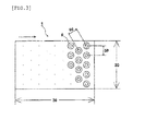
Fig. 3] Fig. 3 is a schematic view of an embodiment of the microchamber chip (1) for use in the present invention, said microchamber chip being viewed from directly above, and a pitch (50) indicates a distance between the centers of adj acent two microchambers (6). Each of dots in this figure represents the same microchamber as the microchamber (6). The direction indicated by the arrow of a dotted line is as described inFig. 1 . - [
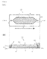
Fig. 4] Fig. 4 shows a schematic view 4(A) of a specific embodiment of the cell-spreading device of the present invention overlooked from directly above and a schematic view 4 (B) of a section taken on line A'-A' inFig. 4(A) . The direction indicated by the arrow of a dotted line is as described inFig. 1 . On the outlet (4), a reservoir (60) (volume is, for example, 500 µL) is arranged, and the cell suspension having been allowed to flow into through the inlet (3) is discharged from the outlet (4) and temporarily reserved in the reservoir (60). A ceiling and a side face of the channel-forming frame (2) are formed from a channel roof (2a) and a channel seal (2b), respectively. - [
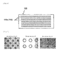
Fig. 5] Fig. 5 (A) shows an image of a microchamber chip surface given after the cell suspension is introduced into the channel of the cell-spreading device and allowed to stand still for 5 minutes in Example 1, andFig. 5(B) shows an image of a microchamber chip surface given after intermittent liquid sending in Example 1.Fig. 5(C) shows an arrangement pattern of recessed portions (110a) (retaining portions (110)) of a plate (100) of a chemical microdevice described in Japanese Patent Laid-Open Publication No.2004-212048 Fig. 5(D) shows an arrangement pattern of microchambers (6) of a microchamber chip (1) used in Example 1, and each of the arrows indicates a route and a direction in which the cells contained in the cell suspension move. InFigs. 5 (C) and 5(D) , only the recessed portions (110a) and the microchambers (6) are shown, respectively, but channels are formed on them, and an inlet and an outlet of each channel are present on an extension of a line connecting a tip and an end of the arrow. Therefore, the route and the direction, in which the cell suspension is introduced and is discharged, correspond to the route and the direction indicated by the arrow in each figure. - [
Fig. 6] Fig. 6 is a schematic plan view showing a state where a large number of fine recessed portions (110a) are formed as retaining portions (110) for retaining a sample, on a surface of a plate (100) of a chemical microdevice described in Japanese Patent Laid-Open Publication No.2004-212048 Fig. 1 of the publication; reference signs were altered). - [
Fig. 7] Fig. 7 isFig. 7 described inWO 2010/027003 (patent literature 1), and shows upper surface images of microarray chips A to C having microchambers different in inner diameter and depth, in said microchambers erythroid cells being enclosed. - The present invention will be described in detail hereinafter.
- As shown in, for example,
Fig. 1(A) , the "cell-spreading device" (10) of the present invention comprises at least a "microchamber chip" (1) having, on its surface, a "microchamber" (6) capable of enclosing and retaining a cell, a "channel-forming frame" (2) that is united with the microchamber chip (1) so that a "channel" (5) may be formed on the microchamber (6), an "inlet" (3) provided in the channel-forming frame (2) in order to allow a cell suspension to flow into the channel (5), and an "outlet" (4) provided in the channel-forming frame (2) in order to allow the cell suspension, which has been allowed to flow into the channel (5) through the inlet (3), to flow out from the channel (5), and
as shown inFig. 2 , when an aperture of the microchamber (6) is projected perpendicularly to a "longitudinal width (20) of the microchamber chip (1)", when an aperture of the microchamber (6) is projected perpendicularly to a longitudinal width (20) of the microchamber chip (1) (not a longitudinal width of the channel), the "void ratio" that is a ratio of the sum total of voids (40) to the longitudinal width (2) is not more than 5%, preferably 0%, said void (4) being a length of a portion where the projected aperture of the microchamber (6) is not present against the longitudinal width (20). - As shown in
Fig. 3 , the "longitudinal width (20) of the microchamber chip (1) " is defined as a width of the microchamber chip (1) in the short direction. On the other hand, the width of the microchamber chip (1) in the long direction is defined as a lateral width (30). In general, the direction in which the cell suspension flows in the channel (that is, direction of a straight line connecting the inlet (3) and the outlet (4)) is a long direction of the microchamber chip, and the longitudinal width (20) of the microchamber chip (1) is a width in the direction perpendicular thereto. - By the use of the cell-spreading device of the present invention, it is also possible to automate a series of steps of spreading the cell suspension onto the microchamber chip, enclosing and retaining cells in the microchamber, and staining and detecting specific rare cells.
- The microchamber chip (1) for use in the present invention has, on its surface, one or more microchambers (6) capable of enclosing and retaining one or more cells, and the void ratio is not more than 5%, preferably 0%.
- The microchamber in the present invention is an extremely fine concave hole (microwell) capable of "enclosing" and "retaining" one or more cells therein, and preferably has a bottom (that is, preferably not a through hole). Here, "enclosing" means that when a cell suspension is fed onto the surface of the cell-spreading microchamber chip, cells go into (are received in) the microchamber, and "retaining" means that the cells having been enclosed in the microchamber do not go out of the microchamber together with a stain solution, a washing liquid or the like having been fed to the surface of the cell-spreading microchamber chip.
- For example,
Fig. 5(C) shows an arrangement pattern of recessed portions (11a) (retaining portions (110)) of a hitherto used typical plate (plate of chemical microdevice described in Japanese Patent Laid-Open Publication No.2004-212048 - On the other hand, for example,
Fig. 5(D) shows a preferred arrangement pattern of the microchambers (6) in the present invention, and the void ratio of the microchamber chip having such an arrangement of the microchambers in the transverse direction of the channel is 0% when visually measured. In the case where the cells contained in the cell suspension move along routes indicated by the arrows inFig. 5(D) , the cells go on the microchambers (6) even on any route. Therefore, it can be seen that a possibility that the cells are enclosed in the microchambers (6) is extremely high. - As described above, it can be seen that when the cell suspension is spread on the microchamber chip of the cell-spreading device of the present invention, the ratio (recovery ratio of cells) of the total number of cells capable of being retained in the microchambers to the number of all of the cells contained in the cell suspension is extremely high.
- As shown in
Fig. 3 , the pitch (50) of the microchambers (6) is preferably not less than 1. 5 times the diameter of the microchamber (6). In theory, the pitch is preferably as equal to the diameter of the microchamber as possible (that is, the microchambers are preferably in contact with each other), but the microchamber chip (1) is mass-produced using a mold, and therefore, a minimum pitch making it possible to remove the chip from the mold is preferable. - The diameter of the microchamber (6) is preferably 20 to 150 µm. If the diameter of the microchamber exceeds 150 µm, cell retention power of the microchamber tends to be lowered. If the diameter of the microchamber is less than 20 µm, a cell is not enclosed in the microchamber in some cases.
- It is preferable to change the depth of the microchamber (6) depending upon the diameter of the microchamber (6), and by a person skilled in the art, the depth of the microchamber can be appropriately determined so that about 10 to 15 cells can be enclosed in one microchamber. Typically, the depth of the microchamber (6) is not less than 20 µm but not more than 100 µm.
- In
Figs. 1 to 3 , the shape of the microchamber (6) is an inverse conical shape having a flat bottom (vertical section shows a trapezoid), but the present invention is not limited to this embodiment, and for example, cylindrical shape, inverse hemispherical shape, inverse pyramid shape (inverse polygonal pyramid such as inverse quadrangular pyramid or inverse hexagonal pyramid), rectangular parallelepiped, etc. can be mentioned. Although the bottom of the microchamber is typically flat, it may have a curved surface. - As the material of the microchamber chip, the same material as that of a hitherto known microplate or the like can be used, and a material capable of being molded using a mold is preferable. Examples of such materials include polystyrene, polyethylene, polypropylene, polyamide, polycarbonate, polydimethylsiloxane [PDMS], polymethyl methacrylate [PMMA] and a cyclic olefin copolymer [COC]. The microchamber chip may be such a microchamber chip of combined plural materials as is obtained by laminating a substrate made of metal, glass, quartz glass or the like with a molded polymer.
- The production process for the microchamber chip (1) may be a process for producing the microchamber chip using a mold having a protruded portion corresponding to the shape of the microchamber (6) on the surface of a substrate, or may be a process for producing the microchamber chip by subjecting a substrate made of the above polymer, metal, glass or the like to direct processing (e.g., fine processing by lithography, drilling, LIGA processing). However, a process for producing the microchamber chip using a mold is preferable.
- The microchamber chip (1) may be subj ected to a surface treatment, when needed. Examples of the surface treatments include plasma treatment (oxygen plasma treatment or the like), corona discharge treatment and coating treatment with hydrophilic polymer, protein, lipid or the like, but the present invention is not limited to those treatments.
- As shown in, for example,
Fig. 1(A) , the channel (5) formed in the cell-spreading device (10) of the present invention has a bottom face that is a surface of the microchamber chip (1) and a side face and a ceiling which are formed by the channel-forming frame (2) that is provided so as to be united with the microchamber chip (1), and the channel serves to allow the cell suspension, which has been introduced through the inlet (3) provided in the channel-forming frame (2), to flow therein in the direction of the arrow of a dotted line. Thereafter, the cell suspension is allowed to flow out from the outlet (4) provided in the channel-forming frame (2). - As shown in, for example,
Fig. 1(B) , the channel (5) may have an embodiment wherein the bottom face is formed from a surface of the microchamber chip (1) and a member other than the microchamber chip (channel-forming frame (2) inFig. 1(B) ). In this case, however, in order to prevent loss of cells due to flow of the cell suspension in the region having no microchamber (1), it is desirable that in the short direction of the microchamber chip (1), the member other than the microchamber chip (1) does not form the bottom face. - Even after the microchamber chip (1) and the channel-forming frame (2) are united with each other, it is possible to separate them from each other. Moreover, it is also possible that after the channel is formed, only the ceiling (channel roof) is removed from the channel-forming frame (2) while remaining the side face only.
- The height (7) of the cannel (5), that is, a distance between the surface of the microchamber chip (1) other than the surface of the microchamber (6) and the ceiling (also referred to as a "height of ceiling" hereinafter) is preferably 50 to 500 µm. When the height of ceiling is in the above range, it is easy to move cells adhering to the surface of the microchamber chip (1) other than the surface of the microchamber (6) by the power of a water stream, and the time required for sedimentation of cells on the surface of the microchamber chip (1) can be shortened. Moreover, since clogging of the channel with cells, or the like rarely occurs, the cells are smoothly spread, so that such a height is preferable.
- The material of the channel-forming frame (2) is, for example, the same material as such a material of the microchamber chip (1) as described above, and it is preferable to use the same material as that of the microchamber chip (1). The channel-forming frame (2) may be subjected to the same surface treatment as such a surface treatment for the microchamber chip (1) as described above.
- As shown in, for example,
Fig. 4(B) , in the channel (5), a silicon sheet both surfaces of which have stickiness, namely, a channel seal (2b), is sandwiched between the channel roof (2a) and the microchamber chip (1), whereby the channel-forming frame (2) can be formed. - The cell suspension is, for example, blood such as human blood, lymph, tissue fluid, coelomic fluid or the like, which has a possibility of containing a rare cell, and it may be appropriately diluted with a diluting liquid or the like. The cell suspension is not limited to that of biological origin, and it may be a dispersion of cells, which is artificially prepared by suspending cells for the purpose of tests, researches, etc.
- The rare cell is, for example, a cancer cell. Particularly when the cell suspension is blood or a sample of blood origin, the rare cell may be CTC [circulating tumor cell or circulating cancer cell]. The diameters of various cells contained in such a cell suspension are each preferably 10 to 100 µm.
- According to, for example,
Fig. 1(A) , the method for detecting a rare cell of the present invention is a method wherein a rare cell having a possibility of being contained in a cell suspension is detected from the cell suspension by the use of the above-mentioned cell-spreading device (10), and the method comprises at least a step of introducing the cell suspension into the channel (5) through the inlet (3) of the cell-spreading device (10) to spread cells on the surface of the microchamber chip (1) and a step of enclosing the spread cells in the microchamber (6), and typically comprises the following steps. - Step (a): A physiological salt solution (preferably the same solvent as in the cell suspension used in the step (b)), such as PBS [phosphate buffered saline], is introduced through the inlet (3) of the cell-spreading device (10) to fill the channel (5) with it.
- Step (b): A cell suspension is introduced through the inlet (3) so that the physiological salt solution, with which the channel has been filledin the step (a), maybe replaced with the cell suspension, whereby the channel (5) is filled with the cell suspension. Simultaneously with introduction of the cell suspension through the inlet (3), the physiological salt solution is discharged from the outlet (4).
- Step (c): The cell suspension is allowed to stand still for 1 to 15 minutes (e.g., 5 minutes) to sediment cells contained in the cell suspension. At this time, some cells are enclosed in the mcrochambers (6), as shown in, for example,
Fig. 5(A) , but some cells adhere to the microchamber chip (1) surface other then the microchamber (6) surface. - Step (d) : When the sectional area of the channel is 1 to 1,000 mm2, the physiological salt solution (preferably the same solvent as that of the cell suspension used in the step (b)) having a volume that is about 1/100 to 1/2 (e.g., 1/50) of the volume of the cell suspension is sent through the inlet (3) at a flow rate of 1 to 1,000 µL/sec (flow rate per second is preferably adjusted so that the flow velocity may become 1 mm/sec or lower), and allowed to stand still for 1 to 30 seconds (e.g., 10 seconds). This step is preferably repeated twice or more, more preferably 10 times. In the case where liquid sending and standing still are repeated in this step, this liquid sending is particularly referred to as "intermittent liquid sending".
- As shown in
Fig. 5 (B) , by carrying out the intermittent liquid sending, the cells, which have not been enclosed in the microchambers (6) and have adhered to the surface other than the microchamber (6) surface, are apt to be enclosed in the microchambers (6). - Step (e) : A stain solution (e.g., solution of antibody labeled with fluorescent dye) capable of staining specific rare cells only is introduced through the inlet (3), allowed to react with cells under the specific conditions and thereafter discharged from the outlet (4). In order to wash the cells and the interior of the channel (5), a washing step wherein a washing liquid is introduced through the inlet (3) and discharged from the outlet (4) is preferably carried out once or more.
- Since the cells are retained in the microchambers (6), they are hardly discharged from the outlet (4) together with the stain solution or the washing liquid. On the other hand, the cells, which have not been retained in the microchambers (6) and have adhered to the microchamber chip surf ace other than the microchamber (6) surface, are liable to be discharged from the outlet (4) together with the stain solution or the washing liquid (this is referred to as "loss" (losing) of cells).
- Step (f): Stained rare cells are detected by microscopic observation or the like.
- The present invention is further described with reference to the following examples, but it should be construed that the present invention is in no way limited to those examples.
- A microchamber chip (made of polyethylene and produced using a given mold) having microchambers (6) arranged as shown in
Fig. 5(D) was used for a cell-spreading device. The microchambers of the microchamber chip each had a diameter of 100 µm, a depth of 50 µm and an inverse conical shape having a flat bottom. The pitch indicating a distance between the centers of the adjacent microchambers was 200 µm, and the void ratio was 0%. The longitudinal width and the lateral width of the microchamber chip were 25 mm and 70 mm, respectively, and the channel of the cell-spreading device had a height of 100 µm, a width of 15 mm and a length of 40 mm. That is to say, the sectional area of the channel of the cell-spreading device was 1.5 mm2, and the volume of the channel was 60 mm3 (= 0.06 mL). - In the first place, the channel of the cell-spreading device was filled with PBS containing 3% by weight of bovine serum albumin [BSA] (also referred to as "3% BSA-containing PBS" hereinafter). Next, 70 µL (about 7×10⁵ cells) of a cell suspension (cell concentration: 1×10⁷ cells/mL) in which 0.4% formaldehyde-fixed Jurkat cells had been dissolved in 3% BSA-containing PBS was introduced into the channel through the inlet under the flow rate conditions of 0.05 mL/min (= 50 µL/min) and allowed to stand still for 5 minutes, whereby most of PBS with which the channel had been filled was discharged from the outlet.
- An enlarged image of the surface of the microchamber chip at this time is shown in
Fig.5(A) . The cells were scattered and sedimented inside and outside the microchambers. Thereafter, intermittent liquid sending (after 1 µL of 3% BSA-containing PBS is sent at a flow velocity of 0.1 mL/min, it is allowed to stand still for 5 seconds) was carried out 10 times. - An enlarged image of the surface of the microchamber chip at this time is shown in
Fig. 5(B) . Most of the cells that had been scattered outside the microchambers before the intermittent liquid sending could be enclosed in the microchambers. When the number of all of the cells allowed to flow into the cell-spreading device is taken as 100%, the number of cells corresponding to 98% could be enclosed in the microchambers. That is to say, the recovery ratio of cells was 98%. - A recovery ratio of cells was determined in the same manner as in Example 1, except that the void ratio of the microchamber chip was changed to 1% or 5%. The intermittent liquid sending was further carried out another 10 times (total: 20 times), and a recovery ratio of cells was determined. The results are set forth in Table 1.
- A recovery ratio of cells was determined in the same manner as in Example 1, except that the void ratio of the microchamber chip was changed to 10%. The results are set forth in Table 1.
[Table 1] Void ratio Recovery ratio of cells (%) At the time of completion of 10 times of intermittent liquid sending At the time of completion of 20 times of intermittent liquid sending Ex. 2 1% 99% 98% 5% 94% 98% Comp. Ex. 1 10% 88% 89% - A recovery ratio of cells was determined in the same manner as in Example 1, except that a plate having a void ratio of 75%, which is shown in
Fig. 6 , was used. As a result, the recovery ratio of cells at the time of completion of 10 times of intermittent liquid sending was 26%. -
- 1:
- microchamber chip
- 2:
- channel-forming frame
- 2a:
- channel roof
- 2b:
- channel seal
- 3:
- inlet
- 4:
- outlet
- 5:
- channel
- 6:
- microchamber
- 7:
- height of channel (5)
- 10:
- cell-spreading device
- 20:
- longitudinal width of microchamber chip (1)
- 30:
- lateral width of microchamber chip (1) (long direction of microchamber chip (1))
- 40:
- void (length obtained by subtracting a width corresponding to a projected aperture of the microchamber (6) from a longitudinal width (2) in the case where an aperture of the microchamber (6) is projected perpendicularly to the longitudinal width (20) of the microchamber chip (1))
- 50:
- pitch
- 60:
- reservoir
- 100:
- plate
- 110:
- retaining portion
- 110a:
- recessed portion
Claims (7)
- A cell-spreading device (10) comprising at least:a microchamber chip (1) having, on its surface, a microchamber (6) capable of enclosing and retaining a cell,a channel-forming frame (2) that is united with the microchamber chip (1) so that a channel (5) may be formed on the microchamber (6),an inlet (3) provided in the channel-forming frame (2) in order to allow a cell suspension to flow into the channel (5), andan outlet (4) provided in the channel-forming frame (2) in order to allow the cell suspension, which has been allowed to flow into the channel (5) through the inlet (3), to flow out from the channel (5), whereinwhen an aperture of the microchamber (6) is projected perpendicularly to a longitudinal width (20) of the microchamber chip (1), the void ratio that is a ratio of the sum total of voids (40) to the longitudinal width (2) is not more than 5%, said void (40) being a length of a portion where the projected aperture of the microchamber (6) is not present against the longitudinal width (20).
- The cell-spreading device as claimed in claim 1, wherein the void ratio is 0%.
- The cell-spreading device as claimed in claim 1 or 2, wherein the pitch (50) of the microchamber (6) is not less than 1.5 times the diameter of the microchamber (6).
- The cell-spreading device as claimed in any one of claims 1 to 3, wherein the diameter of the microchamber (6) is not less than 20 µm but not more than 150 µm.
- The cell-spreading device as claimed in any one of claims 1 to 4, wherein the height (7) of the channel (5) is not less than 50 µm but not more than 500 µm.
- A method for detecting a rare cell having a possibility of being contained in a cell suspension, from the cell suspension by the use of the cell-spreading device (1) as claimed in any one of claims 1 to 5, said method comprising:a step of introducing the cell suspension into the channel (5) through the inlet (3) of the cell-spreading device (10) to spread cells on the surface of the microchamber chip (1), anda step of enclosing the spread cells in the microchamber (6).
- The method for detecting a rare cell as claimed in claim 6, wherein the diameter of the cell contained in the cell suspension is not less than 10 µm but not more than 100 µm.
Applications Claiming Priority (2)
| Application Number | Priority Date | Filing Date | Title |
|---|---|---|---|
| JP2012149405 | 2012-07-03 | ||
| PCT/JP2013/067978 WO2014007190A1 (en) | 2012-07-03 | 2013-07-01 | Cell-spreading device and method for detecting rare cell |
Publications (3)
| Publication Number | Publication Date |
|---|---|
| EP2871232A1 true EP2871232A1 (en) | 2015-05-13 |
| EP2871232A4 EP2871232A4 (en) | 2016-03-02 |
| EP2871232B1 EP2871232B1 (en) | 2021-05-05 |
Family
ID=49881946
Family Applications (1)
| Application Number | Title | Priority Date | Filing Date |
|---|---|---|---|
| EP13812976.2A Active EP2871232B1 (en) | 2012-07-03 | 2013-07-01 | Method for detecting rare cell |
Country Status (4)
| Country | Link |
|---|---|
| US (1) | US10584367B2 (en) |
| EP (1) | EP2871232B1 (en) |
| JP (1) | JP6218185B2 (en) |
| WO (1) | WO2014007190A1 (en) |
Families Citing this family (9)
| Publication number | Priority date | Publication date | Assignee | Title |
|---|---|---|---|---|
| WO2015034011A1 (en) * | 2013-09-04 | 2015-03-12 | 独立行政法人産業技術総合研究所 | Microarray chip and cell analysis method using same |
| JP6528378B2 (en) * | 2014-09-19 | 2019-06-12 | コニカミノルタ株式会社 | Cell expansion method and kit therefor |
| JP6583602B2 (en) * | 2014-09-19 | 2019-10-02 | コニカミノルタ株式会社 | Method for analyzing intracellular nucleic acid, and system and kit therefor |
| WO2016121574A1 (en) * | 2015-01-29 | 2016-08-04 | コニカミノルタ株式会社 | Method for simultaneous detection of blood cells having interacting molecules |
| JPWO2016140327A1 (en) * | 2015-03-04 | 2017-12-14 | 国立研究開発法人産業技術総合研究所 | Micro chamber array plate |
| KR102713290B1 (en) * | 2015-09-29 | 2024-10-04 | 도쿄 오카 고교 가부시키가이샤 | Substrate, structure, method for producing structure, method for selecting cells, method for producing cells, and method for producing secretion |
| WO2017141789A1 (en) * | 2016-02-19 | 2017-08-24 | コニカミノルタ株式会社 | Method for storing blood-derived specimens and method for determining rare cells |
| JP6958547B2 (en) | 2016-04-27 | 2021-11-02 | 凸版印刷株式会社 | Reaction vessel and biochemical analysis method |
| EP4155712A1 (en) * | 2021-09-28 | 2023-03-29 | Siemens Healthcare Diagnostics, Inc. | Device and method for optically analyzing blood cells |
Family Cites Families (13)
| Publication number | Priority date | Publication date | Assignee | Title |
|---|---|---|---|---|
| EP2332651A3 (en) | 2001-10-25 | 2011-08-31 | Bar Ilan University | Interactive transparent individual cells biochip processor |
| EP2107120A1 (en) * | 2002-07-24 | 2009-10-07 | Board of Regents, The University of Texas System | Capture and detection of microbes by membrane methods |
| JP2004212048A (en) | 2002-11-14 | 2004-07-29 | Starlite Co Ltd | Chemical microdevice |
| JP2004330038A (en) | 2003-05-06 | 2004-11-25 | Starlite Co Ltd | Chemical micro device |
| GB0321158D0 (en) | 2003-09-10 | 2003-10-08 | Central Research Lab Ltd | Apparatus and method for handling cells,embryos or oocytes |
| JP4679197B2 (en) | 2005-03-25 | 2011-04-27 | 株式会社東芝 | Microbial separator |
| US7695956B2 (en) | 2006-01-12 | 2010-04-13 | Biocept, Inc. | Device for cell separation and analysis and method of using |
| EP2336348B1 (en) | 2008-09-02 | 2014-11-05 | National Institute of Advanced Industrial Science And Technology | Cell detection method, and microarray chip for use in the method |
| US20120129208A1 (en) * | 2009-03-18 | 2012-05-24 | Michelle Khine | Honeycomb shrink wells for stem cell culture |
| US8551425B2 (en) * | 2009-05-20 | 2013-10-08 | California Institute Of Technology | Method for cancer detection, diagnosis and prognosis |
| GB0909923D0 (en) * | 2009-06-09 | 2009-07-22 | Oxford Gene Tech Ip Ltd | Picowell capture devices for analysing single cells or other particles |
| JP5704590B2 (en) * | 2010-02-05 | 2015-04-22 | 国立大学法人東京農工大学 | Detection of circulating tumor cells using size-selective microcavity array |
| US8941062B2 (en) | 2010-11-16 | 2015-01-27 | 1087 Systems, Inc. | System for identifying and sorting living cells |
-
2013
- 2013-07-01 JP JP2014523725A patent/JP6218185B2/en not_active Expired - Fee Related
- 2013-07-01 US US14/411,191 patent/US10584367B2/en not_active Expired - Fee Related
- 2013-07-01 EP EP13812976.2A patent/EP2871232B1/en active Active
- 2013-07-01 WO PCT/JP2013/067978 patent/WO2014007190A1/en not_active Ceased
Also Published As
| Publication number | Publication date |
|---|---|
| EP2871232A4 (en) | 2016-03-02 |
| WO2014007190A1 (en) | 2014-01-09 |
| US20150337355A1 (en) | 2015-11-26 |
| JP6218185B2 (en) | 2017-10-25 |
| EP2871232B1 (en) | 2021-05-05 |
| JPWO2014007190A1 (en) | 2016-06-02 |
| US10584367B2 (en) | 2020-03-10 |
Similar Documents
| Publication | Publication Date | Title |
|---|---|---|
| EP2871232B1 (en) | Method for detecting rare cell | |
| US20210370298A1 (en) | Microfluidic Device For Cell Separation And Uses Thereof | |
| US10018632B2 (en) | Microfluidic devices for the capture of biological sample components | |
| Qi et al. | Probing single cells using flow in microfluidic devices | |
| US20100018584A1 (en) | Microfluidic system and method for manufacturing the same | |
| US20180299425A1 (en) | Methods and Apparatus for Segregation of Particles | |
| WO2009051734A1 (en) | Microchip-based devices for capturing circulating tumor cells and methods of their use | |
| EP2910642B1 (en) | Method for recovering rare cells and method for detecting rare cells | |
| MX2012006244A (en) | Methods and apparatus for segregation of particles, including segregation and proliferation of fetal and stem cells. | |
| EP3684507B1 (en) | Particle sorting in a microfluidic system | |
| JPWO2016121574A1 (en) | Method for simultaneous detection of blood cells having interacting molecules | |
| US20110014619A1 (en) | Reaction treatment apparatus and reaction treatment method | |
| WO2011028483A2 (en) | Methods and apparatus for segregation of particles, including additional sources of sample collection for separation of nucleated fetal cells | |
| KR20240105284A (en) | Apparatus for separating particles from urine and method for thereof | |
| KR20240105288A (en) | Method for isolation and pretreatment for axosomes from saliva | |
| WO2013024817A1 (en) | Two-dimensional cell spreading device and cell spreading method using same | |
| Esmaeilsabzali | Development of a microfluidic platform for size-based enrichment and immunomagnetic isolation of circulating tumour cells | |
| HK40034368A (en) | Particle sorting in a microfluidic system | |
| HK1079960B (en) | Microfluidic device for cell separation and uses thereof |
Legal Events
| Date | Code | Title | Description |
|---|---|---|---|
| PUAI | Public reference made under article 153(3) epc to a published international application that has entered the european phase |
Free format text: ORIGINAL CODE: 0009012 |
|
| 17P | Request for examination filed |
Effective date: 20150122 |
|
| AK | Designated contracting states |
Kind code of ref document: A1 Designated state(s): AL AT BE BG CH CY CZ DE DK EE ES FI FR GB GR HR HU IE IS IT LI LT LU LV MC MK MT NL NO PL PT RO RS SE SI SK SM TR |
|
| AX | Request for extension of the european patent |
Extension state: BA ME |
|
| DAX | Request for extension of the european patent (deleted) | ||
| RA4 | Supplementary search report drawn up and despatched (corrected) |
Effective date: 20160202 |
|
| RIC1 | Information provided on ipc code assigned before grant |
Ipc: C12M 1/34 20060101AFI20160127BHEP Ipc: C12M 1/00 20060101ALI20160127BHEP Ipc: G01N 33/48 20060101ALI20160127BHEP Ipc: G01N 35/02 20060101ALI20160127BHEP Ipc: C12Q 1/02 20060101ALI20160127BHEP |
|
| STAA | Information on the status of an ep patent application or granted ep patent |
Free format text: STATUS: EXAMINATION IS IN PROGRESS |
|
| 17Q | First examination report despatched |
Effective date: 20170803 |
|
| RAP1 | Party data changed (applicant data changed or rights of an application transferred) |
Owner name: KONICA MINOLTA, INC. |
|
| GRAP | Despatch of communication of intention to grant a patent |
Free format text: ORIGINAL CODE: EPIDOSNIGR1 |
|
| STAA | Information on the status of an ep patent application or granted ep patent |
Free format text: STATUS: GRANT OF PATENT IS INTENDED |
|
| INTG | Intention to grant announced |
Effective date: 20200819 |
|
| GRAS | Grant fee paid |
Free format text: ORIGINAL CODE: EPIDOSNIGR3 |
|
| GRAJ | Information related to disapproval of communication of intention to grant by the applicant or resumption of examination proceedings by the epo deleted |
Free format text: ORIGINAL CODE: EPIDOSDIGR1 |
|
| GRAL | Information related to payment of fee for publishing/printing deleted |
Free format text: ORIGINAL CODE: EPIDOSDIGR3 |
|
| STAA | Information on the status of an ep patent application or granted ep patent |
Free format text: STATUS: EXAMINATION IS IN PROGRESS |
|
| INTC | Intention to grant announced (deleted) | ||
| GRAP | Despatch of communication of intention to grant a patent |
Free format text: ORIGINAL CODE: EPIDOSNIGR1 |
|
| STAA | Information on the status of an ep patent application or granted ep patent |
Free format text: STATUS: GRANT OF PATENT IS INTENDED |
|
| INTG | Intention to grant announced |
Effective date: 20210302 |
|
| RIN1 | Information on inventor provided before grant (corrected) |
Inventor name: YAMAMURA, SHOHEI Inventor name: HOSHI, KUMIKO Inventor name: KATAOKA, MASATOSHI Inventor name: YATSUSHIRO, SHOUKI Inventor name: ARAKI, JUNGO |
|
| GRAA | (expected) grant |
Free format text: ORIGINAL CODE: 0009210 |
|
| STAA | Information on the status of an ep patent application or granted ep patent |
Free format text: STATUS: THE PATENT HAS BEEN GRANTED |
|
| AK | Designated contracting states |
Kind code of ref document: B1 Designated state(s): AL AT BE BG CH CY CZ DE DK EE ES FI FR GB GR HR HU IE IS IT LI LT LU LV MC MK MT NL NO PL PT RO RS SE SI SK SM TR |
|
| REG | Reference to a national code |
Ref country code: GB Ref legal event code: FG4D |
|
| REG | Reference to a national code |
Ref country code: CH Ref legal event code: EP |
|
| REG | Reference to a national code |
Ref country code: AT Ref legal event code: REF Ref document number: 1389853 Country of ref document: AT Kind code of ref document: T Effective date: 20210515 |
|
| REG | Reference to a national code |
Ref country code: DE Ref legal event code: R096 Ref document number: 602013077356 Country of ref document: DE |
|
| REG | Reference to a national code |
Ref country code: IE Ref legal event code: FG4D |
|
| REG | Reference to a national code |
Ref country code: LT Ref legal event code: MG9D |
|
| REG | Reference to a national code |
Ref country code: AT Ref legal event code: MK05 Ref document number: 1389853 Country of ref document: AT Kind code of ref document: T Effective date: 20210505 |
|
| PG25 | Lapsed in a contracting state [announced via postgrant information from national office to epo] |
Ref country code: LT Free format text: LAPSE BECAUSE OF FAILURE TO SUBMIT A TRANSLATION OF THE DESCRIPTION OR TO PAY THE FEE WITHIN THE PRESCRIBED TIME-LIMIT Effective date: 20210505 Ref country code: FI Free format text: LAPSE BECAUSE OF FAILURE TO SUBMIT A TRANSLATION OF THE DESCRIPTION OR TO PAY THE FEE WITHIN THE PRESCRIBED TIME-LIMIT Effective date: 20210505 Ref country code: AT Free format text: LAPSE BECAUSE OF FAILURE TO SUBMIT A TRANSLATION OF THE DESCRIPTION OR TO PAY THE FEE WITHIN THE PRESCRIBED TIME-LIMIT Effective date: 20210505 Ref country code: BG Free format text: LAPSE BECAUSE OF FAILURE TO SUBMIT A TRANSLATION OF THE DESCRIPTION OR TO PAY THE FEE WITHIN THE PRESCRIBED TIME-LIMIT Effective date: 20210805 Ref country code: HR Free format text: LAPSE BECAUSE OF FAILURE TO SUBMIT A TRANSLATION OF THE DESCRIPTION OR TO PAY THE FEE WITHIN THE PRESCRIBED TIME-LIMIT Effective date: 20210505 |
|
| PG25 | Lapsed in a contracting state [announced via postgrant information from national office to epo] |
Ref country code: LV Free format text: LAPSE BECAUSE OF FAILURE TO SUBMIT A TRANSLATION OF THE DESCRIPTION OR TO PAY THE FEE WITHIN THE PRESCRIBED TIME-LIMIT Effective date: 20210505 Ref country code: IS Free format text: LAPSE BECAUSE OF FAILURE TO SUBMIT A TRANSLATION OF THE DESCRIPTION OR TO PAY THE FEE WITHIN THE PRESCRIBED TIME-LIMIT Effective date: 20210905 Ref country code: GR Free format text: LAPSE BECAUSE OF FAILURE TO SUBMIT A TRANSLATION OF THE DESCRIPTION OR TO PAY THE FEE WITHIN THE PRESCRIBED TIME-LIMIT Effective date: 20210806 Ref country code: ES Free format text: LAPSE BECAUSE OF FAILURE TO SUBMIT A TRANSLATION OF THE DESCRIPTION OR TO PAY THE FEE WITHIN THE PRESCRIBED TIME-LIMIT Effective date: 20210505 Ref country code: PL Free format text: LAPSE BECAUSE OF FAILURE TO SUBMIT A TRANSLATION OF THE DESCRIPTION OR TO PAY THE FEE WITHIN THE PRESCRIBED TIME-LIMIT Effective date: 20210505 Ref country code: PT Free format text: LAPSE BECAUSE OF FAILURE TO SUBMIT A TRANSLATION OF THE DESCRIPTION OR TO PAY THE FEE WITHIN THE PRESCRIBED TIME-LIMIT Effective date: 20210906 Ref country code: NO Free format text: LAPSE BECAUSE OF FAILURE TO SUBMIT A TRANSLATION OF THE DESCRIPTION OR TO PAY THE FEE WITHIN THE PRESCRIBED TIME-LIMIT Effective date: 20210805 Ref country code: SE Free format text: LAPSE BECAUSE OF FAILURE TO SUBMIT A TRANSLATION OF THE DESCRIPTION OR TO PAY THE FEE WITHIN THE PRESCRIBED TIME-LIMIT Effective date: 20210505 Ref country code: RS Free format text: LAPSE BECAUSE OF FAILURE TO SUBMIT A TRANSLATION OF THE DESCRIPTION OR TO PAY THE FEE WITHIN THE PRESCRIBED TIME-LIMIT Effective date: 20210505 |
|
| REG | Reference to a national code |
Ref country code: NL Ref legal event code: MP Effective date: 20210505 |
|
| PG25 | Lapsed in a contracting state [announced via postgrant information from national office to epo] |
Ref country code: NL Free format text: LAPSE BECAUSE OF FAILURE TO SUBMIT A TRANSLATION OF THE DESCRIPTION OR TO PAY THE FEE WITHIN THE PRESCRIBED TIME-LIMIT Effective date: 20210505 |
|
| PG25 | Lapsed in a contracting state [announced via postgrant information from national office to epo] |
Ref country code: EE Free format text: LAPSE BECAUSE OF FAILURE TO SUBMIT A TRANSLATION OF THE DESCRIPTION OR TO PAY THE FEE WITHIN THE PRESCRIBED TIME-LIMIT Effective date: 20210505 Ref country code: CZ Free format text: LAPSE BECAUSE OF FAILURE TO SUBMIT A TRANSLATION OF THE DESCRIPTION OR TO PAY THE FEE WITHIN THE PRESCRIBED TIME-LIMIT Effective date: 20210505 Ref country code: DK Free format text: LAPSE BECAUSE OF FAILURE TO SUBMIT A TRANSLATION OF THE DESCRIPTION OR TO PAY THE FEE WITHIN THE PRESCRIBED TIME-LIMIT Effective date: 20210505 Ref country code: SK Free format text: LAPSE BECAUSE OF FAILURE TO SUBMIT A TRANSLATION OF THE DESCRIPTION OR TO PAY THE FEE WITHIN THE PRESCRIBED TIME-LIMIT Effective date: 20210505 Ref country code: SM Free format text: LAPSE BECAUSE OF FAILURE TO SUBMIT A TRANSLATION OF THE DESCRIPTION OR TO PAY THE FEE WITHIN THE PRESCRIBED TIME-LIMIT Effective date: 20210505 Ref country code: RO Free format text: LAPSE BECAUSE OF FAILURE TO SUBMIT A TRANSLATION OF THE DESCRIPTION OR TO PAY THE FEE WITHIN THE PRESCRIBED TIME-LIMIT Effective date: 20210505 |
|
| REG | Reference to a national code |
Ref country code: DE Ref legal event code: R097 Ref document number: 602013077356 Country of ref document: DE |
|
| REG | Reference to a national code |
Ref country code: CH Ref legal event code: PL |
|
| PLBE | No opposition filed within time limit |
Free format text: ORIGINAL CODE: 0009261 |
|
| STAA | Information on the status of an ep patent application or granted ep patent |
Free format text: STATUS: NO OPPOSITION FILED WITHIN TIME LIMIT |
|
| PG25 | Lapsed in a contracting state [announced via postgrant information from national office to epo] |
Ref country code: MC Free format text: LAPSE BECAUSE OF FAILURE TO SUBMIT A TRANSLATION OF THE DESCRIPTION OR TO PAY THE FEE WITHIN THE PRESCRIBED TIME-LIMIT Effective date: 20210505 |
|
| REG | Reference to a national code |
Ref country code: BE Ref legal event code: MM Effective date: 20210731 |
|
| 26N | No opposition filed |
Effective date: 20220208 |
|
| PG25 | Lapsed in a contracting state [announced via postgrant information from national office to epo] |
Ref country code: LI Free format text: LAPSE BECAUSE OF NON-PAYMENT OF DUE FEES Effective date: 20210731 Ref country code: CH Free format text: LAPSE BECAUSE OF NON-PAYMENT OF DUE FEES Effective date: 20210731 |
|
| PG25 | Lapsed in a contracting state [announced via postgrant information from national office to epo] |
Ref country code: IS Free format text: LAPSE BECAUSE OF FAILURE TO SUBMIT A TRANSLATION OF THE DESCRIPTION OR TO PAY THE FEE WITHIN THE PRESCRIBED TIME-LIMIT Effective date: 20210905 Ref country code: LU Free format text: LAPSE BECAUSE OF NON-PAYMENT OF DUE FEES Effective date: 20210701 Ref country code: AL Free format text: LAPSE BECAUSE OF FAILURE TO SUBMIT A TRANSLATION OF THE DESCRIPTION OR TO PAY THE FEE WITHIN THE PRESCRIBED TIME-LIMIT Effective date: 20210505 |
|
| PG25 | Lapsed in a contracting state [announced via postgrant information from national office to epo] |
Ref country code: IT Free format text: LAPSE BECAUSE OF FAILURE TO SUBMIT A TRANSLATION OF THE DESCRIPTION OR TO PAY THE FEE WITHIN THE PRESCRIBED TIME-LIMIT Effective date: 20210505 Ref country code: IE Free format text: LAPSE BECAUSE OF NON-PAYMENT OF DUE FEES Effective date: 20210701 Ref country code: BE Free format text: LAPSE BECAUSE OF NON-PAYMENT OF DUE FEES Effective date: 20210731 |
|
| PGFP | Annual fee paid to national office [announced via postgrant information from national office to epo] |
Ref country code: GB Payment date: 20220606 Year of fee payment: 10 |
|
| PGFP | Annual fee paid to national office [announced via postgrant information from national office to epo] |
Ref country code: FR Payment date: 20220609 Year of fee payment: 10 |
|
| PGFP | Annual fee paid to national office [announced via postgrant information from national office to epo] |
Ref country code: DE Payment date: 20220531 Year of fee payment: 10 |
|
| PG25 | Lapsed in a contracting state [announced via postgrant information from national office to epo] |
Ref country code: HU Free format text: LAPSE BECAUSE OF FAILURE TO SUBMIT A TRANSLATION OF THE DESCRIPTION OR TO PAY THE FEE WITHIN THE PRESCRIBED TIME-LIMIT; INVALID AB INITIO Effective date: 20130701 |
|
| P01 | Opt-out of the competence of the unified patent court (upc) registered |
Effective date: 20230510 |
|
| PG25 | Lapsed in a contracting state [announced via postgrant information from national office to epo] |
Ref country code: CY Free format text: LAPSE BECAUSE OF FAILURE TO SUBMIT A TRANSLATION OF THE DESCRIPTION OR TO PAY THE FEE WITHIN THE PRESCRIBED TIME-LIMIT Effective date: 20210505 |
|
| REG | Reference to a national code |
Ref country code: DE Ref legal event code: R119 Ref document number: 602013077356 Country of ref document: DE |
|
| GBPC | Gb: european patent ceased through non-payment of renewal fee |
Effective date: 20230701 |
|
| PG25 | Lapsed in a contracting state [announced via postgrant information from national office to epo] |
Ref country code: MK Free format text: LAPSE BECAUSE OF FAILURE TO SUBMIT A TRANSLATION OF THE DESCRIPTION OR TO PAY THE FEE WITHIN THE PRESCRIBED TIME-LIMIT Effective date: 20210505 Ref country code: DE Free format text: LAPSE BECAUSE OF NON-PAYMENT OF DUE FEES Effective date: 20240201 Ref country code: GB Free format text: LAPSE BECAUSE OF NON-PAYMENT OF DUE FEES Effective date: 20230701 |
|
| PG25 | Lapsed in a contracting state [announced via postgrant information from national office to epo] |
Ref country code: FR Free format text: LAPSE BECAUSE OF NON-PAYMENT OF DUE FEES Effective date: 20230731 |
|
| PG25 | Lapsed in a contracting state [announced via postgrant information from national office to epo] |
Ref country code: TR Free format text: LAPSE BECAUSE OF FAILURE TO SUBMIT A TRANSLATION OF THE DESCRIPTION OR TO PAY THE FEE WITHIN THE PRESCRIBED TIME-LIMIT Effective date: 20210505 |
|
| PG25 | Lapsed in a contracting state [announced via postgrant information from national office to epo] |
Ref country code: MT Free format text: LAPSE BECAUSE OF FAILURE TO SUBMIT A TRANSLATION OF THE DESCRIPTION OR TO PAY THE FEE WITHIN THE PRESCRIBED TIME-LIMIT Effective date: 20210505 |