EP2871131A1 - Variable geometry helicopter engine inlet - Google Patents
Variable geometry helicopter engine inlet Download PDFInfo
- Publication number
- EP2871131A1 EP2871131A1 EP20140191067 EP14191067A EP2871131A1 EP 2871131 A1 EP2871131 A1 EP 2871131A1 EP 20140191067 EP20140191067 EP 20140191067 EP 14191067 A EP14191067 A EP 14191067A EP 2871131 A1 EP2871131 A1 EP 2871131A1
- Authority
- EP
- European Patent Office
- Prior art keywords
- inlet
- variable area
- engine
- engine inlet
- variable
- Prior art date
- Legal status (The legal status is an assumption and is not a legal conclusion. Google has not performed a legal analysis and makes no representation as to the accuracy of the status listed.)
- Granted
Links
Images




Classifications
-
- B—PERFORMING OPERATIONS; TRANSPORTING
- B64—AIRCRAFT; AVIATION; COSMONAUTICS
- B64D—EQUIPMENT FOR FITTING IN OR TO AIRCRAFT; FLIGHT SUITS; PARACHUTES; ARRANGEMENT OR MOUNTING OF POWER PLANTS OR PROPULSION TRANSMISSIONS IN AIRCRAFT
- B64D33/00—Arrangement in aircraft of power plant parts or auxiliaries not otherwise provided for
- B64D33/02—Arrangement in aircraft of power plant parts or auxiliaries not otherwise provided for of combustion air intakes
-
- F—MECHANICAL ENGINEERING; LIGHTING; HEATING; WEAPONS; BLASTING
- F02—COMBUSTION ENGINES; HOT-GAS OR COMBUSTION-PRODUCT ENGINE PLANTS
- F02C—GAS-TURBINE PLANTS; AIR INTAKES FOR JET-PROPULSION PLANTS; CONTROLLING FUEL SUPPLY IN AIR-BREATHING JET-PROPULSION PLANTS
- F02C7/00—Features, components parts, details or accessories, not provided for in, or of interest apart form groups F02C1/00 - F02C6/00; Air intakes for jet-propulsion plants
- F02C7/04—Air intakes for gas-turbine plants or jet-propulsion plants
- F02C7/042—Air intakes for gas-turbine plants or jet-propulsion plants having variable geometry
-
- B—PERFORMING OPERATIONS; TRANSPORTING
- B64—AIRCRAFT; AVIATION; COSMONAUTICS
- B64D—EQUIPMENT FOR FITTING IN OR TO AIRCRAFT; FLIGHT SUITS; PARACHUTES; ARRANGEMENT OR MOUNTING OF POWER PLANTS OR PROPULSION TRANSMISSIONS IN AIRCRAFT
- B64D33/00—Arrangement in aircraft of power plant parts or auxiliaries not otherwise provided for
- B64D33/02—Arrangement in aircraft of power plant parts or auxiliaries not otherwise provided for of combustion air intakes
- B64D2033/0253—Arrangement in aircraft of power plant parts or auxiliaries not otherwise provided for of combustion air intakes specially adapted for particular type of aircraft
-
- Y—GENERAL TAGGING OF NEW TECHNOLOGICAL DEVELOPMENTS; GENERAL TAGGING OF CROSS-SECTIONAL TECHNOLOGIES SPANNING OVER SEVERAL SECTIONS OF THE IPC; TECHNICAL SUBJECTS COVERED BY FORMER USPC CROSS-REFERENCE ART COLLECTIONS [XRACs] AND DIGESTS
- Y10—TECHNICAL SUBJECTS COVERED BY FORMER USPC
- Y10T—TECHNICAL SUBJECTS COVERED BY FORMER US CLASSIFICATION
- Y10T137/00—Fluid handling
- Y10T137/0536—Highspeed fluid intake means [e.g., jet engine intake]
Definitions
- the subject matter disclosed herein relates to a helicopter engine inlet and, more particularly, to a helicopter engine inlet with variable geometry.
- a problem with high speed rotorcraft is the need to balance external aerodynamic performance with engine inlet performance.
- Larger inlet capture areas are required for higher engine performance at lower speeds and especially hover conditions to permit a greater amount of air to flow into the engine than would be possible at low speeds or hover conditions with relatively small inlets.
- These larger inlet capture areas do not provide appreciable engine performance benefit at higher speeds and in many cases act to the detriment of the overall aerodynamic performance of the aircraft.
- the larger inlet capture areas tend to be oversized in the presence of ramming air at high speeds and thus may result in inlet spillage. Such spillage, when coupled with the larger exposed surface facing into the freestream flow, may result in higher drag.
- a variable area engine inlet of a helicopter includes first inlet portions disposed to face one another in opposite directions and at a distance from one another and second inlet portions extending between the first inlet portions and being disposed to face one another in opposite directions and at a distance from one another.
- the first and second inlet portions define a capture area and at least one or both of the first and second inlet portions include a movable portion disposed to occupy and move between first and second positions.
- the first position is associated with a non-constricted condition of the capture area and the second position is associated with a constricted condition of the capture area.
- Particular embodiments may include any of the following optional features, alone or in combination:
- Leading sides of the first and second inlet portions may comprise aerodynamic elements.
- the movable portion may be movable into the first position in accordance with low-speed or hover flight conditions and into the second position in accordance with high-speed flight conditions.
- a helicopter includes an airframe including a variable area engine inlet, at least one rotor, which is rotatable relative to the airframe to generate lift and/or thrust and an engine disposed within an interior of the airframe to be receptive of air drawn into the interior through the variable area engine inlet.
- the engine is coupled to the at least one rotor to drive rotation of the rotor in accordance with a combustion of a mixture of fuel and the air.
- a capture area of the variable area engine inlet is variable in accordance with current conditions.
- Particular embodiments may include any of the following optional features, alone or in combination:
- the first inlet portions may be oriented perpendicularly with respect to the second inlet portions.
- Leading sides of the first and second inlet portions may comprise aerodynamic elements.
- At least one of the first or second inlet portions may comprise a movable portion disposed to occupy and move between first and second positions, the first position being associated with a non-constricted condition of the variable area engine inlet, and the second position being associated with a constricted condition of the variable area engine inlet.
- the helicopter further may comprise a controller configured to constrict a capture area of the variable area engine inlet in accordance with high-speed flight conditions and to dilate the capture area in accordance with low-speed or hover flight conditions.
- variable area engine inlet may comprise first and second variable area engine inlets and the controller may be configured to independently vary respective capture areas of the first and second variable area engine inlets in accordance with the current conditions and asymmetric flows relative to the first and second variable area engine inlets.
- a method of controlling a variable area engine inlet of a helicopter includes determining whether a current flight condition is a hover or low-speed flight condition or a high-speed flight condition, constricting a capture area of the variable area engine inlet in an event a result of the determining indicates that the current flight condition is the high-speed flight condition and dilating the capture area in an event the result of the determining indicates that the current flight condition is the hover or low-speed flight condition.
- Particular embodiments may include any of the following optional features, alone or in combination:
- a single- or multiple-duct variable geometry helicopter engine inlet includes a movable portion of the inlet such that a size of a capture area of the inlet can be varied.
- the movable portion includes an internal flow surface and an aerodynamic surface for external flow to limit drag while the internal flow surface varies the inlet capture area and diffusion or convergence ratios.
- the capture area of the inlet can thus be varied to suit a current flight condition.
- the movable portion can be provided on a top and/or a side of the inlet and may provide for an increased diffusion ratio in its constricted area position where such increased diffusion ratio may be tolerated or desired at higher speeds due to the presence of ram effects.
- a helicopter 10 is provided and includes an airframe 11.
- the airframe 11 is formed to define a cabin portion 12 and a tail portion 13.
- the airframe includes a main rotor section 14 and a variable area engine inlet 15 (or "inlets” in the case of a multiple-duct engine inlet).
- the airframe includes a tail rotor section 16.
- the helicopter 10 further includes at least a main rotor 140 rotatably supported in the main rotor section 14 and a tail rotor 160 rotatably supported in the tail rotor section 16. Both the main rotor 140 and the tail rotor 160 are rotatable relative to the airframe 11 to generate lift forces and thrust forces.
- the helicopter 10 also includes an engine 17 and a controller 18.
- the engine 17 is disposed within an interior of the airframe 11 and is receptive of air drawn into the interior of the airframe 11 through the variable area engine inlet 15.
- the engine 17 is coupled to the main rotor 140 and the tail rotor 160 and is configured to drive rotation of the main rotor 140 and the tail rotor 160 by way of gear trains in accordance with combustion of a mixture of fuel and the air drawn into the interior of the airframe 11.
- the controller 18 may be embodied as a flight control computer.
- the controller 18 may include a memory unit 180, a processing unit 181 and servo elements 182, which are coupled to the variable area engine inlet 15.
- the memory unit 180 has executable instructions stored thereon. When executed, the executable instructions cause the processing unit 181 to determine whether a current flight condition is a hover, low-speed or high-speed flight condition or whether there is an asymmetric condition in a multi-duct inlet and to operate the servo elements 182 to vary a capture area 150 of the variable area engine inlet 15 in accordance with the determined current condition.
- the controller 18 is configured to constrict the capture area 150 of the variable area engine inlet 15 in accordance with the current flight condition being a high-speed flight condition, to dilate the capture area 150 in accordance with the current flight condition being a low-speed or a hover flight condition and to use a combination of constricted and unconstructed areas in multi-duct inlets to equalize flow conditions.
- the variable area engine inlet 15 includes a pair of first inlet portions 20 and a pair of second inlet portions 21.
- the first inlet portions 20 are disposed to face one another in opposite directions and at a distance from one another.
- the second inlet portions 21 respectively extend between the first inlet portions 20 and are disposed to face one another in opposite directions and at a distance from one another.
- the first inlet portions 20 may be oriented transversely or, in some cases, perpendicularly with respect to the second inlet portions 21.
- one of the first inlet portions 20 may be provided as a section 201 of fuselage of the airframe 11 while the other of the first inlet portions 20 may be provided as a horizontally oriented top wall section 202.
- one of the second inlet portions 21 may be provided as a section 203 of a main rotor pylon while the other of the second inlet sections 21 may be provided as a vertically oriented side wall section 204.
- leading sides of the first and second inlet portions 20 and 21 may include aerodynamic elements 22 to limit drag on airflow flowing around the variable area engine inlet 15.
- a distance between the section 201 of the fuselage of the airframe 11 and the horizontally oriented top wall section 202 defines at least an initial height H1 of the variable area engine inlet 15 and a distance between the section 203 of the main rotor pylon and the vertically oriented side wall section 204 defines at least an initial width W1 of the variable area engine inlet 15.
- the initial height H1 and the initial width W1 may cooperatively define a non-constricted or dilated condition of the capture area 150.
- first inlet portions 20 and/or the second inlet portions 21 may include a movable portion 23.
- the movable portion 23 is disposed to occupy and move between first and second positions. The first position is associated with a non-constricted condition of the capture area 150 of the variable area engine inlet 15 and the second position is associated with a constricted condition of the capture area 150.
- the movable portion 23 may be provided as the horizontally oriented top wall section 202 or may be a component of the same.
- the non-constricted condition is assumed when the current flight conditions are low-speed or hover flight conditions and the movable portion 23 is accordingly disposed such that a height of the variable area engine inlet 15 is defined as the initial height H1.
- the constricted condition is assumed when the current flight conditions are high-speed flight conditions and the movable portion 23 is accordingly disposed such that the height of the variable area engine inlet 15 is defined as a secondary height H2, which is shorter than the initial height H1 due to the fact that the horizontally oriented top wall section 202 has moved downwardly.
- the movable portion 23 may be provided as the vertically oriented side wall section 204 or may be a component of the same.
- the non-constricted condition is assumed when the current flight conditions are low-speed or hover flight conditions and the movable portion 23 is accordingly disposed such that a width of the variable area engine inlet 15 is defined as the initial width W1.
- the constricted condition is assumed when the current flight conditions are high-speed flight conditions and the movable portion 23 is accordingly disposed such that the width of the variable area engine inlet 15 is defined as a secondary width W2, which is shorter than the initial width W1 due to the fact that the vertically oriented side wall section 204 has moved laterally.
- the airframe 11 may include a hinge 230 by which the movable portion 23 is coupled to the airframe 11.
- the movable portion 23 is disposed to occupy and move between the first and second positions by being driven to pivot about the hinge 230 by the servo elements 182 of the controller 18, which in some embodiments may be provided as a solenoid motor disposed proximate to the movable portion 23. It should be understood that other embodiments exist for driving, moving or otherwise controlling the movable portion 23 to move between the first and second positions.
- These other embodiments may include, but are not limited to, moving the movable portion 23 in a translating motion in which the movable portion 23 does not pivot about any predefined axis or providing the movable portion 23 with smart materials and changing the shape of the movable portion 23 by heating or electrifying the smart materials.
- variable area engine inlet 15 may be provided as a first (or starboard side) variable area engine inlet 151 and a second (or port side) variable area engine inlet 152.
- both the first and second variable area engine inlets 151 and 152 provide air flow to the engine 17 and may be controlled as described above by the controller 18.
- the controller 18 may be configured to independently vary respective capture areas 150 of the first and second variable area engine inlets 151 and 152 in accordance with the current conditions by driving movements of the movable portion 23 in each of the first and second variable area engine inlets 151 and 152.
- the controller 18 may dilate the slower moving interior (relative to the yaw movement) one of the first and second variable area engine inlets 151 and 152 and constrict the faster moving outer (relative to the yaw movement) one of the first and second variable area engine inlets 151 and 152.
- a method of controlling a variable area engine inlet of a helicopter includes determining whether a current flight condition is a hover, low-speed or high speed flight condition (operation 30), constricting a capture area of the variable area engine inlet in an event a result of the determining indicates that the current flight condition is the high-speed flight condition (operation 31) and dilating the capture area in an event the result of the determining indicates that the current flight condition is the hover or low-speed flight condition (operation 32).
- the dilating may include moving a horizontally and/or vertically oriented inlet portion of the variable area engine inlet to a first position associated with a non-constricted condition of the capture area and the constricting may include moving the horizontally and/or vertically oriented inlet portion to a second position associated with a constricted condition of the capture area.
- the method may further include an independent varying of respective capture areas of a multiple-duct engine inlet in accordance with the current conditions and in response to a condition characterized by asymmetric flows relative to the first and second variable area engine inlets 151 and 152 (operation 310).
- the description provided above generally relates to cases in which the movable portion 23 is driven to move by the servo elements 182 of the controller 18, alternative embodiments exist in which movement of the movable portion 23 is not controlled by the controller 18 or any component thereof and is, instead, at least partially passively responsive to current flight conditions.
- the movable portion 23 may be passively moved from the first position to the second position as a speed of the helicopter 10 increases in response to corresponding increases in air flow pressures and/or speeds within the variable area engine inlet 15. That is, the movement of the movable portion 23 may be driven by the increases in air flow pressures and/or speeds within the variable area engine inlet 15.
- the movable portion 23 may be coupled to the airframe 11 by way of the hinge 230 and an elastic element 231.
- the elastic element 231 is disposed to bias the movable portion 23 towards the first position but is configured to permit the movable portion 23 to move toward the second position in passive response to air pressures 232 increasing beyond a predefined limit.
- the movable portion 23 may be provided as a section 201 of fuselage of the airframe 11 or may be a component of the same.
- the non-constricted condition is assumed when the current flight conditions are low-speed or hover flight conditions and the movable portion 23 is accordingly disposed such that a height of the variable area engine inlet 15 is defined as the initial height H11.
- the constricted condition is assumed when the current flight conditions are high-speed flight conditions and the movable portion 23 is accordingly disposed such that the height of the variable area engine inlet 15 is defined as a secondary height H22, which is shorter than the initial height H11 due to the fact that the section 201 of the fuselage has moved upwardly.
- the movement of the section 201 of the fuselage may open an alternate inlet 153.
- This alternate inlet 153 may provide for airflow to be used in compartment cooling, transmission bay cooling, etc.
- the alternate inlet 153 may also be used to pull off low energy boundary layer flow and to prevent the boundary layer flow from being ingested by the engine inlet to thereby increase engine performance.
- variable area engine inlet 15 described above presents little to no performance compromise in accommodating hover or low- versus high-speed flight conditions. Indeed, analyses of the above-described structures have shown significant performance increases in hover with negligible performance differences during high-speed flight conditions.
Landscapes
- Engineering & Computer Science (AREA)
- Chemical & Material Sciences (AREA)
- Combustion & Propulsion (AREA)
- Aviation & Aerospace Engineering (AREA)
- Physics & Mathematics (AREA)
- Geometry (AREA)
- Mechanical Engineering (AREA)
- General Engineering & Computer Science (AREA)
- Toys (AREA)
Abstract
Description
- The subject matter disclosed herein relates to a helicopter engine inlet and, more particularly, to a helicopter engine inlet with variable geometry.
- A problem with high speed rotorcraft is the need to balance external aerodynamic performance with engine inlet performance. Larger inlet capture areas are required for higher engine performance at lower speeds and especially hover conditions to permit a greater amount of air to flow into the engine than would be possible at low speeds or hover conditions with relatively small inlets. These larger inlet capture areas, however, do not provide appreciable engine performance benefit at higher speeds and in many cases act to the detriment of the overall aerodynamic performance of the aircraft. Moreover, the larger inlet capture areas tend to be oversized in the presence of ramming air at high speeds and thus may result in inlet spillage. Such spillage, when coupled with the larger exposed surface facing into the freestream flow, may result in higher drag.
- Prior solutions for sizing rotorcraft inlets have required that a fixed inlet size be chosen. The fixed inlet size necessitates a performance compromise in either engine performance at lower speeds and hover, greater aircraft drag at higher speeds or a combination of the two if a design is chosen in the middle range of inlet sizes.
- Other prior solutions have given rise to variable geometry inlets but these have generally been used only for supersonic fixed wing aircraft and, most often to mitigate supersonic shock.
- According to one aspect of the invention, a variable area engine inlet of a helicopter is provided and includes first inlet portions disposed to face one another in opposite directions and at a distance from one another and second inlet portions extending between the first inlet portions and being disposed to face one another in opposite directions and at a distance from one another. The first and second inlet portions define a capture area and at least one or both of the first and second inlet portions include a movable portion disposed to occupy and move between first and second positions. The first position is associated with a non-constricted condition of the capture area and the second position is associated with a constricted condition of the capture area.
- Particular embodiments may include any of the following optional features, alone or in combination:
- The first inlet portions may be oriented perpendicularly with respect to the second inlet portions.
- Leading sides of the first and second inlet portions may comprise aerodynamic elements.
- The movable portion may be movable into the first position in accordance with low-speed or hover flight conditions and into the second position in accordance with high-speed flight conditions.
- According to another aspect of the invention, a helicopter is provided and includes an airframe including a variable area engine inlet, at least one rotor, which is rotatable relative to the airframe to generate lift and/or thrust and an engine disposed within an interior of the airframe to be receptive of air drawn into the interior through the variable area engine inlet. The engine is coupled to the at least one rotor to drive rotation of the rotor in accordance with a combustion of a mixture of fuel and the air. A capture area of the variable area engine inlet is variable in accordance with current conditions.
- Particular embodiments may include any of the following optional features, alone or in combination:
- The variable area engine inlet may be disposed at an upper portion of the airframe.
- The variable area engine inlet may comprise: First inlet portions disposed to face one another in opposite directions and at a distance from one another; and second inlet portions extending between the first inlet portions and being disposed to face one another in opposite directions and at a distance from one another.
- The first inlet portions may be oriented perpendicularly with respect to the second inlet portions.
- Leading sides of the first and second inlet portions may comprise aerodynamic elements.
- At least one of the first or second inlet portions may comprise a movable portion disposed to occupy and move between first and second positions, the first position being associated with a non-constricted condition of the variable area engine inlet, and the second position being associated with a constricted condition of the variable area engine inlet.
- The helicopter further may comprise a controller configured to constrict a capture area of the variable area engine inlet in accordance with high-speed flight conditions and to dilate the capture area in accordance with low-speed or hover flight conditions.
- The variable area engine inlet may comprise first and second variable area engine inlets and the controller may be configured to independently vary respective capture areas of the first and second variable area engine inlets in accordance with the current conditions and asymmetric flows relative to the first and second variable area engine inlets.
- The airframe may include an alternate engine inlet that is configured to open when the capture area of the variable area engine inlet is constricted.
- According to yet another aspect of the invention, a method of controlling a variable area engine inlet of a helicopter is provided and includes determining whether a current flight condition is a hover or low-speed flight condition or a high-speed flight condition, constricting a capture area of the variable area engine inlet in an event a result of the determining indicates that the current flight condition is the high-speed flight condition and dilating the capture area in an event the result of the determining indicates that the current flight condition is the hover or low-speed flight condition.
- Particular embodiments may include any of the following optional features, alone or in combination:
- The variable engine inlet may comprise first and second variable area engine inlets and the method further may comprise independently varying respective capture areas of the first and second variable area engine inlets in response to asymmetric flow conditions relative to the first and second variable area engine inlets.
- These and other advantages and features will become more apparent from the following description taken in conjunction with the drawings.
- The subject matter, which is regarded as the invention, is particularly pointed out and distinctly claimed in the claims at the conclusion of the specification. The foregoing and other features, and advantages of the invention are apparent from the following detailed description taken in conjunction with the accompanying drawings in which:
-
FIG. 1 is a schematic illustration of a helicopter in accordance with embodiments; -
FIG. 2 is a schematic illustration of a controller of the helicopter ofFIG. 1 ; -
FIG. 3 is a perspective view of helicopter engine inlets in accordance with embodiments; -
FIG. 4 is an axial view of a helicopter engine inlet with variable geometry in accordance with embodiments; -
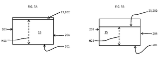
FIG. 5A is a schematic axial view of the helicopter engine inlet ofFIG. 4 in a non-constricted condition; -
FIG. 5B is a schematic axial view of the helicopter engine inlet ofFIG. 4 in a constricted condition; -
FIG. 6 is an axial view of a helicopter engine inlet with variable geometry in accordance with embodiments; -
FIG. 7A is a schematic axial view of the helicopter engine inlet ofFIG. 6 in a non-constricted condition; -
FIG. 7B is a schematic axial view of the helicopter engine inlet ofFIG. 6 in a constricted condition; -
FIG. 8 is a schematic illustration of a moveable portion of the helicopter inlets ofFIGS. 4 and5A ,5B orFIGS. 6 and7A, 7B with a hinge element in accordance with embodiments; -
FIG. 9 is a flow diagram illustrating a method of controlling the helicopter inlets ofFIGS. 4-7B in accordance with embodiments; -
FIG. 10 is a schematic illustration of a passive movable portion of the helicopter inlets ofFIGS. 4 and5A ,5B orFIGS. 7 and 7A,7B in accordance with embodiments; -
FIG. 11A is a schematic axial view of the helicopter engine inlet in a non-constricted condition in accordance with further embodiments; and -
FIG. 11B is a schematic axial view of the helicopter engine inlet in a constricted condition such that an alternative inlet is opened in accordance with further embodiments. - The detailed description explains embodiments of the invention, together with advantages and features, by way of example with reference to the drawings.
- As will be described below, a single- or multiple-duct variable geometry helicopter engine inlet is provided and includes a movable portion of the inlet such that a size of a capture area of the inlet can be varied. The movable portion includes an internal flow surface and an aerodynamic surface for external flow to limit drag while the internal flow surface varies the inlet capture area and diffusion or convergence ratios. The capture area of the inlet can thus be varied to suit a current flight condition. The movable portion can be provided on a top and/or a side of the inlet and may provide for an increased diffusion ratio in its constricted area position where such increased diffusion ratio may be tolerated or desired at higher speeds due to the presence of ram effects.
- With reference to
FIGS. 1-3 , ahelicopter 10 is provided and includes anairframe 11. Theairframe 11 is formed to define acabin portion 12 and atail portion 13. At a top or uppermost section of thecabin portion 12, the airframe includes amain rotor section 14 and a variable area engine inlet 15 (or "inlets" in the case of a multiple-duct engine inlet). At thetail portion 13, the airframe includes atail rotor section 16. Thehelicopter 10 further includes at least amain rotor 140 rotatably supported in themain rotor section 14 and atail rotor 160 rotatably supported in thetail rotor section 16. Both themain rotor 140 and thetail rotor 160 are rotatable relative to theairframe 11 to generate lift forces and thrust forces. - The
helicopter 10 also includes anengine 17 and acontroller 18. Theengine 17 is disposed within an interior of theairframe 11 and is receptive of air drawn into the interior of theairframe 11 through the variablearea engine inlet 15. Theengine 17 is coupled to themain rotor 140 and thetail rotor 160 and is configured to drive rotation of themain rotor 140 and thetail rotor 160 by way of gear trains in accordance with combustion of a mixture of fuel and the air drawn into the interior of theairframe 11. Thecontroller 18 may be embodied as a flight control computer. - In accordance with embodiments, the
controller 18 may include amemory unit 180, aprocessing unit 181 andservo elements 182, which are coupled to the variablearea engine inlet 15. Thememory unit 180 has executable instructions stored thereon. When executed, the executable instructions cause theprocessing unit 181 to determine whether a current flight condition is a hover, low-speed or high-speed flight condition or whether there is an asymmetric condition in a multi-duct inlet and to operate theservo elements 182 to vary acapture area 150 of the variablearea engine inlet 15 in accordance with the determined current condition. That is, thecontroller 18 is configured to constrict thecapture area 150 of the variablearea engine inlet 15 in accordance with the current flight condition being a high-speed flight condition, to dilate thecapture area 150 in accordance with the current flight condition being a low-speed or a hover flight condition and to use a combination of constricted and unconstructed areas in multi-duct inlets to equalize flow conditions. - The variable
area engine inlet 15 includes a pair of first inlet portions 20 and a pair ofsecond inlet portions 21. The first inlet portions 20 are disposed to face one another in opposite directions and at a distance from one another. Thesecond inlet portions 21 respectively extend between the first inlet portions 20 and are disposed to face one another in opposite directions and at a distance from one another. The first inlet portions 20 may be oriented transversely or, in some cases, perpendicularly with respect to thesecond inlet portions 21. - In accordance with embodiments and, as shown in
FIG. 3 , one of the first inlet portions 20 may be provided as asection 201 of fuselage of theairframe 11 while the other of the first inlet portions 20 may be provided as a horizontally orientedtop wall section 202. In these embodiments, one of thesecond inlet portions 21 may be provided as asection 203 of a main rotor pylon while the other of thesecond inlet sections 21 may be provided as a vertically orientedside wall section 204. In accordance with further embodiments, leading sides of the first andsecond inlet portions 20 and 21 may includeaerodynamic elements 22 to limit drag on airflow flowing around the variablearea engine inlet 15. - As shown in
FIG. 3 (and inFIGS. 4 and6 to be described below), a distance between thesection 201 of the fuselage of theairframe 11 and the horizontally orientedtop wall section 202 defines at least an initial height H1 of the variablearea engine inlet 15 and a distance between thesection 203 of the main rotor pylon and the vertically orientedside wall section 204 defines at least an initial width W1 of the variablearea engine inlet 15. The initial height H1 and the initial width W1 may cooperatively define a non-constricted or dilated condition of thecapture area 150. - With reference to
FIGS. 4-7B , at least one or both of the first inlet portions 20 and/or thesecond inlet portions 21 may include amovable portion 23. Themovable portion 23 is disposed to occupy and move between first and second positions. The first position is associated with a non-constricted condition of thecapture area 150 of the variablearea engine inlet 15 and the second position is associated with a constricted condition of thecapture area 150. - That is, as shown in
FIGS. 4 ,5A and 5B , themovable portion 23 may be provided as the horizontally orientedtop wall section 202 or may be a component of the same. In such cases, the non-constricted condition is assumed when the current flight conditions are low-speed or hover flight conditions and themovable portion 23 is accordingly disposed such that a height of the variablearea engine inlet 15 is defined as the initial height H1. By contrast, the constricted condition is assumed when the current flight conditions are high-speed flight conditions and themovable portion 23 is accordingly disposed such that the height of the variablearea engine inlet 15 is defined as a secondary height H2, which is shorter than the initial height H1 due to the fact that the horizontally orientedtop wall section 202 has moved downwardly. - Similarly, as shown in
FIGS. 6 ,7A and 7B , themovable portion 23 may be provided as the vertically orientedside wall section 204 or may be a component of the same. In such cases, the non-constricted condition is assumed when the current flight conditions are low-speed or hover flight conditions and themovable portion 23 is accordingly disposed such that a width of the variablearea engine inlet 15 is defined as the initial width W1. By contrast, the constricted condition is assumed when the current flight conditions are high-speed flight conditions and themovable portion 23 is accordingly disposed such that the width of the variablearea engine inlet 15 is defined as a secondary width W2, which is shorter than the initial width W1 due to the fact that the vertically orientedside wall section 204 has moved laterally. - In accordance with embodiments and, with reference to
FIG. 8 , theairframe 11 may include ahinge 230 by which themovable portion 23 is coupled to theairframe 11. In such cases, themovable portion 23 is disposed to occupy and move between the first and second positions by being driven to pivot about thehinge 230 by theservo elements 182 of thecontroller 18, which in some embodiments may be provided as a solenoid motor disposed proximate to themovable portion 23. It should be understood that other embodiments exist for driving, moving or otherwise controlling themovable portion 23 to move between the first and second positions. These other embodiments may include, but are not limited to, moving themovable portion 23 in a translating motion in which themovable portion 23 does not pivot about any predefined axis or providing themovable portion 23 with smart materials and changing the shape of themovable portion 23 by heating or electrifying the smart materials. - With reference back to
FIGS. 1, 2 and3 , it is seen that the variablearea engine inlet 15 may be provided as a first (or starboard side) variablearea engine inlet 151 and a second (or port side) variablearea engine inlet 152. In such cases, both the first and second variablearea engine inlets engine 17 and may be controlled as described above by thecontroller 18. In particular, thecontroller 18 may be configured to independently varyrespective capture areas 150 of the first and second variablearea engine inlets movable portion 23 in each of the first and second variablearea engine inlets helicopter 10 where flow asymmetries may result in distortions at the face of theengine 17, thecontroller 18 may dilate the slower moving interior (relative to the yaw movement) one of the first and second variablearea engine inlets area engine inlets - In accordance with further aspects of the invention and, with reference to
FIG. 9 , a method of controlling a variable area engine inlet of a helicopter is provided. The method includes determining whether a current flight condition is a hover, low-speed or high speed flight condition (operation 30), constricting a capture area of the variable area engine inlet in an event a result of the determining indicates that the current flight condition is the high-speed flight condition (operation 31) and dilating the capture area in an event the result of the determining indicates that the current flight condition is the hover or low-speed flight condition (operation 32). As noted above, the dilating may include moving a horizontally and/or vertically oriented inlet portion of the variable area engine inlet to a first position associated with a non-constricted condition of the capture area and the constricting may include moving the horizontally and/or vertically oriented inlet portion to a second position associated with a constricted condition of the capture area. - As shown in
FIG. 9 , the method may further include an independent varying of respective capture areas of a multiple-duct engine inlet in accordance with the current conditions and in response to a condition characterized by asymmetric flows relative to the first and second variablearea engine inlets 151 and 152 (operation 310). - In accordance with still further aspects of the invention and, with reference to
FIG. 10 , it will be understood that although the description provided above generally relates to cases in which themovable portion 23 is driven to move by theservo elements 182 of thecontroller 18, alternative embodiments exist in which movement of themovable portion 23 is not controlled by thecontroller 18 or any component thereof and is, instead, at least partially passively responsive to current flight conditions. For example, themovable portion 23 may be passively moved from the first position to the second position as a speed of thehelicopter 10 increases in response to corresponding increases in air flow pressures and/or speeds within the variablearea engine inlet 15. That is, the movement of themovable portion 23 may be driven by the increases in air flow pressures and/or speeds within the variablearea engine inlet 15. In such cases, as shown inFIG. 10 , themovable portion 23 may be coupled to theairframe 11 by way of thehinge 230 and anelastic element 231. Theelastic element 231 is disposed to bias themovable portion 23 towards the first position but is configured to permit themovable portion 23 to move toward the second position in passive response toair pressures 232 increasing beyond a predefined limit. - In accordance with further embodiments and, as shown in
FIGS. 11A and 11B , themovable portion 23 may be provided as asection 201 of fuselage of theairframe 11 or may be a component of the same. In such cases, the non-constricted condition is assumed when the current flight conditions are low-speed or hover flight conditions and themovable portion 23 is accordingly disposed such that a height of the variablearea engine inlet 15 is defined as the initial height H11. By contrast, the constricted condition is assumed when the current flight conditions are high-speed flight conditions and themovable portion 23 is accordingly disposed such that the height of the variablearea engine inlet 15 is defined as a secondary height H22, which is shorter than the initial height H11 due to the fact that thesection 201 of the fuselage has moved upwardly. In such cases, the movement of thesection 201 of the fuselage may open analternate inlet 153. Thisalternate inlet 153 may provide for airflow to be used in compartment cooling, transmission bay cooling, etc. Thealternate inlet 153 may also be used to pull off low energy boundary layer flow and to prevent the boundary layer flow from being ingested by the engine inlet to thereby increase engine performance. - The variable
area engine inlet 15 described above presents little to no performance compromise in accommodating hover or low- versus high-speed flight conditions. Indeed, analyses of the above-described structures have shown significant performance increases in hover with negligible performance differences during high-speed flight conditions. - While the invention has been described in detail in connection with only a limited number of embodiments, it should be readily understood that the invention is not limited to such disclosed embodiments. Rather, the invention can be modified to incorporate any number of variations, alterations, substitutions or equivalent arrangements not heretofore described, but which are commensurate with the spirit and scope of the invention. Additionally, while various embodiments of the invention have been described, it is to be understood that aspects of the invention may include only some of the described embodiments. Accordingly, the invention is not to be seen as limited by the foregoing description, but is only limited by the scope of the appended claims.
Claims (15)
- A variable area engine inlet (15) of a helicopter (10), comprising:first inlet portions (20) disposed to face one another in opposite directions and at a distance from one another; andsecond inlet portions (21) extending between the first inlet portions and being disposed to face one another in opposite directions and at a distance from one another,the first and second inlet portions (20, 21) defining a capture area (150) and at least one or both of the first and second inlet portions (20, 21) comprising a movable portion (23) disposed to occupy and move between first and second positions,the first position being associated with a non-constricted condition of the capture area (150), andthe second position being associated with a constricted condition of the capture area (150).
- The variable area engine (15) inlet according to claim 1, wherein the first inlet portions (20) are oriented perpendicularly with respect to the second inlet portions (21).
- The variable area engine inlet (15) according to claim 1 or 2, wherein leading sides of the first and second inlet portions (20, 21) comprise aerodynamic elements (22).
- The variable area engine inlet (15) according to any of claims 1 to 3, wherein the movable portion (23) is movable into the first position in accordance with low-speed or hover flight conditions and into the second position in accordance with high-speed flight conditions.
- A helicopter (10), comprising:an airframe (11) including a variable area engine inlet (15) according to any of the previous claims;at least one rotor (140), which is rotatable relative to the airframe (11) to generate lift and/or thrust; andan engine (17) disposed within an interior of the airframe (11) to be receptive of air drawn into the interior through the variable area engine inlet (15), the engine (17) being coupled to the at least one rotor (140) to drive rotation of the rotor in accordance with a combustion of a mixture of fuel and the air,a capture area (150) of the variable area engine inlet (15) being variable in accordance with current conditions.
- The helicopter (10) according to claim 5, wherein the variable area engine inlet (15) is disposed at an upper portion of the airframe (11).
- The helicopter (10) according to claim 5 or 6, further comprising a controller (18) configured to constrict the capture area (150) of the variable area engine inlet (15) in accordance with high-speed flight conditions and to dilate the capture area (150) in accordance with low-speed or hover flight conditions.
- The helicopter (10) according to claim 7, wherein the variable area engine inlet (15) comprises first and second variable area engine inlets and the controller (18) is configured to independently vary respective capture areas of the first and second variable area engine inlets in accordance with the current conditions and asymmetric flows relative to the first and second variable area engine inlets.
- The helicopter (10) according to any of claims 5 to 8, wherein the airframe (11) includes an alternate engine inlet that is configured to open when the capture area (150) of the variable area engine inlet (15) is constricted.
- A variable area engine inlet (15) of a helicopter (10), being configured to vary a capture area (150) of the variable area engine inlet (15) in accordance with current conditions.
- The variable area engine inlet (15) according to claim 10, further comprising:first inlet portions (20) disposed to face one another in opposite directions and at a distance from one another; andsecond inlet portions (21) extending between the first inlet portions (20) and being disposed to face one another in opposite directions and at a distance from one another.
- The variable area engine inlet (15) according to claim 10 or 11, wherein at least one of the first or second inlet portions (20, 21) comprises a movable portion disposed to occupy and move between first and second positions,
the first position being associated with a non-constricted condition of the variable area engine inlet (15), and
the second position being associated with a constricted condition of the variable area engine inlet (15);
the variable area engine inlet (15) particularly including any of the features recited in claims 2 to 4. - A helicopter (10), comprising:an airframe (11) including a variable area engine inlet (15) according to any of claims 10 to 12;at least one rotor (140), which is rotatable relative to the airframe (11) to generate lift and/or thrust; andan engine (17) disposed within an interior of the airframe (11) to be receptive of air drawn into the interior through the variable area engine inlet (15), the engine (17) being coupled to the at least one rotor (140) to drive rotation of the rotor (140) in accordance with a combustion of a mixture of fuel and the air,a capture area (150) of the variable area engine inlet (15) being variable in accordance with current conditions;the helicopter particularly including any of the features recited in claims 6 to 9.
- A method of controlling a variable area engine inlet (15) of a helicopter (10), the method comprising:determining whether a current flight condition is a hover or low-speed flight condition or a high-speed flight condition;constricting a capture area (150) of the variable area engine inlet (15) in an event a result of the determining indicates that the current flight condition is the high-speed flight condition; anddilating the capture area (150) in an event the result of the determining indicates that the current flight condition is the hover or low-speed flight condition.
- The method according to claim 14, wherein the variable engine inlet (15) comprises first and second variable area engine inlets and the method further comprises independently varying respective capture areas of the first and second variable area engine inlets in response to asymmetric flow conditions relative to the first and second variable area engine inlets.
Applications Claiming Priority (1)
| Application Number | Priority Date | Filing Date | Title |
|---|---|---|---|
| US14/074,265 US9656760B2 (en) | 2013-11-07 | 2013-11-07 | Variable geometry helicopter engine inlet |
Publications (2)
| Publication Number | Publication Date |
|---|---|
| EP2871131A1 true EP2871131A1 (en) | 2015-05-13 |
| EP2871131B1 EP2871131B1 (en) | 2018-12-05 |
Family
ID=51866002
Family Applications (1)
| Application Number | Title | Priority Date | Filing Date |
|---|---|---|---|
| EP14191067.9A Not-in-force EP2871131B1 (en) | 2013-11-07 | 2014-10-30 | Variable geometry helicopter engine inlet |
Country Status (2)
| Country | Link |
|---|---|
| US (2) | US9656760B2 (en) |
| EP (1) | EP2871131B1 (en) |
Cited By (2)
| Publication number | Priority date | Publication date | Assignee | Title |
|---|---|---|---|---|
| EP3406527A1 (en) * | 2017-05-24 | 2018-11-28 | Sikorsky Aircraft Corporation | Variable geometry engine inlet for high speed aircraft |
| EP3733524A1 (en) | 2019-04-30 | 2020-11-04 | Airbus Helicopters | Rotorcraft provided with an aerodynamic device comprising a fairing having an air intake |
Families Citing this family (5)
| Publication number | Priority date | Publication date | Assignee | Title |
|---|---|---|---|---|
| FR3065757B1 (en) * | 2017-04-27 | 2019-04-26 | Airbus Helicopters | AIRCRAFT HAVING A STATIC AIR INTAKE SYSTEM WITH A SEPARATOR AND ANTI-VIBRATION PROCESS |
| US20190276158A1 (en) * | 2018-03-08 | 2019-09-12 | Bell Helicopter Textron Inc. | Active cooling system |
| US12208909B2 (en) * | 2019-09-08 | 2025-01-28 | Textron Innovations Inc. | Aircraft with bifurcated air inlet |
| JP2024508177A (en) * | 2021-03-05 | 2024-02-22 | リリウム ゲーエムベーハー | Aircraft engine with variable area exhaust nozzle |
| CN113323756B (en) * | 2021-06-22 | 2022-08-16 | 西安航天动力研究所 | Double-flow-passage graded adjustable wide-range air inlet passage, engine and air inlet adjusting method |
Citations (7)
| Publication number | Priority date | Publication date | Assignee | Title |
|---|---|---|---|---|
| US3338049A (en) * | 1966-02-01 | 1967-08-29 | Gen Electric | Gas turbine engine including separator for removing extraneous matter |
| US3449891A (en) * | 1966-11-15 | 1969-06-17 | United Aircraft Corp | Engine inlet air particle separator |
| US4304094A (en) * | 1979-11-16 | 1981-12-08 | United Technologies Corp. | Engine air particle separator for use with gas turbine engine |
| EP0515746A1 (en) * | 1991-05-22 | 1992-12-02 | Mitsubishi Jukogyo Kabushiki Kaisha | Gas turbine and operating method of the same |
| JPH07277291A (en) * | 1994-04-13 | 1995-10-24 | Mitsubishi Heavy Ind Ltd | Helicopter air intake device |
| US20070025838A1 (en) * | 2005-07-29 | 2007-02-01 | Aerospace Filtration Systems, Inc. | Control of engine intake door |
| FR2906569A1 (en) * | 2006-09-28 | 2008-04-04 | Eurocopter France | Polyvalent air inlet for turboshaft engine of e.g. helicopter, has movable closing unit for closing non filtering air inlets when aircraft is at proximity of ground and filtering air inlets during flying of aircraft |
Family Cites Families (52)
| Publication number | Priority date | Publication date | Assignee | Title |
|---|---|---|---|---|
| US3265331A (en) * | 1964-09-18 | 1966-08-09 | Gen Electric | Supersonic inlet |
| US3664612A (en) * | 1969-12-22 | 1972-05-23 | Boeing Co | Aircraft engine variable highlight inlet |
| US3575259A (en) * | 1970-04-10 | 1971-04-20 | Boeing Co | Retractable noise suppression system |
| DE2511468C3 (en) * | 1975-03-15 | 1980-11-13 | Vereinigte Flugtechnische Werke- Fokker Gmbh, 2800 Bremen | Engine intake with an auxiliary intake flap |
| US4012013A (en) * | 1976-02-05 | 1977-03-15 | The Boeing Company | Variable camber inlet for supersonic aircraft |
| US4372505A (en) * | 1979-12-17 | 1983-02-08 | The Boeing Company | Supersonic inlet having variable area sideplate openings |
| US4307743A (en) * | 1980-10-01 | 1981-12-29 | The Boeing Company | Device to start an overcontracted mixed compression supersonic inlet |
| US4474344A (en) * | 1981-03-25 | 1984-10-02 | The Boeing Company | Compression-sealed nacelle inlet door assembly |
| GB2140090B (en) * | 1982-12-23 | 1986-10-01 | Rolls Royce | Air intakes of helicopter mounted gas turbine engines |
| DE3407137A1 (en) * | 1984-02-28 | 1985-08-29 | Messerschmitt-Bölkow-Blohm GmbH, 8012 Ottobrunn | DEVICE FOR IMPROVING THE FLOW RATIO AT THE AIR INLET FOR GAS TURBINE ENGINES BUILT IN PLANES |
| DE3811614C1 (en) * | 1988-04-07 | 1989-05-18 | Messerschmitt-Boelkow-Blohm Gmbh, 8012 Ottobrunn, De | |
| US4979699A (en) * | 1989-05-26 | 1990-12-25 | Grumman Aerospace Corporation | Flight control augmentation inlet device |
| DE4008956A1 (en) * | 1990-03-20 | 1991-09-26 | Messerschmitt Boelkow Blohm | INLET SYSTEM FOR SUPERVISOR OR HYPERSONIC AIRCRAFT |
| US5226455A (en) * | 1990-12-17 | 1993-07-13 | Dupont Anthony A | Variable geometry duct seal |
| US5216878A (en) * | 1991-06-28 | 1993-06-08 | The Boeing Company | Mixed exhaust flow supersonic jet engine and method |
| US5697394A (en) * | 1993-03-02 | 1997-12-16 | United Technologies Corporation | Low observable engine air inlet system |
| US5967394A (en) | 1994-11-04 | 1999-10-19 | Roll Systems, Inc. | Method and apparatus for pinless feeding of web to a utilization device |
| FR2745606B1 (en) * | 1996-03-01 | 1998-04-30 | Aerospatiale | STATOREACTOR WITH EVOLUTIVE GEOMETRY FOR AIRCRAFT |
| US5894987A (en) * | 1996-08-26 | 1999-04-20 | The United States Of America As Represented By The Secretary Of The Air Force | Variable area inlet for vehicle thermal control |
| US5794432A (en) * | 1996-08-27 | 1998-08-18 | Diversitech, Inc. | Variable pressure and variable air flow turbofan engines |
| DE19651491C2 (en) * | 1996-12-11 | 1999-04-01 | Daimler Benz Aerospace Ag | Air intake for engines |
| US6089505A (en) * | 1997-07-22 | 2000-07-18 | Mcdonnell Douglas Corporation | Mission adaptive inlet |
| US6349899B1 (en) * | 2000-04-04 | 2002-02-26 | The Boeing Company | Aircraft auxiliary air intake with ram and flush opening door |
| US6910327B2 (en) * | 2003-07-28 | 2005-06-28 | The Boeing Company | Apparatus and methods for varying inlet lip geometry of a jet engine inlet |
| US7192462B2 (en) * | 2004-04-14 | 2007-03-20 | Aerospace Filtration Systems, Inc. | Engine air filter and sealing system |
| US7587899B2 (en) | 2004-08-27 | 2009-09-15 | University Of Houston | Shape memory alloy actuated adaptive exhaust nozzle for jet engine |
| US7491253B2 (en) * | 2005-05-31 | 2009-02-17 | Aerospace Filtrations Systems, Inc. | Engine intake system with accessible, interchangeable air filters |
| US20070022723A1 (en) * | 2005-07-29 | 2007-02-01 | Aerospace Filtration Systems, Inc. | Engine intake sealing system |
| US7549839B2 (en) | 2005-10-25 | 2009-06-23 | United Technologies Corporation | Variable geometry inlet guide vane |
| US7429018B1 (en) * | 2005-10-26 | 2008-09-30 | Raytheon Company | Variable fluid intake with ramp and inflatable bag |
| US7730714B2 (en) * | 2005-11-29 | 2010-06-08 | General Electric Company | Turbofan gas turbine engine with variable fan outlet guide vanes |
| US7721989B2 (en) | 2006-03-01 | 2010-05-25 | The Boeing Company | Multi-path inlet for aircraft engine |
| US8066474B1 (en) | 2006-06-16 | 2011-11-29 | Jansen's Aircraft Systems Controls, Inc. | Variable guide vane actuator |
| EP2040818A2 (en) * | 2006-07-14 | 2009-04-01 | Aerospace Filtration Systems, Inc. | Aircraft engine inlet pivotable barrier filter |
| US7632064B2 (en) | 2006-09-01 | 2009-12-15 | United Technologies Corporation | Variable geometry guide vane for a gas turbine engine |
| US7762078B2 (en) * | 2006-09-13 | 2010-07-27 | Aerojet-General Corporation | Nozzle with temperature-responsive throat diameter |
| DE102007020025A1 (en) | 2007-04-27 | 2008-10-30 | Honda Motor Co., Ltd. | Shape of a gas channel in an axial flow gas turbine engine |
| US8511058B2 (en) | 2007-11-29 | 2013-08-20 | United Technologies Corporation | Convertible gas turbine propulsion system |
| US8061119B2 (en) | 2007-11-29 | 2011-11-22 | United Technologies Corporation | Actuation mechanism for a convertible gas turbine propulsion system |
| PT2133265E (en) * | 2008-06-10 | 2010-10-18 | Agusta Spa | Helicopter |
| FR2936778B1 (en) * | 2008-10-07 | 2011-06-10 | Airbus France | AIR INTAKE ARRANGEMENT FOR AIRCRAFT |
| EP2350445B1 (en) * | 2008-10-23 | 2019-04-17 | MBDA UK Limited | Method and system for altering engine air intake geometry |
| DE102009043797A1 (en) * | 2009-09-30 | 2011-03-31 | Airbus Operations Gmbh | Ram air duct flap arrangement and ram air duct |
| US20120114463A1 (en) | 2010-11-04 | 2012-05-10 | Hamilton Sundstrand Corporation | Motor driven cabin air compressor with variable diffuser |
| GB201117079D0 (en) * | 2011-10-05 | 2011-11-16 | Rolls Royce Plc | A propulsive unit for an aircraft |
| US9234460B2 (en) * | 2012-05-22 | 2016-01-12 | Sikorsky Aircraft Corporation | Engine inlet |
| GB201307004D0 (en) * | 2013-04-18 | 2013-05-29 | Rolls Royce Plc | An air intake and a method of controlling the same |
| US9586692B2 (en) * | 2014-04-14 | 2017-03-07 | Sikorsky Aircraft Corporation | Engine inlet configuration |
| US10407177B2 (en) * | 2014-05-30 | 2019-09-10 | Sikorsky Aircraft Corporation | Convertible engine exhaust for rotocraft |
| US10100705B2 (en) * | 2014-08-27 | 2018-10-16 | Sikorsky Aircraft Corporation | Exhaust mixer and method of making same |
| US10612421B2 (en) * | 2015-03-04 | 2020-04-07 | Sikorsky Aircraft Corporation | Gas turbine exhaust assembly |
| US10625868B2 (en) * | 2016-07-12 | 2020-04-21 | Sikorsky Aircraft Corporation | Bleed air heat ejectors |
-
2013
- 2013-11-07 US US14/074,265 patent/US9656760B2/en not_active Expired - Fee Related
-
2014
- 2014-10-30 EP EP14191067.9A patent/EP2871131B1/en not_active Not-in-force
-
2017
- 2017-03-15 US US15/459,943 patent/US10518893B2/en active Active
Patent Citations (7)
| Publication number | Priority date | Publication date | Assignee | Title |
|---|---|---|---|---|
| US3338049A (en) * | 1966-02-01 | 1967-08-29 | Gen Electric | Gas turbine engine including separator for removing extraneous matter |
| US3449891A (en) * | 1966-11-15 | 1969-06-17 | United Aircraft Corp | Engine inlet air particle separator |
| US4304094A (en) * | 1979-11-16 | 1981-12-08 | United Technologies Corp. | Engine air particle separator for use with gas turbine engine |
| EP0515746A1 (en) * | 1991-05-22 | 1992-12-02 | Mitsubishi Jukogyo Kabushiki Kaisha | Gas turbine and operating method of the same |
| JPH07277291A (en) * | 1994-04-13 | 1995-10-24 | Mitsubishi Heavy Ind Ltd | Helicopter air intake device |
| US20070025838A1 (en) * | 2005-07-29 | 2007-02-01 | Aerospace Filtration Systems, Inc. | Control of engine intake door |
| FR2906569A1 (en) * | 2006-09-28 | 2008-04-04 | Eurocopter France | Polyvalent air inlet for turboshaft engine of e.g. helicopter, has movable closing unit for closing non filtering air inlets when aircraft is at proximity of ground and filtering air inlets during flying of aircraft |
Cited By (5)
| Publication number | Priority date | Publication date | Assignee | Title |
|---|---|---|---|---|
| EP3406527A1 (en) * | 2017-05-24 | 2018-11-28 | Sikorsky Aircraft Corporation | Variable geometry engine inlet for high speed aircraft |
| US10723474B2 (en) | 2017-05-24 | 2020-07-28 | Sikorsky Aircraft Corporation | Variable geometry engine inlet for high speed aircraft |
| EP3733524A1 (en) | 2019-04-30 | 2020-11-04 | Airbus Helicopters | Rotorcraft provided with an aerodynamic device comprising a fairing having an air intake |
| FR3095640A1 (en) | 2019-04-30 | 2020-11-06 | Airbus Helicopters | Rotorcraft equipped with an aerodynamic device comprising a fairing with an air inlet |
| US11554873B2 (en) | 2019-04-30 | 2023-01-17 | Airbus Helicopters | Rotorcraft equipped with an aerodynamic device having a fairing provided with a perforated plate at an air inlet |
Also Published As
| Publication number | Publication date |
|---|---|
| US20150122954A1 (en) | 2015-05-07 |
| US10518893B2 (en) | 2019-12-31 |
| EP2871131B1 (en) | 2018-12-05 |
| US9656760B2 (en) | 2017-05-23 |
| US20180118362A1 (en) | 2018-05-03 |
Similar Documents
| Publication | Publication Date | Title |
|---|---|---|
| US10518893B2 (en) | Variable geometry helicopter engine inlet | |
| EP1786667B1 (en) | Systems and methods for providing differential motion to wing high lift devices | |
| US7954769B2 (en) | Deployable aerodynamic devices with reduced actuator loads, and related systems and methods | |
| EP0937641A2 (en) | Flight controls with automatique balance | |
| WO2018158634A1 (en) | Aerodynamic lifting system | |
| IL194268A (en) | Aircraft with aerodynamic lift generating device | |
| US8336829B2 (en) | Advanced trailing edge control surface on the wing of an aircraft | |
| CN102530237A (en) | Aircraft having variable geometry | |
| CN106970531B (en) | Method for determining mode conversion control strategy of tilt wing vertical take-off and landing unmanned aerial vehicle | |
| WO2009023354A2 (en) | Passive removal of suction air for laminar flow control, and associated systems and methods | |
| US20200115040A1 (en) | Boundary Layer Control System and Device | |
| CN106628163A (en) | Supersonic unmanned combat air vehicle capable of achieving large-resistance deceleration and vertical take-off and landing | |
| WO2019094244A1 (en) | Aircraft with in-flight form varying apparatus | |
| CN100488839C (en) | Aircraft comprising a lift-generating fuselage | |
| WO2008054503A2 (en) | Aircraft wings having hinged vanes and aircraft having said wings | |
| US20070290098A1 (en) | Airfoil having a movable control surface | |
| CN107380452B (en) | Deformation embedded type bullet cabin flow control device | |
| KR101894934B1 (en) | Radio-controlled flight vehicle assembly | |
| WO2024076800A2 (en) | Systems, methods, and devices for operation of a vehicle | |
| EP0937642A2 (en) | Flight controls with automatic balance | |
| US12534192B2 (en) | Body with rotating object moving through fluid | |
| EP4180332B1 (en) | Fuselage for an aircraft with fuselage-integrated tailplane | |
| Biber et al. | Some examples of airfoil design for future unmanned air vehicle concepts | |
| JP2005145264A (en) | Vertical take-off and landing aircraft | |
| CN204310029U (en) | A kind of can in length and breadth break-in flight aircraft |
Legal Events
| Date | Code | Title | Description |
|---|---|---|---|
| PUAI | Public reference made under article 153(3) epc to a published international application that has entered the european phase |
Free format text: ORIGINAL CODE: 0009012 |
|
| 17P | Request for examination filed |
Effective date: 20141030 |
|
| AK | Designated contracting states |
Kind code of ref document: A1 Designated state(s): AL AT BE BG CH CY CZ DE DK EE ES FI FR GB GR HR HU IE IS IT LI LT LU LV MC MK MT NL NO PL PT RO RS SE SI SK SM TR |
|
| AX | Request for extension of the european patent |
Extension state: BA ME |
|
| R17P | Request for examination filed (corrected) |
Effective date: 20151111 |
|
| RBV | Designated contracting states (corrected) |
Designated state(s): AL AT BE BG CH CY CZ DE DK EE ES FI FR GB GR HR HU IE IS IT LI LT LU LV MC MK MT NL NO PL PT RO RS SE SI SK SM TR |
|
| STAA | Information on the status of an ep patent application or granted ep patent |
Free format text: STATUS: EXAMINATION IS IN PROGRESS |
|
| 17Q | First examination report despatched |
Effective date: 20180124 |
|
| GRAP | Despatch of communication of intention to grant a patent |
Free format text: ORIGINAL CODE: EPIDOSNIGR1 |
|
| STAA | Information on the status of an ep patent application or granted ep patent |
Free format text: STATUS: GRANT OF PATENT IS INTENDED |
|
| INTG | Intention to grant announced |
Effective date: 20180621 |
|
| GRAS | Grant fee paid |
Free format text: ORIGINAL CODE: EPIDOSNIGR3 |
|
| GRAA | (expected) grant |
Free format text: ORIGINAL CODE: 0009210 |
|
| STAA | Information on the status of an ep patent application or granted ep patent |
Free format text: STATUS: THE PATENT HAS BEEN GRANTED |
|
| AK | Designated contracting states |
Kind code of ref document: B1 Designated state(s): AL AT BE BG CH CY CZ DE DK EE ES FI FR GB GR HR HU IE IS IT LI LT LU LV MC MK MT NL NO PL PT RO RS SE SI SK SM TR |
|
| REG | Reference to a national code |
Ref country code: GB Ref legal event code: FG4D |
|
| REG | Reference to a national code |
Ref country code: CH Ref legal event code: EP |
|
| REG | Reference to a national code |
Ref country code: AT Ref legal event code: REF Ref document number: 1072733 Country of ref document: AT Kind code of ref document: T Effective date: 20181215 |
|
| REG | Reference to a national code |
Ref country code: IE Ref legal event code: FG4D |
|
| REG | Reference to a national code |
Ref country code: DE Ref legal event code: R096 Ref document number: 602014037332 Country of ref document: DE |
|
| REG | Reference to a national code |
Ref country code: NL Ref legal event code: MP Effective date: 20181205 |
|
| REG | Reference to a national code |
Ref country code: AT Ref legal event code: MK05 Ref document number: 1072733 Country of ref document: AT Kind code of ref document: T Effective date: 20181205 |
|
| REG | Reference to a national code |
Ref country code: LT Ref legal event code: MG4D |
|
| PG25 | Lapsed in a contracting state [announced via postgrant information from national office to epo] |
Ref country code: FI Free format text: LAPSE BECAUSE OF FAILURE TO SUBMIT A TRANSLATION OF THE DESCRIPTION OR TO PAY THE FEE WITHIN THE PRESCRIBED TIME-LIMIT Effective date: 20181205 Ref country code: HR Free format text: LAPSE BECAUSE OF FAILURE TO SUBMIT A TRANSLATION OF THE DESCRIPTION OR TO PAY THE FEE WITHIN THE PRESCRIBED TIME-LIMIT Effective date: 20181205 Ref country code: LT Free format text: LAPSE BECAUSE OF FAILURE TO SUBMIT A TRANSLATION OF THE DESCRIPTION OR TO PAY THE FEE WITHIN THE PRESCRIBED TIME-LIMIT Effective date: 20181205 Ref country code: BG Free format text: LAPSE BECAUSE OF FAILURE TO SUBMIT A TRANSLATION OF THE DESCRIPTION OR TO PAY THE FEE WITHIN THE PRESCRIBED TIME-LIMIT Effective date: 20190305 Ref country code: ES Free format text: LAPSE BECAUSE OF FAILURE TO SUBMIT A TRANSLATION OF THE DESCRIPTION OR TO PAY THE FEE WITHIN THE PRESCRIBED TIME-LIMIT Effective date: 20181205 Ref country code: LV Free format text: LAPSE BECAUSE OF FAILURE TO SUBMIT A TRANSLATION OF THE DESCRIPTION OR TO PAY THE FEE WITHIN THE PRESCRIBED TIME-LIMIT Effective date: 20181205 Ref country code: NO Free format text: LAPSE BECAUSE OF FAILURE TO SUBMIT A TRANSLATION OF THE DESCRIPTION OR TO PAY THE FEE WITHIN THE PRESCRIBED TIME-LIMIT Effective date: 20190305 Ref country code: AT Free format text: LAPSE BECAUSE OF FAILURE TO SUBMIT A TRANSLATION OF THE DESCRIPTION OR TO PAY THE FEE WITHIN THE PRESCRIBED TIME-LIMIT Effective date: 20181205 |
|
| PG25 | Lapsed in a contracting state [announced via postgrant information from national office to epo] |
Ref country code: AL Free format text: LAPSE BECAUSE OF FAILURE TO SUBMIT A TRANSLATION OF THE DESCRIPTION OR TO PAY THE FEE WITHIN THE PRESCRIBED TIME-LIMIT Effective date: 20181205 Ref country code: RS Free format text: LAPSE BECAUSE OF FAILURE TO SUBMIT A TRANSLATION OF THE DESCRIPTION OR TO PAY THE FEE WITHIN THE PRESCRIBED TIME-LIMIT Effective date: 20181205 Ref country code: GR Free format text: LAPSE BECAUSE OF FAILURE TO SUBMIT A TRANSLATION OF THE DESCRIPTION OR TO PAY THE FEE WITHIN THE PRESCRIBED TIME-LIMIT Effective date: 20190306 Ref country code: SE Free format text: LAPSE BECAUSE OF FAILURE TO SUBMIT A TRANSLATION OF THE DESCRIPTION OR TO PAY THE FEE WITHIN THE PRESCRIBED TIME-LIMIT Effective date: 20181205 |
|
| PG25 | Lapsed in a contracting state [announced via postgrant information from national office to epo] |
Ref country code: NL Free format text: LAPSE BECAUSE OF FAILURE TO SUBMIT A TRANSLATION OF THE DESCRIPTION OR TO PAY THE FEE WITHIN THE PRESCRIBED TIME-LIMIT Effective date: 20181205 |
|
| PG25 | Lapsed in a contracting state [announced via postgrant information from national office to epo] |
Ref country code: CZ Free format text: LAPSE BECAUSE OF FAILURE TO SUBMIT A TRANSLATION OF THE DESCRIPTION OR TO PAY THE FEE WITHIN THE PRESCRIBED TIME-LIMIT Effective date: 20181205 Ref country code: PT Free format text: LAPSE BECAUSE OF FAILURE TO SUBMIT A TRANSLATION OF THE DESCRIPTION OR TO PAY THE FEE WITHIN THE PRESCRIBED TIME-LIMIT Effective date: 20190405 Ref country code: IT Free format text: LAPSE BECAUSE OF FAILURE TO SUBMIT A TRANSLATION OF THE DESCRIPTION OR TO PAY THE FEE WITHIN THE PRESCRIBED TIME-LIMIT Effective date: 20181205 Ref country code: PL Free format text: LAPSE BECAUSE OF FAILURE TO SUBMIT A TRANSLATION OF THE DESCRIPTION OR TO PAY THE FEE WITHIN THE PRESCRIBED TIME-LIMIT Effective date: 20181205 |
|
| PG25 | Lapsed in a contracting state [announced via postgrant information from national office to epo] |
Ref country code: RO Free format text: LAPSE BECAUSE OF FAILURE TO SUBMIT A TRANSLATION OF THE DESCRIPTION OR TO PAY THE FEE WITHIN THE PRESCRIBED TIME-LIMIT Effective date: 20181205 Ref country code: SK Free format text: LAPSE BECAUSE OF FAILURE TO SUBMIT A TRANSLATION OF THE DESCRIPTION OR TO PAY THE FEE WITHIN THE PRESCRIBED TIME-LIMIT Effective date: 20181205 Ref country code: IS Free format text: LAPSE BECAUSE OF FAILURE TO SUBMIT A TRANSLATION OF THE DESCRIPTION OR TO PAY THE FEE WITHIN THE PRESCRIBED TIME-LIMIT Effective date: 20190405 Ref country code: SM Free format text: LAPSE BECAUSE OF FAILURE TO SUBMIT A TRANSLATION OF THE DESCRIPTION OR TO PAY THE FEE WITHIN THE PRESCRIBED TIME-LIMIT Effective date: 20181205 Ref country code: EE Free format text: LAPSE BECAUSE OF FAILURE TO SUBMIT A TRANSLATION OF THE DESCRIPTION OR TO PAY THE FEE WITHIN THE PRESCRIBED TIME-LIMIT Effective date: 20181205 |
|
| REG | Reference to a national code |
Ref country code: DE Ref legal event code: R097 Ref document number: 602014037332 Country of ref document: DE |
|
| PLBE | No opposition filed within time limit |
Free format text: ORIGINAL CODE: 0009261 |
|
| STAA | Information on the status of an ep patent application or granted ep patent |
Free format text: STATUS: NO OPPOSITION FILED WITHIN TIME LIMIT |
|
| PG25 | Lapsed in a contracting state [announced via postgrant information from national office to epo] |
Ref country code: DK Free format text: LAPSE BECAUSE OF FAILURE TO SUBMIT A TRANSLATION OF THE DESCRIPTION OR TO PAY THE FEE WITHIN THE PRESCRIBED TIME-LIMIT Effective date: 20181205 Ref country code: SI Free format text: LAPSE BECAUSE OF FAILURE TO SUBMIT A TRANSLATION OF THE DESCRIPTION OR TO PAY THE FEE WITHIN THE PRESCRIBED TIME-LIMIT Effective date: 20181205 |
|
| 26N | No opposition filed |
Effective date: 20190906 |
|
| PG25 | Lapsed in a contracting state [announced via postgrant information from national office to epo] |
Ref country code: TR Free format text: LAPSE BECAUSE OF FAILURE TO SUBMIT A TRANSLATION OF THE DESCRIPTION OR TO PAY THE FEE WITHIN THE PRESCRIBED TIME-LIMIT Effective date: 20181205 |
|
| PG25 | Lapsed in a contracting state [announced via postgrant information from national office to epo] |
Ref country code: MC Free format text: LAPSE BECAUSE OF FAILURE TO SUBMIT A TRANSLATION OF THE DESCRIPTION OR TO PAY THE FEE WITHIN THE PRESCRIBED TIME-LIMIT Effective date: 20181205 |
|
| REG | Reference to a national code |
Ref country code: CH Ref legal event code: PL |
|
| PG25 | Lapsed in a contracting state [announced via postgrant information from national office to epo] |
Ref country code: LI Free format text: LAPSE BECAUSE OF NON-PAYMENT OF DUE FEES Effective date: 20191031 Ref country code: CH Free format text: LAPSE BECAUSE OF NON-PAYMENT OF DUE FEES Effective date: 20191031 Ref country code: LU Free format text: LAPSE BECAUSE OF NON-PAYMENT OF DUE FEES Effective date: 20191030 |
|
| REG | Reference to a national code |
Ref country code: BE Ref legal event code: MM Effective date: 20191031 |
|
| PG25 | Lapsed in a contracting state [announced via postgrant information from national office to epo] |
Ref country code: BE Free format text: LAPSE BECAUSE OF NON-PAYMENT OF DUE FEES Effective date: 20191031 |
|
| PG25 | Lapsed in a contracting state [announced via postgrant information from national office to epo] |
Ref country code: IE Free format text: LAPSE BECAUSE OF NON-PAYMENT OF DUE FEES Effective date: 20191030 |
|
| PG25 | Lapsed in a contracting state [announced via postgrant information from national office to epo] |
Ref country code: CY Free format text: LAPSE BECAUSE OF FAILURE TO SUBMIT A TRANSLATION OF THE DESCRIPTION OR TO PAY THE FEE WITHIN THE PRESCRIBED TIME-LIMIT Effective date: 20181205 |
|
| PG25 | Lapsed in a contracting state [announced via postgrant information from national office to epo] |
Ref country code: HU Free format text: LAPSE BECAUSE OF FAILURE TO SUBMIT A TRANSLATION OF THE DESCRIPTION OR TO PAY THE FEE WITHIN THE PRESCRIBED TIME-LIMIT; INVALID AB INITIO Effective date: 20141030 Ref country code: MT Free format text: LAPSE BECAUSE OF FAILURE TO SUBMIT A TRANSLATION OF THE DESCRIPTION OR TO PAY THE FEE WITHIN THE PRESCRIBED TIME-LIMIT Effective date: 20181205 |
|
| PG25 | Lapsed in a contracting state [announced via postgrant information from national office to epo] |
Ref country code: MK Free format text: LAPSE BECAUSE OF FAILURE TO SUBMIT A TRANSLATION OF THE DESCRIPTION OR TO PAY THE FEE WITHIN THE PRESCRIBED TIME-LIMIT Effective date: 20181205 |
|
| P01 | Opt-out of the competence of the unified patent court (upc) registered |
Effective date: 20230520 |
|
| PGFP | Annual fee paid to national office [announced via postgrant information from national office to epo] |
Ref country code: GB Payment date: 20231027 Year of fee payment: 10 |
|
| PGFP | Annual fee paid to national office [announced via postgrant information from national office to epo] |
Ref country code: FR Payment date: 20231025 Year of fee payment: 10 Ref country code: DE Payment date: 20231027 Year of fee payment: 10 |
|
| REG | Reference to a national code |
Ref country code: DE Ref legal event code: R119 Ref document number: 602014037332 Country of ref document: DE |
|
| GBPC | Gb: european patent ceased through non-payment of renewal fee |
Effective date: 20241030 |
|
| PG25 | Lapsed in a contracting state [announced via postgrant information from national office to epo] |
Ref country code: DE Free format text: LAPSE BECAUSE OF NON-PAYMENT OF DUE FEES Effective date: 20250501 |
|
| PG25 | Lapsed in a contracting state [announced via postgrant information from national office to epo] |
Ref country code: GB Free format text: LAPSE BECAUSE OF NON-PAYMENT OF DUE FEES Effective date: 20241030 |
|
| PG25 | Lapsed in a contracting state [announced via postgrant information from national office to epo] |
Ref country code: FR Free format text: LAPSE BECAUSE OF NON-PAYMENT OF DUE FEES Effective date: 20241031 |