EP2871130A2 - Autonomous propulsion apparatus and methods - Google Patents
Autonomous propulsion apparatus and methods Download PDFInfo
- Publication number
- EP2871130A2 EP2871130A2 EP20140192537 EP14192537A EP2871130A2 EP 2871130 A2 EP2871130 A2 EP 2871130A2 EP 20140192537 EP20140192537 EP 20140192537 EP 14192537 A EP14192537 A EP 14192537A EP 2871130 A2 EP2871130 A2 EP 2871130A2
- Authority
- EP
- European Patent Office
- Prior art keywords
- aircraft
- flight
- flight control
- propulsion unit
- apu
- Prior art date
- Legal status (The legal status is an assumption and is not a legal conclusion. Google has not performed a legal analysis and makes no representation as to the accuracy of the status listed.)
- Granted
Links
- 238000000034 method Methods 0.000 title claims abstract description 28
- RZVHIXYEVGDQDX-UHFFFAOYSA-N 9,10-anthraquinone Chemical compound C1=CC=C2C(=O)C3=CC=CC=C3C(=O)C2=C1 RZVHIXYEVGDQDX-UHFFFAOYSA-N 0.000 claims abstract description 110
- 238000004891 communication Methods 0.000 claims description 13
- 230000007246 mechanism Effects 0.000 claims description 4
- 238000012545 processing Methods 0.000 description 19
- 239000011800 void material Substances 0.000 description 13
- 230000008569 process Effects 0.000 description 9
- 239000000446 fuel Substances 0.000 description 8
- 239000013589 supplement Substances 0.000 description 7
- 238000013461 design Methods 0.000 description 3
- 238000010586 diagram Methods 0.000 description 3
- 230000004044 response Effects 0.000 description 3
- 230000003139 buffering effect Effects 0.000 description 2
- 230000008859 change Effects 0.000 description 2
- 238000004519 manufacturing process Methods 0.000 description 2
- 230000001902 propagating effect Effects 0.000 description 2
- OKTJSMMVPCPJKN-UHFFFAOYSA-N Carbon Chemical compound [C] OKTJSMMVPCPJKN-UHFFFAOYSA-N 0.000 description 1
- 230000001133 acceleration Effects 0.000 description 1
- 238000013459 approach Methods 0.000 description 1
- 230000009118 appropriate response Effects 0.000 description 1
- 238000013475 authorization Methods 0.000 description 1
- 229910052799 carbon Inorganic materials 0.000 description 1
- 230000001413 cellular effect Effects 0.000 description 1
- 238000001514 detection method Methods 0.000 description 1
- 238000011161 development Methods 0.000 description 1
- 239000002803 fossil fuel Substances 0.000 description 1
- 230000000977 initiatory effect Effects 0.000 description 1
- 238000002347 injection Methods 0.000 description 1
- 239000007924 injection Substances 0.000 description 1
- 238000012423 maintenance Methods 0.000 description 1
- 230000000737 periodic effect Effects 0.000 description 1
- 230000001502 supplementing effect Effects 0.000 description 1
- 230000001360 synchronised effect Effects 0.000 description 1
- 230000007704 transition Effects 0.000 description 1
Images


Classifications
-
- B—PERFORMING OPERATIONS; TRANSPORTING
- B64—AIRCRAFT; AVIATION; COSMONAUTICS
- B64D—EQUIPMENT FOR FITTING IN OR TO AIRCRAFT; FLIGHT SUITS; PARACHUTES; ARRANGEMENTS OR MOUNTING OF POWER PLANTS OR PROPULSION TRANSMISSIONS IN AIRCRAFT
- B64D31/00—Power plant control; Arrangement thereof
- B64D31/02—Initiating means
- B64D31/06—Initiating means actuated automatically
-
- B—PERFORMING OPERATIONS; TRANSPORTING
- B64—AIRCRAFT; AVIATION; COSMONAUTICS
- B64D—EQUIPMENT FOR FITTING IN OR TO AIRCRAFT; FLIGHT SUITS; PARACHUTES; ARRANGEMENTS OR MOUNTING OF POWER PLANTS OR PROPULSION TRANSMISSIONS IN AIRCRAFT
- B64D31/00—Power plant control; Arrangement thereof
-
- B—PERFORMING OPERATIONS; TRANSPORTING
- B64—AIRCRAFT; AVIATION; COSMONAUTICS
- B64C—AEROPLANES; HELICOPTERS
- B64C11/00—Propellers, e.g. of ducted type; Features common to propellers and rotors for rotorcraft
- B64C11/001—Shrouded propellers
-
- F—MECHANICAL ENGINEERING; LIGHTING; HEATING; WEAPONS; BLASTING
- F02—COMBUSTION ENGINES; HOT-GAS OR COMBUSTION-PRODUCT ENGINE PLANTS
- F02K—JET-PROPULSION PLANTS
- F02K3/00—Plants including a gas turbine driving a compressor or a ducted fan
Definitions
- This disclosure relates generally to aircraft and, more particularly, autonomous propulsion apparatus and methods.
- Aircraft components and systems are conventionally developed specifically for a single configuration or purpose for a particular aircraft. For example, development of a particular helicopter involves designing a particular rotor based on specifications and/or requirements for that particular helicopter (e.g., size, power, and/or other requirements or desires).
- a disclosed example autonomous propulsion apparatus includes a flight controller capable of executing flight control instructions stored in a memory of the autonomous propulsion unit; and a propulsor to generate propulsion in accordance with the instructions for a payload carrier to which the autonomous propulsion unit is coupled, wherein the flight controller is to provide flight control for the propulsor in an absence of flight control instructions from the payload carrier.
- a disclosed example aircraft includes a body; a first propulsion unit mounted to the body, the first propulsion unit including a first flight controller; and a second propulsion unit mounted to the body, the second propulsion unit including a second flight controller, wherein the first flight controller is to communicate with the second flight controller to provide flight capabilities to the body without receiving a flight control instruction from the body.
- a disclosed example method for a flight controller implemented on an autonomous propulsion unit includes determining a configuration of an aircraft formed by the autonomous propulsion unit, wherein the configuration indicates a number of autonomous propulsion units mounted to a body; selecting a flight control program based on the determined configuration; and executing the selected flight control program to provide flight capability to the aircraft without receiving flight control instructions from the body.
- the invention can involve an autonomous propulsion unit that may include a flight controller capable of executing flight control instructions stored in a memory of the autonomous propulsion unit; and a propulsor to generate propulsion in accordance with the instructions for a payload carrier to which the autonomous propulsion unit is coupled, wherein the flight controller is to provide flight control for the propulsor in an absence of flight control instructions from the payload carrier.
- the memory may include a first flight control program corresponding to a first aircraft configuration and a second flight control program corresponding to a second aircraft configuration.
- the first aircraft configuration may include a first arrangement of the autonomous propulsion unit and the payload carrier, and the second aircraft configuration includes a second arrangement of the autonomous propulsion unit and the payload carrier different from the first arrangement.
- the autonomous propulsion unit may also include an adjustable aerodynamic surface, wherein the flight controller is capable of providing flight control for the aerodynamic surface in an absence of flight control instructions from the payload carrier.
- the autonomous propulsion unit may also include an internal housing to carry an energy source, wherein the flight controller is to control use of the energy source by the propulsor in an absence of flight control instructions from the payload carrier.
- the autonomous propulsion unit may also include a tilt mechanism to enable the propulsor to be positioned at different angles relative to the payload carrier, wherein the flight controller is to control the tilt mechanism in an absence of flight control instructions from the payload carrier.
- the invention can involve an aircraft that may include a body; a first propulsion unit mounted to the body, the first propulsion unit including a first flight controller; and a second propulsion unit mounted to the body, the second propulsion unit including a second flight controller, wherein the first flight controller is to communicate with the second flight controller to provide flight capabilities to the body without receiving a flight control instruction from the body.
- the body may not include a flight control processing system.
- the first propulsion unit may be removably mounted to the body.
- the first flight controller may be designated as a master device and the second flight controller may be designated as a slave device.
- the first and second propulsion units may be sole sources of propulsion for the aircraft.
- the propulsion units may be tiltable duct fans.
- the aircraft may be removably coupled to a second aircraft such that the aircraft can be removed from the second aircraft mid-flight.
- the second aircraft may include a native flight controller.
- the invention can involve a method that may include determining a configuration of an aircraft formed by an autonomous propulsion unit, wherein the configuration indicates a number of autonomous propulsion units mounted to a body; selecting a flight control program based on the determined configuration; and executing the selected flight control program to provide flight capability to the autonomous propulsion unit without receiving flight control instructions from the body.
- the configuration may indicate an arrangement of the autonomous propulsion units mounted to the body, and may also include selecting the flight control program based on the determined arrangement.
- the method may also include determining that the autonomous propulsion unit has been used to form a second aircraft having a second configuration different that the first configuration.
- the method may also include selecting a second flight control program different than the first flight control program for the second aircraft, and executing the second flight control program to provide flight capability to the second aircraft.
- the method may also include establishing communication between the autonomous propulsion unit and a second autonomous propulsion unit mounted to the body. Executing the selected flight control program may include collaborating with the second autonomous propulsion unit.
- any part e.g., a layer, film, or area
- any part is in any way positioned on (e.g., positioned on, located on, disposed on, attached to, or formed on, etc.) another part
- the referenced part is either in contact with the other part, or that the referenced part is adjacent the other part with one or more intermediate part(s) located therebetween.
- Stating that any part is in contact with another part means that there is no intermediate part between the two parts.
- Example apparatus disclosed herein are self-contained, autonomous propulsion units that independently provide propulsion and/or flight capabilities to a body, such as a payload carrying shell that is incapable of flight in the absence of external source(s) of propulsion and/or flight control capabilities.
- Examples disclosed herein are autonomous or self-contained in that, as standalone devices, the examples disclosed herein provide propulsion (e.g., thrust and/or lift) and/or flight control capability to a body to which the unit is mounted without relying on external systems (e.g., systems other than the example autonomous units disclosed herein).
- autonomous units disclosed herein provide propulsion and/or flight capability to a body without relying on external processing capabilities (e.g., without relying on an external flight computer), without receiving power from an external power source, and/or without relying on an external energy source.
- the examples disclosed herein are self-contained in that each unit includes all of the components needed to provide propulsion and/or flight capability to an attached body, even when the attached body is, for example, an empty shell configured for carrying payload.
- example propulsion units disclosed herein include their own energy source (e.g., battery and/or fossil fuel), their own power plant (e.g., a motor, engine and/or other converter of stored energy into a mechanical force), their own propulsor (e.g., a duct fan coupled to a turbo shaft), their own flight-control-capable logic circuit (e.g., processor(s) having flight control programming and/or applications), their own aerodynamic surface(s) (e.g., a rigid wing and/or an adjustable flap), their own support structure (e.g., landing gear), and/or additional or alternative components to enable autonomous provision of propulsion and/or flight control.
- their own energy source e.g., battery and/or fossil fuel
- their own power plant e.g., a motor, engine and/or other converter of stored energy into a mechanical force
- their own propulsor e.g., a duct fan coupled to a turbo shaft
- their own flight-control-capable logic circuit e.
- the example autonomous propulsion units disclosed herein can be combined or arranged on any suitable body or structure for which propulsion and/or flight capability is desired.
- a plurality of the example autonomous propulsion units disclosed herein can be mounted to a structure that is not independently capable of flight.
- the structure may be a payload carrying shell void of any energy source or processing capability.
- the example propulsion units can be mounted to the payload carrying shell in any desired configuration to provide the flight-incapable shell with flight capability without receiving, for example, any electronic input (e.g., flight control instructions) or power from the payload carrying shell.
- the example propulsion units disclosed herein are self-contained and autonomous and provide flight capability to the payload carrying shell via the components contained therein and, in some examples, by communicating with each other.
- flight control processing components of the example autonomous propulsion units disclosed herein may embody the entire flight control processing capabilities of an aircraft assembled using the examples disclosed herein.
- the examples disclosed herein are especially useful for flight personnel (e.g., designers, technicians, etc.) deployed in the field (e.g., a remotely located base) that require particular airborne capabilities for a particular task but do not have access to inventory and/or a functional aircraft having the required capabilities.
- the flight personnel can design and/or assemble an aircraft using one or more of the autonomous propulsion units disclosed herein. Example implementations of such aircraft created using the examples disclosed herein are described below.
- the example self-contained, autonomous propulsion units disclosed herein can supplement system(s) of an existing aircraft that is independently capable of flight (e.g., has a native propulsion system and/or native flight control processing capabilities).
- the example apparatus disclosed herein can supplement such an aircraft by providing auxiliary, additional and/or replacement thrust and/or lift.
- the autonomous propulsion units disclosed herein may be mounted (e.g., removably bolted) to an aircraft having its own (e.g., native) propulsion system(s) that is tasked with carrying a particularly heavy payload (e.g., a payload that exceeds or approaches the lift capabilities of the aircraft).
- one or more of the example autonomous propulsion units disclosed herein can be temporarily added to the aircraft to provide additional thrust and/or lift such that the aircraft can perform the difficult task without straining (e.g., approaching the structural integrity limits of) the aircraft.
- the example autonomous propulsion units disclosed herein may be removed or disengaged from the aircraft, if desired, leaving the aircraft to operate according to a base configuration (e.g., with only the dedicated, existing propulsion system of the aircraft).
- Example uses of the autonomous propulsion units disclosed herein to supplement base configurations of aircraft are described below.
- the example autonomous propulsion units disclosed herein can change from (1) providing supplementary propulsion and/or flight control capabilities to an independently flight-capable aircraft to (2) being the sole source of propulsion and/or flight control capability for a flight incapable aircraft that disconnects from the flight-capable aircraft mid-flight.
- an assembly made from the propulsion units disclosed herein may be detachably mounted (e.g., removably bolted) to an aircraft having its own (e.g., native) propulsion system(s) such that the assembly can be detached from the aircraft mid-flight and operated as a standalone aircraft (e.g., an unmanned aircraft).
- the example propulsion units change from operating in a supplementary mode (e.g., when mounted to the flight-capable aircraft) to a solitary mode (e.g., when disengaged from the flight-capable aircraft).
- a supplementary mode e.g., when mounted to the flight-capable aircraft
- a solitary mode e.g., when disengaged from the flight-capable aircraft.
- FIG. 1 illustrates an example autonomous propulsion unit (APU) 100 constructed in accordance with teachings this disclosure.
- the example APU 100 of FIG. 1 includes a rigid aerodynamic member 102 and an adjustable aerodynamic member 104.
- the rigid aerodynamic member 102 includes an internal housing (shown in FIG. 2 ) to carry an energy source, such as fuel, a battery bank, and/or any other suitable source of energy.
- the adjustable aerodynamic member 104 is a single member that can be adjusted to different positions to provide configurations corresponding to, for example, stage(s) of flight and/or maneuver(s).
- the adjustable aerodynamic surface 104 includes a plurality (e.g., three) of independently adjustable sections (e.g., flaps) to provide a plurality of configurations, each of which corresponds to, for example, stage(s) of flight and/or maneuver(s).
- a plurality e.g., three
- independently adjustable sections e.g., flaps
- a propulsor 106 is coupled to one or both of the aerodynamic members 102, 104.
- the example propulsor 106 of FIG. 1 is a duct fan.
- any suitable type of propulsor 106 can be utilized by the example APU 100.
- the propulsor 106 is tiltable relative to, for example, one or both of the aerodynamic members 102, 104 via a tilt shaft 108 (shown in FIG. 2 and discussed further below).
- the example APU 100 of FIG. 1 may not include the tilt shaft 108 and the propulsor 106 may be rigidly mounted to, for example, the rigid aerodynamic member 102.
- the example APU 100 of FIG. 1 also includes a support structure 110.
- the support structure 110 is a wheel assembly to facilitate movement, storage, and/or landing of a craft utilizing the example APU 100. Additional or alternative support structures may be included on the APU 100.
- the example APU 100 of FIG. 1 includes a flight controller 112 that provides flight control capabilities. That is, the example flight controller 112 of FIG. 1 executes flight control programming and/or application(s) to control the components (e.g., the propulsor 106, the tilt shaft 108, the adjustable aerodynamic member 104, etc.) of the APU 100 based on, for example, condition(s) detected via sensor(s) and/or pilot input(s). While shown as housed in the rigid aerodynamic member 102 of the APU 100 in FIG. 1 , the example flight controller 112 can be located at any suitable position within or on any component of the example APU 100. The example flight controller 112 of FIG.
- the example flight controller 112 of FIG. 1 is capable of providing full flight control to the APU 100 without relying on or receiving data (e.g., instructions) from an external flight control source.
- the example flight controller 112 of FIG. 1 is loaded with application(s) and/or programming (e.g., which can be updated and/or modified by, for example, a ground based memory system of computing platform) that enable the example APU 100 to provide full flight control to a payload carrying shell or body void of any flight computer and/or processing capabilities.
- application(s) and/or programming e.g., which can be updated and/or modified by, for example, a ground based memory system of computing platform
- the example APU 100 of FIG. 1 and the flight controller 112 thereof provide flight capability to the aircraft formed by the example APU 100 and the shell.
- the example APU 100 of FIG. 1 includes its own energy source and its own propulsor 106
- the example APU 100 of FIG. 1 is a fully self-contained apparatus that provides flight capability to the empty shell without receiving energy, power, flight control instructions and/or propulsion from an external source.
- the flight controller 112 of the example APU 100 of FIG. 1 is also capable of communicating and/or interacting with external sensors, flight controller(s), etc. The example flight controller 112 of FIG. 1 is described in greater detail below in connection with FIGS. 3 and 4 .
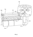
- FIG. 2 is a view of the example APU 100 of FIG. 1 showing certain internal aspects of the APU 100.
- the example propulsor 106 includes a fan assembly 200 coupled to a gearbox 202.
- the gearbox 202 is coupled to a drive shaft 204 (e.g., a turbo shaft) and the tilt shaft 108, which engages first and second tile bearings 206, 208.
- an engine 210 converts an energy source 212 into a mechanical force that rotates the drive shaft 204.
- the example drive shaft 204 of FIG. 2 engages the gear box 202 which, in turn, drives the example fan assembly 200 and/or the example tilt shaft 108.
- the energy source 212 of the APU 100 is a fuel (e.g., a carbon based fuel) carried by an internal housing or tank 214 of the rigid aerodynamic member 102. Additional or alternative energy source(s), such as a battery bank, and/or housing(s) can be utilized by the example APU 100 of FIG. 1 .
- the example flight controller 112 executes flight control application(s) and/or programming and communicates corresponding flight control instructions to the components of the example APU 100. Accordingly, the example flight controller 112 is in communication with, for example, the gearbox 202, a fuel injection system of the engine 210, the adjustable aerodynamic member 104, and/or sensor(s) associated with any of the components of the example APU 100.
- FIG. 3 is a block diagram representative of an example implementation of the example flight controller 112 of FIGS. 1 and/or 2.
- the example flight controller 112 enables the APU 100 to provide flight control capabilities to a body that is otherwise incapable of executing flight control programming (e.g., when the example APU 100 is mounted to a payload carrying shell by itself or with other APUs). Additionally or alternatively, the example flight controller 112 enables the APU 100 to collaborate with and/or take orders from another flight control system when, for example, the APU 100 is mounted to a flight-capable aircraft to supplement (e.g., provide additional, replacement and/or auxiliary lift and/or thrust) the existing propulsion system of the flight-capable aircraft.
- the example flight controller 112 executes flight control programming and/or application(s) for a plurality of different aircraft configurations and/or designs.
- the flight control programming and/or application(s) to be executed by the flight controller 112 depends on the particular configuration and/or design of the aircraft currently utilizing the APU 100.
- the example flight controller 112 of FIG. 3 includes a configuration identifier 300. As illustrated in the examples discussed below, two or more of the example APU 100 of FIGS.
- the example configuration identifier 300 identifies parameters, orientations, specifications, capabilities, etc. of the APU(s) 100 and the parameters, orientations, specifications, shapes, geometries, capabilities, etc. of the body or bodies to which the APUs 100 are mounted. In some examples, the configuration identifier 300 is manually provided with some or all of the information by, for example, a technician.
- the configuration identifier 300 includes detection logic to automatically determine information associated with the aircraft, such as a number of APU(s) 100 being utilized and/or a configuration or arrangement thereof. In such instances, the configuration identifier 300 polls components with which the APU 100 is in communication to determine whether additional APU(s) have been mounted to the aircraft. In some examples, the configuration identifier 300 determines that the corresponding APU 100 has been mounted to a flight-capable aircraft (e.g., an unmanned VTOL having its own propulsion system). That is, the example configuration identifier 300 may determine that the APU 100 is being used to supplement a base configuration of an existing aircraft and/or to replace a base configuration component of the existing aircraft.
- a flight-capable aircraft e.g., an unmanned VTOL having its own propulsion system
- such information is provided by a processing system of the aircraft and/or otherwise conveyed to the flight controller 112 (e.g., by a technician). Additionally or alternatively, the example configuration identifier 300 may actively query a detected external processing system for information regarding, for example, the base configuration of the aircraft. Additionally, the example configuration identifier 300 may be updated (e.g., periodically and/or in response to released information) with data and/or logic to enable the configuration identifier 300 to identify additional or alternative configurations.
- the example configuration identifier 300 of FIG. 3 uses the gathered information to select one or more flight control programs and/or applications for the current aircraft.
- the flight controller 112 includes a plurality of flight control programs 302 from which the configuration identifier 300 selects one or more of the appropriate flight control programs. That is, depending on the configuration, shape, number of APU(s) 100, and/or any other suitable characteristic(s), the example configuration identifier 300 of FIG. 3 selects one or more of the flight control programs 302.
- the example flight control programs 302 of FIG. 3 can be updated to include additional or alternative information (e.g., configurations) according to, for example, a schedule and/or released information. Additionally, the example flight controller 112 of FIG.
- a user interface 304 to enable a user (e.g., a designer, technician, and/or programmer) of the example APU 100 to provide customized flight control programming and/or application(s) that, in some examples, correspond to particular aircraft configuration(s), APU orientation(s), APU capabilities), etc.
- Data entered via the user interface 304 can be stored as, for example, one or more of the flight control programs 302.
- the example user interface 304 of FIG. 3 can be used to exchange additional or alternative type(s) of data with the example flight controller 112.
- the example flight controller 112 of FIG. 3 includes an execution unit 306 to execute instructions of the selected one(s) of the flight control programs 302.
- the execution unit 306 executes the selected flight control program(s) 302 to evaluate conditions associated with the APU 100 and to respond to detected condition(s). Additionally or alternatively, the example execution unit 306 executes the selected flight control program(s) 302 to receive and perform tasks associated with instructions sent to the flight controller 112.
- Example conditions associated with the APU 100 on which the execution unit 306 acts in accordance with the selected flight control program(s) 302 include weather conditions, airspeed, altitude, payload weight, and/or any other condition related to flight control operations.
- the condition data is collected via, for example, sensors deployed on the components of the APU 100 and/or the body onto which the APU 100 is mounted.
- Instructions provided to the example execution unit 306 are received from, for example, a pilot, autopilot functionality of the selected flight control program(s) 302, a flight controller of another APU 100, and/or an external flight control system (e.g., when the APU 100 is mounted to a flight capable aircraft having its own flight control computer).
- Data received from a pilot may originate on the aircraft (e.g., when the aircraft is a manned aircraft) and/or from an external system (e.g., when the aircraft is an unmanned aircraft).
- the example execution unit 306 evaluates the condition data, the provided instructions, and/or any other suitable data to identify one or more appropriate flight control responses in accordance with, for example, the selected flight control program(s) 302.
- the example execution unit 306 executes the appropriate responses by, for example, sending signal(s) to the corresponding components of the APU 100. For example, when the example execution unit 306 determines that an aircraft utilizing the APU 100 is taking off, the example execution unit 306 causes the APU 100 to generate lift by instructing the engine 206 to rotate the drive shaft 204 to thereby engage the fan assembly 200 of the propulsor 106.
- the example execution unit 306 determines that the aircraft utilizing the APU 100 is performing an inflight maneuver (e.g., a turn, climb, dive, bank, etc.)
- the example execution unit 306 causes one or more sections of the adjustable aerodynamic member 104 to adjust to a particular configuration (e.g., angular position) depending on, for example, the type of maneuver.
- the example execution unit 306 of FIG. 3 performs additional computations and provides additional signals to realize full flight control capability for the example APU 100.
- the example execution unit 306 of FIG. 3 utilizes a communicator 308 to transmit and receive information.
- the flight controllers 112 of the APUs 100 communicate (e.g., via wires or wirelessly) with each other via the corresponding communicators 308 to collaboratively control the flight of the aircraft formed by the combination of APUs 100.
- the collaboration is defined by the corresponding one or more of the flight control programs 302.
- the communicators 308 of the flight controllers 112 collaborate according to, for example, a master slave arrangement in which one of the flight controllers 112 is designated as a master device and the remaining flight controller(s) 112 are designated as slave devices.
- the communicator 308 of FIG. 3 exchanges data with processing equipment (e.g., a flight control computer) of the existing aircraft and/or other communicator(s) 308 of other APU(s) 100 also mounted to the aircraft.
- processing equipment e.g., a flight control computer
- the example communicator 308 of the example flight controller 112 may communicate with the flight control computer of the rotor craft to coordinate flight operations.
- the flight control computer of the rotor craft may assume the role of master device to the slave APU 100.
- any of the example configuration identifier 300, the example user interface 304, the example execution unit 306, the example communicator 308 and/or, more generally, the example flight controller 112 of FIG. 3 could be implemented by one or more analog or digital circuit(s), logic circuits, programmable processor(s), application specific integrated circuit(s) (ASIC(s)), programmable logic device(s) (PLD(s)) and/or field programmable logic device(s) (FPLD(s)).
- ASIC application specific integrated circuit
- PLD programmable logic device
- FPLD field programmable logic device
- the example flight controller 112 of FIG. 3 is/are hereby expressly defined to include a tangible computer readable storage device or storage disk such as a memory, a digital versatile disk (DVD), a compact disk (CD), a Blu-ray disk, etc. storing the software and/or firmware.
- the example flight controller 112 of FIG. 3 may include one or more elements, processes and/or devices in addition to, or instead of, those illustrated in FIG. 3 , and/or may include more than one of any or all of the illustrated elements, processes and devices.
- FIG. 4 A flowchart representative of an example process to implement the example flight controller 112 of FIGS. 1 , 2 and/or 3 is shown in FIG. 4 .
- the processes may be implemented using machine readable instructions that comprise a program or programs for execution by a processor such as the processor 1612 shown in the example processor platform 1600 discussed below in connection with FIG. 16 .
- the program(s) may be embodied in software stored on a tangible computer readable storage medium such as a CD-ROM, a floppy disk, a hard drive, a digital versatile disk (DVD), a Blu-ray disk, or a memory associated with the processor 1612, but the entire program(s) and/or parts thereof could alternatively be executed by a device other than the processor 1612 and/or embodied in firmware or dedicated hardware.
- a tangible computer readable storage medium such as a CD-ROM, a floppy disk, a hard drive, a digital versatile disk (DVD), a Blu-ray disk, or a memory associated with the processor 1612, but the entire program(s) and/or parts thereof could alternatively be executed by a device other than the processor 1612 and/or embodied in firmware or dedicated hardware.
- the example program(s) are described with reference to the flowchart illustrated in FIG. 4 , many other methods of implementing the example flight controller 112 may alternatively be used. For example, the order of execution of
- the example process of FIG. 4 may be implemented using coded instructions (e.g., computer and/or machine readable instructions) stored on a tangible computer readable storage medium such as a hard disk drive, a flash memory, a read-only memory (ROM), a compact disk (CD), a digital versatile disk (DVD), a cache, a random-access memory (RAM) and/or any other storage device or storage disk in which information is stored for any duration (e.g., for extended time periods, permanently, for brief instances, for temporarily buffering, and/or for caching of the information).
- a tangible computer readable storage medium is expressly defined to include any type of computer readable storage device and/or storage disk and to exclude propagating signals.
- tangible computer readable storage medium and “tangible machine readable storage medium” are used interchangeably. Additionally or alternatively, the example process of FIG. 4 may be implemented using coded instructions (e.g., computer and/or machine readable instructions) stored on a non-transitory computer and/or machine readable medium such as a hard disk drive, a flash memory, a read-only memory, a compact disk, a digital versatile disk, a cache, a random-access memory and/or any other storage device or storage disk in which information is stored for any duration (e.g., for extended time periods, permanently, for brief instances, for temporarily buffering, and/or for caching of the information).
- coded instructions e.g., computer and/or machine readable instructions
- a non-transitory computer and/or machine readable medium such as a hard disk drive, a flash memory, a read-only memory, a compact disk, a digital versatile disk, a cache, a random-access memory and/or any other storage device or storage disk in which information is
- non-transitory computer readable medium is expressly defined to include any type of computer readable device or disk and to exclude propagating signals.
- phrase “at least” is used as the transition term in a preamble of a claim, it is open-ended in the same manner as the term “comprising” is open ended.
- the example of FIG. 4 begins with an indication that the example APU 100 of FIGS. 1 and/or 2 is activated (block 400). Such an indication corresponds to, for example, the example APU 100 being initiated for the first time or the example APU 100 being repurposed for a new task and/or aircraft.
- the example configuration identifier 300 of the flight controller 112 determines a configuration of the aircraft currently utilizing the APU 100 (block 402).
- the information determined by the example configuration identifier 300 includes, for example, placement information indicative of an arrangement of the APU(s) 100 and/or propulsion system(s) of an existing aircraft, shape information indicative of geometries of the body to which the APU(s) 100 are mounted, master-slave relationship(s) between flight controllers, etc.
- the configuration determined by the example configuration identifier 300 may correspond to an aircraft formed with the APU 100 (and/or other APUs) as the sole source(s) of propulsion and flight control.
- the configuration determined by the example configuration identifier 300 may correspond to an independently (e.g., without the APU 100) flight-capable aircraft being supplemented by the APU 100.
- the example flight controller 112 selects one(s) of the flight control programs 302 corresponding to the APU(s) 100 being the sole source(s) of propulsion and/or flight control (block 406).
- customized flight control program(s) and/or program information is provided to the flight controller 112 by, for example, a designer (e.g., via the user interface 304) of the aircraft formed using the example APU 100.
- the provided flight control information is selected as the appropriate flight control program and/or used in conjunction with one or more of the stored flight control program(s).
- the example communicator 308 establishes communication with any other APU(s) 100 of the aircraft identified by, for example, the configuration identifier 300 and/or a user via the user interface 306 (block 408).
- the communicator 308 enforces a security protocol that requires the APU(s) 100 to pass an authorization procedure before the communication can be established. Additionally, the example communicator 308 may require periodic security events in which the APU(s) 100 are required to be reauthorized.
- the selected flight control program(s) are executed (block 410).
- Execution of the flight control program(s) 302 involves, for example, detecting conditions, receiving pilot input, calculating responses to condition(s) and/or input(s), operating components, etc.
- the example flight control program(s) provided by the example APU(s) 100 are capable of flying the body to which the APU(s) 100 are coupled (e.g., mounted) without receiving any external flight control capability from an external source, such as the body.
- the APU(s) 100 can be mounted to a body void of any flight control processing, void of any energy source and void of propulsion sources, and can enable such a body to be fully flight capable.
- the example communicator 308 establishes communication with a processing system of the aircraft to which the APU 100 is coupled (e.g., mounted) (block 412).
- the communicator 308 and the processing system of the aircraft can establish a session (e.g., a handshake) during which data related to the respective components is exchanged.
- the exchange of information enables the configuration identifier 300 to collect additional information regarding aspect(s) and/or characteristic(s) of the aircraft to which the APU 100 is coupled.
- a session e.g., a handshake
- the example communicator 308 also obtains flight control information from the processing system of the aircraft to which the APU 100 is coupled. That is, the aircraft to which the APU 100 is mounted may include a flight controller of its own that informs the flight controller 112 of the APU 100 of the native flight control programming of the aircraft.
- the example flight controller 112 selects one or more of the flight control programs 302 for the APU 100 (block 416).
- one or more aspects of the selected flight control program(s) 302 may be provided by data received from the flight control system of the aircraft to which the APU 100 is mounted.
- one or more physical attributes of the aircraft may be provided to the selected flight control program(s) 302, which use the physical attribute information as input for one or more flight control calculations.
- the selected flight control program(s) are executed (block 410).
- the example APU 100 is capable of autonomously providing flight capabilities to a body without external input
- the example flight control program(s) 302 of the example APU 100 are also capable of being executed in conjunction with the flight control capabilities of the aircraft to which the APU 100 is coupled.
- the selected flight control programming is executed until a shutdown is desired and/or required or when a mode switch is detected (block 418). If a shutdown is not desired or required, the selected flight control program(s) continue execution (block 410).
- a shutdown may be desired when the corresponding aircraft is powered down and/or in need of maintenance.
- a mode switch may occur when, for example, the APU 100 is detached (e.g., mid-flight) from a flight capable aircraft to switch from a supplementary mode to a solitary mode. Such a scenario is described below in connection with FIG. 15 . If a shutdown and/or mode switch occurs, control passes to block 400.
- FIG. 5A is a first perspective of an example aircraft formed using the example autonomous propulsion units disclosed herein.
- the example aircraft of FIG. 5A can be referred to as a tri-tail sitter 500.
- the example tri-tail sitter 500 of FIG. 5A includes three of the example APU 100 of FIGS. 1 and/or 2.
- the example tri-tail sitter 500 of FIG. 5A includes a first APU 502, a second APU 504 and a third APU 506.
- the example APUs 502-506 include respective propulsors 508-512 and corresponding aerodynamic members 514-518 (as described above in connection with FIG. 2 ).
- each of the aerodynamic members 514-518 is coupled to a body 520.
- the body 520 is a payload carrying shell void of any flight control processing and void of any energy. Accordingly, the APUs 502-506 do not receive flight control instructions or energy source (e.g., fuel) from the body 520. As described above, the example flight controllers 112 of the APUs 502-506 identify the configuration of the aircraft of FIG. 5A as a tri-tail sitter, obtain information about the body 520 (e.g., via the user interface 304), select the appropriate one(s) of the flight control programs 302, establish communication with each other, and execute the selected flight control program(s) 302. In the illustrated example of FIG.
- the first APU 502 is selected as the master device, while the second and third APUs 504, 506 are slave devices for purposes of the flight control programming.
- the flight controllers 112 of the respective APUs 502-506 collaborate to implement the flight control of the tri-tail sitter 500 in accordance with, for example, detected condition(s) and/or input(s) received from a pilot (e.g., a remotely located pilot providing input from a remote location) and/or an auto-pilot application.
- a pilot e.g., a remotely located pilot providing input from a remote location
- an auto-pilot application A second perspective of the example tri-tail sitter 500 is shown in FIG. 5B .
- FIG. 6A is a first perspective of another example aircraft formed using the example autonomous propulsion units disclosed herein.
- the example aircraft of FIG. 6A can be referred to as a quad-tail sitter 600.
- the example quad-tail sitter 600 of FIG. 6A is similar to the example tri-tail sitter 500 of FIGS. 5A and 5B in that the example quad-tail sitter 600 of FIG. 6A includes a plurality of the example APUs 100 of FIGS. 1 and/or 2 (designated with reference numerals 602-608 in FIG. 6A ), each having a respective propulsor 610-616 and corresponding aerodynamic members 618-624, and each being coupled to a payload carrying shell 626 void of any flight control processing and void of any energy.
- the APUs 602-608 of FIG. 6A do not receive flight control instructions or energy source (e.g., fuel) from the body 626 to which the APUs 602-608 are coupled.
- flight control instructions or energy source e.g., fuel
- the number and arrangement of the APUs 602-608 in FIG. 6A are different than APUs 502-506 in FIGS. 5A and 5B .
- the example flight controllers 112 of the APUs 602-608 of FIG. 6A identify the configuration of the aircraft of FIG. 6A as a quad-tail sitter and select the appropriate flight control program(s) according to the quad-tail sitter configuration.
- a second perspective of the example quad-tail sitter 600 is shown in FIG. 6B .
- FIG. 7A is a first perspective of another example aircraft formed using the example autonomous propulsion units disclosed herein.
- the example aircraft of FIG. 7A can be referred to as a dual-tail sitter 700.
- the example dual-tail sitter 700 of FIG. 7A is similar to the example tri-tail sitter 500 of FIGS. 5A and 5B and the example quad-tail sitter 600 of FIGS. 6A and 6B in that the example dual-tail sitter 700 of FIG. 7A includes a plurality of the example APUs 100 of FIGS. 1 and/or 2 (designated with reference numerals 702, 704 in FIG.
- the APUs 702, 704 of FIG. 7A do not receive flight control instructions or energy source (e.g., fuel) from the body 714 to which the APUs 702, 704 are coupled.
- flight control instructions or energy source e.g., fuel
- the example body 714 of the example dual-tail sitter 700 includes or is coupled to a fin 716 to, for example, provide stability and/or one or additional adjustable aerodynamic surfaces.
- the example flight controllers of the APUs 702, 704 of FIG. 7A identify the configuration of the aircraft of FIG. 7A as a dual-tail sitter having the fin 716 and select the appropriate flight control program(s) according to the dual-tail sitter configuration.
- a second perspective of the example dual-tail sitter 700 is shown in FIG. 7B .
- FIG. 8A is a first perspective of another example aircraft formed using the example autonomous propulsion units disclosed herein.
- the example aircraft of FIG. 8A can be referred to as a quad-tilt duct aircraft 800.
- the example quad-tilt duct aircraft 800 of FIG. 8A includes four of the example APUs 100 of FIGS. 1 and/or 2 (designated with reference numerals 802-808 in FIG. 8A ), each having a respective propulsor 810-816 and corresponding aerodynamic members 818-824.
- the propulsors 810-816 are shown in a tilted position relative to, for example, the aerodynamic members 818-824.
- the tilted position of the propulsors 810-816 correspond to a lift position in which the quad-tilt duct aircraft 800 is taking off, landing, or performing a vertical maneuver.
- FIGS. 8B and 8C provide other perspectives of the example quad-tilt duct aircraft 800 of FIG. 8A in which the propulsors 810-816 are in a different tilt position.
- FIGS. 8B and 8C show the propulsors 810-816 positioned to provide (mainly) horizontal thrust during, for example, an acceleration maneuver.
- each of the aerodynamic members 818-824 is coupled to a body 826.
- the body 826 is a payload carrying shell void of any flight control processing and void of any energy source. Accordingly, the APUs 802-808 do not receive flight control instructions or energy (e.g., fuel) from the body 826. Accordingly, the example flight controllers 112 of the APUs 802-808 identify the configuration of the aircraft of FIG. 8A as a quad-tilt duct aircraft 800 and select the appropriate flight control program(s) 302 according to the quad-tilt duct configuration.
- flight control instructions or energy e.g., fuel
- FIG. 9 is another example aircraft formed using the example autonomous propulsion units disclosed herein.
- the example aircraft of FIG. 9 can be referred to as a quad-tilt duct aircraft 900.
- the example quad-tilt duct aircraft 900 of FIG. 9 includes four of the example APUs 100 of FIGS. 1 and/or 2 (designated with reference numerals 902-908 in FIG. 9 ), each having a respective propulsor 910-916 and corresponding aerodynamic members 918-924. Similar to the propulsors 802-808 of FIG. 8A , the propulsors 910-916 of FIG. 9 are shown in a tilted position corresponding to a lift position, and can be moved to a different tilt position. In the example of FIG.
- each of the aerodynamic members 918-924 is coupled to a body 926.
- the body 926 is equipped to carry a pilot and/or a team.
- the example quad-tilt aircraft 900 may also be implemented as an unmanned aircraft.
- the example body 926 includes controls to be used by the pilot and/or team to provide input to components of the body 926 and/or the flight controllers 112 of the APUs 902-908 via, for example, the user interface 304 described above in connection with FIG. 3 .
- information received via the user interface 304 from the pilot and/or team is input for the selected flight control program(s).
- the flight controllers 112 of the example APUs 902-908 receive input from the body 926, the received input is not originated from a flight control program (e.g., is not a flight control instruction) but rather an input from a pilot, such as a movement of a stick, gear, knob, electronic instrumentation, etc. Accordingly, the APUs 902-908 do not receive flight control instructions (e.g., data generated by a flight control program) from the body 926, but can receive input from a pilot.
- the example flight controllers 112 of the APUs 902-908 identify the configuration of the aircraft of FIG. 9 as a manned quad-tilt duct aircraft 900 and select the appropriate flight control program(s).
- the flight controllers 112 of the respective APUs 902-908 collaborate (e.g., with each other and the input from the pilot) to implement the flight control of the quad-tilt duct aircraft 900.
- FIG. 10 is another example aircraft formed using the example autonomous propulsion units disclosed herein.
- the example aircraft of FIG. 10 can be referred to as a dual-tilt duct aircraft 1000.
- the example dual-tilt duct aircraft 1000 of FIG. 10 includes two of the example APUs 100 of FIGS. 1 and/or 2 (designated with reference numerals 1002, 1004 in FIG. 10 ) each having a respective propulsor 1006, 1008 and corresponding aerodynamic members 1010, 1012.
- the example APUs 1002, 1004 of FIG. 10 are similar to the APUs 902-908 of FIG. 9 in that the propulsors 1006, 1008 can be tilted to different positions relative to, for example, the respective aerodynamic members 1010, 1012.
- FIG. 10 In the example of FIG.
- each of the aerodynamic members 1010, 1012 is coupled to a body 1014 equipped to carry a pilot and/or a team and including controls to be used by the pilot and/or team to provide input to the flight controllers 112 of the APUs 1002, 1004.
- the example dual-tilt duct aircraft 1000 may also be implemented as an unmanned aircraft.
- the example flight controllers 112 of the APUs 1002, 1004 identify the configuration of the aircraft of FIG. 10 as a manned dual-tilt duct aircraft and select the appropriate flight control program(s).
- the flight controllers 112 of the respective APUs 1002, 1004 collaborate (e.g., with each other and the input from the pilot) to implement the flight control of the dual-tilt duct aircraft 1000.
- FIG. 11 is another example aircraft formed using the example autonomous propulsion units disclosed herein.
- the example aircraft of FIG. 11 can be referred to as a dual-tilt wing aircraft 1100.
- the example dual-tilt wing aircraft 1100 of FIG. 11 includes two of the example APUs 100 of FIGS. 1 and/or 2 (designated with reference numerals 1102, 1104 in FIG. 11 ) each having a respective propulsor 1106, 1108 and corresponding aerodynamic members 1110, 1112.
- the example dual-tilt wing aircraft 1100 of FIG. 11 is similar to the dual-tilt duct aircraft 1000 of FIG. 10 .
- the example dual-tilt wing aircraft 1100 may also be implemented as an unmanned aircraft.
- the example flight controllers 112 of the APUs 1102, 1104 identify the configuration of the aircraft of FIG. 11 as a manned dual-tilt wing aircraft and select the appropriate flight control program(s).
- the flight controllers of the respective APUs 1102, 1104 collaborate (e.g., with each other and the input from the pilot) to implement the flight control of the dual-tilt wing aircraft 1100.
- FIG. 12A is another example aircraft formed using the example autonomous propulsion units disclosed herein.
- the example aircraft of FIG. 12A can be referred to as a tri-fuselage aircraft 1200.
- the example tri-fuselage aircraft 1200 of FIG. 12A includes three of the example APUs 100 of FIGS. 1 and/or 2 (designated with reference numerals 1202-1206 in FIG. 9 ), each having a respective propulsor 1208-1212 and corresponding aerodynamic members 1214-1218.
- the three APUs 1202-1206 form an assembly 1220 that can be tilted different positions relative to a body 1222 to which the assembly 1220 is coupled (e.g., hinge or pivot mounted).
- all of the APUs 1202-1206 can be moved at the same time by moving the assembly 1220 from one hinged position to another.
- the assembly 1220 is shown in a first position in FIG. 12A
- FIG. 12B illustrates the assembly 1220 in a second, different position.
- the position of the assembly 1220 in FIG. 12A corresponds to the APUs 1202-1206 providing (mainly) lateral thrust for the body 1222.
- the position of the assembly 1220 of FIG. 12B corresponds to the APUs 1202-1206 providing (mainly) vertical lift for the body 1222.
- the assembly 1220 can be moved to incremental positions within a range defined by the first and second positions of FIGS. 12A and 12B , respectively.
- the positions of the assembly 1220 may be limited to those shown in FIGS. 12A and 12B .
- the body 1222 is equipped to carry a pilot and/or a team.
- the example tri-fuselage aircraft 1200 may also be implemented as an unmanned aircraft.
- the example flight controllers of the APUs 1202-1206 identify the configuration of the aircraft of FIG. 12A as a tri-fuselage aircraft and select the appropriate flight control program(s).
- the flight controllers of the respective APUs 1202-1206 collaborate (e.g., with each other and the input from the pilot) to implement the flight control of the tri-fuselage aircraft 1200.
- FIG. 13 is another example aircraft formed using the example autonomous propulsion units disclosed herein.
- the example aircraft of FIG. 13 is a rotor craft 1300 having its own propulsion system generally referred to herein with reference numeral 1302.
- the example rotor craft 1300 of FIG. 13 includes two of the example APUs 100 of FIGS. 1 and/or 2 (designated with reference numerals 1304, 1306 in FIG. 13 ), each having a respective propulsor 1308, 1310 and corresponding aerodynamic members 1312, 1314.
- the two APUs 1304, 1306 have been mounted to the rotor craft 1300 to supplement the existing propulsion system 1302. That is, the two APUs 1304, 1306 of FIG.
- a body 1316 to which the APUs 1304, 1306 are mounted is equipped to carry a pilot and/or a team and has its own flight control capabilities (e.g., to control the propulsion system 1302 and/or additional components).
- the example configuration identifiers 300 of the flight controllers 112 of the APUs 1304, 1306 determine that the APUs 1304, 1306 are being implemented on the type of rotor craft shown in FIG.
- APU flight controllers 112 communicates with the existing flight control system of the rotor craft 1300.
- the APUs 1304, 1306 are slave devices to the master flight control system of the rotor craft 1300.
- the flight controllers 112 of the respective APUs 1304, 1306 collaborate (e.g., with each other and the input from the pilot of the rotor craft 1300) to implement the flight control of the rotor craft 1300.
- FIG. 14 is another rotor craft 1400 formed using the example autonomous propulsion units disclosed herein.
- the example rotor craft of FIG. 14 has its own propulsion system generally referred to herein with reference numeral 1402.
- the example propulsion system of FIG. 14 includes two blades controlled by a flight control system of the rotor craft 1400.
- the example rotor craft 1400 of FIG. 14 includes two of the example APUs 100 of FIGS. 1 and/or 2 (designated with reference numerals 1404, 1406 in FIG. 14 ), each having a respective propulsor 1408, 1410 and corresponding aerodynamic members 1412, 1414.
- example APUs 1404, 1406 have been mounted to the rotor craft 1400 to supplement the existing propulsion system 1402.
- the example configuration identifiers 300 of the flight controllers 112 of the APUs 1404, 1406 determine that the APUs 1404, 1406 are being implemented on the type of rotor craft shown in FIG. 14 and select the appropriate flight program(s) 302.
- the flight controllers 112 of the respective APUs 1404, 1406 collaborate (e.g., with each other and the input from the pilot of the rotor craft 1400) to implement the flight control of the rotor craft 1400.
- FIG. 15 illustrates an APU assembly 1500 that can be detachably mounted to, for example, an example rotor craft 1502 shown in FIG. 15 .
- the rotor craft 1502 has a native flight control system to control, among other components, a native propulsion system 1504.
- the example APU assembly 1500 of FIG. 15 includes two of the example APUs 100 of FIGS. 1 and/or 2 (designated with reference numerals 1504, 1506 in FIG. 15 ).
- the example APU assembly 1500 of FIG. 5 When coupled to the rotor craft 1500, the example APU assembly 1500 of FIG. 5 provides auxiliary, additional and/or replacement thrust and/or lift to the rotor craft 1502 in a similar fashion as the APUs 1404, 1406 of FIG. 14 .
- the APUs 1504, 1506 are in a first mode, which may be referred to as a supplementary mode.
- the example APU assembly 1500 of FIG. 15 may be detached from the rotor craft 1502 mid-flight.
- the example APU assembly 1500 of FIG. 15 becomes an unmanned, flight capable aircraft due to the autonomous capabilities of the APUs 1504, 1506.
- the APU assembly 1500 detaches from the rotor craft 1502
- the APU assembly 1500 is in a second mode, which may be referred to as a solitary mode.
- the APUs 1504, 1506 provide supplementary propulsion and/or flight control capabilities.
- the APUs 1504, 1506 are the sole source of propulsion and flight control capability.
- the configuration identifier 300 of the flight controller 112 can detect whether the APU assembly 1500 is in the supplementary mode or the solitary mode and may select appropriate flight control program(s) for each mode.
- FIG. 16 is a block diagram of an example processor platform 1600 capable of executing the instructions of FIG. 4 to implement the example flight controller 112 of FIGS. 1 and/or 2.
- the processor platform 1600 can be any suitable computing device such as, for example, a computer, a system on chip (SoC) and/or ASIC.
- SoC system on chip
- the processor platform 1600 of the illustrated example includes a processor 1612.
- the processor 1612 of the illustrated example is hardware.
- the processor 1612 can be implemented by one or more integrated circuits, logic circuits, microprocessors or controllers from any desired family or manufacturer.
- the processor 1612 of the illustrated example includes a local memory 1613 (e.g., a cache).
- the processor 1612 of the illustrated example is in communication with a main memory including a volatile memory 1614 and a non-volatile memory 1616 via a bus 1618.
- the volatile memory 1614 may be implemented by Synchronous Dynamic Random Access Memory (SDRAM), Dynamic Random Access Memory (DRAM), RAMBUS Dynamic Random Access Memory (RDRAM) and/or any other type of random access memory device.
- the non-volatile memory 1616 may be implemented by flash memory and/or any other desired type of memory device. Access to the main memory 1614, 1616 is controlled by a memory controller.
- the processor platform 1600 of the illustrated example also includes an interface circuit 1620.
- the interface circuit 1620 may be implemented by any type of interface standard, such as an Ethernet interface, a universal serial bus (USB), and/or a PCI express interface.
- one or more input devices 1622 are connected to the interface circuit 1620.
- the input device(s) 1622 permit(s) a user to enter data and commands into the processor 1612.
- the input device(s) 1622 can be implemented by, for example, a sensor, a button, etc.
- One or more output devices 1624 are also connected to the interface circuit 1620 of the illustrated example.
- the output devices 1624 can be implemented, for example, a light emitting diode (LED).
- the interface circuit 1620 of the illustrated example also includes a communication device such as a transmitter, a receiver, a transceiver, and/or network interface card to facilitate exchange of data with external machines (e.g., computing devices of any kind) via a network 1626 (e.g., an Ethernet connection, a digital subscriber line (DSL), a telephone line, coaxial cable, a cellular telephone system, etc.).
- a communication device such as a transmitter, a receiver, a transceiver, and/or network interface card to facilitate exchange of data with external machines (e.g., computing devices of any kind) via a network 1626 (e.g., an Ethernet connection, a digital subscriber line (DSL), a telephone line, coaxial cable, a cellular telephone system, etc.).
- DSL digital subscriber line
- Coded instructions 1632 to implement the process of FIG. 4 may be stored in the volatile memory 1614 and/or in the non-volatile memory 1616 and/or a removable storage medium.
Abstract
Description
- This disclosure relates generally to aircraft and, more particularly, autonomous propulsion apparatus and methods.
- Aircraft components and systems are conventionally developed specifically for a single configuration or purpose for a particular aircraft. For example, development of a particular helicopter involves designing a particular rotor based on specifications and/or requirements for that particular helicopter (e.g., size, power, and/or other requirements or desires).
- Autonomous propulsion apparatus and methods are disclosed. A disclosed example autonomous propulsion apparatus includes a flight controller capable of executing flight control instructions stored in a memory of the autonomous propulsion unit; and a propulsor to generate propulsion in accordance with the instructions for a payload carrier to which the autonomous propulsion unit is coupled, wherein the flight controller is to provide flight control for the propulsor in an absence of flight control instructions from the payload carrier.
- A disclosed example aircraft includes a body; a first propulsion unit mounted to the body, the first propulsion unit including a first flight controller; and a second propulsion unit mounted to the body, the second propulsion unit including a second flight controller, wherein the first flight controller is to communicate with the second flight controller to provide flight capabilities to the body without receiving a flight control instruction from the body.
- A disclosed example method for a flight controller implemented on an autonomous propulsion unit includes determining a configuration of an aircraft formed by the autonomous propulsion unit, wherein the configuration indicates a number of autonomous propulsion units mounted to a body; selecting a flight control program based on the determined configuration; and executing the selected flight control program to provide flight capability to the aircraft without receiving flight control instructions from the body.
- The invention can involve an autonomous propulsion unit that may include a flight controller capable of executing flight control instructions stored in a memory of the autonomous propulsion unit; and a propulsor to generate propulsion in accordance with the instructions for a payload carrier to which the autonomous propulsion unit is coupled, wherein the flight controller is to provide flight control for the propulsor in an absence of flight control instructions from the payload carrier. The memory may include a first flight control program corresponding to a first aircraft configuration and a second flight control program corresponding to a second aircraft configuration. The first aircraft configuration may include a first arrangement of the autonomous propulsion unit and the payload carrier, and the second aircraft configuration includes a second arrangement of the autonomous propulsion unit and the payload carrier different from the first arrangement. The autonomous propulsion unit may also include an adjustable aerodynamic surface, wherein the flight controller is capable of providing flight control for the aerodynamic surface in an absence of flight control instructions from the payload carrier. The autonomous propulsion unit may also include an internal housing to carry an energy source, wherein the flight controller is to control use of the energy source by the propulsor in an absence of flight control instructions from the payload carrier. The autonomous propulsion unit, may also include a tilt mechanism to enable the propulsor to be positioned at different angles relative to the payload carrier, wherein the flight controller is to control the tilt mechanism in an absence of flight control instructions from the payload carrier.
- The invention can involve an aircraft that may include a body; a first propulsion unit mounted to the body, the first propulsion unit including a first flight controller; and a second propulsion unit mounted to the body, the second propulsion unit including a second flight controller, wherein the first flight controller is to communicate with the second flight controller to provide flight capabilities to the body without receiving a flight control instruction from the body. In some embodiments, the body may not include a flight control processing system. The first propulsion unit may be removably mounted to the body. The first flight controller may be designated as a master device and the second flight controller may be designated as a slave device. The first and second propulsion units may be sole sources of propulsion for the aircraft. The propulsion units may be tiltable duct fans. The aircraft may be removably coupled to a second aircraft such that the aircraft can be removed from the second aircraft mid-flight. The second aircraft may include a native flight controller.
- The invention can involve a method that may include determining a configuration of an aircraft formed by an autonomous propulsion unit, wherein the configuration indicates a number of autonomous propulsion units mounted to a body; selecting a flight control program based on the determined configuration; and executing the selected flight control program to provide flight capability to the autonomous propulsion unit without receiving flight control instructions from the body. The configuration may indicate an arrangement of the autonomous propulsion units mounted to the body, and may also include selecting the flight control program based on the determined arrangement. The method may also include determining that the autonomous propulsion unit has been used to form a second aircraft having a second configuration different that the first configuration. The method may also include selecting a second flight control program different than the first flight control program for the second aircraft, and executing the second flight control program to provide flight capability to the second aircraft. The method may also include establishing communication between the autonomous propulsion unit and a second autonomous propulsion unit mounted to the body. Executing the selected flight control program may include collaborating with the second autonomous propulsion unit.
-
-
FIG. 1 is an illustration of an example autonomous propulsion unit (APU) constructed in accordance with teachings of this disclosure. -
FIG. 2 is another illustration of the example APU ofFIG. 1 . -
FIG. 3 is a block diagram of an example implementation of the example flight controller ofFIGS. 1 and/or 2. -
FIG. 4 is a flowchart representative of an example process that may be performed to implement the example flight controller ofFIGS. 1 ,2 and/or 3. -
FIG. 5A is an illustration from a first perspective of an example tri-tail sitter constructed using the example APU ofFIGS. 1 and/or 2. -
FIG. 5B is an illustration of the example tri-tail sitter ofFIG. 5A from a second perspective. -
FIG. 6A is an illustration from a first perspective of an example quad-tail sitter constructed using the example APU ofFIGS. 1 and/or 2. -
FIG. 6B is an illustration of the example quad-tail sitter ofFIG. 6A from a second perspective. -
FIG. 7A is an illustration from a first perspective of an example dual-tail sitter constructed using the example APU ofFIGS. 1 and/or 2. -
FIG. 7B is an illustration of the example dual-tail sitter ofFIG. 7A from a second perspective. -
FIG. 8A is an illustration from a first perspective of an example quad-tilt duct aircraft constructed using the example APU ofFIGS. 1 and/or 2. -
FIG. 8B is an illustration of the example quad-tilt duct aircraft ofFIG. 8A from a second perspective. -
FIG. 8C is an illustration of the example quad-tilt duct aircraft ofFIG. 8A from a third perspective. -
FIG. 9 is an illustration of another example quad-tilt duct aircraft constructed using the example APU ofFIGS. 1 and/or 2. -
FIG. 10 is an illustration of an example dual-tilt duct aircraft constructed using the example APU ofFIGS. 1 and/or 2. -
FIG. 11 is an illustration of an example dual-tilt wing aircraft constructed using the example APU ofFIGS. 1 and/or 2. -
FIG. 12A is an illustration of an example tri-fuselage aircraft constructed using the example APU ofFIGS. 1 and/or 2. -
FIG. 12B is an illustration of the example tri-fuselage aircraft ofFIG. 12A in a different configuration. -
FIG. 13 is an illustration of an example rotor craft having the example APU ofFIGS. 1 and/or 2 mounted thereto. -
FIG. 14 is an illustration of another example rotor craft having the example APU ofFIGS. 1 and/or 2 mounted thereto. -
FIG. 15 is an illustration of an example APU assembly constructed in accordance with teachings of this disclosure. -
FIG. 16 is an example processing platform capable of implementing the example flight controller ofFIGS. 1 ,2 and/or 3. - To clarify multiple layers and regions, the thicknesses of the layers are enlarged in the drawings. Accordingly, the structures illustrated in the drawings are not drawn to scale and, instead, are drawn to clarify the teachings of this disclosure. Wherever possible, the same reference numbers will be used throughout the drawing(s) and accompanying written description to refer to the same or like parts. As used in this patent, stating that any part (e.g., a layer, film, or area) is in any way positioned on (e.g., positioned on, located on, disposed on, attached to, or formed on, etc.) another part, means that the referenced part is either in contact with the other part, or that the referenced part is adjacent the other part with one or more intermediate part(s) located therebetween. Stating that any part is in contact with another part means that there is no intermediate part between the two parts.
- Example apparatus disclosed herein are self-contained, autonomous propulsion units that independently provide propulsion and/or flight capabilities to a body, such as a payload carrying shell that is incapable of flight in the absence of external source(s) of propulsion and/or flight control capabilities. Examples disclosed herein are autonomous or self-contained in that, as standalone devices, the examples disclosed herein provide propulsion (e.g., thrust and/or lift) and/or flight control capability to a body to which the unit is mounted without relying on external systems (e.g., systems other than the example autonomous units disclosed herein). For example, autonomous units disclosed herein provide propulsion and/or flight capability to a body without relying on external processing capabilities (e.g., without relying on an external flight computer), without receiving power from an external power source, and/or without relying on an external energy source. Instead, the examples disclosed herein are self-contained in that each unit includes all of the components needed to provide propulsion and/or flight capability to an attached body, even when the attached body is, for example, an empty shell configured for carrying payload. As described in detail below, example propulsion units disclosed herein include their own energy source (e.g., battery and/or fossil fuel), their own power plant (e.g., a motor, engine and/or other converter of stored energy into a mechanical force), their own propulsor (e.g., a duct fan coupled to a turbo shaft), their own flight-control-capable logic circuit (e.g., processor(s) having flight control programming and/or applications), their own aerodynamic surface(s) (e.g., a rigid wing and/or an adjustable flap), their own support structure (e.g., landing gear), and/or additional or alternative components to enable autonomous provision of propulsion and/or flight control.
- The example autonomous propulsion units disclosed herein can be combined or arranged on any suitable body or structure for which propulsion and/or flight capability is desired. For example, a plurality of the example autonomous propulsion units disclosed herein can be mounted to a structure that is not independently capable of flight. For example, the structure may be a payload carrying shell void of any energy source or processing capability. In such instances, the example propulsion units can be mounted to the payload carrying shell in any desired configuration to provide the flight-incapable shell with flight capability without receiving, for example, any electronic input (e.g., flight control instructions) or power from the payload carrying shell. Instead, the example propulsion units disclosed herein are self-contained and autonomous and provide flight capability to the payload carrying shell via the components contained therein and, in some examples, by communicating with each other. In other words, flight control processing components of the example autonomous propulsion units disclosed herein may embody the entire flight control processing capabilities of an aircraft assembled using the examples disclosed herein. The examples disclosed herein are especially useful for flight personnel (e.g., designers, technicians, etc.) deployed in the field (e.g., a remotely located base) that require particular airborne capabilities for a particular task but do not have access to inventory and/or a functional aircraft having the required capabilities. In such instances, the flight personnel can design and/or assemble an aircraft using one or more of the autonomous propulsion units disclosed herein. Example implementations of such aircraft created using the examples disclosed herein are described below.
- Additionally or alternatively, the example self-contained, autonomous propulsion units disclosed herein can supplement system(s) of an existing aircraft that is independently capable of flight (e.g., has a native propulsion system and/or native flight control processing capabilities). For example, the example apparatus disclosed herein can supplement such an aircraft by providing auxiliary, additional and/or replacement thrust and/or lift. For example, the autonomous propulsion units disclosed herein may be mounted (e.g., removably bolted) to an aircraft having its own (e.g., native) propulsion system(s) that is tasked with carrying a particularly heavy payload (e.g., a payload that exceeds or approaches the lift capabilities of the aircraft). In such instances, one or more of the example autonomous propulsion units disclosed herein can be temporarily added to the aircraft to provide additional thrust and/or lift such that the aircraft can perform the difficult task without straining (e.g., approaching the structural integrity limits of) the aircraft. When the particularly heavy payload has been delivered, the example autonomous propulsion units disclosed herein may be removed or disengaged from the aircraft, if desired, leaving the aircraft to operate according to a base configuration (e.g., with only the dedicated, existing propulsion system of the aircraft). Example uses of the autonomous propulsion units disclosed herein to supplement base configurations of aircraft are described below.
- Additionally or alternatively, the example autonomous propulsion units disclosed herein can change from (1) providing supplementary propulsion and/or flight control capabilities to an independently flight-capable aircraft to (2) being the sole source of propulsion and/or flight control capability for a flight incapable aircraft that disconnects from the flight-capable aircraft mid-flight. For example, an assembly made from the propulsion units disclosed herein may be detachably mounted (e.g., removably bolted) to an aircraft having its own (e.g., native) propulsion system(s) such that the assembly can be detached from the aircraft mid-flight and operated as a standalone aircraft (e.g., an unmanned aircraft). In such instances, the example propulsion units change from operating in a supplementary mode (e.g., when mounted to the flight-capable aircraft) to a solitary mode (e.g., when disengaged from the flight-capable aircraft). Example uses of the autonomous propulsion units disclosed herein to interchangeably operate in different modes are described below.
-
FIG. 1 illustrates an example autonomous propulsion unit (APU) 100 constructed in accordance with teachings this disclosure. Theexample APU 100 ofFIG. 1 includes a rigidaerodynamic member 102 and an adjustableaerodynamic member 104. In the example ofFIG. 1 , the rigidaerodynamic member 102 includes an internal housing (shown inFIG. 2 ) to carry an energy source, such as fuel, a battery bank, and/or any other suitable source of energy. In some examples, the adjustableaerodynamic member 104 is a single member that can be adjusted to different positions to provide configurations corresponding to, for example, stage(s) of flight and/or maneuver(s). In some examples, the adjustableaerodynamic surface 104 includes a plurality (e.g., three) of independently adjustable sections (e.g., flaps) to provide a plurality of configurations, each of which corresponds to, for example, stage(s) of flight and/or maneuver(s). - In the example of
FIG. 1 , apropulsor 106 is coupled to one or both of theaerodynamic members example propulsor 106 ofFIG. 1 is a duct fan. However, any suitable type ofpropulsor 106 can be utilized by theexample APU 100. In the example ofFIG. 1 , thepropulsor 106 is tiltable relative to, for example, one or both of theaerodynamic members FIG. 2 and discussed further below). However, theexample APU 100 ofFIG. 1 may not include thetilt shaft 108 and thepropulsor 106 may be rigidly mounted to, for example, the rigidaerodynamic member 102. Theexample APU 100 ofFIG. 1 also includes asupport structure 110. In the example ofFIG. 1 , thesupport structure 110 is a wheel assembly to facilitate movement, storage, and/or landing of a craft utilizing theexample APU 100. Additional or alternative support structures may be included on theAPU 100. - Additionally, the
example APU 100 ofFIG. 1 includes aflight controller 112 that provides flight control capabilities. That is, theexample flight controller 112 ofFIG. 1 executes flight control programming and/or application(s) to control the components (e.g., thepropulsor 106, thetilt shaft 108, the adjustableaerodynamic member 104, etc.) of theAPU 100 based on, for example, condition(s) detected via sensor(s) and/or pilot input(s). While shown as housed in the rigidaerodynamic member 102 of theAPU 100 inFIG. 1 , theexample flight controller 112 can be located at any suitable position within or on any component of theexample APU 100. Theexample flight controller 112 ofFIG. 1 is capable of providing full flight control to theAPU 100 without relying on or receiving data (e.g., instructions) from an external flight control source. In particular, theexample flight controller 112 ofFIG. 1 is loaded with application(s) and/or programming (e.g., which can be updated and/or modified by, for example, a ground based memory system of computing platform) that enable theexample APU 100 to provide full flight control to a payload carrying shell or body void of any flight computer and/or processing capabilities. For example, even when mounted to an empty shell, theexample APU 100 ofFIG. 1 and theflight controller 112 thereof provide flight capability to the aircraft formed by theexample APU 100 and the shell. Further, as theexample APU 100 ofFIG. 1 includes its own energy source and itsown propulsor 106, theexample APU 100 ofFIG. 1 is a fully self-contained apparatus that provides flight capability to the empty shell without receiving energy, power, flight control instructions and/or propulsion from an external source. However, theflight controller 112 of theexample APU 100 ofFIG. 1 is also capable of communicating and/or interacting with external sensors, flight controller(s), etc. Theexample flight controller 112 ofFIG. 1 is described in greater detail below in connection withFIGS. 3 and4 . -
FIG. 2 is a view of theexample APU 100 ofFIG. 1 showing certain internal aspects of theAPU 100. In the example ofFIG. 2 , theexample propulsor 106 includes afan assembly 200 coupled to agearbox 202. In the example ofFIG. 2 , thegearbox 202 is coupled to a drive shaft 204 (e.g., a turbo shaft) and thetilt shaft 108, which engages first andsecond tile bearings FIG. 2 , anengine 210 converts anenergy source 212 into a mechanical force that rotates thedrive shaft 204. Theexample drive shaft 204 ofFIG. 2 engages thegear box 202 which, in turn, drives theexample fan assembly 200 and/or theexample tilt shaft 108. In the example ofFIG. 2 , theenergy source 212 of theAPU 100 is a fuel (e.g., a carbon based fuel) carried by an internal housing ortank 214 of the rigidaerodynamic member 102. Additional or alternative energy source(s), such as a battery bank, and/or housing(s) can be utilized by theexample APU 100 ofFIG. 1 . As described in detail below in connection withFIG. 3 , theexample flight controller 112 executes flight control application(s) and/or programming and communicates corresponding flight control instructions to the components of theexample APU 100. Accordingly, theexample flight controller 112 is in communication with, for example, thegearbox 202, a fuel injection system of theengine 210, the adjustableaerodynamic member 104, and/or sensor(s) associated with any of the components of theexample APU 100. -
FIG. 3 is a block diagram representative of an example implementation of theexample flight controller 112 ofFIGS. 1 and/or 2. Theexample flight controller 112 enables theAPU 100 to provide flight control capabilities to a body that is otherwise incapable of executing flight control programming (e.g., when theexample APU 100 is mounted to a payload carrying shell by itself or with other APUs). Additionally or alternatively, theexample flight controller 112 enables theAPU 100 to collaborate with and/or take orders from another flight control system when, for example, theAPU 100 is mounted to a flight-capable aircraft to supplement (e.g., provide additional, replacement and/or auxiliary lift and/or thrust) the existing propulsion system of the flight-capable aircraft. Put another way, theexample flight controller 112 executes flight control programming and/or application(s) for a plurality of different aircraft configurations and/or designs. In the illustrated example, the flight control programming and/or application(s) to be executed by theflight controller 112 depends on the particular configuration and/or design of the aircraft currently utilizing theAPU 100. To determine an aircraft configuration for which theflight controller 112 is providing and/or supplementing flight control, theexample flight controller 112 ofFIG. 3 includes aconfiguration identifier 300. As illustrated in the examples discussed below, two or more of theexample APU 100 ofFIGS. 1 and/or 2 can be combined (e.g., mounted to a common body or structure) to form any desired configuration and/or type of aircraft (e.g., an unmanned payload carrying VTOL (vertical take-off and landing) aircraft and/or V/STOL (vertical and/or short take-off and landing) aircraft, a manned airplane, etc.). In such instances, theexample configuration identifier 300 identifies parameters, orientations, specifications, capabilities, etc. of the APU(s) 100 and the parameters, orientations, specifications, shapes, geometries, capabilities, etc. of the body or bodies to which theAPUs 100 are mounted. In some examples, theconfiguration identifier 300 is manually provided with some or all of the information by, for example, a technician. In some examples, theconfiguration identifier 300 includes detection logic to automatically determine information associated with the aircraft, such as a number of APU(s) 100 being utilized and/or a configuration or arrangement thereof. In such instances, theconfiguration identifier 300 polls components with which theAPU 100 is in communication to determine whether additional APU(s) have been mounted to the aircraft. In some examples, theconfiguration identifier 300 determines that the correspondingAPU 100 has been mounted to a flight-capable aircraft (e.g., an unmanned VTOL having its own propulsion system). That is, theexample configuration identifier 300 may determine that theAPU 100 is being used to supplement a base configuration of an existing aircraft and/or to replace a base configuration component of the existing aircraft. In some examples, such information is provided by a processing system of the aircraft and/or otherwise conveyed to the flight controller 112 (e.g., by a technician). Additionally or alternatively, theexample configuration identifier 300 may actively query a detected external processing system for information regarding, for example, the base configuration of the aircraft. Additionally, theexample configuration identifier 300 may be updated (e.g., periodically and/or in response to released information) with data and/or logic to enable theconfiguration identifier 300 to identify additional or alternative configurations. - The
example configuration identifier 300 ofFIG. 3 uses the gathered information to select one or more flight control programs and/or applications for the current aircraft. In the illustrated example ofFIG. 3 , theflight controller 112 includes a plurality offlight control programs 302 from which theconfiguration identifier 300 selects one or more of the appropriate flight control programs. That is, depending on the configuration, shape, number of APU(s) 100, and/or any other suitable characteristic(s), theexample configuration identifier 300 ofFIG. 3 selects one or more of theflight control programs 302. The exampleflight control programs 302 ofFIG. 3 can be updated to include additional or alternative information (e.g., configurations) according to, for example, a schedule and/or released information. Additionally, theexample flight controller 112 ofFIG. 3 includes a user interface 304 to enable a user (e.g., a designer, technician, and/or programmer) of theexample APU 100 to provide customized flight control programming and/or application(s) that, in some examples, correspond to particular aircraft configuration(s), APU orientation(s), APU capabilit(ies), etc. Data entered via the user interface 304 can be stored as, for example, one or more of theflight control programs 302. The example user interface 304 ofFIG. 3 can be used to exchange additional or alternative type(s) of data with theexample flight controller 112. - The
example flight controller 112 ofFIG. 3 includes anexecution unit 306 to execute instructions of the selected one(s) of theflight control programs 302. For example, theexecution unit 306 executes the selected flight control program(s) 302 to evaluate conditions associated with theAPU 100 and to respond to detected condition(s). Additionally or alternatively, theexample execution unit 306 executes the selected flight control program(s) 302 to receive and perform tasks associated with instructions sent to theflight controller 112. Example conditions associated with theAPU 100 on which theexecution unit 306 acts in accordance with the selected flight control program(s) 302 include weather conditions, airspeed, altitude, payload weight, and/or any other condition related to flight control operations. The condition data is collected via, for example, sensors deployed on the components of theAPU 100 and/or the body onto which theAPU 100 is mounted. Instructions provided to theexample execution unit 306 are received from, for example, a pilot, autopilot functionality of the selected flight control program(s) 302, a flight controller of anotherAPU 100, and/or an external flight control system (e.g., when theAPU 100 is mounted to a flight capable aircraft having its own flight control computer). Data received from a pilot may originate on the aircraft (e.g., when the aircraft is a manned aircraft) and/or from an external system (e.g., when the aircraft is an unmanned aircraft). Theexample execution unit 306 evaluates the condition data, the provided instructions, and/or any other suitable data to identify one or more appropriate flight control responses in accordance with, for example, the selected flight control program(s) 302. Theexample execution unit 306 executes the appropriate responses by, for example, sending signal(s) to the corresponding components of theAPU 100. For example, when theexample execution unit 306 determines that an aircraft utilizing theAPU 100 is taking off, theexample execution unit 306 causes theAPU 100 to generate lift by instructing theengine 206 to rotate thedrive shaft 204 to thereby engage thefan assembly 200 of thepropulsor 106. In another example, when theexample execution unit 306 determines that the aircraft utilizing theAPU 100 is performing an inflight maneuver (e.g., a turn, climb, dive, bank, etc.), theexample execution unit 306 causes one or more sections of the adjustableaerodynamic member 104 to adjust to a particular configuration (e.g., angular position) depending on, for example, the type of maneuver. Theexample execution unit 306 ofFIG. 3 performs additional computations and provides additional signals to realize full flight control capability for theexample APU 100. - The
example execution unit 306 ofFIG. 3 utilizes acommunicator 308 to transmit and receive information. In some examples, when two or more of theAPUs 100 ofFIG. 1 are combined to form an aircraft (e.g., mounted to a payload carrying shell), theflight controllers 112 of theAPUs 100 communicate (e.g., via wires or wirelessly) with each other via the correspondingcommunicators 308 to collaboratively control the flight of the aircraft formed by the combination ofAPUs 100. In such instances, the collaboration is defined by the corresponding one or more of theflight control programs 302. In some such instances, thecommunicators 308 of theflight controllers 112 collaborate according to, for example, a master slave arrangement in which one of theflight controllers 112 is designated as a master device and the remaining flight controller(s) 112 are designated as slave devices. Alternatively, when one or more of theexample APUs 100 ofFIG. 1 is added to an existing aircraft as, for example, an auxiliary propulsion system and/or unit, thecommunicator 308 ofFIG. 3 exchanges data with processing equipment (e.g., a flight control computer) of the existing aircraft and/or other communicator(s) 308 of other APU(s) 100 also mounted to the aircraft. For example, theexample APU 100 ofFIG. 1 may be mounted (e.g., temporarily for a particular task or mission) to a rotor craft (e.g., a heavy lift helicopter) having its own flight control computer, its own energy source, its own propulsion systems, etc. to provide the rotor craft with additional thrust and/or lift. In such instances, although capable of operating without receiving data and/or instructions from the flight control computer of the rotor craft to which theAPU 100 is mounted, theexample communicator 308 of theexample flight controller 112 may communicate with the flight control computer of the rotor craft to coordinate flight operations. For example, the flight control computer of the rotor craft may assume the role of master device to theslave APU 100. - While an example manner of implementing the
flight controller 112 ofFIGS. 1 and/or 2 is illustrated inFIG. 3 , one or more of the elements, processes and/or devices illustrated inFIGS. 1 ,2 and/or 3 may be combined, divided, re-arranged, omitted, eliminated and/or implemented in any other way. Further, theexample configuration identifier 300, the example user interface 304, theexample execution unit 306, theexample communicator 308 and/or, more generally, theexample flight controller 112 ofFIG. 3 may be implemented by hardware, software, firmware and/or any combination of hardware, software and/or firmware. Thus, for example, any of theexample configuration identifier 300, the example user interface 304, theexample execution unit 306, theexample communicator 308 and/or, more generally, theexample flight controller 112 ofFIG. 3 could be implemented by one or more analog or digital circuit(s), logic circuits, programmable processor(s), application specific integrated circuit(s) (ASIC(s)), programmable logic device(s) (PLD(s)) and/or field programmable logic device(s) (FPLD(s)). When reading any of the apparatus or system claims of this patent to cover a purely software and/or firmware implementation, at least one of theexample configuration identifier 300, the example user interface 304, theexample execution unit 306, theexample communicator 308 and/or, more generally, theexample flight controller 112 ofFIG. 3 is/are hereby expressly defined to include a tangible computer readable storage device or storage disk such as a memory, a digital versatile disk (DVD), a compact disk (CD), a Blu-ray disk, etc. storing the software and/or firmware. Further still, theexample flight controller 112 ofFIG. 3 may include one or more elements, processes and/or devices in addition to, or instead of, those illustrated inFIG. 3 , and/or may include more than one of any or all of the illustrated elements, processes and devices. - A flowchart representative of an example process to implement the
example flight controller 112 ofFIGS. 1 ,2 and/or 3 is shown inFIG. 4 . In this example, the processes may be implemented using machine readable instructions that comprise a program or programs for execution by a processor such as theprocessor 1612 shown in theexample processor platform 1600 discussed below in connection withFIG. 16 . The program(s) may be embodied in software stored on a tangible computer readable storage medium such as a CD-ROM, a floppy disk, a hard drive, a digital versatile disk (DVD), a Blu-ray disk, or a memory associated with theprocessor 1612, but the entire program(s) and/or parts thereof could alternatively be executed by a device other than theprocessor 1612 and/or embodied in firmware or dedicated hardware. Further, although the example program(s) are described with reference to the flowchart illustrated inFIG. 4 , many other methods of implementing theexample flight controller 112 may alternatively be used. For example, the order of execution of the blocks may be changed, and/or some of the blocks described may be changed, eliminated, or combined. - As mentioned above, the example process of
FIG. 4 may be implemented using coded instructions (e.g., computer and/or machine readable instructions) stored on a tangible computer readable storage medium such as a hard disk drive, a flash memory, a read-only memory (ROM), a compact disk (CD), a digital versatile disk (DVD), a cache, a random-access memory (RAM) and/or any other storage device or storage disk in which information is stored for any duration (e.g., for extended time periods, permanently, for brief instances, for temporarily buffering, and/or for caching of the information). As used herein, the term tangible computer readable storage medium is expressly defined to include any type of computer readable storage device and/or storage disk and to exclude propagating signals. As used herein, "tangible computer readable storage medium" and "tangible machine readable storage medium" are used interchangeably. Additionally or alternatively, the example process ofFIG. 4 may be implemented using coded instructions (e.g., computer and/or machine readable instructions) stored on a non-transitory computer and/or machine readable medium such as a hard disk drive, a flash memory, a read-only memory, a compact disk, a digital versatile disk, a cache, a random-access memory and/or any other storage device or storage disk in which information is stored for any duration (e.g., for extended time periods, permanently, for brief instances, for temporarily buffering, and/or for caching of the information). As used herein, the term non-transitory computer readable medium is expressly defined to include any type of computer readable device or disk and to exclude propagating signals. As used herein, when the phrase "at least" is used as the transition term in a preamble of a claim, it is open-ended in the same manner as the term "comprising" is open ended. - The example of
FIG. 4 begins with an indication that theexample APU 100 ofFIGS. 1 and/or 2 is activated (block 400). Such an indication corresponds to, for example, theexample APU 100 being initiated for the first time or theexample APU 100 being repurposed for a new task and/or aircraft. At an initial stage of initiation (e.g., during a boot stage), theexample configuration identifier 300 of theflight controller 112 determines a configuration of the aircraft currently utilizing the APU 100 (block 402). The information determined by theexample configuration identifier 300 includes, for example, placement information indicative of an arrangement of the APU(s) 100 and/or propulsion system(s) of an existing aircraft, shape information indicative of geometries of the body to which the APU(s) 100 are mounted, master-slave relationship(s) between flight controllers, etc. - The configuration determined by the
example configuration identifier 300 may correspond to an aircraft formed with the APU 100 (and/or other APUs) as the sole source(s) of propulsion and flight control. Alternatively, the configuration determined by theexample configuration identifier 300 may correspond to an independently (e.g., without the APU 100) flight-capable aircraft being supplemented by theAPU 100. When the determined configuration does not correspond to theAPU 100 being used for supplementary purposes (block 404), theexample flight controller 112 selects one(s) of theflight control programs 302 corresponding to the APU(s) 100 being the sole source(s) of propulsion and/or flight control (block 406). In some examples, customized flight control program(s) and/or program information is provided to theflight controller 112 by, for example, a designer (e.g., via the user interface 304) of the aircraft formed using theexample APU 100. In such instances, the provided flight control information is selected as the appropriate flight control program and/or used in conjunction with one or more of the stored flight control program(s). Theexample communicator 308 establishes communication with any other APU(s) 100 of the aircraft identified by, for example, theconfiguration identifier 300 and/or a user via the user interface 306 (block 408). In some examples, thecommunicator 308 enforces a security protocol that requires the APU(s) 100 to pass an authorization procedure before the communication can be established. Additionally, theexample communicator 308 may require periodic security events in which the APU(s) 100 are required to be reauthorized. - When the appropriate flight control programming has been selected (and initialized) and communication has been established between the components (e.g., the APU(s) 100), the selected flight control program(s) are executed (block 410). Execution of the flight control program(s) 302 involves, for example, detecting conditions, receiving pilot input, calculating responses to condition(s) and/or input(s), operating components, etc. As described above, the example flight control program(s) provided by the example APU(s) 100 are capable of flying the body to which the APU(s) 100 are coupled (e.g., mounted) without receiving any external flight control capability from an external source, such as the body. For example, the APU(s) 100 can be mounted to a body void of any flight control processing, void of any energy source and void of propulsion sources, and can enable such a body to be fully flight capable.
- Referring back to block 404, when the
example APU 100 is being used for supplementary purposes (e.g., to provide additional, replacement or auxiliary thrust and/or lift) for an existing (e.g., independently flight-capable) aircraft, theexample communicator 308 establishes communication with a processing system of the aircraft to which theAPU 100 is coupled (e.g., mounted) (block 412). For example, thecommunicator 308 and the processing system of the aircraft can establish a session (e.g., a handshake) during which data related to the respective components is exchanged. The exchange of information enables theconfiguration identifier 300 to collect additional information regarding aspect(s) and/or characteristic(s) of the aircraft to which theAPU 100 is coupled. In the illustrated example ofFIG. 4 , theexample communicator 308 also obtains flight control information from the processing system of the aircraft to which theAPU 100 is coupled. That is, the aircraft to which theAPU 100 is mounted may include a flight controller of its own that informs theflight controller 112 of theAPU 100 of the native flight control programming of the aircraft. - Based on the obtained information, the
example flight controller 112 selects one or more of theflight control programs 302 for the APU 100 (block 416). In some example, one or more aspects of the selected flight control program(s) 302 may be provided by data received from the flight control system of the aircraft to which theAPU 100 is mounted. For example, one or more physical attributes of the aircraft may be provided to the selected flight control program(s) 302, which use the physical attribute information as input for one or more flight control calculations. - When the appropriate flight control programming has been selected and communication has been established between the components (e.g., the APU(s) 100 and the aircraft to which the APU(s) 100 are coupled), the selected flight control program(s) are executed (block 410). As described above, although the
example APU 100 is capable of autonomously providing flight capabilities to a body without external input, the example flight control program(s) 302 of theexample APU 100 are also capable of being executed in conjunction with the flight control capabilities of the aircraft to which theAPU 100 is coupled. - In the example of
FIG. 4 , the selected flight control programming is executed until a shutdown is desired and/or required or when a mode switch is detected (block 418). If a shutdown is not desired or required, the selected flight control program(s) continue execution (block 410). A shutdown may be desired when the corresponding aircraft is powered down and/or in need of maintenance. A mode switch may occur when, for example, theAPU 100 is detached (e.g., mid-flight) from a flight capable aircraft to switch from a supplementary mode to a solitary mode. Such a scenario is described below in connection withFIG. 15 . If a shutdown and/or mode switch occurs, control passes to block 400. -
FIG. 5A is a first perspective of an example aircraft formed using the example autonomous propulsion units disclosed herein. The example aircraft ofFIG. 5A can be referred to as atri-tail sitter 500. Theexample tri-tail sitter 500 ofFIG. 5A includes three of theexample APU 100 ofFIGS. 1 and/or 2. In particular, theexample tri-tail sitter 500 ofFIG. 5A includes afirst APU 502, asecond APU 504 and athird APU 506. As described above, the example APUs 502-506 include respective propulsors 508-512 and corresponding aerodynamic members 514-518 (as described above in connection withFIG. 2 ). In the example ofFIG. 5A , each of the aerodynamic members 514-518 is coupled to abody 520. In the example ofFIG. 5A , thebody 520 is a payload carrying shell void of any flight control processing and void of any energy. Accordingly, the APUs 502-506 do not receive flight control instructions or energy source (e.g., fuel) from thebody 520. As described above, theexample flight controllers 112 of the APUs 502-506 identify the configuration of the aircraft ofFIG. 5A as a tri-tail sitter, obtain information about the body 520 (e.g., via the user interface 304), select the appropriate one(s) of theflight control programs 302, establish communication with each other, and execute the selected flight control program(s) 302. In the illustrated example ofFIG. 5A , thefirst APU 502 is selected as the master device, while the second andthird APUs flight controllers 112 of the respective APUs 502-506 collaborate to implement the flight control of thetri-tail sitter 500 in accordance with, for example, detected condition(s) and/or input(s) received from a pilot (e.g., a remotely located pilot providing input from a remote location) and/or an auto-pilot application. A second perspective of theexample tri-tail sitter 500 is shown inFIG. 5B . -
FIG. 6A is a first perspective of another example aircraft formed using the example autonomous propulsion units disclosed herein. The example aircraft ofFIG. 6A can be referred to as a quad-tail sitter 600. The example quad-tail sitter 600 ofFIG. 6A is similar to theexample tri-tail sitter 500 ofFIGS. 5A and 5B in that the example quad-tail sitter 600 ofFIG. 6A includes a plurality of theexample APUs 100 ofFIGS. 1 and/or 2 (designated with reference numerals 602-608 inFIG. 6A ), each having a respective propulsor 610-616 and corresponding aerodynamic members 618-624, and each being coupled to apayload carrying shell 626 void of any flight control processing and void of any energy. Like the APUs 502-506 ofFIGS. 5A and 5B , the APUs 602-608 ofFIG. 6A do not receive flight control instructions or energy source (e.g., fuel) from thebody 626 to which the APUs 602-608 are coupled. However, the number and arrangement of the APUs 602-608 inFIG. 6A are different than APUs 502-506 inFIGS. 5A and 5B . Accordingly, theexample flight controllers 112 of the APUs 602-608 ofFIG. 6A identify the configuration of the aircraft ofFIG. 6A as a quad-tail sitter and select the appropriate flight control program(s) according to the quad-tail sitter configuration. A second perspective of the example quad-tail sitter 600 is shown inFIG. 6B . -
FIG. 7A is a first perspective of another example aircraft formed using the example autonomous propulsion units disclosed herein. The example aircraft ofFIG. 7A can be referred to as a dual-tail sitter 700. The example dual-tail sitter 700 ofFIG. 7A is similar to theexample tri-tail sitter 500 ofFIGS. 5A and 5B and the example quad-tail sitter 600 ofFIGS. 6A and 6B in that the example dual-tail sitter 700 ofFIG. 7A includes a plurality of theexample APUs 100 ofFIGS. 1 and/or 2 (designated withreference numerals FIG. 7A ), each having arespective propulsor aerodynamic members payload carrying shell 714 void of any flight control processing and void of any energy. Like the APUs 502-506 ofFIGS. 5A and 5B and the APUs 602-606 ofFIGS. 6A and 6B , theAPUs FIG. 7A do not receive flight control instructions or energy source (e.g., fuel) from thebody 714 to which theAPUs APUs FIG. 7A are different than APUs 502-506 inFIGS. 5A and 5B and the APUs 602-606 inFIGS. 6A and 6B . Further, theexample body 714 of the example dual-tail sitter 700 includes or is coupled to afin 716 to, for example, provide stability and/or one or additional adjustable aerodynamic surfaces. Accordingly, the example flight controllers of theAPUs FIG. 7A identify the configuration of the aircraft ofFIG. 7A as a dual-tail sitter having thefin 716 and select the appropriate flight control program(s) according to the dual-tail sitter configuration. A second perspective of the example dual-tail sitter 700 is shown inFIG. 7B . -
FIG. 8A is a first perspective of another example aircraft formed using the example autonomous propulsion units disclosed herein. The example aircraft ofFIG. 8A can be referred to as a quad-tilt duct aircraft 800. The example quad-tilt duct aircraft 800 ofFIG. 8A includes four of theexample APUs 100 ofFIGS. 1 and/or 2 (designated with reference numerals 802-808 inFIG. 8A ), each having a respective propulsor 810-816 and corresponding aerodynamic members 818-824. In the illustrated example ofFIG. 8A , the propulsors 810-816 are shown in a tilted position relative to, for example, the aerodynamic members 818-824. In the illustrated example, the tilted position of the propulsors 810-816 correspond to a lift position in which the quad-tilt duct aircraft 800 is taking off, landing, or performing a vertical maneuver.FIGS. 8B and 8C provide other perspectives of the example quad-tilt duct aircraft 800 ofFIG. 8A in which the propulsors 810-816 are in a different tilt position. In particular,FIGS. 8B and 8C show the propulsors 810-816 positioned to provide (mainly) horizontal thrust during, for example, an acceleration maneuver. In the example ofFIG. 8A , each of the aerodynamic members 818-824 is coupled to abody 826. In the example ofFIG. 8A , thebody 826 is a payload carrying shell void of any flight control processing and void of any energy source. Accordingly, the APUs 802-808 do not receive flight control instructions or energy (e.g., fuel) from thebody 826. Accordingly, theexample flight controllers 112 of the APUs 802-808 identify the configuration of the aircraft ofFIG. 8A as a quad-tilt duct aircraft 800 and select the appropriate flight control program(s) 302 according to the quad-tilt duct configuration. -
FIG. 9 is another example aircraft formed using the example autonomous propulsion units disclosed herein. The example aircraft ofFIG. 9 can be referred to as a quad-tilt duct aircraft 900. The example quad-tilt duct aircraft 900 ofFIG. 9 includes four of theexample APUs 100 ofFIGS. 1 and/or 2 (designated with reference numerals 902-908 inFIG. 9 ), each having a respective propulsor 910-916 and corresponding aerodynamic members 918-924. Similar to the propulsors 802-808 ofFIG. 8A , the propulsors 910-916 ofFIG. 9 are shown in a tilted position corresponding to a lift position, and can be moved to a different tilt position. In the example ofFIG. 9 , each of the aerodynamic members 918-924 is coupled to abody 926. In the example ofFIG. 9 , thebody 926 is equipped to carry a pilot and/or a team. However, the example quad-tilt aircraft 900 may also be implemented as an unmanned aircraft. Theexample body 926 includes controls to be used by the pilot and/or team to provide input to components of thebody 926 and/or theflight controllers 112 of the APUs 902-908 via, for example, the user interface 304 described above in connection withFIG. 3 . In particular, information received via the user interface 304 from the pilot and/or team is input for the selected flight control program(s). Thus, in some instances, while theflight controllers 112 of the example APUs 902-908 receive input from thebody 926, the received input is not originated from a flight control program (e.g., is not a flight control instruction) but rather an input from a pilot, such as a movement of a stick, gear, knob, electronic instrumentation, etc. Accordingly, the APUs 902-908 do not receive flight control instructions (e.g., data generated by a flight control program) from thebody 926, but can receive input from a pilot. As described above, theexample flight controllers 112 of the APUs 902-908 identify the configuration of the aircraft ofFIG. 9 as a manned quad-tilt duct aircraft 900 and select the appropriate flight control program(s). Theflight controllers 112 of the respective APUs 902-908 collaborate (e.g., with each other and the input from the pilot) to implement the flight control of the quad-tilt duct aircraft 900. -
FIG. 10 is another example aircraft formed using the example autonomous propulsion units disclosed herein. The example aircraft ofFIG. 10 can be referred to as a dual-tilt duct aircraft 1000. The example dual-tilt duct aircraft 1000 ofFIG. 10 includes two of theexample APUs 100 ofFIGS. 1 and/or 2 (designated withreference numerals FIG. 10 ) each having arespective propulsor aerodynamic members example APUs FIG. 10 are similar to the APUs 902-908 ofFIG. 9 in that thepropulsors aerodynamic members FIG. 10 , each of theaerodynamic members body 1014 equipped to carry a pilot and/or a team and including controls to be used by the pilot and/or team to provide input to theflight controllers 112 of theAPUs tilt duct aircraft 1000 may also be implemented as an unmanned aircraft. As described above, theexample flight controllers 112 of theAPUs FIG. 10 as a manned dual-tilt duct aircraft and select the appropriate flight control program(s). Theflight controllers 112 of therespective APUs tilt duct aircraft 1000. -
FIG. 11 is another example aircraft formed using the example autonomous propulsion units disclosed herein. The example aircraft ofFIG. 11 can be referred to as a dual-tilt wing aircraft 1100. The example dual-tilt wing aircraft 1100 ofFIG. 11 includes two of theexample APUs 100 ofFIGS. 1 and/or 2 (designated withreference numerals FIG. 11 ) each having arespective propulsor aerodynamic members tilt wing aircraft 1100 ofFIG. 11 is similar to the dual-tilt duct aircraft 1000 ofFIG. 10 . However, the exampleaerodynamic members FIG. 11 are adjustable relative to abody 1114 to which theAPUs propulsors aerodynamic members FIG. 11 , thebody 1114 is equipped to carry a pilot and/or a team and including controls to be used by the pilot and/or team to provide input to theflight controllers 112 of theAPUs tilt wing aircraft 1100 may also be implemented as an unmanned aircraft. As described above, theexample flight controllers 112 of theAPUs FIG. 11 as a manned dual-tilt wing aircraft and select the appropriate flight control program(s). The flight controllers of therespective APUs tilt wing aircraft 1100. -
FIG. 12A is another example aircraft formed using the example autonomous propulsion units disclosed herein. The example aircraft ofFIG. 12A can be referred to as atri-fuselage aircraft 1200. Theexample tri-fuselage aircraft 1200 ofFIG. 12A includes three of theexample APUs 100 ofFIGS. 1 and/or 2 (designated with reference numerals 1202-1206 inFIG. 9 ), each having a respective propulsor 1208-1212 and corresponding aerodynamic members 1214-1218. In the example ofFIG. 12A , the three APUs 1202-1206 form anassembly 1220 that can be tilted different positions relative to abody 1222 to which theassembly 1220 is coupled (e.g., hinge or pivot mounted). That is, all of the APUs 1202-1206 can be moved at the same time by moving theassembly 1220 from one hinged position to another. For example, theassembly 1220 is shown in a first position inFIG. 12A , whileFIG. 12B illustrates theassembly 1220 in a second, different position. The position of theassembly 1220 inFIG. 12A corresponds to the APUs 1202-1206 providing (mainly) lateral thrust for thebody 1222. The position of theassembly 1220 ofFIG. 12B corresponds to the APUs 1202-1206 providing (mainly) vertical lift for thebody 1222. In some examples, theassembly 1220 can be moved to incremental positions within a range defined by the first and second positions ofFIGS. 12A and12B , respectively. Alternatively, the positions of theassembly 1220 may be limited to those shown inFIGS. 12A and12B . In the example ofFIG. 12 , thebody 1222 is equipped to carry a pilot and/or a team. However, theexample tri-fuselage aircraft 1200 may also be implemented as an unmanned aircraft. As described above, the example flight controllers of the APUs 1202-1206 identify the configuration of the aircraft ofFIG. 12A as a tri-fuselage aircraft and select the appropriate flight control program(s). The flight controllers of the respective APUs 1202-1206 collaborate (e.g., with each other and the input from the pilot) to implement the flight control of thetri-fuselage aircraft 1200. -
FIG. 13 is another example aircraft formed using the example autonomous propulsion units disclosed herein. The example aircraft ofFIG. 13 is arotor craft 1300 having its own propulsion system generally referred to herein withreference numeral 1302. Theexample rotor craft 1300 ofFIG. 13 includes two of theexample APUs 100 ofFIGS. 1 and/or 2 (designated withreference numerals FIG. 13 ), each having arespective propulsor aerodynamic members FIG. 13 , the twoAPUs rotor craft 1300 to supplement the existingpropulsion system 1302. That is, the twoAPUs FIG. 13 have been mounted to therotor craft 1300 to provide replacement, auxiliary and/or additional thrust and/or lift to therotor craft 1300. As described above, thepropulsors FIG. 13 , abody 1316 to which theAPUs propulsion system 1302 and/or additional components). As such, theexample configuration identifiers 300 of theflight controllers 112 of theAPUs APUs FIG. 13 and select the appropriate flight program(s) 302. Communication is established between theAPU flight controllers 112 and the existing flight control system of therotor craft 1300. In the illustrated example, theAPUs rotor craft 1300. Theflight controllers 112 of therespective APUs rotor craft 1300. -
FIG. 14 is anotherrotor craft 1400 formed using the example autonomous propulsion units disclosed herein. The example rotor craft ofFIG. 14 has its own propulsion system generally referred to herein withreference numeral 1402. Unlike thepropulsion system 1302 ofFIG. 13 , the example propulsion system ofFIG. 14 includes two blades controlled by a flight control system of therotor craft 1400. Like therotor craft 1300 ofFIG. 13 , theexample rotor craft 1400 ofFIG. 14 includes two of theexample APUs 100 ofFIGS. 1 and/or 2 (designated withreference numerals FIG. 14 ), each having arespective propulsor aerodynamic members example APUs rotor craft 1400 to supplement the existingpropulsion system 1402. As such, theexample configuration identifiers 300 of theflight controllers 112 of theAPUs APUs FIG. 14 and select the appropriate flight program(s) 302. Theflight controllers 112 of therespective APUs rotor craft 1400. -
FIG. 15 illustrates anAPU assembly 1500 that can be detachably mounted to, for example, anexample rotor craft 1502 shown inFIG. 15 . In the example ofFIG. 15 , therotor craft 1502 has a native flight control system to control, among other components, anative propulsion system 1504. Theexample APU assembly 1500 ofFIG. 15 includes two of theexample APUs 100 ofFIGS. 1 and/or 2 (designated withreference numerals FIG. 15 ). When coupled to therotor craft 1500, theexample APU assembly 1500 ofFIG. 5 provides auxiliary, additional and/or replacement thrust and/or lift to therotor craft 1502 in a similar fashion as theAPUs FIG. 14 . In such instances, theAPUs example APU assembly 1500 ofFIG. 15 may be detached from therotor craft 1502 mid-flight. In such instances, theexample APU assembly 1500 ofFIG. 15 becomes an unmanned, flight capable aircraft due to the autonomous capabilities of theAPUs APU assembly 1500 detaches from therotor craft 1502, theAPU assembly 1500 is in a second mode, which may be referred to as a solitary mode. Thus, when in the supplementary mode, theAPUs APUs configuration identifier 300 of theflight controller 112 can detect whether theAPU assembly 1500 is in the supplementary mode or the solitary mode and may select appropriate flight control program(s) for each mode. -
FIG. 16 is a block diagram of anexample processor platform 1600 capable of executing the instructions ofFIG. 4 to implement theexample flight controller 112 ofFIGS. 1 and/or 2. Theprocessor platform 1600 can be any suitable computing device such as, for example, a computer, a system on chip (SoC) and/or ASIC. - The
processor platform 1600 of the illustrated example includes aprocessor 1612. Theprocessor 1612 of the illustrated example is hardware. For example, theprocessor 1612 can be implemented by one or more integrated circuits, logic circuits, microprocessors or controllers from any desired family or manufacturer. - The
processor 1612 of the illustrated example includes a local memory 1613 (e.g., a cache). Theprocessor 1612 of the illustrated example is in communication with a main memory including avolatile memory 1614 and anon-volatile memory 1616 via abus 1618. Thevolatile memory 1614 may be implemented by Synchronous Dynamic Random Access Memory (SDRAM), Dynamic Random Access Memory (DRAM), RAMBUS Dynamic Random Access Memory (RDRAM) and/or any other type of random access memory device. Thenon-volatile memory 1616 may be implemented by flash memory and/or any other desired type of memory device. Access to themain memory - The
processor platform 1600 of the illustrated example also includes aninterface circuit 1620. Theinterface circuit 1620 may be implemented by any type of interface standard, such as an Ethernet interface, a universal serial bus (USB), and/or a PCI express interface. - In the illustrated example, one or
more input devices 1622 are connected to theinterface circuit 1620. The input device(s) 1622 permit(s) a user to enter data and commands into theprocessor 1612. The input device(s) 1622 can be implemented by, for example, a sensor, a button, etc. - One or
more output devices 1624 are also connected to theinterface circuit 1620 of the illustrated example. Theoutput devices 1624 can be implemented, for example, a light emitting diode (LED). - The
interface circuit 1620 of the illustrated example also includes a communication device such as a transmitter, a receiver, a transceiver, and/or network interface card to facilitate exchange of data with external machines (e.g., computing devices of any kind) via a network 1626 (e.g., an Ethernet connection, a digital subscriber line (DSL), a telephone line, coaxial cable, a cellular telephone system, etc.). -
Coded instructions 1632 to implement the process ofFIG. 4 may be stored in thevolatile memory 1614 and/or in thenon-volatile memory 1616 and/or a removable storage medium. - Although certain example methods, apparatus and articles of manufacture have been described herein, the scope of coverage of this patent is not limited thereto. On the contrary, this patent covers all methods, apparatus and articles of manufacture fairly falling within the scope of the claims of this patent.
Claims (13)
- An autonomous propulsion unit, comprising:a flight controller capable of executing flight control instructions stored in a memory of the autonomous propulsion unit; anda propulsor to generate propulsion in accordance with the instructions for a payload carrier to which the autonomous propulsion unit is coupled, wherein the flight controller is to provide flight control for the propulsor in an absence of flight control instructions from the payload carrier.
- An autonomous propulsion unit as defined in claim 1, wherein the memory includes a first flight control program corresponding to a first aircraft configuration and a second flight control program corresponding to a second aircraft configuration.
- An autonomous propulsion unit as defined in claim 2, wherein the first aircraft configuration includes a first arrangement of the autonomous propulsion unit and the payload carrier, and the second aircraft configuration includes a second arrangement of the autonomous propulsion unit and the payload carrier different from the first arrangement.
- An autonomous propulsion unit as defined in any preceding claim, further comprising an adjustable aerodynamic surface, wherein the flight controller is capable of providing flight control for the aerodynamic surface in an absence of flight control instructions from the payload carrier.
- An autonomous propulsion unit as defined in any preceding claim, further comprising an internal housing to carry an energy source, wherein the flight controller is to control use of the energy source by the propulsor in an absence of flight control instructions from the payload carrier.
- An autonomous propulsion unit as defined in any preceding claim, further comprising a tilt mechanism to enable the propulsor to be positioned at different angles relative to the payload carrier, wherein the flight controller is to control the tilt mechanism in an absence of flight control instructions from the payload carrier.
- An aircraft comprising an autonomous propulsion unit as claimed in any preceding claim.
- A method, comprising:determining a configuration of an aircraft comprising an autonomous propulsion unit, wherein the configuration indicates a number of autonomous propulsion units mounted to a body;selecting a flight control program based on the determined configuration; andexecuting the selected flight control program to provide flight capability to the autonomous propulsion unit without receiving flight control instructions from the body.
- A method as defined in claim 8, wherein the configuration indicates an arrangement of the autonomous propulsion units mounted to the body, and further comprising selecting the flight control program based on the determined arrangement.
- A method as defined in claim 8 or claim 9, further comprising determining that the autonomous propulsion unit has been used to form a second aircraft having a second configuration different that the first configuration.
- A method as defined in claim 10, further comprising selecting a second flight control program different than the first flight control program for the second aircraft, and executing the second flight control program to provide flight capability to the second aircraft.
- A method as defined in any of claims 7-11, further comprising establishing communication between the autonomous propulsion unit and a second autonomous propulsion unit mounted to the body.
- A method as defined in claim 12, wherein executing the selected flight control program comprises collaborating with the second autonomous propulsion unit.
Applications Claiming Priority (1)
| Application Number | Priority Date | Filing Date | Title |
|---|---|---|---|
| US14/076,797 US9481471B2 (en) | 2013-11-11 | 2013-11-11 | Autonomous propulsion apparatus and methods |
Publications (3)
| Publication Number | Publication Date |
|---|---|
| EP2871130A2 true EP2871130A2 (en) | 2015-05-13 |
| EP2871130A3 EP2871130A3 (en) | 2015-06-03 |
| EP2871130B1 EP2871130B1 (en) | 2016-07-20 |
Family
ID=52000621
Family Applications (1)
| Application Number | Title | Priority Date | Filing Date |
|---|---|---|---|
| EP14192537.0A Active EP2871130B1 (en) | 2013-11-11 | 2014-11-10 | Autonomous propulsion apparatus and method |
Country Status (3)
| Country | Link |
|---|---|
| US (1) | US9481471B2 (en) |
| EP (1) | EP2871130B1 (en) |
| CA (1) | CA2863559C (en) |
Cited By (2)
| Publication number | Priority date | Publication date | Assignee | Title |
|---|---|---|---|---|
| CN106339000A (en) * | 2016-10-10 | 2017-01-18 | 沈阳航空航天大学 | Carrier deck motion compensation strategy based on carrier-based aircraft entering speed adjustment |
| DE102018123348A1 (en) * | 2018-09-21 | 2020-03-26 | Quantum-Systems Gmbh | Aircraft system, in particular unmanned aircraft system, aircraft fuselage and drive module unit, in particular for an unmanned aircraft |
Families Citing this family (9)
| Publication number | Priority date | Publication date | Assignee | Title |
|---|---|---|---|---|
| ITRM20130473A1 (en) * | 2013-08-12 | 2013-11-11 | Unit 1 Srl | CONVERTIPLATE WITH NEW TECHNICAL AND AERODYNAMIC SOLUTIONS THAT CAN MAKE THE MEANS ALSO IN SAFE AND ULTRA-LIGHT AIRCRAFT SOLUTIONS |
| CA2921676C (en) * | 2013-08-29 | 2021-04-27 | Bombardier Inc. | Electronic throttle system for an aircraft |
| US10011350B2 (en) * | 2014-05-20 | 2018-07-03 | Sikorsky Aircraft Corporation | Vertical take-off and landing drag rudder |
| US10250062B2 (en) * | 2014-09-18 | 2019-04-02 | Htc Corporation | Energy harvesting timer |
| US10173775B2 (en) * | 2014-11-03 | 2019-01-08 | The Boeing Company | Modular thrust system |
| WO2016118230A1 (en) * | 2015-01-21 | 2016-07-28 | Sikorsky Aircraft Corporation | Flying wing vertical take-off and landing aircraft |
| US11649035B2 (en) * | 2018-08-11 | 2023-05-16 | Matthew D. Berkemeier | Differential drive propulsion system and coordinated control of a grouping of such systems for vehicle maneuvers |
| IT201800008222A1 (en) * | 2018-08-29 | 2020-02-29 | Carlo Parravicini | FLYING MEANS OF TRANSPORT |
| DE102018125992A1 (en) * | 2018-10-19 | 2020-04-23 | Andreas Voss | Missile and method for controlling a missile |
Family Cites Families (10)
| Publication number | Priority date | Publication date | Assignee | Title |
|---|---|---|---|---|
| US5046685A (en) * | 1987-11-03 | 1991-09-10 | Bose Phillip R | Fixed circular wing aircraft |
| US7520466B2 (en) * | 2005-03-17 | 2009-04-21 | Nicolae Bostan | Gyro-stabilized air vehicle |
| US20090294573A1 (en) * | 2006-05-23 | 2009-12-03 | Wilson Samuel B | Dual-Use Modular Propulsion surveillance Vehicle with Detachable Unmanned Airborne Vehicles |
| FR2920410B1 (en) | 2007-09-03 | 2009-10-30 | Airbus France Sas | DISTRIBUTED ARCHITECTURE BETWEEN A FADEC AND AVIONIC COMPONENTS |
| FR2946015B1 (en) | 2009-06-02 | 2011-07-15 | Airbus France | AUTOMATIC MANAGEMENT SYSTEM OF MOTOR CONTROL MODES OF A MULTI-ENGINE AIRCRAFT. |
| US8473123B2 (en) | 2010-02-18 | 2013-06-25 | Massachusetts Institute Of Technology | Programmable surface |
| FR2959208B1 (en) * | 2010-04-22 | 2012-05-25 | Eurl Jmdtheque | GYROPENDULAR ENGINE WITH COMPENSATORY PROPULSION AND COLLIMATION OF MULTIMODAL MULTI-MEDIUM FLUID FLOWING GRADIENT WITH VERTICAL LANDING AND LANDING |
| WO2011146349A2 (en) | 2010-05-17 | 2011-11-24 | Piasecki Aircraft Corp. | Modular and morphable air vehicle |
| US20120095662A1 (en) | 2010-10-14 | 2012-04-19 | Hamilton Sundstrand Corporation | Electronic engine control software reconfiguration for distributed eec operation |
| FR2985715B1 (en) | 2012-01-12 | 2013-12-27 | Eurocopter France | AIRCRAFT AIRCRAFT INSTALLATION, AIRCRAFT AND METHOD FOR CONTROLLING SAID AIRCRAFT |
-
2013
- 2013-11-11 US US14/076,797 patent/US9481471B2/en active Active
-
2014
- 2014-09-11 CA CA2863559A patent/CA2863559C/en active Active
- 2014-11-10 EP EP14192537.0A patent/EP2871130B1/en active Active
Non-Patent Citations (1)
| Title |
|---|
| None |
Cited By (2)
| Publication number | Priority date | Publication date | Assignee | Title |
|---|---|---|---|---|
| CN106339000A (en) * | 2016-10-10 | 2017-01-18 | 沈阳航空航天大学 | Carrier deck motion compensation strategy based on carrier-based aircraft entering speed adjustment |
| DE102018123348A1 (en) * | 2018-09-21 | 2020-03-26 | Quantum-Systems Gmbh | Aircraft system, in particular unmanned aircraft system, aircraft fuselage and drive module unit, in particular for an unmanned aircraft |
Also Published As
| Publication number | Publication date |
|---|---|
| CA2863559C (en) | 2019-08-06 |
| CA2863559A1 (en) | 2015-05-11 |
| US9481471B2 (en) | 2016-11-01 |
| US20160009404A1 (en) | 2016-01-14 |
| EP2871130B1 (en) | 2016-07-20 |
| EP2871130A3 (en) | 2015-06-03 |
Similar Documents
| Publication | Publication Date | Title |
|---|---|---|
| EP2871130B1 (en) | Autonomous propulsion apparatus and method | |
| EP3601042B1 (en) | Multi-architecture modular unmanned aerial system | |
| JP6395835B2 (en) | UAV battery power backup system and method | |
| US9760072B2 (en) | Secure remote operation and actuation of unmanned aerial vehicles | |
| CN106200681B (en) | Method and system for assisting take-off of movable object | |
| CN109917767A (en) | A kind of distribution unmanned plane cluster autonomous management system and control method | |
| US20160244160A1 (en) | Convertible unmanned aerial vehicle | |
| CN110641693A (en) | Vertical take-off and landing unmanned aerial vehicle | |
| US20170253333A1 (en) | Unmanned vehicle | |
| CN106068592A (en) | Unmanned vehicle battery change system and method | |
| JP2018100088A (en) | Method of supplying energy to uav, and uav | |
| JP6791561B2 (en) | Methods and devices for supplying energy to UAVs | |
| KR101769281B1 (en) | Method and apparatus for testing autonomic flight control of unmanned aerial vehicle | |
| EP3843064A1 (en) | System, management device, and aircraft | |
| US11650604B2 (en) | Yaw control systems for tailsitting biplane aircraft | |
| EP3784572B1 (en) | Unmanned aerial vehicle with decentralized control system | |
| Wang et al. | Development of an unmanned helicopter for vertical replenishment | |
| KR101958264B1 (en) | Drone for automatically maintaining altitude and method for controlling the same | |
| JP2020078949A (en) | Rotary wing aircraft and control method for the same | |
| US20210343170A1 (en) | System and method for software-defined drones | |
| CN111158290B (en) | Multi-modal control method and device for unmanned equipment | |
| Forshaw et al. | Indoor experimentation and flight test results for a twin rotor tailsitter unmanned air vehicle | |
| WO2021260730A1 (en) | Multipurpose and long endurance hybrid unmanned aerial vehicle | |
| Špinka et al. | Energy-aware navigation and guidance algorithms for unmanned aerial vehicles | |
| Coopmans et al. | A 55-pound vertical-takeoff-and-landing fixed-Wing sUAS for science: systems, payload, safety authorization, and high-altitude flight performance |
Legal Events
| Date | Code | Title | Description |
|---|---|---|---|
| PUAL | Search report despatched |
Free format text: ORIGINAL CODE: 0009013 |
|
| PUAI | Public reference made under article 153(3) epc to a published international application that has entered the european phase |
Free format text: ORIGINAL CODE: 0009012 |
|
| 17P | Request for examination filed |
Effective date: 20141110 |
|
| AK | Designated contracting states |
Kind code of ref document: A2 Designated state(s): AL AT BE BG CH CY CZ DE DK EE ES FI FR GB GR HR HU IE IS IT LI LT LU LV MC MK MT NL NO PL PT RO RS SE SI SK SM TR |
|
| AX | Request for extension of the european patent |
Extension state: BA ME |
|
| AK | Designated contracting states |
Kind code of ref document: A3 Designated state(s): AL AT BE BG CH CY CZ DE DK EE ES FI FR GB GR HR HU IE IS IT LI LT LU LV MC MK MT NL NO PL PT RO RS SE SI SK SM TR |
|
| AX | Request for extension of the european patent |
Extension state: BA ME |
|
| RIC1 | Information provided on ipc code assigned before grant |
Ipc: F02C 9/00 20060101ALI20150430BHEP Ipc: B64D 31/00 20060101AFI20150430BHEP |
|
| R17P | Request for examination filed (corrected) |
Effective date: 20151109 |
|
| RBV | Designated contracting states (corrected) |
Designated state(s): AL AT BE BG CH CY CZ DE DK EE ES FI FR GB GR HR HU IE IS IT LI LT LU LV MC MK MT NL NO PL PT RO RS SE SI SK SM TR |
|
| GRAP | Despatch of communication of intention to grant a patent |
Free format text: ORIGINAL CODE: EPIDOSNIGR1 |
|
| INTG | Intention to grant announced |
Effective date: 20160128 |
|
| GRAS | Grant fee paid |
Free format text: ORIGINAL CODE: EPIDOSNIGR3 |
|
| GRAA | (expected) grant |
Free format text: ORIGINAL CODE: 0009210 |
|
| AK | Designated contracting states |
Kind code of ref document: B1 Designated state(s): AL AT BE BG CH CY CZ DE DK EE ES FI FR GB GR HR HU IE IS IT LI LT LU LV MC MK MT NL NO PL PT RO RS SE SI SK SM TR |
|
| REG | Reference to a national code |
Ref country code: GB Ref legal event code: FG4D |
|
| REG | Reference to a national code |
Ref country code: CH Ref legal event code: EP |
|
| REG | Reference to a national code |
Ref country code: IE Ref legal event code: FG4D |
|
| REG | Reference to a national code |
Ref country code: AT Ref legal event code: REF Ref document number: 813830 Country of ref document: AT Kind code of ref document: T Effective date: 20160815 |
|
| REG | Reference to a national code |
Ref country code: DE Ref legal event code: R096 Ref document number: 602014002763 Country of ref document: DE |
|
| REG | Reference to a national code |
Ref country code: LT Ref legal event code: MG4D |
|
| REG | Reference to a national code |
Ref country code: NL Ref legal event code: MP Effective date: 20160720 Ref country code: FR Ref legal event code: PLFP Year of fee payment: 3 |
|
| REG | Reference to a national code |
Ref country code: AT Ref legal event code: MK05 Ref document number: 813830 Country of ref document: AT Kind code of ref document: T Effective date: 20160720 |
|
| PG25 | Lapsed in a contracting state [announced via postgrant information from national office to epo] |
Ref country code: IT Free format text: LAPSE BECAUSE OF FAILURE TO SUBMIT A TRANSLATION OF THE DESCRIPTION OR TO PAY THE FEE WITHIN THE PRESCRIBED TIME-LIMIT Effective date: 20160720 Ref country code: FI Free format text: LAPSE BECAUSE OF FAILURE TO SUBMIT A TRANSLATION OF THE DESCRIPTION OR TO PAY THE FEE WITHIN THE PRESCRIBED TIME-LIMIT Effective date: 20160720 Ref country code: RS Free format text: LAPSE BECAUSE OF FAILURE TO SUBMIT A TRANSLATION OF THE DESCRIPTION OR TO PAY THE FEE WITHIN THE PRESCRIBED TIME-LIMIT Effective date: 20160720 Ref country code: NO Free format text: LAPSE BECAUSE OF FAILURE TO SUBMIT A TRANSLATION OF THE DESCRIPTION OR TO PAY THE FEE WITHIN THE PRESCRIBED TIME-LIMIT Effective date: 20161020 Ref country code: IS Free format text: LAPSE BECAUSE OF FAILURE TO SUBMIT A TRANSLATION OF THE DESCRIPTION OR TO PAY THE FEE WITHIN THE PRESCRIBED TIME-LIMIT Effective date: 20161120 Ref country code: LT Free format text: LAPSE BECAUSE OF FAILURE TO SUBMIT A TRANSLATION OF THE DESCRIPTION OR TO PAY THE FEE WITHIN THE PRESCRIBED TIME-LIMIT Effective date: 20160720 Ref country code: HR Free format text: LAPSE BECAUSE OF FAILURE TO SUBMIT A TRANSLATION OF THE DESCRIPTION OR TO PAY THE FEE WITHIN THE PRESCRIBED TIME-LIMIT Effective date: 20160720 Ref country code: NL Free format text: LAPSE BECAUSE OF FAILURE TO SUBMIT A TRANSLATION OF THE DESCRIPTION OR TO PAY THE FEE WITHIN THE PRESCRIBED TIME-LIMIT Effective date: 20160720 |
|
| PG25 | Lapsed in a contracting state [announced via postgrant information from national office to epo] |
Ref country code: AT Free format text: LAPSE BECAUSE OF FAILURE TO SUBMIT A TRANSLATION OF THE DESCRIPTION OR TO PAY THE FEE WITHIN THE PRESCRIBED TIME-LIMIT Effective date: 20160720 Ref country code: SE Free format text: LAPSE BECAUSE OF FAILURE TO SUBMIT A TRANSLATION OF THE DESCRIPTION OR TO PAY THE FEE WITHIN THE PRESCRIBED TIME-LIMIT Effective date: 20160720 Ref country code: PL Free format text: LAPSE BECAUSE OF FAILURE TO SUBMIT A TRANSLATION OF THE DESCRIPTION OR TO PAY THE FEE WITHIN THE PRESCRIBED TIME-LIMIT Effective date: 20160720 Ref country code: LV Free format text: LAPSE BECAUSE OF FAILURE TO SUBMIT A TRANSLATION OF THE DESCRIPTION OR TO PAY THE FEE WITHIN THE PRESCRIBED TIME-LIMIT Effective date: 20160720 Ref country code: PT Free format text: LAPSE BECAUSE OF FAILURE TO SUBMIT A TRANSLATION OF THE DESCRIPTION OR TO PAY THE FEE WITHIN THE PRESCRIBED TIME-LIMIT Effective date: 20161121 Ref country code: ES Free format text: LAPSE BECAUSE OF FAILURE TO SUBMIT A TRANSLATION OF THE DESCRIPTION OR TO PAY THE FEE WITHIN THE PRESCRIBED TIME-LIMIT Effective date: 20160720 Ref country code: BE Free format text: LAPSE BECAUSE OF NON-PAYMENT OF DUE FEES Effective date: 20160720 Ref country code: GR Free format text: LAPSE BECAUSE OF FAILURE TO SUBMIT A TRANSLATION OF THE DESCRIPTION OR TO PAY THE FEE WITHIN THE PRESCRIBED TIME-LIMIT Effective date: 20161021 |
|
| REG | Reference to a national code |
Ref country code: DE Ref legal event code: R097 Ref document number: 602014002763 Country of ref document: DE |
|
| PG25 | Lapsed in a contracting state [announced via postgrant information from national office to epo] |
Ref country code: RO Free format text: LAPSE BECAUSE OF FAILURE TO SUBMIT A TRANSLATION OF THE DESCRIPTION OR TO PAY THE FEE WITHIN THE PRESCRIBED TIME-LIMIT Effective date: 20160720 Ref country code: EE Free format text: LAPSE BECAUSE OF FAILURE TO SUBMIT A TRANSLATION OF THE DESCRIPTION OR TO PAY THE FEE WITHIN THE PRESCRIBED TIME-LIMIT Effective date: 20160720 |
|
| PLBE | No opposition filed within time limit |
Free format text: ORIGINAL CODE: 0009261 |
|
| STAA | Information on the status of an ep patent application or granted ep patent |
Free format text: STATUS: NO OPPOSITION FILED WITHIN TIME LIMIT |
|
| PG25 | Lapsed in a contracting state [announced via postgrant information from national office to epo] |
Ref country code: SK Free format text: LAPSE BECAUSE OF FAILURE TO SUBMIT A TRANSLATION OF THE DESCRIPTION OR TO PAY THE FEE WITHIN THE PRESCRIBED TIME-LIMIT Effective date: 20160720 Ref country code: BG Free format text: LAPSE BECAUSE OF FAILURE TO SUBMIT A TRANSLATION OF THE DESCRIPTION OR TO PAY THE FEE WITHIN THE PRESCRIBED TIME-LIMIT Effective date: 20161020 Ref country code: DK Free format text: LAPSE BECAUSE OF FAILURE TO SUBMIT A TRANSLATION OF THE DESCRIPTION OR TO PAY THE FEE WITHIN THE PRESCRIBED TIME-LIMIT Effective date: 20160720 Ref country code: SM Free format text: LAPSE BECAUSE OF FAILURE TO SUBMIT A TRANSLATION OF THE DESCRIPTION OR TO PAY THE FEE WITHIN THE PRESCRIBED TIME-LIMIT Effective date: 20160720 Ref country code: CZ Free format text: LAPSE BECAUSE OF FAILURE TO SUBMIT A TRANSLATION OF THE DESCRIPTION OR TO PAY THE FEE WITHIN THE PRESCRIBED TIME-LIMIT Effective date: 20160720 |
|
| 26N | No opposition filed |
Effective date: 20170421 |
|
| REG | Reference to a national code |
Ref country code: IE Ref legal event code: MM4A |
|
| PG25 | Lapsed in a contracting state [announced via postgrant information from national office to epo] |
Ref country code: SI Free format text: LAPSE BECAUSE OF FAILURE TO SUBMIT A TRANSLATION OF THE DESCRIPTION OR TO PAY THE FEE WITHIN THE PRESCRIBED TIME-LIMIT Effective date: 20160720 |
|
| PG25 | Lapsed in a contracting state [announced via postgrant information from national office to epo] |
Ref country code: LU Free format text: LAPSE BECAUSE OF NON-PAYMENT OF DUE FEES Effective date: 20161130 |
|
| REG | Reference to a national code |
Ref country code: FR Ref legal event code: PLFP Year of fee payment: 4 |
|
| PG25 | Lapsed in a contracting state [announced via postgrant information from national office to epo] |
Ref country code: IE Free format text: LAPSE BECAUSE OF NON-PAYMENT OF DUE FEES Effective date: 20161110 |
|
| PG25 | Lapsed in a contracting state [announced via postgrant information from national office to epo] |
Ref country code: HU Free format text: LAPSE BECAUSE OF FAILURE TO SUBMIT A TRANSLATION OF THE DESCRIPTION OR TO PAY THE FEE WITHIN THE PRESCRIBED TIME-LIMIT; INVALID AB INITIO Effective date: 20141110 |
|
| PG25 | Lapsed in a contracting state [announced via postgrant information from national office to epo] |
Ref country code: CY Free format text: LAPSE BECAUSE OF FAILURE TO SUBMIT A TRANSLATION OF THE DESCRIPTION OR TO PAY THE FEE WITHIN THE PRESCRIBED TIME-LIMIT Effective date: 20160720 Ref country code: MK Free format text: LAPSE BECAUSE OF FAILURE TO SUBMIT A TRANSLATION OF THE DESCRIPTION OR TO PAY THE FEE WITHIN THE PRESCRIBED TIME-LIMIT Effective date: 20160720 Ref country code: MC Free format text: LAPSE BECAUSE OF FAILURE TO SUBMIT A TRANSLATION OF THE DESCRIPTION OR TO PAY THE FEE WITHIN THE PRESCRIBED TIME-LIMIT Effective date: 20160720 |
|
| PG25 | Lapsed in a contracting state [announced via postgrant information from national office to epo] |
Ref country code: CH Free format text: LAPSE BECAUSE OF NON-PAYMENT OF DUE FEES Effective date: 20171130 Ref country code: LI Free format text: LAPSE BECAUSE OF NON-PAYMENT OF DUE FEES Effective date: 20171130 |
|
| PG25 | Lapsed in a contracting state [announced via postgrant information from national office to epo] |
Ref country code: MT Free format text: LAPSE BECAUSE OF NON-PAYMENT OF DUE FEES Effective date: 20161110 |
|
| PG25 | Lapsed in a contracting state [announced via postgrant information from national office to epo] |
Ref country code: AL Free format text: LAPSE BECAUSE OF FAILURE TO SUBMIT A TRANSLATION OF THE DESCRIPTION OR TO PAY THE FEE WITHIN THE PRESCRIBED TIME-LIMIT Effective date: 20160720 Ref country code: TR Free format text: LAPSE BECAUSE OF FAILURE TO SUBMIT A TRANSLATION OF THE DESCRIPTION OR TO PAY THE FEE WITHIN THE PRESCRIBED TIME-LIMIT Effective date: 20160720 |
|
| REG | Reference to a national code |
Ref country code: DE Ref legal event code: R082 Ref document number: 602014002763 Country of ref document: DE Representative=s name: MAIER, LL.M., MICHAEL C., DE Ref country code: DE Ref legal event code: R082 Ref document number: 602014002763 Country of ref document: DE Representative=s name: BOULT WADE TENNANT LLP, DE |
|
| REG | Reference to a national code |
Ref country code: DE Ref legal event code: R082 Ref document number: 602014002763 Country of ref document: DE Representative=s name: BOULT WADE TENNANT LLP, DE |
|
| P01 | Opt-out of the competence of the unified patent court (upc) registered |
Effective date: 20230516 |
|
| PGFP | Annual fee paid to national office [announced via postgrant information from national office to epo] |
Ref country code: GB Payment date: 20231127 Year of fee payment: 10 |
|
| PGFP | Annual fee paid to national office [announced via postgrant information from national office to epo] |
Ref country code: FR Payment date: 20231127 Year of fee payment: 10 Ref country code: DE Payment date: 20231129 Year of fee payment: 10 |