EP2871007A1 - Roll molding device - Google Patents
Roll molding device Download PDFInfo
- Publication number
- EP2871007A1 EP2871007A1 EP13812725.3A EP13812725A EP2871007A1 EP 2871007 A1 EP2871007 A1 EP 2871007A1 EP 13812725 A EP13812725 A EP 13812725A EP 2871007 A1 EP2871007 A1 EP 2871007A1
- Authority
- EP
- European Patent Office
- Prior art keywords
- cutting parts
- dummy
- roll
- clearance
- processing
- Prior art date
- Legal status (The legal status is an assumption and is not a legal conclusion. Google has not performed a legal analysis and makes no representation as to the accuracy of the status listed.)
- Granted
Links
Images
Classifications
-
- B—PERFORMING OPERATIONS; TRANSPORTING
- B29—WORKING OF PLASTICS; WORKING OF SUBSTANCES IN A PLASTIC STATE IN GENERAL
- B29C—SHAPING OR JOINING OF PLASTICS; SHAPING OF MATERIAL IN A PLASTIC STATE, NOT OTHERWISE PROVIDED FOR; AFTER-TREATMENT OF THE SHAPED PRODUCTS, e.g. REPAIRING
- B29C43/00—Compression moulding, i.e. applying external pressure to flow the moulding material; Apparatus therefor
- B29C43/32—Component parts, details or accessories; Auxiliary operations
- B29C43/44—Compression means for making articles of indefinite length
- B29C43/46—Rollers
-
- B—PERFORMING OPERATIONS; TRANSPORTING
- B21—MECHANICAL METAL-WORKING WITHOUT ESSENTIALLY REMOVING MATERIAL; PUNCHING METAL
- B21B—ROLLING OF METAL
- B21B1/00—Metal-rolling methods or mills for making semi-finished products of solid or profiled cross-section; Sequence of operations in milling trains; Layout of rolling-mill plant, e.g. grouping of stands; Succession of passes or of sectional pass alternations
- B21B1/22—Metal-rolling methods or mills for making semi-finished products of solid or profiled cross-section; Sequence of operations in milling trains; Layout of rolling-mill plant, e.g. grouping of stands; Succession of passes or of sectional pass alternations for rolling plates, strips, bands or sheets of indefinite length
-
- B—PERFORMING OPERATIONS; TRANSPORTING
- B21—MECHANICAL METAL-WORKING WITHOUT ESSENTIALLY REMOVING MATERIAL; PUNCHING METAL
- B21B—ROLLING OF METAL
- B21B27/00—Rolls, roll alloys or roll fabrication; Lubricating, cooling or heating rolls while in use
- B21B27/02—Shape or construction of rolls
-
- B—PERFORMING OPERATIONS; TRANSPORTING
- B21—MECHANICAL METAL-WORKING WITHOUT ESSENTIALLY REMOVING MATERIAL; PUNCHING METAL
- B21D—WORKING OR PROCESSING OF SHEET METAL OR METAL TUBES, RODS OR PROFILES WITHOUT ESSENTIALLY REMOVING MATERIAL; PUNCHING METAL
- B21D13/00—Corrugating sheet metal, rods or profiles; Bending sheet metal, rods or profiles into wave form
- B21D13/04—Corrugating sheet metal, rods or profiles; Bending sheet metal, rods or profiles into wave form by rolling
-
- B—PERFORMING OPERATIONS; TRANSPORTING
- B21—MECHANICAL METAL-WORKING WITHOUT ESSENTIALLY REMOVING MATERIAL; PUNCHING METAL
- B21D—WORKING OR PROCESSING OF SHEET METAL OR METAL TUBES, RODS OR PROFILES WITHOUT ESSENTIALLY REMOVING MATERIAL; PUNCHING METAL
- B21D13/00—Corrugating sheet metal, rods or profiles; Bending sheet metal, rods or profiles into wave form
- B21D13/08—Corrugating sheet metal, rods or profiles; Bending sheet metal, rods or profiles into wave form by combined methods
-
- B—PERFORMING OPERATIONS; TRANSPORTING
- B21—MECHANICAL METAL-WORKING WITHOUT ESSENTIALLY REMOVING MATERIAL; PUNCHING METAL
- B21D—WORKING OR PROCESSING OF SHEET METAL OR METAL TUBES, RODS OR PROFILES WITHOUT ESSENTIALLY REMOVING MATERIAL; PUNCHING METAL
- B21D28/00—Shaping by press-cutting; Perforating
- B21D28/02—Punching blanks or articles with or without obtaining scrap; Notching
- B21D28/12—Punching using rotatable carriers
-
- B—PERFORMING OPERATIONS; TRANSPORTING
- B29—WORKING OF PLASTICS; WORKING OF SUBSTANCES IN A PLASTIC STATE IN GENERAL
- B29D—PRODUCING PARTICULAR ARTICLES FROM PLASTICS OR FROM SUBSTANCES IN A PLASTIC STATE
- B29D16/00—Producing articles with corrugations
-
- B—PERFORMING OPERATIONS; TRANSPORTING
- B29—WORKING OF PLASTICS; WORKING OF SUBSTANCES IN A PLASTIC STATE IN GENERAL
- B29C—SHAPING OR JOINING OF PLASTICS; SHAPING OF MATERIAL IN A PLASTIC STATE, NOT OTHERWISE PROVIDED FOR; AFTER-TREATMENT OF THE SHAPED PRODUCTS, e.g. REPAIRING
- B29C43/00—Compression moulding, i.e. applying external pressure to flow the moulding material; Apparatus therefor
- B29C43/32—Component parts, details or accessories; Auxiliary operations
- B29C43/44—Compression means for making articles of indefinite length
- B29C43/46—Rollers
- B29C2043/461—Rollers the rollers having specific surface features
- B29C2043/464—Rollers the rollers having specific surface features having projections or knives, e.g. for cutting-out or for forming local depressions
Definitions
- the present invention relates to a roll forming machine.
- the apparatus disclosed in Patent Document 1 is an example of a known roll forming machine.
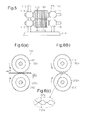
- the roll forming machine disclosed in Patent Document 1 includes, as shown in Fig. 5 , an upper roll 100 and a lower roll 200, which are rotationally supported on a pair of side walls 112, 113 provided on a base 110 via a pair of bearings 114 and a pair of bearings 115.
- the upper roll 100 and the lower roll 200 are formed by laminating disk-like cutters 102, 202 at predetermined intervals.
- cutting parts 102a, 202a project from the peripheral portion of the disk-like cutters 102, 202 at a predetermined pitch.
- the cutting parts 102a, 202a of the rolls 100, 200 mesh with each other. The meshing forms slits in a metal sheet W sandwiched between the rolls 100, 200.
- Patent Document 2 discloses a plastic sheet forming roll apparatus, which includes a base embossing roll driven by a precision control electric motor and a driven embossing roll. A plastic sheet is sandwiched between the base embossing roll and the driven embossing roll so that the plastic sheet is embossed.
- the rotational angle of each of the base embossing roll and the driven embossing roll is measured with a pulse generator, and the precision control electric motor is controlled such that the rotational angles match with each other.
- Patent Document 1 if the gears of the gear mechanism go out of synchronization due to, for example, backlash of the gears, the cutting parts 102a, 202a of the rolls may interfere with each other as shown in Fig. 6(c) , and the cutting parts may possibly be damaged.
- the rolls of Patent Document 1 may be synchronously rotated using the electric motor of Patent Document 2.
- the rolls are controlled to synchronously rotate using, for example, the pulse generator such that the rotational angle of the base embossing roll matches with the rotational angle of the driven embossing roll.
- synchronous control may possibly fail due to disturbance such as electrical noise. In this case, rotational phase deviation may possibly occur.
- the possibility that the cutting parts of the rolls interfere with each other is not eliminated even if the control technology disclosed in Patent Document 2 is applied to the apparatus of Patent Document 1.
- a roll forming machine that includes a pair of processing rolls arranged to face each other.
- the pair of processing rolls each includes cutting parts formed on an outer circumferential portion such that the cutting parts mesh with each other to machine a sheet inserted between the processing rolls.
- the roll forming machine includes interference preventing means that has a pair of dummy rotating bodies arranged on rotary shafts of the pair of processing rolls. Each dummy rotating body includes dummy cutting parts the number of which is equal to the number of the cutting parts of each processing roll.
- the interference preventing means prevents interference between the cutting parts of the processing rolls based on rotational phase deviation that simultaneously occurs between the dummy rotating bodies.
- the interference preventing means preferably sets a first clearance between the dummy cutting parts of the dummy rotating bodies to be smaller than a second clearance between the cutting parts of the processing rolls.
- the interference preventing means preferably causes interference to occur between the dummy cutting parts of the dummy rotating bodies.
- the thickness of the dummy cutting parts is preferably set greater than the thickness of the cutting parts. In this case, damage on the dummy cutting parts when the dummy cutting parts interfere with each other is less than the case in which the thickness is set smaller.
- the dummy cutting parts are preferably set harder than the cutting parts. In this case, damage on the dummy cutting parts when the dummy cutting parts interfere with each other is reduced as compared to a case in which the dummy cutting parts are not set hard.
- the interference preventing means includes a clearance detecting unit, which detects a first clearance between the dummy cutting parts of the dummy rotating bodies, and a controller, which stops a drive source that drives the rotary shafts when the first clearance detected by the clearance detecting unit becomes less than a threshold value.
- the controller stops the driving source of the rotary shafts. This prevents the cutting parts of the processing rolls from interfering with each other, thus preventing damage on the cutting parts.
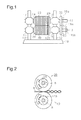
- the roll forming machine includes a base 10, a pair of side walls 12, 13, which extends from the base 10, a first rotary shaft 16, a second rotary shaft 18, a first processing roll 20, which is secured to the first rotary shaft 16, and a second processing roll 40, which is secured to the second rotary shaft 18 to face the first processing roll 20.
- the first rotary shaft 16 is rotationally supported on the side walls 12, 13 by a pair of bearings 14.
- the second rotary shaft 18 is rotationally supported on the side walls 12, 13 by a pair of bearings 15.
- the first rotary shaft 16 and the second rotary shaft 18 are arranged parallel with each other.
- Gears 16a, 18a which mesh with each other, are secured to the right ends of the first rotary shaft 16 and the second rotary shaft 18.
- a sprocket 18b is further secured to the right end of the second rotary shaft 18.
- the sprocket 18b is rotated by a non-illustrated electric motor via a non-illustrated endless chain looped over the sprocket 18b.
- the gears 16a, 18a rotate the first rotary shaft 16 in synchronization with the second rotary shaft 18 at the same speed.
- first processing roll 20 and the second processing roll 40 have the same structure, only the structure and peripheral members of the first processing roll 20 will be described.
- the corresponding structure and peripheral members of the second processing roll 40 will be given reference numbers obtained by adding 100 to the reference numbers of the structure and peripheral members of the first processing roll 20, and detailed explanation is omitted.
- the first processing roll 20 includes a predetermined number of ring-like cutting blades 22 and a metal cylindrical retainer 29.
- the cutting blades 22 are fitted and secured to the outer circumference of the retainer 29 in a laminated state.
- the retainer 29 is secured to the first rotary shaft 16 by a known method (for example, key coupling).
- the cutting blades 22 are formed of hard metal such as stainless-steel.
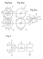
- Protruding cutting parts 26 are formed at a predetermined pitch on the outer circumferential portion of the cutting blades 22 as shown in Fig. 3(a) . Additionally, a recess 27 is formed between adjacent cutting parts 26. Although not shown, any two cutting blades 22 that are adjacent to each other in the axial direction of the first rotary shaft 16 are arranged such that the cutting parts 26 are displaced by half the predetermined pitch.
- the cutting parts 26 of the cutting blades 22 of the first processing roll 20 are arranged to enter recesses 127 of cutting blades 122 of the second processing roll 40 when pressing or roll-forming a workpiece made of a metal plate.
- projections and recesses are continuously formed in a row as shown in Fig. 2 on a metal sheet W by the cutting parts 26 of the cutting blades 22 of the first processing roll 20 and the recesses 127 of the cutting blades 122 of the second processing roll 40, and by cutting parts 126 of the cutting blades 122 of the second processing roll 40 and the recesses 27 of the cutting blades 22 of the first processing roll 20 shown in Fig. 3(a) .
- a pair of dummy rotating bodies 50, 60 is secured to parts of the first rotary shaft 16 and the second rotary shaft 18 located between the gears 16a, 18a and the bearings 14, 15 by a known coupling method such as keys.
- the outer circumferential portions of the dummy rotating bodies 50, 60 are similar to the cutting blades 22, 122 of the first processing roll 20 and the second processing roll 40. That is, in the partially enlarged view of Fig. 3(c) , the solid line defines dummy cutting parts 56, 66 and dummy recesses 57, 67 of the dummy rotating bodies 50, 60, and the broken line defines the cutting parts 26, 126 and the recesses 27, 127 of the cutting blades 22, 122.
- the dummy recesses 57, 67 are the region including the proximal end of the dummy cutting parts 56, 66.
- the number of the dummy cutting parts 56, 66 of the dummy rotating bodies 50, 60 is equal to the number of the cutting parts 26, 126.
- the thickness of the dummy cutting parts 56, 66 is set greater than the thickness of the cutting parts 26, 126 of the first processing roll 20 and the second processing roll 40. Since the thickness of the dummy cutting parts 56, 66 is set greater than the thickness of the cutting parts 26, 126 of the first processing roll 20 and the second processing roll 40, if the dummy cutting parts 56, 66 interfere with each other, damage on the dummy cutting parts 56, 66 is reduced as compared to the case in which the thickness is set smaller.
- the clearance between the distal end of each dummy cutting part 56 and the proximal end of the corresponding dummy cutting part 66 is equal to the clearance between the distal end of each dummy cutting part 66 and the proximal end of the corresponding dummy cutting part 56 (the dummy recess 57).
- the clearances are indicated by C1, and are referred to as a first clearance C1.
- the clearance between the distal end of each cutting part 26 and the proximal end of the corresponding cutting part 126 is equal to the clearance between the distal end of each cutting part 126 and the proximal end of the corresponding cutting part 26 (the recess 27).
- the clearances are indicated by C2, and are referred to as a second clearance C2.
- the first clearance C1 is set smaller than the second clearance C2.
- the second clearance C2 is a gap between the distal end of each cutting part 26 and the proximal end of the corresponding cutting part 126 (the recess 127), which mesh with each other, or a gap between the distal end of each cutting part 126 and the proximal end of the corresponding cutting part 26 (the recess 27), which mesh with each other, while pressing the metal plate (workpiece) in a state where there is no rotational phase deviation between the rolls.
- the first clearance C1 is a gap between the distal end of each dummy cutting part 56 and the proximal end of the corresponding dummy cutting part 66 (the dummy recess 67), or a gap between the distal end of each dummy cutting part 66 and the proximal end of the corresponding dummy cutting part 56 (the dummy recess 57) when the distal end of each cutting part 26 and the proximal end of the corresponding cutting part 126 (the recess 127) mesh with each other with the second clearance C2 in between.
- the first clearance C1 is set smaller than the second clearance C2. If rotational phase deviation occurs between the first processing roll 20 and the second processing roll 40, the dummy cutting parts 56, 66 of the dummy rotating bodies 50, 60 interfere with each other before the cutting parts 26, 126 of the first processing roll 20 and the second processing roll 40 interfere with each other, thus preventing the interference of the cutting parts 26, 126.
- the dimension of the second clearance C2 may be any value as long as it is less than or equal to the thickness of the metal sheet W. If the second clearance C2 is less than the thickness of the metal sheet W, slits are formed by the meshing of the cutting parts 26, 126 as shown in Fig. 2 while the metal sheet W is pressed and extended by the first processing roll 20 and the second processing roll 40. If the second clearance C2 is equal to the thickness of the metal sheet W, the cutting parts 26, 126 form slits as shown in Fig. 2 in accordance with the meshing of the cutting parts 26, 126.
- the present embodiment has the following features.
- the second clearance C2 between the dummy cutting parts 56, 66 of the dummy rotating bodies 50, 60 is set greater than the first clearance C1 between the cutting parts of the first processing roll 20 and the second processing roll 40 so that when rotational phase deviation occurs between the rolls, the dummy cutting parts 56, 66 of the dummy rotating bodies 50, 60 interfere with each other. Consequently, according to the present embodiment, when rotational phase deviation occurs between the processing rolls, the cutting parts of the processing rolls are prevented from interfering with each other, and the cutting parts are prevented from being damaged.
- the second embodiment partially differs from the first embodiment in the electrical configuration, and the hardware structure of the roll forming machine is identical to that of the first embodiment.
- the components of the roll forming machine of the second embodiment are thus provided with the same reference numerals as the corresponding components of the first embodiment, and detailed explanations are omitted.
- the second embodiment includes, to detect the first clearance C1 between each dummy cutting part 56 of the dummy rotating body 50 and the corresponding dummy cutting part 66 of the dummy rotating body 60, an imager 70, which takes images between the dummy cutting parts 56 and the dummy cutting parts 66 at a high speed, an image processor 80, which performs image processing including binarization of each image frame shot by the imager 70 to detect the first clearance C1, and a controller 90, which controls driving and stopping of an electric motor M, which rotates the sprocket 18b in the roll forming machine.
- the gears 16a, 18a and the sprocket 18b shown in Fig. 1 are omitted.
- the imager 70 includes, for example, a CCD camera or a CMOS camera.
- a highspeed shutter of the imager 70 is capable of taking images of the dummy cutting parts 56 and the dummy cutting parts 66, which are rotating.
- the image processor 80 outputs a signal indicating that the first clearance C1 calculated for each image frame has become less than a previously determined threshold value, or that interference may occur.
- the controller 90 stops the electric motor M.
- the imager 70 and the image processor 80 configure a clearance detecting unit.
- the electric motor M is one example of a driving source.
- the present embodiment has the following features.
- the dummy rotating bodies 50, 60 are mounted on the first rotary shaft 16 and the second rotary shaft 18 between the gears 16a, 18a and the bearings 14, 15.
- the positions on the first rotary shaft 16 and the second rotary shaft 18 where the dummy rotating bodies 50, 60 are mounted are not limited.
- the dummy rotating bodies 50, 60 may be provided at positions rightward of the gears 16a, 18a on the first rotary shaft 16 and the second rotary shaft 18 shown in Fig. 1 .
- the left ends of the first rotary shaft 16 and the second rotary shaft 18 shown in Fig. 1 may extend further leftward of the bearings 14, 15, and the dummy rotating bodies 50, 60 may be provided on the extended portions.
- the dummy rotating bodies 50, 60 may be provided on the first rotary shaft 16 and the second rotary shaft 18 between the first and second processing rolls 20, 40 and the bearings 14, 15.
- the hardness of the dummy cutting parts 56, 66 of the dummy rotating bodies 50, 60 is not specified.
- the dummy cutting parts 56, 66 may be harder than the cutting parts 26, 126. If the dummy cutting parts 56, 66 are harder than the cutting parts 26, 126 of the first processing roll 20 and the second processing roll 40, damage on the dummy cutting parts 56, 66 is reduced in a case in which the dummy cutting parts 56, 66 interfere with each other.
- the roll forming machine of the above embodiment machines the metal sheet W.
- the material of the sheet is not limited to metal, but may be plastic or paper.
- the driving source is not limited to an electric motor, but may be anything that rotates the rotary shaft.
- linear motion of a linear driving source (for example, a linear motor) can be converted to rotary motion using a rotation converting mechanism to rotate the rotary shaft.
- the linear driving source may therefore be employed as the driving source.
Landscapes
- Engineering & Computer Science (AREA)
- Mechanical Engineering (AREA)
- Physics & Mathematics (AREA)
- Geometry (AREA)
- Perforating, Stamping-Out Or Severing By Means Other Than Cutting (AREA)
Abstract
Description
- The present invention relates to a roll forming machine.
- The apparatus disclosed in Patent Document 1 is an example of a known roll forming machine. The roll forming machine disclosed in Patent Document 1 includes, as shown in
Fig. 5 , anupper roll 100 and alower roll 200, which are rotationally supported on a pair ofside walls base 110 via a pair ofbearings 114 and a pair ofbearings 115. Theupper roll 100 and thelower roll 200 are formed by laminating disk-like cutters Figs. 6(a) and 6(b) , cuttingparts like cutters cutting parts rolls rolls - Although a method for synchronously rotating the
upper roll 100 and thelower roll 200 is not specifically disclosed in Patent Document 1, torque is typically transmitted between theupper roll 100 and thelower roll 200 via a non-illustrated gear mechanism. - Patent Document 2 discloses a plastic sheet forming roll apparatus, which includes a base embossing roll driven by a precision control electric motor and a driven embossing roll. A plastic sheet is sandwiched between the base embossing roll and the driven embossing roll so that the plastic sheet is embossed. In the apparatus of Patent Document 2, the rotational angle of each of the base embossing roll and the driven embossing roll is measured with a pulse generator, and the precision control electric motor is controlled such that the rotational angles match with each other.
-
- Patent Document 1: Japanese Patent No.
2568285 - Patent Document 2: Japanese Laid-Open Patent Publication No.
10-211650 - In Patent Document 1, if the gears of the gear mechanism go out of synchronization due to, for example, backlash of the gears, the
cutting parts Fig. 6(c) , and the cutting parts may possibly be damaged. - The rolls of Patent Document 1 may be synchronously rotated using the electric motor of Patent Document 2. As described above, in Patent Document 2, the rolls are controlled to synchronously rotate using, for example, the pulse generator such that the rotational angle of the base embossing roll matches with the rotational angle of the driven embossing roll. However, synchronous control may possibly fail due to disturbance such as electrical noise. In this case, rotational phase deviation may possibly occur. Thus, the possibility that the cutting parts of the rolls interfere with each other is not eliminated even if the control technology disclosed in Patent Document 2 is applied to the apparatus of Patent Document 1.
- Accordingly, it is an objective of the present invention to provide a roll forming machine that prevents interference between cutting parts of a pair of processing rolls, and prevents damage on the cutting parts even if rotational phase deviation occurs between the processing rolls.
- To achieve the foregoing objective and in accordance with one aspect of the present invention, a roll forming machine is provided that includes a pair of processing rolls arranged to face each other. The pair of processing rolls each includes cutting parts formed on an outer circumferential portion such that the cutting parts mesh with each other to machine a sheet inserted between the processing rolls. The roll forming machine includes interference preventing means that has a pair of dummy rotating bodies arranged on rotary shafts of the pair of processing rolls. Each dummy rotating body includes dummy cutting parts the number of which is equal to the number of the cutting parts of each processing roll. When rotational phase deviation occurs between the processing rolls, the interference preventing means prevents interference between the cutting parts of the processing rolls based on rotational phase deviation that simultaneously occurs between the dummy rotating bodies.
- In this case, when rotational phase deviation occurs between the pair of processing rolls, the cutting parts of the processing rolls are prevented from interfering each other, thus preventing damage on the cutting parts.
- The interference preventing means preferably sets a first clearance between the dummy cutting parts of the dummy rotating bodies to be smaller than a second clearance between the cutting parts of the processing rolls. When rotational phase deviation occurs, the interference preventing means preferably causes interference to occur between the dummy cutting parts of the dummy rotating bodies.
- In this case, since the dummy cutting parts of the dummy rotating bodies interfere with each other, the cutting parts of the pair of processing rolls are prevented from interfering with each other, thus preventing damage on the cutting parts.
- The thickness of the dummy cutting parts is preferably set greater than the thickness of the cutting parts. In this case, damage on the dummy cutting parts when the dummy cutting parts interfere with each other is less than the case in which the thickness is set smaller.
- The dummy cutting parts are preferably set harder than the cutting parts. In this case, damage on the dummy cutting parts when the dummy cutting parts interfere with each other is reduced as compared to a case in which the dummy cutting parts are not set hard.
- The interference preventing means includes a clearance detecting unit, which detects a first clearance between the dummy cutting parts of the dummy rotating bodies, and a controller, which stops a drive source that drives the rotary shafts when the first clearance detected by the clearance detecting unit becomes less than a threshold value.
- In this case, when the first clearance detected by the clearance detecting unit becomes less than the threshold value, it is determined that rotational phase deviation has occurred between the processing rolls, and the controller stops the driving source of the rotary shafts. This prevents the cutting parts of the processing rolls from interfering with each other, thus preventing damage on the cutting parts.
- According to the present invention, when rotational phase deviation occurs between a pair of processing rolls, cutting parts of the processing rolls are prevented from interfering with each other, thus preventing damage on the cutting parts.
-
-
Fig. 1 is a schematic view illustrating a roll forming machine according to one embodiment; -
Fig. 2 is an explanatory diagram illustrating a state in which a plate is being processed by the roll forming machine; -
Fig. 3(a) is a cross-sectional side view illustrating a first processing roll and a second processing roll; -
Fig. 3(b) is a cross-sectional side view illustrating dummy rotating bodies; -
Fig. 3(c) is a partially enlarged view ofFig. 3(b) ; -
Fig. 4 is a control block diagram of a roll forming machine according to another embodiment; -
Fig. 5 is a schematic view illustrating a conventional roll forming machine; -
Fig. 6(a) is a cross-sectional side view illustrating the upper roll and the lower roll of the conventional roll forming machine; -
Fig. 6(b) is an explanatory diagram illustrating a state in which the cutting parts of the conventional upper and lower rolls interfering with each other; and -
Fig. 6(c) is a partially enlarged view ofFig. 6(b) . - A roll forming machine according to a first embodiment of the present invention will now be described with reference to
Figs. 1 to 3 . - As shown in
Fig. 1 , the roll forming machine includes abase 10, a pair ofside walls base 10, a firstrotary shaft 16, a secondrotary shaft 18, afirst processing roll 20, which is secured to the firstrotary shaft 16, and asecond processing roll 40, which is secured to the secondrotary shaft 18 to face thefirst processing roll 20. The firstrotary shaft 16 is rotationally supported on theside walls bearings 14. The secondrotary shaft 18 is rotationally supported on theside walls bearings 15. The firstrotary shaft 16 and the secondrotary shaft 18 are arranged parallel with each other. - Gears 16a, 18a, which mesh with each other, are secured to the right ends of the first
rotary shaft 16 and the secondrotary shaft 18. Asprocket 18b is further secured to the right end of the secondrotary shaft 18. Thesprocket 18b is rotated by a non-illustrated electric motor via a non-illustrated endless chain looped over thesprocket 18b. When thesprocket 18b is rotated, thegears 16a, 18a rotate the firstrotary shaft 16 in synchronization with the secondrotary shaft 18 at the same speed. - Since the
first processing roll 20 and thesecond processing roll 40 have the same structure, only the structure and peripheral members of thefirst processing roll 20 will be described. The corresponding structure and peripheral members of thesecond processing roll 40 will be given reference numbers obtained by adding 100 to the reference numbers of the structure and peripheral members of thefirst processing roll 20, and detailed explanation is omitted. - As shown in
Figs. 1 and3(a) , thefirst processing roll 20 includes a predetermined number of ring-like cutting blades 22 and a metalcylindrical retainer 29. Thecutting blades 22 are fitted and secured to the outer circumference of theretainer 29 in a laminated state. Theretainer 29 is secured to the firstrotary shaft 16 by a known method (for example, key coupling). Thecutting blades 22 are formed of hard metal such as stainless-steel. - Protruding cutting
parts 26 are formed at a predetermined pitch on the outer circumferential portion of thecutting blades 22 as shown inFig. 3(a) . Additionally, arecess 27 is formed between adjacent cuttingparts 26. Although not shown, any twocutting blades 22 that are adjacent to each other in the axial direction of the firstrotary shaft 16 are arranged such that the cuttingparts 26 are displaced by half the predetermined pitch. - As shown in
Fig. 3(a) , the cuttingparts 26 of thecutting blades 22 of thefirst processing roll 20 are arranged to enterrecesses 127 of cuttingblades 122 of thesecond processing roll 40 when pressing or roll-forming a workpiece made of a metal plate. - In the present embodiment, when a workpiece is fed between the
first processing roll 20 and thesecond processing roll 40 of the roll forming machine and pressed, projections and recesses are continuously formed in a row as shown inFig. 2 on a metal sheet W by the cuttingparts 26 of thecutting blades 22 of thefirst processing roll 20 and therecesses 127 of thecutting blades 122 of thesecond processing roll 40, and by cuttingparts 126 of thecutting blades 122 of thesecond processing roll 40 and therecesses 27 of thecutting blades 22 of thefirst processing roll 20 shown inFig. 3(a) . - In
Fig. 2 , for the purposes of illustration, the contours of thefirst processing roll 20 and thesecond processing roll 40 are substituted by the largest diameter portions of the rotation loci of the cuttingparts - As shown in
Fig. 1 , a pair ofdummy rotating bodies rotary shaft 16 and the secondrotary shaft 18 located between thegears 16a, 18a and thebearings - As shown in
Fig. 3(b) , the outer circumferential portions of thedummy rotating bodies cutting blades first processing roll 20 and thesecond processing roll 40. That is, in the partially enlarged view ofFig. 3(c) , the solid line definesdummy cutting parts dummy rotating bodies parts recesses cutting blades dummy cutting parts dummy cutting parts dummy rotating bodies parts dummy cutting parts parts first processing roll 20 and thesecond processing roll 40. Since the thickness of thedummy cutting parts parts first processing roll 20 and thesecond processing roll 40, if thedummy cutting parts dummy cutting parts - As shown in
Fig. 3(c) , the clearance between the distal end of eachdummy cutting part 56 and the proximal end of the corresponding dummy cutting part 66 (the dummy recess 67) is equal to the clearance between the distal end of eachdummy cutting part 66 and the proximal end of the corresponding dummy cutting part 56 (the dummy recess 57). The clearances are indicated by C1, and are referred to as a first clearance C1. The clearance between the distal end of each cuttingpart 26 and the proximal end of the corresponding cutting part 126 (the recess 127) is equal to the clearance between the distal end of each cuttingpart 126 and the proximal end of the corresponding cutting part 26 (the recess 27). The clearances are indicated by C2, and are referred to as a second clearance C2. The first clearance C1 is set smaller than the second clearance C2. - The second clearance C2 is a gap between the distal end of each cutting
part 26 and the proximal end of the corresponding cutting part 126 (the recess 127), which mesh with each other, or a gap between the distal end of each cuttingpart 126 and the proximal end of the corresponding cutting part 26 (the recess 27), which mesh with each other, while pressing the metal plate (workpiece) in a state where there is no rotational phase deviation between the rolls. Furthermore, the first clearance C1 is a gap between the distal end of eachdummy cutting part 56 and the proximal end of the corresponding dummy cutting part 66 (the dummy recess 67), or a gap between the distal end of eachdummy cutting part 66 and the proximal end of the corresponding dummy cutting part 56 (the dummy recess 57) when the distal end of each cuttingpart 26 and the proximal end of the corresponding cutting part 126 (the recess 127) mesh with each other with the second clearance C2 in between. - In a case in which the
dummy rotating bodies part 26 to interfere with the corresponding cuttingpart 126. - In contrast, according to the present embodiment, the first clearance C1 is set smaller than the second clearance C2. If rotational phase deviation occurs between the
first processing roll 20 and thesecond processing roll 40, thedummy cutting parts dummy rotating bodies parts first processing roll 20 and thesecond processing roll 40 interfere with each other, thus preventing the interference of the cuttingparts - The dimension of the second clearance C2 may be any value as long as it is less than or equal to the thickness of the metal sheet W. If the second clearance C2 is less than the thickness of the metal sheet W, slits are formed by the meshing of the cutting
parts Fig. 2 while the metal sheet W is pressed and extended by thefirst processing roll 20 and thesecond processing roll 40. If the second clearance C2 is equal to the thickness of the metal sheet W, the cuttingparts Fig. 2 in accordance with the meshing of the cuttingparts - Operation of the roll forming machine configured as described above will now be described.
- In a state in which the
first processing roll 20 and thesecond processing roll 40 are rotated in the direction of arrows shown inFig. 2 in accordance with and in synchronization with rotation of thegears 16a, 18a, when the metal sheet W is fed between thefirst processing roll 20 and thesecond processing roll 40, slits are formed in the metal sheet W by the meshing of the cuttingparts Fig. 2 . In this state, if thefirst processing roll 20 and thesecond processing roll 40 go out of synchronization due to backlash of thegears 16a, 18a, and rotational phase deviation occurs between thefirst processing roll 20 and thesecond processing roll 40, thedummy cutting parts dummy rotating bodies parts cutting blades first processing roll 20 and thesecond processing roll 40 interfere with each other, and interference of the cuttingparts gears 16a, 18a go out of synchronization, the cuttingparts parts - The present embodiment has the following features.
-
- (1) In the roll forming machine of the present embodiment, the
first processing roll 20 and the second processing roll 40 (the pair of processing rolls) are arranged to face each other. As the cuttingparts dummy rotating bodies rotary shaft 16 and the secondrotary shaft 18 of thefirst processing roll 20 and thesecond processing roll 40. Thedummy rotating bodies dummy cutting parts dummy rotating bodies first processing roll 20 and thesecond processing roll 40. - According to the interference preventing means, the second clearance C2 between the
dummy cutting parts dummy rotating bodies first processing roll 20 and thesecond processing roll 40 so that when rotational phase deviation occurs between the rolls, thedummy cutting parts dummy rotating bodies -
- (2) According to the roll forming machine of the present embodiment, the thickness of the
dummy cutting parts parts - A second embodiment will now be described with reference to
Fig. 4 . The second embodiment partially differs from the first embodiment in the electrical configuration, and the hardware structure of the roll forming machine is identical to that of the first embodiment. The components of the roll forming machine of the second embodiment are thus provided with the same reference numerals as the corresponding components of the first embodiment, and detailed explanations are omitted. - As shown in
Fig. 4 , the second embodiment includes, to detect the first clearance C1 between eachdummy cutting part 56 of thedummy rotating body 50 and the correspondingdummy cutting part 66 of thedummy rotating body 60, animager 70, which takes images between thedummy cutting parts 56 and thedummy cutting parts 66 at a high speed, animage processor 80, which performs image processing including binarization of each image frame shot by theimager 70 to detect the first clearance C1, and acontroller 90, which controls driving and stopping of an electric motor M, which rotates thesprocket 18b in the roll forming machine. InFig. 4 , for the purposes of illustration, thegears 16a, 18a and thesprocket 18b shown inFig. 1 are omitted. - The
imager 70 includes, for example, a CCD camera or a CMOS camera. A highspeed shutter of theimager 70 is capable of taking images of thedummy cutting parts 56 and thedummy cutting parts 66, which are rotating. Theimage processor 80 outputs a signal indicating that the first clearance C1 calculated for each image frame has become less than a previously determined threshold value, or that interference may occur. Upon receipt of the signal, thecontroller 90 stops the electric motor M. In the present embodiment, theimager 70 and theimage processor 80 configure a clearance detecting unit. The electric motor M is one example of a driving source. - The present embodiment has the following features.
-
- (1) The roll forming machine of the present embodiment includes, as the interference preventing means, the
imager 70, which detects the first clearance C1 between thedummy cutting parts dummy rotating bodies controller 90, which stops the electric motor M (driving source) for driving the secondrotary shaft 18 when the first clearance C1 detected by theimager 70 and theimage processor 80 becomes less than the threshold value. As a result, according to the present embodiment, when the first clearance C1 becomes less than the threshold value, it is determined that rotational phase deviation has occurred between thefirst processing roll 20 and thesecond processing roll 40, and thecontroller 90 stops the electric motor M (driving source), which drives the secondrotary shaft 18. This prevents the cutting parts of thefirst processing roll 20 and thesecond processing roll 40 from interfering with each other, thus preventing the cutting parts from being damaged. - The embodiments of the present invention are not limited to the above illustrated embodiments, but may be modified as follows.
- In the above illustrated embodiments, the
dummy rotating bodies rotary shaft 16 and the secondrotary shaft 18 between thegears 16a, 18a and thebearings rotary shaft 16 and the secondrotary shaft 18 where thedummy rotating bodies dummy rotating bodies gears 16a, 18a on the firstrotary shaft 16 and the secondrotary shaft 18 shown inFig. 1 . Alternatively, the left ends of the firstrotary shaft 16 and the secondrotary shaft 18 shown inFig. 1 may extend further leftward of thebearings dummy rotating bodies - Alternatively, the
dummy rotating bodies rotary shaft 16 and the secondrotary shaft 18 between the first and second processing rolls 20, 40 and thebearings - In the above illustrated embodiments, the hardness of the
dummy cutting parts dummy rotating bodies dummy cutting parts parts dummy cutting parts parts first processing roll 20 and thesecond processing roll 40, damage on thedummy cutting parts dummy cutting parts - In the above illustrated embodiments, the case of synchronization via the gear mechanism is explained. However, the above illustrated invention may be applied to a roll forming machine that employs the technology of synchronous control explained in the conventional device.
- The roll forming machine of the above embodiment machines the metal sheet W. However, the material of the sheet is not limited to metal, but may be plastic or paper.
- The driving source is not limited to an electric motor, but may be anything that rotates the rotary shaft. For example, linear motion of a linear driving source (for example, a linear motor) can be converted to rotary motion using a rotation converting mechanism to rotate the rotary shaft. The linear driving source may therefore be employed as the driving source.
-
- C1, C2...first and second clearances, M...electric motor (driving source),
- 20...first processing roll, 22... cutting blade, 26, 126...cutting parts, 40...second processing roll, 50, 60...dummy rotating bodies, 56, 66...dummy cutting parts, 90...controller, 122...cutting blade, 126...cutting parts.
Claims (5)
- A roll forming machine comprising a pair of processing rolls arranged to face each other, the pair of processing rolls each including cutting parts formed on an outer circumferential portion such that the cutting parts mesh with each other to machine a sheet inserted between the processing rolls,
the roll forming machine being characterized by interference preventing means including a pair of dummy rotating bodies arranged on rotary shafts of the pair of processing rolls, each dummy rotating body including dummy cutting parts the number of which is equal to the number of the cutting parts of each processing roll, wherein, when rotational phase deviation occurs between the processing rolls, the interference preventing means prevents interference between the cutting parts of the processing rolls based on rotational phase deviation that simultaneously occurs between the dummy rotating bodies. - The roll forming machine according to claim 1, wherein the interference preventing means sets a first clearance between the dummy cutting parts of the dummy rotating bodies to be smaller than a second clearance between the cutting parts of the processing rolls, and when rotational phase deviation occurs, the interference preventing means causes interference to occur between the dummy cutting parts of the dummy rotating bodies.
- The roll forming machine according to claim 2, characterized in that the thickness of the dummy cutting parts is set greater than the thickness of the cutting parts.
- The roll forming machine according to claim 2 or 3, characterized in that the dummy cutting parts are set harder than the cutting parts.
- The roll forming machine according to claim 1, characterized in that,
the interference preventing means includes:a clearance detecting unit, which detects a first clearance between the dummy cutting parts of the dummy rotating bodies; anda controller, which stops a drive source that drives the rotary shafts when the first clearance detected by the clearance detecting unit becomes less than a threshold value.
Applications Claiming Priority (2)
| Application Number | Priority Date | Filing Date | Title |
|---|---|---|---|
| JP2012149580A JP5866712B2 (en) | 2012-07-03 | 2012-07-03 | Roll forming equipment |
| PCT/JP2013/067482 WO2014007117A1 (en) | 2012-07-03 | 2013-06-26 | Roll molding device |
Publications (3)
| Publication Number | Publication Date |
|---|---|
| EP2871007A1 true EP2871007A1 (en) | 2015-05-13 |
| EP2871007A4 EP2871007A4 (en) | 2016-04-06 |
| EP2871007B1 EP2871007B1 (en) | 2020-02-19 |
Family
ID=49881874
Family Applications (1)
| Application Number | Title | Priority Date | Filing Date |
|---|---|---|---|
| EP13812725.3A Active EP2871007B1 (en) | 2012-07-03 | 2013-06-26 | Roll molding device |
Country Status (4)
| Country | Link |
|---|---|
| US (1) | US9724855B2 (en) |
| EP (1) | EP2871007B1 (en) |
| JP (1) | JP5866712B2 (en) |
| WO (1) | WO2014007117A1 (en) |
Families Citing this family (3)
| Publication number | Priority date | Publication date | Assignee | Title |
|---|---|---|---|---|
| US11000978B2 (en) * | 2018-06-26 | 2021-05-11 | The Boeing Company | Gap filler roller assembly |
| US10875621B2 (en) * | 2018-06-26 | 2020-12-29 | The Boeing Company | Gap filler roller assembly |
| CN111672943A (en) * | 2020-06-19 | 2020-09-18 | 嘉兴职业技术学院 | Metal foil plate continuous bending forming device |
Family Cites Families (14)
| Publication number | Priority date | Publication date | Assignee | Title |
|---|---|---|---|---|
| US735635A (en) * | 1902-02-15 | 1903-08-04 | Gen Fireproofing Co | Machine for expanding metal. |
| US1864598A (en) * | 1928-11-02 | 1932-06-28 | Kalman Steel Company Inc | Machine for the production of expanded metal |
| GB340333A (en) * | 1929-10-01 | 1931-01-01 | Leon Tirifahy | Improvements in or relating to expanded sheet metal and in the manufacture of same |
| JPS57114314A (en) * | 1980-12-29 | 1982-07-16 | Kawasaki Steel Corp | Method of slitting by rolls without making sheared burr, and slitting roll |
| US5239735A (en) * | 1989-12-28 | 1993-08-31 | Matsushita Electric Industrial Co., Ltd. | Method for manufacturing expanded mesh sheet |
| JP2568285B2 (en) | 1989-12-28 | 1996-12-25 | 松下電器産業株式会社 | Method for manufacturing wrought mesh sheet and apparatus for manufacturing wrought mesh sheet used for the same |
| JPH10211650A (en) | 1997-01-31 | 1998-08-11 | Asahi Chem Ind Co Ltd | Synthetic resin sheet molding roll equipment |
| JP4030618B2 (en) * | 1997-02-06 | 2008-01-09 | 松下電器産業株式会社 | Manufacturing method of stretched mesh sheet |
| CA2288561C (en) * | 1999-11-05 | 2006-10-24 | Michael Surina | Rotary punching apparatus |
| JP2003211225A (en) * | 2002-01-22 | 2003-07-29 | Calsonic Kansei Corp | Corrugated sheet forming stand |
| US7066066B2 (en) * | 2004-03-15 | 2006-06-27 | Teck Cominco Metals Ltd. | Continuous rotary hole punching method and apparatus |
| KR100823670B1 (en) * | 2006-07-19 | 2008-04-18 | 주식회사 동원롤 | Embossing Processing Equipment |
| EP2426243A1 (en) * | 2010-09-01 | 2012-03-07 | Benninger Zell GmbH | Method and device for processing (softening) continuously transported goods |
| EP2468493A1 (en) * | 2010-12-23 | 2012-06-27 | Boegli-Gravures S.A. | Device for embossing films |
-
2012
- 2012-07-03 JP JP2012149580A patent/JP5866712B2/en active Active
-
2013
- 2013-06-26 US US14/403,875 patent/US9724855B2/en active Active
- 2013-06-26 EP EP13812725.3A patent/EP2871007B1/en active Active
- 2013-06-26 WO PCT/JP2013/067482 patent/WO2014007117A1/en not_active Ceased
Also Published As
| Publication number | Publication date |
|---|---|
| WO2014007117A1 (en) | 2014-01-09 |
| US9724855B2 (en) | 2017-08-08 |
| US20150190951A1 (en) | 2015-07-09 |
| EP2871007B1 (en) | 2020-02-19 |
| JP2014012282A (en) | 2014-01-23 |
| EP2871007A4 (en) | 2016-04-06 |
| JP5866712B2 (en) | 2016-02-17 |
Similar Documents
| Publication | Publication Date | Title |
|---|---|---|
| EP2871007B1 (en) | Roll molding device | |
| WO2017134450A1 (en) | Gear inspection method and apparatus | |
| KR20210029314A (en) | Multi-function press roller mechanism with adjustable spacing | |
| EP2388122A2 (en) | Rotary type injection molding machine and an injection molding method | |
| JP5999752B2 (en) | Variable printing machine | |
| KR101456304B1 (en) | Driving device of rotary table | |
| EP2065690B1 (en) | Dynamo-electric machine with a temperature gauge | |
| JP5523544B1 (en) | Rolling mill for outer diameter ring products | |
| TWI772606B (en) | Rotary Lamination Die and Press Device Equipped with Rotary Lamination Die | |
| JP5081013B2 (en) | Biaxial kneading extruder and load torque calculation method in biaxial kneading extruder | |
| JP5280783B2 (en) | Worm rolling device and worm rolling method | |
| KR100682442B1 (en) | Molded phase alignment device in the molded sheet manufacturing apparatus | |
| JP5377114B2 (en) | Indexing table for machine tools | |
| KR100823670B1 (en) | Embossing Processing Equipment | |
| JP2009028866A (en) | Indexing mechanism | |
| JP2017082918A (en) | Rotation limiting device, rotation / linear motion conversion device including the same, electric power steering device, vehicle, and mechanical device | |
| JP5609342B2 (en) | Torque detection device | |
| CN106286716B (en) | Power transmission using inscribed cam and cylindrical pinion | |
| KR102182255B1 (en) | Apparatus for smoothing a toothing system and production process | |
| JP7317598B2 (en) | Spindle device of multi-tasking machine | |
| JP2012172813A (en) | Pitch adjusting mechanism and pitch adjusting method for rotary gear | |
| JP5018734B2 (en) | External tooth forming roller | |
| KR100916076B1 (en) | Cutting device | |
| JP4950560B2 (en) | Belt sleeve material width cutting device | |
| JP4932501B2 (en) | Reduction gear |
Legal Events
| Date | Code | Title | Description |
|---|---|---|---|
| PUAI | Public reference made under article 153(3) epc to a published international application that has entered the european phase |
Free format text: ORIGINAL CODE: 0009012 |
|
| 17P | Request for examination filed |
Effective date: 20141128 |
|
| AK | Designated contracting states |
Kind code of ref document: A1 Designated state(s): AL AT BE BG CH CY CZ DE DK EE ES FI FR GB GR HR HU IE IS IT LI LT LU LV MC MK MT NL NO PL PT RO RS SE SI SK SM TR |
|
| AX | Request for extension of the european patent |
Extension state: BA ME |
|
| DAX | Request for extension of the european patent (deleted) | ||
| RA4 | Supplementary search report drawn up and despatched (corrected) |
Effective date: 20160309 |
|
| RIC1 | Information provided on ipc code assigned before grant |
Ipc: B21D 13/08 20060101AFI20160303BHEP Ipc: B21D 28/12 20060101ALI20160303BHEP Ipc: B21D 31/04 20060101ALI20160303BHEP Ipc: B21D 13/04 20060101ALI20160303BHEP |
|
| STAA | Information on the status of an ep patent application or granted ep patent |
Free format text: STATUS: EXAMINATION IS IN PROGRESS |
|
| 17Q | First examination report despatched |
Effective date: 20170126 |
|
| 17Q | First examination report despatched |
Effective date: 20170203 |
|
| GRAP | Despatch of communication of intention to grant a patent |
Free format text: ORIGINAL CODE: EPIDOSNIGR1 |
|
| STAA | Information on the status of an ep patent application or granted ep patent |
Free format text: STATUS: GRANT OF PATENT IS INTENDED |
|
| INTG | Intention to grant announced |
Effective date: 20191025 |
|
| RIN1 | Information on inventor provided before grant (corrected) |
Inventor name: TAKAMURA, TOMOYUKI Inventor name: HASHIMOTO, KEIJI Inventor name: KINOSHITA, TOMIO Inventor name: KINOSHITA, MANABU |
|
| GRAS | Grant fee paid |
Free format text: ORIGINAL CODE: EPIDOSNIGR3 |
|
| GRAA | (expected) grant |
Free format text: ORIGINAL CODE: 0009210 |
|
| STAA | Information on the status of an ep patent application or granted ep patent |
Free format text: STATUS: THE PATENT HAS BEEN GRANTED |
|
| AK | Designated contracting states |
Kind code of ref document: B1 Designated state(s): AL AT BE BG CH CY CZ DE DK EE ES FI FR GB GR HR HU IE IS IT LI LT LU LV MC MK MT NL NO PL PT RO RS SE SI SK SM TR |
|
| REG | Reference to a national code |
Ref country code: GB Ref legal event code: FG4D |
|
| REG | Reference to a national code |
Ref country code: CH Ref legal event code: EP |
|
| REG | Reference to a national code |
Ref country code: DE Ref legal event code: R096 Ref document number: 602013065975 Country of ref document: DE |
|
| REG | Reference to a national code |
Ref country code: AT Ref legal event code: REF Ref document number: 1234352 Country of ref document: AT Kind code of ref document: T Effective date: 20200315 |
|
| REG | Reference to a national code |
Ref country code: IE Ref legal event code: FG4D |
|
| REG | Reference to a national code |
Ref country code: NL Ref legal event code: MP Effective date: 20200219 |
|
| PG25 | Lapsed in a contracting state [announced via postgrant information from national office to epo] |
Ref country code: FI Free format text: LAPSE BECAUSE OF FAILURE TO SUBMIT A TRANSLATION OF THE DESCRIPTION OR TO PAY THE FEE WITHIN THE PRESCRIBED TIME-LIMIT Effective date: 20200219 Ref country code: NO Free format text: LAPSE BECAUSE OF FAILURE TO SUBMIT A TRANSLATION OF THE DESCRIPTION OR TO PAY THE FEE WITHIN THE PRESCRIBED TIME-LIMIT Effective date: 20200519 Ref country code: RS Free format text: LAPSE BECAUSE OF FAILURE TO SUBMIT A TRANSLATION OF THE DESCRIPTION OR TO PAY THE FEE WITHIN THE PRESCRIBED TIME-LIMIT Effective date: 20200219 |
|
| REG | Reference to a national code |
Ref country code: LT Ref legal event code: MG4D |
|
| PG25 | Lapsed in a contracting state [announced via postgrant information from national office to epo] |
Ref country code: BG Free format text: LAPSE BECAUSE OF FAILURE TO SUBMIT A TRANSLATION OF THE DESCRIPTION OR TO PAY THE FEE WITHIN THE PRESCRIBED TIME-LIMIT Effective date: 20200519 Ref country code: GR Free format text: LAPSE BECAUSE OF FAILURE TO SUBMIT A TRANSLATION OF THE DESCRIPTION OR TO PAY THE FEE WITHIN THE PRESCRIBED TIME-LIMIT Effective date: 20200520 Ref country code: LV Free format text: LAPSE BECAUSE OF FAILURE TO SUBMIT A TRANSLATION OF THE DESCRIPTION OR TO PAY THE FEE WITHIN THE PRESCRIBED TIME-LIMIT Effective date: 20200219 Ref country code: SE Free format text: LAPSE BECAUSE OF FAILURE TO SUBMIT A TRANSLATION OF THE DESCRIPTION OR TO PAY THE FEE WITHIN THE PRESCRIBED TIME-LIMIT Effective date: 20200219 Ref country code: IS Free format text: LAPSE BECAUSE OF FAILURE TO SUBMIT A TRANSLATION OF THE DESCRIPTION OR TO PAY THE FEE WITHIN THE PRESCRIBED TIME-LIMIT Effective date: 20200619 Ref country code: HR Free format text: LAPSE BECAUSE OF FAILURE TO SUBMIT A TRANSLATION OF THE DESCRIPTION OR TO PAY THE FEE WITHIN THE PRESCRIBED TIME-LIMIT Effective date: 20200219 |
|
| PG25 | Lapsed in a contracting state [announced via postgrant information from national office to epo] |
Ref country code: NL Free format text: LAPSE BECAUSE OF FAILURE TO SUBMIT A TRANSLATION OF THE DESCRIPTION OR TO PAY THE FEE WITHIN THE PRESCRIBED TIME-LIMIT Effective date: 20200219 |
|
| PG25 | Lapsed in a contracting state [announced via postgrant information from national office to epo] |
Ref country code: CZ Free format text: LAPSE BECAUSE OF FAILURE TO SUBMIT A TRANSLATION OF THE DESCRIPTION OR TO PAY THE FEE WITHIN THE PRESCRIBED TIME-LIMIT Effective date: 20200219 Ref country code: PT Free format text: LAPSE BECAUSE OF FAILURE TO SUBMIT A TRANSLATION OF THE DESCRIPTION OR TO PAY THE FEE WITHIN THE PRESCRIBED TIME-LIMIT Effective date: 20200712 Ref country code: DK Free format text: LAPSE BECAUSE OF FAILURE TO SUBMIT A TRANSLATION OF THE DESCRIPTION OR TO PAY THE FEE WITHIN THE PRESCRIBED TIME-LIMIT Effective date: 20200219 Ref country code: LT Free format text: LAPSE BECAUSE OF FAILURE TO SUBMIT A TRANSLATION OF THE DESCRIPTION OR TO PAY THE FEE WITHIN THE PRESCRIBED TIME-LIMIT Effective date: 20200219 Ref country code: SM Free format text: LAPSE BECAUSE OF FAILURE TO SUBMIT A TRANSLATION OF THE DESCRIPTION OR TO PAY THE FEE WITHIN THE PRESCRIBED TIME-LIMIT Effective date: 20200219 Ref country code: EE Free format text: LAPSE BECAUSE OF FAILURE TO SUBMIT A TRANSLATION OF THE DESCRIPTION OR TO PAY THE FEE WITHIN THE PRESCRIBED TIME-LIMIT Effective date: 20200219 Ref country code: SK Free format text: LAPSE BECAUSE OF FAILURE TO SUBMIT A TRANSLATION OF THE DESCRIPTION OR TO PAY THE FEE WITHIN THE PRESCRIBED TIME-LIMIT Effective date: 20200219 Ref country code: RO Free format text: LAPSE BECAUSE OF FAILURE TO SUBMIT A TRANSLATION OF THE DESCRIPTION OR TO PAY THE FEE WITHIN THE PRESCRIBED TIME-LIMIT Effective date: 20200219 Ref country code: ES Free format text: LAPSE BECAUSE OF FAILURE TO SUBMIT A TRANSLATION OF THE DESCRIPTION OR TO PAY THE FEE WITHIN THE PRESCRIBED TIME-LIMIT Effective date: 20200219 |
|
| REG | Reference to a national code |
Ref country code: AT Ref legal event code: MK05 Ref document number: 1234352 Country of ref document: AT Kind code of ref document: T Effective date: 20200219 |
|
| REG | Reference to a national code |
Ref country code: DE Ref legal event code: R097 Ref document number: 602013065975 Country of ref document: DE |
|
| PLBE | No opposition filed within time limit |
Free format text: ORIGINAL CODE: 0009261 |
|
| STAA | Information on the status of an ep patent application or granted ep patent |
Free format text: STATUS: NO OPPOSITION FILED WITHIN TIME LIMIT |
|
| 26N | No opposition filed |
Effective date: 20201120 |
|
| PG25 | Lapsed in a contracting state [announced via postgrant information from national office to epo] |
Ref country code: AT Free format text: LAPSE BECAUSE OF FAILURE TO SUBMIT A TRANSLATION OF THE DESCRIPTION OR TO PAY THE FEE WITHIN THE PRESCRIBED TIME-LIMIT Effective date: 20200219 Ref country code: IT Free format text: LAPSE BECAUSE OF FAILURE TO SUBMIT A TRANSLATION OF THE DESCRIPTION OR TO PAY THE FEE WITHIN THE PRESCRIBED TIME-LIMIT Effective date: 20200219 Ref country code: MC Free format text: LAPSE BECAUSE OF FAILURE TO SUBMIT A TRANSLATION OF THE DESCRIPTION OR TO PAY THE FEE WITHIN THE PRESCRIBED TIME-LIMIT Effective date: 20200219 |
|
| REG | Reference to a national code |
Ref country code: CH Ref legal event code: PL |
|
| PG25 | Lapsed in a contracting state [announced via postgrant information from national office to epo] |
Ref country code: PL Free format text: LAPSE BECAUSE OF FAILURE TO SUBMIT A TRANSLATION OF THE DESCRIPTION OR TO PAY THE FEE WITHIN THE PRESCRIBED TIME-LIMIT Effective date: 20200219 Ref country code: SI Free format text: LAPSE BECAUSE OF FAILURE TO SUBMIT A TRANSLATION OF THE DESCRIPTION OR TO PAY THE FEE WITHIN THE PRESCRIBED TIME-LIMIT Effective date: 20200219 |
|
| PG25 | Lapsed in a contracting state [announced via postgrant information from national office to epo] |
Ref country code: LU Free format text: LAPSE BECAUSE OF NON-PAYMENT OF DUE FEES Effective date: 20200626 |
|
| REG | Reference to a national code |
Ref country code: BE Ref legal event code: MM Effective date: 20200630 |
|
| PG25 | Lapsed in a contracting state [announced via postgrant information from national office to epo] |
Ref country code: IE Free format text: LAPSE BECAUSE OF NON-PAYMENT OF DUE FEES Effective date: 20200626 Ref country code: LI Free format text: LAPSE BECAUSE OF NON-PAYMENT OF DUE FEES Effective date: 20200630 Ref country code: CH Free format text: LAPSE BECAUSE OF NON-PAYMENT OF DUE FEES Effective date: 20200630 |
|
| PG25 | Lapsed in a contracting state [announced via postgrant information from national office to epo] |
Ref country code: BE Free format text: LAPSE BECAUSE OF NON-PAYMENT OF DUE FEES Effective date: 20200630 |
|
| PG25 | Lapsed in a contracting state [announced via postgrant information from national office to epo] |
Ref country code: TR Free format text: LAPSE BECAUSE OF FAILURE TO SUBMIT A TRANSLATION OF THE DESCRIPTION OR TO PAY THE FEE WITHIN THE PRESCRIBED TIME-LIMIT Effective date: 20200219 Ref country code: MT Free format text: LAPSE BECAUSE OF FAILURE TO SUBMIT A TRANSLATION OF THE DESCRIPTION OR TO PAY THE FEE WITHIN THE PRESCRIBED TIME-LIMIT Effective date: 20200219 Ref country code: CY Free format text: LAPSE BECAUSE OF FAILURE TO SUBMIT A TRANSLATION OF THE DESCRIPTION OR TO PAY THE FEE WITHIN THE PRESCRIBED TIME-LIMIT Effective date: 20200219 |
|
| PG25 | Lapsed in a contracting state [announced via postgrant information from national office to epo] |
Ref country code: MK Free format text: LAPSE BECAUSE OF FAILURE TO SUBMIT A TRANSLATION OF THE DESCRIPTION OR TO PAY THE FEE WITHIN THE PRESCRIBED TIME-LIMIT Effective date: 20200219 Ref country code: AL Free format text: LAPSE BECAUSE OF FAILURE TO SUBMIT A TRANSLATION OF THE DESCRIPTION OR TO PAY THE FEE WITHIN THE PRESCRIBED TIME-LIMIT Effective date: 20200219 |
|
| PGFP | Annual fee paid to national office [announced via postgrant information from national office to epo] |
Ref country code: DE Payment date: 20250429 Year of fee payment: 13 |
|
| PGFP | Annual fee paid to national office [announced via postgrant information from national office to epo] |
Ref country code: GB Payment date: 20250508 Year of fee payment: 13 |
|
| PGFP | Annual fee paid to national office [announced via postgrant information from national office to epo] |
Ref country code: FR Payment date: 20250508 Year of fee payment: 13 |