EP2870323B1 - Dispositif de joint d'etancheite de palier de turbomachine avec deux joints elastiques - Google Patents
Dispositif de joint d'etancheite de palier de turbomachine avec deux joints elastiques Download PDFInfo
- Publication number
- EP2870323B1 EP2870323B1 EP13744687.8A EP13744687A EP2870323B1 EP 2870323 B1 EP2870323 B1 EP 2870323B1 EP 13744687 A EP13744687 A EP 13744687A EP 2870323 B1 EP2870323 B1 EP 2870323B1
- Authority
- EP
- European Patent Office
- Prior art keywords
- turbomachine
- bearing
- sleeve
- seal
- gasket
- Prior art date
- Legal status (The legal status is an assumption and is not a legal conclusion. Google has not performed a legal analysis and makes no representation as to the accuracy of the status listed.)
- Active
Links
Images
Classifications
-
- F—MECHANICAL ENGINEERING; LIGHTING; HEATING; WEAPONS; BLASTING
- F01—MACHINES OR ENGINES IN GENERAL; ENGINE PLANTS IN GENERAL; STEAM ENGINES
- F01D—NON-POSITIVE DISPLACEMENT MACHINES OR ENGINES, e.g. STEAM TURBINES
- F01D11/00—Preventing or minimising internal leakage of working-fluid, e.g. between stages
- F01D11/003—Preventing or minimising internal leakage of working-fluid, e.g. between stages by packing rings; Mechanical seals
-
- F—MECHANICAL ENGINEERING; LIGHTING; HEATING; WEAPONS; BLASTING
- F01—MACHINES OR ENGINES IN GENERAL; ENGINE PLANTS IN GENERAL; STEAM ENGINES
- F01D—NON-POSITIVE DISPLACEMENT MACHINES OR ENGINES, e.g. STEAM TURBINES
- F01D25/00—Component parts, details, or accessories, not provided for in, or of interest apart from, other groups
- F01D25/16—Arrangement of bearings; Supporting or mounting bearings in casings
-
- F—MECHANICAL ENGINEERING; LIGHTING; HEATING; WEAPONS; BLASTING
- F01—MACHINES OR ENGINES IN GENERAL; ENGINE PLANTS IN GENERAL; STEAM ENGINES
- F01D—NON-POSITIVE DISPLACEMENT MACHINES OR ENGINES, e.g. STEAM TURBINES
- F01D25/00—Component parts, details, or accessories, not provided for in, or of interest apart from, other groups
- F01D25/18—Lubricating arrangements
- F01D25/183—Sealing means
-
- F—MECHANICAL ENGINEERING; LIGHTING; HEATING; WEAPONS; BLASTING
- F16—ENGINEERING ELEMENTS AND UNITS; GENERAL MEASURES FOR PRODUCING AND MAINTAINING EFFECTIVE FUNCTIONING OF MACHINES OR INSTALLATIONS; THERMAL INSULATION IN GENERAL
- F16J—PISTONS; CYLINDERS; SEALINGS
- F16J15/00—Sealings
- F16J15/16—Sealings between relatively-moving surfaces
- F16J15/18—Sealings between relatively-moving surfaces with stuffing-boxes for elastic or plastic packings
- F16J15/24—Sealings between relatively-moving surfaces with stuffing-boxes for elastic or plastic packings with radially or tangentially compressed packing
-
- F—MECHANICAL ENGINEERING; LIGHTING; HEATING; WEAPONS; BLASTING
- F16—ENGINEERING ELEMENTS AND UNITS; GENERAL MEASURES FOR PRODUCING AND MAINTAINING EFFECTIVE FUNCTIONING OF MACHINES OR INSTALLATIONS; THERMAL INSULATION IN GENERAL
- F16J—PISTONS; CYLINDERS; SEALINGS
- F16J15/00—Sealings
- F16J15/16—Sealings between relatively-moving surfaces
- F16J15/32—Sealings between relatively-moving surfaces with elastic sealings, e.g. O-rings
- F16J15/3268—Mounting of sealing rings
- F16J15/3276—Mounting of sealing rings with additional static sealing between the sealing, or its casing or support, and the surface on which it is mounted
-
- F—MECHANICAL ENGINEERING; LIGHTING; HEATING; WEAPONS; BLASTING
- F05—INDEXING SCHEMES RELATING TO ENGINES OR PUMPS IN VARIOUS SUBCLASSES OF CLASSES F01-F04
- F05D—INDEXING SCHEME FOR ASPECTS RELATING TO NON-POSITIVE-DISPLACEMENT MACHINES OR ENGINES, GAS-TURBINES OR JET-PROPULSION PLANTS
- F05D2300/00—Materials; Properties thereof
- F05D2300/20—Oxide or non-oxide ceramics
- F05D2300/22—Non-oxide ceramics
- F05D2300/224—Carbon, e.g. graphite
Definitions
- the present invention relates to the field of turbomachines. It relates to a turbomachine bearing seal device, and the turbomachine comprising such a device.
- the invention applies to all types of land or aeronautical turbomachines, and in particular to aircraft turbomachines such as turbojets and turboprops. More preferentially, the invention applies to a double-body and dual-flow turbojet engine.
- a turbomachine bearing supporting a rotating shaft inside a fixed casing comprises a bearing disposed in a chamber where its lubrication is ensured.
- any migration of oil must be avoided to certain compartments of the turbomachine and the seal must thus be ensured at the separation between the bearing chamber containing oil and a neighboring air chamber which must be maintained oil free.
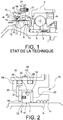
- the figure 1 illustrates an example of use of such a segmented seal, also called segmented radial seal (JRS), comprising in particular a static sealing ring consisting of carbon segments.
- a shaft 1 is rotatably supported by a bearing, carried by a housing 2, having a bearing 3.
- a sleeve 4 secured in rotation to the shaft 1 is interposed between the bearing 3 and the shaft 1, according to provisions known per se in the application to turbomachines.
- the bearing 3 is included in an enclosure 5 where there is both air and oil for the lubrication of the bearing 3 provided in a manner known per se.
- the shaft 1 is surrounded by a chamber 6 known as air and must remain oil-free because any rise of oil in some compartments of the turbomachine would be detrimental to a good operation.
- a sealing device 10 is thus disposed between the shaft 1 and the casing 2 at the separation between the oil chamber 5 and the air chamber 6.
- the sealing device 10 comprises a static sealing ring 7, consisting of carbon segments which are held together by means of a circumferential spring 22, this spring 22 clamping the carbon segments against the sleeve 4.
- Static sealing ring 7 is associated with a rotating surface 8, which may include grooves 12 to create lift.
- This rotating surface 8 is extended by a cylindrical surface 9, in connection with a labyrinth oil discharge system 11 to prevent the arrival of oil particles on the carbon segments.
- the static sealing ring 7 is held in a metal support casing 14 (or support 14) by the circumferential spring 22 and axial springs 21, supported on a ring 18 which is held in the support 14 by a gasket. stop 20.
- the support 14 is centered without tightening by means of an O-ring 19 placed between the support 14 and a housing element 24 acting as a cover and thus allowing the fixing of the static part of the seal device 10 on the casing 2 of the turbomachine.
- Dynamic sealing is performed between the respective cooperating cylindrical faces 16 and 17 of the carbon segments 7 and the rotating surface 8.
- the static seal is formed between the carbon segments 7 and the static face 23 of the support 14, located at level of the labyrinth oil discharge ring 11, to prevent radial leakage.
- the static seal ring 7 must be mounted so as to keep in operation a high concentricity with respect to the rotor and a perpendicularity with respect to the static face 23.
- the object of the invention is to remedy at least partially the needs mentioned above and the drawbacks relating to the embodiments of the prior art.
- the turbomachine is characterized in that the support casing comprises a second groove housing a second elastic seal for centering the support casing on the casing element, in that the rotating surface of the sleeve is extended by a surface cylindrical, and in that the support casing comprises a labyrinth oil discharge system in relation to the cylindrical surface.
- the solution proposed by the invention can make it possible to avoid the various disadvantages of the known solutions of the prior art while ensuring the desired sealing between an air chamber and an oil chamber. Thanks to the invention, it may for example be possible to overcome the difficulties relating to the radial clearance opening due to differences between the materials of the components of the turbomachine in terms of expansion.
- the centering of the support casing on the casing element by means of two elastic seals can make it possible to damp the vibrations of the casing, and thus to reduce the axial wear of the carbon segments of the seal. segmented sealing.
- the turbomachine according to the invention may further comprise one or more of the following characteristics taken separately or in any possible technical combination.
- the first and second grooves may be identical, having in particular the same dimensions and the same shape.
- the first and second grooves are advantageously formed on the part of the support casing located opposite the casing element.
- the support casing may comprise more than two grooves each housing an elastic seal for centering the support casing on the casing element, in particular at least three, at least four, or even five grooves each housing an elastic seal.
- the first and second elastic seals may have the same dimensions.
- the first and second elastic joints may have the same diameter.
- the first and second elastic seals advantageously come into contact with the housing element.
- the first and second elastic seals can be of any type, including O-rings.
- the first and second elastic joints may be selected so that the maximum radial clearance opening between the crankcase element and the elastic joints, in operation of the turbomachine, is within the range of acceptable minimum and maximum values due to design constraints for crushing an elastic seal, particularly an O-ring.
- the first and second elastic seals can be installed when mounting the seal device with the maximum acceptable crush value.
- the first and second grooves may be spaced from each other by a greater distance, less than or equal to the width of at least one of the first and second grooves, in particular the width of each of the first and second grooves.
- the spacing between the first and second grooves can be maximum to make the centering of the support casing on the optimal casing element.
- the first and second elastic joints may be made of any type of elastic material, especially an elastomeric material.
- the segmented seal may comprise a sealing ring having an assembly of one or more carbon segments, which can be held together by a circumferential spring and / or supported on the support casing by one or more axial springs. support on a stop joint, especially a stop ring (JRS type or face seals).
- the turbomachine bearing is similar to that described with reference to the figure 1 .
- the bearing comprises a bearing 3 mounted between a sleeve 4 integral with a shaft 1 and a housing 2, the sleeve 4 having a rotating surface 8 and the housing 2 having a housing element 24 acting as a cover for the device seal 10.
- the seal device 10 is able to separate an oil chamber 5 of the bearing 3 and an air chamber 6 of the turbomachine.
- the sealing device 10 represented on the figure 2 differs from that shown on the figure 1 in that it comprises a support casing 14 comprising two housings 25 each housing an elastic seal 19, according to the invention.
- the seal device 10 comprises a segmented seal 7, consisting of a static seal ring of carbon segments held together by a circumferential spring 22, which is mounted in association with the rotating surface. 8 of the sleeve 4 to ensure the main seal of the seal device 10.
- the latter also comprises a support casing 14 (or support 14) for holding the segmented seal 7, the support 14 being mounted between the sleeve 4 and the housing element 24.
- the support 14 comprises first and second grooves 25 respectively housing first and second elastic joints 19 allow centering of the support 14 on the housing element 24.
- first and second grooves 25 may be identical and the first and second elastic joints 19 may be O-rings of the same diameter, made of an elastomeric material.
- the two O-rings 19 can be separated from each other. other as much as possible.
- the distance D between the first and second grooves 25 may be as large as possible, being in particular greater than or equal to the width L of the first and second grooves 25.
- the centering of the support 14 on the housing element 24 can be facilitated, and even be performed cold, the support 14 may for example be mounted in its bore according to the adjustment H7g6 defined by the ISO system of adjustments.
- the support 14 could comprise more than two grooves 25 each associated with an elastic seal 19.
- the grooves 25 and / or the elastic joints 19 may or may not be identical.
Landscapes
- Engineering & Computer Science (AREA)
- General Engineering & Computer Science (AREA)
- Mechanical Engineering (AREA)
- Gasket Seals (AREA)
- Sealing Using Fluids, Sealing Without Contact, And Removal Of Oil (AREA)
- Turbine Rotor Nozzle Sealing (AREA)
- Support Of The Bearing (AREA)
- Sealing Devices (AREA)
- Rolling Contact Bearings (AREA)
Description
- La présente invention se rapporte au domaine des turbomachines. Elle concerne un dispositif de joint d'étanchéité de palier de turbomachine, ainsi que la turbomachine comportant un tel dispositif.
- L'invention s'applique à tout type de turbomachines terrestres ou aéronautiques, et notamment aux turbomachines d'aéronef telles que les turboréacteurs et les turbopropulseurs. Plus préférentiellement, l'invention s'applique à un turboréacteur double corps et double flux.
- De façon classique, un palier de turbomachine supportant un arbre tournant à l'intérieur d'un carter fixe comporte un roulement disposé dans une enceinte où sa lubrification est assurée. Toutefois, toute migration d'huile doit être évitée vers certains compartiments de la turbomachine et l'étanchéité doit ainsi être assurée à la séparation entre l'enceinte de palier contenant de l'huile et une enceinte voisine à l'air qui doit être maintenue exempte d'huile.
- Plusieurs solutions ont déjà été proposées dans ce but, utilisant par exemple des joints d'étanchéité segmentés en carbone associés à diverses modalités de mise en place.
- La
figure 1 illustre un exemple d'utilisation d'un tel joint d'étanchéité segmenté, appelé encore joint radial segmenté (JRS), comportant en particulier un anneau d'étanchéité statique constitué de segments de carbone. Sur cette figure, un arbre 1 est supporté en rotation par un palier, porté par un carter 2, comportant un roulement 3. Un manchon 4 solidarisé en rotation à l'arbre 1 est interposé entre le roulement 3 et l'arbre 1, suivant des dispositions connues en soi dans l'application aux turbomachines. Le roulement 3 est compris dans une enceinte 5 où sont présents à la fois de l'air et de l'huile en vue de la lubrification du roulement 3 assurée de manière connue en soi. - Au-delà du palier de support, l'arbre 1 est entouré d'une enceinte 6 dite à air et qui doit rester exempte d'huile car toute remontée d'huile dans certains compartiments de la turbomachine serait préjudiciable à un bon fonctionnement. Un dispositif d'étanchéité 10 est ainsi disposé entre l'arbre 1 et le carter 2 à la séparation entre l'enceinte à huile 5 et l'enceinte à air 6.
- Le dispositif d'étanchéité 10 comporte un anneau d'étanchéité statique 7, constitué de segments de carbone qui sont maintenus ensemble à l'aide d'un ressort circonférentiel 22, ce ressort 22 serrant les segments de carbone contre le manchon 4. L'anneau d'étanchéité statique 7 est associé à une surface tournante 8, pouvant comporter des rainures 12 pour créer de la portance. Cette surface tournante 8 se prolonge par une surface cylindrique 9, en relation avec un système de refoulement d'huile à labyrinthe 11 pour éviter l'arrivée de particules d'huile sur les segments de carbone.
- L'anneau d'étanchéité statique 7 est maintenu dans une enveloppe de support 14 métallique (ou support 14) par le ressort circonférentiel 22 et des ressorts axiaux 21, appuyés sur un anneau 18 qui est maintenu dans le support 14 par un joint d'arrêt 20. Le support 14 est centré sans serrage au moyen d'un joint torique 19 placé entre le support 14 et un élément de carter 24 faisant office de couvercle et permettant ainsi la fixation de la partie statique du dispositif de joint d'étanchéité 10 sur le carter 2 de la turbomachine.
- L'étanchéité dynamique est réalisée entre les faces cylindriques coopérantes respectives 16 et 17 des segments de carbone 7 et de la surface tournante 8. L'étanchéité statique est réalisée entre les segments de carbone 7 et la face statique 23 du support 14, située au niveau de l'anneau de refoulement d'huile à labyrinthe 11, pour éviter toute fuite radiale. Aussi, pour parvenir à assurer une étanchéité dynamique et une étanchéité statique satisfaisantes, l'anneau d'étanchéité statique 7 doit être monté de sorte à conserver en fonctionnement une concentricité élevée par rapport au rotor et une perpendicularité par rapport à la face statique 23.
- Cependant, les montages connus de l'art antérieur, comme celui décrit en référence à la
figure 1 , pour un joint d'étanchéité segmenté sont généralement insuffisants pour répondre à ces besoins, notamment pour les applications visées par la présente invention. En particulier, l'étanchéité peut être difficile à réaliser en fonctionnement étant donné que le matériau choisi pour le support 14, à savoir en général de l'acier du fait de contraintes tribologiques, se dilate sensiblement moitié moins que celui choisi pour l'élément de carter 24, à savoir en général de l'aluminium pour les moteurs les plus récents. De la sorte, il peut arriver qu'un mouvement de rotule se crée autour du joint torique 19 qui, en détériorant le contact entre les surfaces frottantes, augmente l'ouverture de jeu radial et diminuant l'efficacité de l'étanchéité ainsi réalisée. - Par ailleurs, la demande internationale
WO 2012/022550 A2 décrit un autre exemple de dispositif d'étanchéité, placé entre deux parties d'un turbocompresseur, permettant de réaliser une séparation entre deux enceintes sous des pressions différentes, et la demande de brevetEP 2 410 134 A1 enseigne également l'utilisation d'un dispositif d'étanchéité dans une turbomachine. - Il existe ainsi un besoin pour proposer un nouveau montage d'un joint d'étanchéité segmenté d'un dispositif de joint d'étanchéité de palier de turbomachine, permettant d'améliorer l'étanchéité du dispositif en fonctionnement. Il existe notamment un besoin pour concevoir un montage d'un joint d'étanchéité segmenté qui soit adapté aux contraintes existantes sur le choix des matériaux des constituants d'une turbomachine.
- L'invention a pour but de remédier au moins partiellement aux besoins mentionnés ci-dessus et aux inconvénients relatifs aux réalisations de l'art antérieur.
- L'invention a ainsi pour objet, selon l'un de ses aspects, une turbomachine comportant un dispositif de joint d'étanchéité de palier de turbomachine à deux joints élastiques. Ledit palier comporte un roulement monté entre un manchon solidaire d'un arbre et un carter. Le manchon présente une surface tournante et le carter comporte un élément de carter faisant office de couvercle pour le dispositif de joint d'étanchéité. Le dispositif de joint d'étanchéité est apte à séparer une enceinte à huile du roulement et une enceinte à air de la turbomachine. Il comporte :
- un joint d'étanchéité segmenté, comportant en particulier un ou des segments de carbone, monté en association avec la surface tournante du manchon, pour assurer notamment l'étanchéité principale du dispositif,
- une enveloppe de support pour maintenir le joint d'étanchéité segmenté, montée entre le manchon et l'élément de carter, l'enveloppe de support comportant une première gorge logeant un premier joint élastique pour le centrage de l'enveloppe de support sur l'élément de carter, en particulier pour l'alignement de l'axe de l'enveloppe de support avec l'axe de l'élément de carter.
- La turbomachine est caractérisé en ce que l'enveloppe de support comporte une deuxième gorge logeant un deuxième joint élastique pour le centrage de l'enveloppe de support sur l'élément de carter, en ce que la surface tournante du manchon se prolonge par une surface cylindriqe, et en ce que l'enveloppe de support comporte un système de refoulement d'huile à labyrinthe en relation avec la surface cylindrique.
- La solution proposée par l'invention peut permettre d'éviter les divers inconvénients des solutions connues de l'art antérieur tout en assurant l'étanchéité recherchée entre une enceinte à air et une enceinte à huile. Grâce à l'invention, il peut par exemple être possible de surmonter les difficultés relatives à l'ouverture de jeu radial du fait des différences existantes entre les matériaux des constituants de la turbomachine en termes de dilatation. De plus, le centrage de l'enveloppe de support sur l'élément de carter par l'intermédiaire de deux joints élastiques peut permettre d'amortir les vibrations du carter, et ainsi de réduire l'usure axiale des segments de carbone du joint d'étanchéité segmenté.
- La turbomachine selon l'invention peut en outre comporter l'une ou plusieurs des caractéristiques suivantes prises isolément ou suivant toutes combinaisons techniques possibles.
- Les première et deuxième gorges peuvent être identiques, présentant notamment les mêmes dimensions et la même forme.
- Les première et deuxième gorges sont avantageusement formées sur la partie de l'enveloppe de support située en regard de l'élément de carter.
- L'enveloppe de support peut comporter plus de deux gorges logeant chacune un joint élastique pour le centrage de l'enveloppe de support sur l'élément de carter, notamment au moins trois, au moins quatre, voire cinq gorges logeant chacune un joint élastique.
- Les premier et deuxième joints élastiques peuvent présenter les mêmes dimensions. En particulier, les premier et deuxième joints élastiques peuvent présenter le même diamètre.
- Les premier et deuxième joints élastiques viennent avantageusement au contact de l'élément de carter.
- Les premier et deuxième joints élastiques peuvent être de tout type, étant notamment des joints toriques.
- Les premier et deuxième joints élastiques peuvent être choisis de sorte que l'ouverture de jeu radial maximale entre l'élément de carter et les joints élastiques, en fonctionnement de la turbomachine, soit comprise dans le domaine des valeurs minimale et maximale acceptables du fait de contraintes de conception pour l'écrasement d'un joint élastique, en particulier un joint torique. Les premier et deuxième joints élastiques peuvent être installés lors du montage du dispositif de joint d'étanchéité avec la valeur maximale acceptable d'écrasement.
- Les première et deuxième gorges peuvent être espacées l'une de l'autre d'une distance supérieure, inférieure ou égale à la largeur d'au moins une des première et deuxième gorges, notamment à la largeur de chacune des première et deuxième gorge.
- L'espacement entre les première et deuxième gorges peut être maximal pour rendre le centrage de l'enveloppe de support sur l'élément de carter optimal.
- Les premier et deuxième joints élastiques peuvent être réalisés en tout type de matériau élastique, notamment en un matériau élastomère.
- Le joint d'étanchéité segmenté peut comporter un anneau d'étanchéité comportant un ensemble d'un ou plusieurs segments de carbone, pouvant être maintenus ensemble par un ressort circonférentiel et/ou appuyés sur l'enveloppe de support par un ou des ressorts axiaux en appui sur un joint d'arrêt, notamment un anneau d'arrêt (du type JRS ou joints faciaux).
- L'invention pourra être mieux comprise à la lecture de la description détaillée qui va suivre, d'un exemple de mise en oeuvre non limitatif de celle-ci, ainsi qu'à l'examen des figures, schématiques et partielles, du dessin annexé, sur lequel :
- la
figure 1 représente, selon une vue en coupe par un plan passant par l'axe de rotation de l'arbre, une partie de palier de turbomachine comportant un dispositif de joint d'étanchéité d'enceinte selon l'art antérieur, et - la
figure 2 représente une vue agrandie d'un palier de turbomachine semblable à celui de lafigure 1 , comportant toutefois un dispositif de joint d'étanchéité d'une turbomachine selon l'invention. - Dans l'ensemble de ces figures, des références identiques peuvent désigner des éléments identiques ou analogues.
- De plus, les différentes parties représentées sur les figures ne le sont pas nécessairement selon une échelle uniforme, pour rendre les figures plus lisibles.
- Il va être décrit ci-après, en référence à la
figure 2 , un exemple de réalisation de l'invention se rapportant à un dispositif de joint d'étanchéité 10 de palier de turbomachine. - Le palier de turbomachine est semblable à celui décrit en référence à la
figure 1 . - Ainsi, le palier comporte un roulement 3 monté entre un manchon 4 solidaire d'un arbre 1 et un carter 2, le manchon 4 présentant une surface tournante 8 et le carter 2 comportant un élément de carter 24 faisant office de couvercle pour le dispositif de joint d'étanchéité 10. Le dispositif de joint d'étanchéité 10 est apte à séparer une enceinte à huile 5 du roulement 3 et une enceinte à air 6 de la turbomachine.
- En revanche, le dispositif d'étanchéité 10 représenté sur la
figure 2 diffère de celui représenté sur lafigure 1 en ce qu'il comporte une enveloppe de support 14 comportant deux logements 25 logeant chacun un joint élastique 19, conformément à l'invention. - Plus précisément, le dispositif de joint d'étanchéité 10 comporte un joint d'étanchéité segmenté 7, constitué d'un anneau d'étanchéité statique de segments de carbone maintenus ensemble par un ressort circonférentiel 22, qui est monté en association avec la surface tournante 8 du manchon 4 pour assurer l'étanchéité principale du dispositif de joint d'étanchéité 10. Ce dernier comporte également une enveloppe de support 14 (ou support 14) pour maintenir le joint d'étanchéité segmenté 7, ce support 14 étant monté entre le manchon 4 et l'élément de carter 24.
- Le support 14 comporte des première et deuxième gorges 25 logeant respectivement des premier et deuxième joints élastiques 19 permettent le centrage du support 14 sur l'élément de carter 24.
- De préférence, comme représenté sur la
figure 2 , les première et deuxième gorges 25 peuvent être identiques et les premier et deuxième joints élastiques 19 peuvent être des joints toriques de même diamètre, réalisés en un matériau élastomère. - Afin d'obtenir un centrage optimal, c'est-à-dire un alignement optimal de l'axe du support 14 avec l'axe de l'élément de carter 24, les deux joints toriques 19 peuvent être écartés l'un de l'autre le plus possible. Autrement dit, la distance D qui sépare les première et deuxième gorges 25 peut être la plus grande possible, étant notamment supérieure ou égal à la largeur L des première et deuxième gorges 25.
- Le centrage du support 14 sur l'élément de carter 24 peut être facilité, et même être réalisé à froid, le support 14 pouvant par exemple être monté dans son alésage selon l'ajustement H7g6 défini par le système ISO d'ajustements.
- Bien entendu, l'invention n'est pas limitée à l'exemple de réalisation qui vient d'être décrit. Diverses modifications peuvent y être apportées par l'homme du métier.
- En particulier, le support 14 pourrait comporter plus de deux gorges 25 associées chacune à un joint élastique 19. Les gorges 25 et/ou les joints élastiques 19 peuvent être ou non identiques.
- L'expression « comportant un » doit être comprise comme étant synonyme de « comportant au moins un », sauf si le contraire est spécifié.
Claims (8)
- Turbomachine comportant un dispositif de joint d'étanchéité (10) de palier de turbomachine, ledit palier comportant un roulement (3) monté entre un manchon (4) solidaire d'un arbre (1) et un carter (2), le manchon (4) présentant une surface tournante (8) et le carter (2) comportant un élément de carter (24) faisant office de couvercle pour le dispositif de joint d'étanchéité (10), le dispositif de joint d'étanchéité (10) étant apte à séparer une enceinte à huile (5) du roulement (3) et une enceinte à air (6) de la turbomachine, le dispositif de joint d'étanchéité (10) comportant :- un joint d'étanchéité segmenté (7), monté en association avec la surface tournante (8) du manchon (4), pour assurer l'étanchéité principale du dispositif (10),- une enveloppe de support (14) pour maintenir le joint d'étanchéité segmenté (7), montée entre le manchon (4) et l'élément de carter (24), l'enveloppe de support (14) comportant une première gorge (25) logeant un premier joint élastique (19) pour le centrage de l'enveloppe de support (14) sur l'élément de carter (24),caractérisé en ce que l'enveloppe de support (14) comporte une deuxième gorge (25) logeant un deuxième joint élastique (19) pour le centrage de l'enveloppe de support (14) sur l'élément de carter (24), en ce que la surface tournante (8) du manchon (4) se prolonge par une surface cylindrique (9), et en ce que l'enveloppe de support (14) comporte un système de refoulement d'huile à labyrinthe (11) en relation avec la surface cylindrique (9).
- Turbomachine selon la revendication 1, caractérisé en ce que les première et deuxième gorges (25) sont identiques.
- Turbomachine selon la revendication 1 ou 2, caractérisé en ce que les premier et deuxième joints élastiques (19) présentent les mêmes dimensions, notamment le même diamètre.
- Turbomachine selon l'une des revendications précédentes, caractérisé en ce que les premier et deuxième joints élastiques (19) sont des joints toriques.
- Turbomachine selon l'une quelconque des revendications précédentes, caractérisé en ce que les première et deuxième gorges (25) sont espacées l'une de l'autre d'une distance (D) supérieure ou égale à la largeur (L) d'au moins une des première et deuxième gorges (25).
- Turbomachine selon l'une quelconque des revendications précédentes, caractérisé en ce que les premier et deuxième joints élastiques (19) sont réalisés en un matériau élastomère.
- Turbomachine selon l'une quelconque des revendications précédentes, caractérisé en ce que le joint d'étanchéité segmenté (7) comporte un anneau d'étanchéité comportant un ensemble d'un ou plusieurs segments de carbone.
- Turbomachine selon la revendication précédente, caractérisé en ce que le ou les segments de carbone sont maintenus ensemble par un ressort circonférentiel (22) et/ou appuyés sur l'enveloppe de support (14) par un ou des ressorts axiaux (21) en appui sur un joint d'arrêt (20).
Applications Claiming Priority (2)
| Application Number | Priority Date | Filing Date | Title |
|---|---|---|---|
| FR1256544A FR2993024B1 (fr) | 2012-07-06 | 2012-07-06 | Dispositif de joint d'etancheite de palier de turbomachine avec deux joints elastiques |
| PCT/FR2013/051591 WO2014006338A1 (fr) | 2012-07-06 | 2013-07-04 | Dispositif de joint d'etancheite de palier de turbomachine avec deux joints elastiques |
Publications (2)
| Publication Number | Publication Date |
|---|---|
| EP2870323A1 EP2870323A1 (fr) | 2015-05-13 |
| EP2870323B1 true EP2870323B1 (fr) | 2017-10-11 |
Family
ID=48914342
Family Applications (1)
| Application Number | Title | Priority Date | Filing Date |
|---|---|---|---|
| EP13744687.8A Active EP2870323B1 (fr) | 2012-07-06 | 2013-07-04 | Dispositif de joint d'etancheite de palier de turbomachine avec deux joints elastiques |
Country Status (10)
| Country | Link |
|---|---|
| US (1) | US20150184531A1 (fr) |
| EP (1) | EP2870323B1 (fr) |
| JP (1) | JP2015522773A (fr) |
| CN (1) | CN104411922B (fr) |
| BR (1) | BR112014033075A2 (fr) |
| CA (1) | CA2879837A1 (fr) |
| FR (1) | FR2993024B1 (fr) |
| IN (1) | IN2014DN11166A (fr) |
| RU (1) | RU2015103936A (fr) |
| WO (1) | WO2014006338A1 (fr) |
Families Citing this family (21)
| Publication number | Priority date | Publication date | Assignee | Title |
|---|---|---|---|---|
| IT1397706B1 (it) * | 2009-12-22 | 2013-01-24 | Nuovo Pignone Spa | Tenuta che si puo' abradere con spostamento assiale. |
| FR3024492B1 (fr) | 2014-07-29 | 2019-08-23 | Safran Aircraft Engines | Element comprenant un stator et un rotor de turbomachine avec un joint d'etancheite et test de ce joint |
| DE102014117840A1 (de) * | 2014-12-04 | 2016-06-09 | Rolls-Royce Deutschland Ltd & Co Kg | Vorrichtung mit einem drehfesten ersten Bauteil und einem zumindest bereichsweise mit dem ersten Bauteil drehbar verbundenen zweiten Bauteil |
| DE102014117841A1 (de) | 2014-12-04 | 2016-06-09 | Rolls-Royce Deutschland Ltd & Co Kg | Vorrichtung mit einem drehfesten ersten Bauteil und einem zumindest bereichsweise mit dem ersten Bauteil drehbar verbundenen zweiten Bauteil |
| CN105240060B (zh) * | 2015-10-13 | 2016-11-30 | 山东钢铁股份有限公司 | 一种汽轮机轴承座支撑装置 |
| US10626743B2 (en) * | 2016-06-30 | 2020-04-21 | General Electric Company | Segmented face seal assembly and an associated method thereof |
| JP6276810B2 (ja) | 2016-08-04 | 2018-02-07 | Ntn株式会社 | エアタービン駆動スピンドル |
| DE102016122583A1 (de) * | 2016-11-23 | 2018-05-24 | Rolls-Royce Deutschland Ltd & Co Kg | Vorrichtung mit einem drehfesten ersten Bauteil und einem zumindest bereichsweise mit dem ersten Bauteil drehbar verbundenen zweiten Bauteil |
| FR3062679B1 (fr) * | 2017-02-07 | 2019-04-19 | Safran Aircraft Engines | Virole de reduction de la surpression au voisinage du joint amont d'une enceinte de palier de turboreacteur |
| CN110537041B (zh) * | 2017-03-09 | 2022-05-24 | 江森自控科技公司 | 背对背轴承密封系统 |
| CN107314113B (zh) * | 2017-08-08 | 2019-04-30 | 东台市岳东橡胶密封件厂 | 一种径向和轴向双密封的机械密封静环安装结构 |
| CN108278204B (zh) * | 2018-02-07 | 2023-12-19 | 宁波汇峰聚威科技股份有限公司 | 一种涡旋压缩机的密封装置 |
| FR3079013B1 (fr) * | 2018-03-14 | 2021-02-26 | Safran Aircraft Engines | Dispositif annulaire d'etancheite |
| US11255436B2 (en) | 2018-11-30 | 2022-02-22 | Rolls-Royce Corporation | Circumferential archbound carbon seal on ceramic runner |
| US11035253B2 (en) | 2019-02-05 | 2021-06-15 | Raytheon Technologies Corporation | Face seal with damper |
| CN110529503A (zh) * | 2019-08-02 | 2019-12-03 | 中国航发贵阳发动机设计研究所 | 一种用于发动机主轴轴承滑油的密封结构 |
| US11313280B2 (en) * | 2020-07-16 | 2022-04-26 | Raytheon Technologies Corporation | Gas turbine engine including seal assembly with abradable coating and cutter |
| US11293351B2 (en) * | 2020-07-16 | 2022-04-05 | Raytheon Technologies Corporation | Gas turbine engine including seal assembly with abradable coating including magnetic particles embedded in polymer |
| US11313281B2 (en) * | 2020-07-16 | 2022-04-26 | Raytheon Technologies Corporation | Gas turbine engine including seal assembly with abradable coating including magnetic particles |
| CN119177884A (zh) * | 2023-06-23 | 2024-12-24 | 通用电气公司 | 对壳体振动具有鲁棒性的面密封件 |
| FR3153635A1 (fr) | 2023-09-28 | 2025-04-04 | Safran Aircraft Engines | Dispositif pour le centrage et le guidage en rotation d’un arbre de turbomachine à lubrification optimisée d’éléments de roulement par du lubrifiant évacué depuis un palier à amortissement par compression de film d’huile |
Family Cites Families (20)
| Publication number | Priority date | Publication date | Assignee | Title |
|---|---|---|---|---|
| US3331609A (en) * | 1965-04-07 | 1967-07-18 | Edwin W Plumb | Rotary fluid seal |
| JPS60252873A (ja) * | 1984-05-29 | 1985-12-13 | Eagle Ind Co Ltd | セグメントシ−ル |
| US5161943A (en) * | 1991-03-11 | 1992-11-10 | Dresser-Rand Company, A General Partnership | Swirl control labyrinth seal |
| US5145189A (en) * | 1991-09-11 | 1992-09-08 | General Electric Company | Hydro-lift dynamic circumferential seal |
| US6164660A (en) * | 1998-04-16 | 2000-12-26 | Saint-Gobain Performance Plastics Corporation | Rebuildable radial lip seal |
| US6098753A (en) * | 1998-06-05 | 2000-08-08 | Pratt & Whitney Canada Corp. | System for delivering pressurized lubricant fluids to an interior of a rotating hollow shaft |
| US6196790B1 (en) * | 1998-12-17 | 2001-03-06 | United Technologies Corporation | Seal assembly for an intershaft seal in a gas turbine engine |
| US20030047879A1 (en) * | 2001-09-10 | 2003-03-13 | Bowen Willard L. | Rotary sealing device |
| US7025579B2 (en) * | 2001-10-16 | 2006-04-11 | Innovative Turbo Systems Corporation | Bearing system for high-speed rotating machinery |
| JP4601942B2 (ja) * | 2003-11-20 | 2010-12-22 | イーグル工業株式会社 | シール装置 |
| DE602004028875D1 (de) * | 2004-07-09 | 2010-10-07 | Honeywell Int Inc | Turboladergehäuse, turbolader und multiturboladersystem |
| JP2006057734A (ja) * | 2004-08-20 | 2006-03-02 | Mitsubishi Heavy Ind Ltd | 軸封装置 |
| US20080157479A1 (en) * | 2006-06-21 | 2008-07-03 | Thurai Manik Vasagar | Low and reverse pressure application hydrodynamic pressurizing seals |
| WO2008020483A1 (fr) * | 2006-08-18 | 2008-02-21 | Hitachi, Ltd. | Dispositif de palier pour une installation de production de puissance de turbine à gaz, et installation de production de puissance de turbine à gaz |
| GB2447935B (en) * | 2007-03-27 | 2009-03-11 | Rolls Royce Plc | Sealed joint |
| US8043051B2 (en) * | 2007-05-23 | 2011-10-25 | Baker Hughes Incorporated | System, method, and apparatus for stackable multi-stage diffuser with anti-rotation lugs |
| US20090200793A1 (en) * | 2008-02-07 | 2009-08-13 | National Coupling Company, Inc. | Crown seal with integral sealing projections for undersea hydraulic couplings |
| FR2928566B1 (fr) * | 2008-03-12 | 2010-04-16 | Snecma | Deshuileur centrifuge a section de passage variable |
| US8864443B2 (en) * | 2010-07-14 | 2014-10-21 | Hitachi, Ltd. | Sealing device for steam turbines and method for controlling sealing device |
| WO2012022550A2 (fr) * | 2010-07-21 | 2012-02-23 | Siemens Aktiengesellschaft | Dispositif d'étanchéité |
-
2012
- 2012-07-06 FR FR1256544A patent/FR2993024B1/fr active Active
-
2013
- 2013-07-04 US US14/412,336 patent/US20150184531A1/en not_active Abandoned
- 2013-07-04 EP EP13744687.8A patent/EP2870323B1/fr active Active
- 2013-07-04 WO PCT/FR2013/051591 patent/WO2014006338A1/fr not_active Ceased
- 2013-07-04 RU RU2015103936A patent/RU2015103936A/ru not_active Application Discontinuation
- 2013-07-04 CA CA2879837A patent/CA2879837A1/fr not_active Abandoned
- 2013-07-04 BR BR112014033075A patent/BR112014033075A2/pt not_active IP Right Cessation
- 2013-07-04 CN CN201380036014.2A patent/CN104411922B/zh active Active
- 2013-07-04 JP JP2015519313A patent/JP2015522773A/ja not_active Ceased
-
2014
- 2014-12-29 IN IN11166DEN2014 patent/IN2014DN11166A/en unknown
Non-Patent Citations (1)
| Title |
|---|
| None * |
Also Published As
| Publication number | Publication date |
|---|---|
| WO2014006338A1 (fr) | 2014-01-09 |
| FR2993024A1 (fr) | 2014-01-10 |
| RU2015103936A (ru) | 2016-08-27 |
| BR112014033075A2 (pt) | 2017-06-27 |
| CN104411922A (zh) | 2015-03-11 |
| FR2993024B1 (fr) | 2014-08-08 |
| EP2870323A1 (fr) | 2015-05-13 |
| US20150184531A1 (en) | 2015-07-02 |
| CA2879837A1 (fr) | 2014-01-09 |
| IN2014DN11166A (fr) | 2015-10-02 |
| CN104411922B (zh) | 2016-08-24 |
| JP2015522773A (ja) | 2015-08-06 |
Similar Documents
| Publication | Publication Date | Title |
|---|---|---|
| WO2014006338A1 (fr) | Dispositif de joint d'etancheite de palier de turbomachine avec deux joints elastiques | |
| EP0967424B1 (fr) | Dispositif de turbomachine avec un joint d'étanchéité | |
| FR2979663B1 (fr) | Systeme et procede pour realiser l'etancheite d'un trajet d'ecoulement | |
| FR2744761A1 (fr) | Disque labyrinthe avec raidisseur incorpore pour rotor de turbomachine | |
| FR2896827A1 (fr) | Assemblage a encombrement radial reduit entre un arbre de turbine et un tourillon d'arbre de compresseur de turbomachine | |
| FR3066550B1 (fr) | Dispositif pour le centrage et le guidage en rotation d'un arbre de turbomachine comportant des moyens de retention axiale de bague exterieure de palier | |
| EP1577495B1 (fr) | Palier à roulement de turbomachine à encombrement réduit | |
| CA2646976A1 (fr) | Etancheite de fixation de support de palier dans une turbomachine | |
| EP3759319B1 (fr) | Ensemble pour une turbomachine | |
| CA2682004A1 (fr) | Double joint a levre pressurise | |
| EP1262696B1 (fr) | Dispositif de joint d'étanchéité destiné à un palier de turbomachine | |
| FR2967748A1 (fr) | Systeme d'etancheite a joint annulaire a brosse | |
| FR2912797A1 (fr) | Joint d'etancheite magnetique a portance | |
| EP4374048B1 (fr) | Manchon rapporté sur un arbre basse pression dans une turbomachine | |
| EP1748169B1 (fr) | Montage d'un support de joint à labyrinthe sur un rotor de turbomachine | |
| EP1186813B1 (fr) | Joint carbone axial sans contact pour une enceinte de palier | |
| FR2888877A1 (fr) | Dispositif d'amortissement des vibrations d'un rotor | |
| FR3094031A1 (fr) | Ensemble pour une turbomachine | |
| EP3931427B1 (fr) | Ensemble pour une turbine de turbomachine | |
| EP2997233B1 (fr) | Ensemble formant joint d'étanchéite pour une turbomachine comportant des moyens de lubrification d'un joint à brosse | |
| FR3079553A1 (fr) | Ensemble pour turbomachine | |
| EP1188972A1 (fr) | Joint carbone axial sans contact pour une enceinte de palier | |
| WO2022069824A1 (fr) | Support statorique pour un arbre de soufflante entraine par une boite de reduction de vitesse dans une turbomachine | |
| FR2985762A1 (fr) | Dispositif d'etancheite inter-arbre coaxiaux d'une turbomachine | |
| FR3083824A1 (fr) | Piece pour rotor de turbomachine d'aeronef comprenant un orifice de deshuilage de forme elliptique |
Legal Events
| Date | Code | Title | Description |
|---|---|---|---|
| PUAI | Public reference made under article 153(3) epc to a published international application that has entered the european phase |
Free format text: ORIGINAL CODE: 0009012 |
|
| 17P | Request for examination filed |
Effective date: 20150107 |
|
| AK | Designated contracting states |
Kind code of ref document: A1 Designated state(s): AL AT BE BG CH CY CZ DE DK EE ES FI FR GB GR HR HU IE IS IT LI LT LU LV MC MK MT NL NO PL PT RO RS SE SI SK SM TR |
|
| AX | Request for extension of the european patent |
Extension state: BA ME |
|
| DAX | Request for extension of the european patent (deleted) | ||
| 17Q | First examination report despatched |
Effective date: 20160525 |
|
| GRAP | Despatch of communication of intention to grant a patent |
Free format text: ORIGINAL CODE: EPIDOSNIGR1 |
|
| STAA | Information on the status of an ep patent application or granted ep patent |
Free format text: STATUS: GRANT OF PATENT IS INTENDED |
|
| INTG | Intention to grant announced |
Effective date: 20170405 |
|
| GRAS | Grant fee paid |
Free format text: ORIGINAL CODE: EPIDOSNIGR3 |
|
| GRAJ | Information related to disapproval of communication of intention to grant by the applicant or resumption of examination proceedings by the epo deleted |
Free format text: ORIGINAL CODE: EPIDOSDIGR1 |
|
| GRAL | Information related to payment of fee for publishing/printing deleted |
Free format text: ORIGINAL CODE: EPIDOSDIGR3 |
|
| STAA | Information on the status of an ep patent application or granted ep patent |
Free format text: STATUS: EXAMINATION IS IN PROGRESS |
|
| GRAR | Information related to intention to grant a patent recorded |
Free format text: ORIGINAL CODE: EPIDOSNIGR71 |
|
| STAA | Information on the status of an ep patent application or granted ep patent |
Free format text: STATUS: GRANT OF PATENT IS INTENDED |
|
| GRAA | (expected) grant |
Free format text: ORIGINAL CODE: 0009210 |
|
| STAA | Information on the status of an ep patent application or granted ep patent |
Free format text: STATUS: THE PATENT HAS BEEN GRANTED |
|
| INTC | Intention to grant announced (deleted) | ||
| INTG | Intention to grant announced |
Effective date: 20170830 |
|
| AK | Designated contracting states |
Kind code of ref document: B1 Designated state(s): AL AT BE BG CH CY CZ DE DK EE ES FI FR GB GR HR HU IE IS IT LI LT LU LV MC MK MT NL NO PL PT RO RS SE SI SK SM TR |
|
| REG | Reference to a national code |
Ref country code: GB Ref legal event code: FG4D Free format text: NOT ENGLISH |
|
| REG | Reference to a national code |
Ref country code: CH Ref legal event code: EP |
|
| REG | Reference to a national code |
Ref country code: IE Ref legal event code: FG4D Free format text: LANGUAGE OF EP DOCUMENT: FRENCH |
|
| REG | Reference to a national code |
Ref country code: AT Ref legal event code: REF Ref document number: 936243 Country of ref document: AT Kind code of ref document: T Effective date: 20171115 |
|
| REG | Reference to a national code |
Ref country code: DE Ref legal event code: R096 Ref document number: 602013027810 Country of ref document: DE |
|
| REG | Reference to a national code |
Ref country code: SE Ref legal event code: TRGR |
|
| REG | Reference to a national code |
Ref country code: NL Ref legal event code: MP Effective date: 20171011 |
|
| REG | Reference to a national code |
Ref country code: LT Ref legal event code: MG4D |
|
| REG | Reference to a national code |
Ref country code: AT Ref legal event code: MK05 Ref document number: 936243 Country of ref document: AT Kind code of ref document: T Effective date: 20171011 |
|
| PG25 | Lapsed in a contracting state [announced via postgrant information from national office to epo] |
Ref country code: NL Free format text: LAPSE BECAUSE OF FAILURE TO SUBMIT A TRANSLATION OF THE DESCRIPTION OR TO PAY THE FEE WITHIN THE PRESCRIBED TIME-LIMIT Effective date: 20171011 |
|
| PG25 | Lapsed in a contracting state [announced via postgrant information from national office to epo] |
Ref country code: FI Free format text: LAPSE BECAUSE OF FAILURE TO SUBMIT A TRANSLATION OF THE DESCRIPTION OR TO PAY THE FEE WITHIN THE PRESCRIBED TIME-LIMIT Effective date: 20171011 Ref country code: NO Free format text: LAPSE BECAUSE OF FAILURE TO SUBMIT A TRANSLATION OF THE DESCRIPTION OR TO PAY THE FEE WITHIN THE PRESCRIBED TIME-LIMIT Effective date: 20180111 Ref country code: LT Free format text: LAPSE BECAUSE OF FAILURE TO SUBMIT A TRANSLATION OF THE DESCRIPTION OR TO PAY THE FEE WITHIN THE PRESCRIBED TIME-LIMIT Effective date: 20171011 Ref country code: ES Free format text: LAPSE BECAUSE OF FAILURE TO SUBMIT A TRANSLATION OF THE DESCRIPTION OR TO PAY THE FEE WITHIN THE PRESCRIBED TIME-LIMIT Effective date: 20171011 |
|
| PG25 | Lapsed in a contracting state [announced via postgrant information from national office to epo] |
Ref country code: HR Free format text: LAPSE BECAUSE OF FAILURE TO SUBMIT A TRANSLATION OF THE DESCRIPTION OR TO PAY THE FEE WITHIN THE PRESCRIBED TIME-LIMIT Effective date: 20171011 Ref country code: GR Free format text: LAPSE BECAUSE OF FAILURE TO SUBMIT A TRANSLATION OF THE DESCRIPTION OR TO PAY THE FEE WITHIN THE PRESCRIBED TIME-LIMIT Effective date: 20180112 Ref country code: AT Free format text: LAPSE BECAUSE OF FAILURE TO SUBMIT A TRANSLATION OF THE DESCRIPTION OR TO PAY THE FEE WITHIN THE PRESCRIBED TIME-LIMIT Effective date: 20171011 Ref country code: BG Free format text: LAPSE BECAUSE OF FAILURE TO SUBMIT A TRANSLATION OF THE DESCRIPTION OR TO PAY THE FEE WITHIN THE PRESCRIBED TIME-LIMIT Effective date: 20180111 Ref country code: RS Free format text: LAPSE BECAUSE OF FAILURE TO SUBMIT A TRANSLATION OF THE DESCRIPTION OR TO PAY THE FEE WITHIN THE PRESCRIBED TIME-LIMIT Effective date: 20171011 Ref country code: LV Free format text: LAPSE BECAUSE OF FAILURE TO SUBMIT A TRANSLATION OF THE DESCRIPTION OR TO PAY THE FEE WITHIN THE PRESCRIBED TIME-LIMIT Effective date: 20171011 Ref country code: IS Free format text: LAPSE BECAUSE OF FAILURE TO SUBMIT A TRANSLATION OF THE DESCRIPTION OR TO PAY THE FEE WITHIN THE PRESCRIBED TIME-LIMIT Effective date: 20180211 |
|
| REG | Reference to a national code |
Ref country code: CH Ref legal event code: PFA Owner name: SAFRAN AIRCRAFT ENGINES, FR Free format text: FORMER OWNER: SNECMA, FR |
|
| REG | Reference to a national code |
Ref country code: FR Ref legal event code: PLFP Year of fee payment: 6 |
|
| RAP2 | Party data changed (patent owner data changed or rights of a patent transferred) |
Owner name: SAFRAN AIRCRAFT ENGINES |
|
| REG | Reference to a national code |
Ref country code: DE Ref legal event code: R097 Ref document number: 602013027810 Country of ref document: DE |
|
| PG25 | Lapsed in a contracting state [announced via postgrant information from national office to epo] |
Ref country code: SK Free format text: LAPSE BECAUSE OF FAILURE TO SUBMIT A TRANSLATION OF THE DESCRIPTION OR TO PAY THE FEE WITHIN THE PRESCRIBED TIME-LIMIT Effective date: 20171011 Ref country code: DK Free format text: LAPSE BECAUSE OF FAILURE TO SUBMIT A TRANSLATION OF THE DESCRIPTION OR TO PAY THE FEE WITHIN THE PRESCRIBED TIME-LIMIT Effective date: 20171011 Ref country code: EE Free format text: LAPSE BECAUSE OF FAILURE TO SUBMIT A TRANSLATION OF THE DESCRIPTION OR TO PAY THE FEE WITHIN THE PRESCRIBED TIME-LIMIT Effective date: 20171011 Ref country code: CZ Free format text: LAPSE BECAUSE OF FAILURE TO SUBMIT A TRANSLATION OF THE DESCRIPTION OR TO PAY THE FEE WITHIN THE PRESCRIBED TIME-LIMIT Effective date: 20171011 |
|
| PLBE | No opposition filed within time limit |
Free format text: ORIGINAL CODE: 0009261 |
|
| STAA | Information on the status of an ep patent application or granted ep patent |
Free format text: STATUS: NO OPPOSITION FILED WITHIN TIME LIMIT |
|
| PG25 | Lapsed in a contracting state [announced via postgrant information from national office to epo] |
Ref country code: RO Free format text: LAPSE BECAUSE OF FAILURE TO SUBMIT A TRANSLATION OF THE DESCRIPTION OR TO PAY THE FEE WITHIN THE PRESCRIBED TIME-LIMIT Effective date: 20171011 Ref country code: SM Free format text: LAPSE BECAUSE OF FAILURE TO SUBMIT A TRANSLATION OF THE DESCRIPTION OR TO PAY THE FEE WITHIN THE PRESCRIBED TIME-LIMIT Effective date: 20171011 Ref country code: PL Free format text: LAPSE BECAUSE OF FAILURE TO SUBMIT A TRANSLATION OF THE DESCRIPTION OR TO PAY THE FEE WITHIN THE PRESCRIBED TIME-LIMIT Effective date: 20171011 |
|
| 26N | No opposition filed |
Effective date: 20180712 |
|
| PG25 | Lapsed in a contracting state [announced via postgrant information from national office to epo] |
Ref country code: MT Free format text: LAPSE BECAUSE OF FAILURE TO SUBMIT A TRANSLATION OF THE DESCRIPTION OR TO PAY THE FEE WITHIN THE PRESCRIBED TIME-LIMIT Effective date: 20171011 |
|
| PG25 | Lapsed in a contracting state [announced via postgrant information from national office to epo] |
Ref country code: SI Free format text: LAPSE BECAUSE OF FAILURE TO SUBMIT A TRANSLATION OF THE DESCRIPTION OR TO PAY THE FEE WITHIN THE PRESCRIBED TIME-LIMIT Effective date: 20171011 |
|
| REG | Reference to a national code |
Ref country code: CH Ref legal event code: PL |
|
| PG25 | Lapsed in a contracting state [announced via postgrant information from national office to epo] |
Ref country code: LU Free format text: LAPSE BECAUSE OF NON-PAYMENT OF DUE FEES Effective date: 20180704 Ref country code: MC Free format text: LAPSE BECAUSE OF FAILURE TO SUBMIT A TRANSLATION OF THE DESCRIPTION OR TO PAY THE FEE WITHIN THE PRESCRIBED TIME-LIMIT Effective date: 20171011 |
|
| REG | Reference to a national code |
Ref country code: BE Ref legal event code: MM Effective date: 20180731 |
|
| REG | Reference to a national code |
Ref country code: IE Ref legal event code: MM4A |
|
| PG25 | Lapsed in a contracting state [announced via postgrant information from national office to epo] |
Ref country code: CH Free format text: LAPSE BECAUSE OF NON-PAYMENT OF DUE FEES Effective date: 20180731 Ref country code: LI Free format text: LAPSE BECAUSE OF NON-PAYMENT OF DUE FEES Effective date: 20180731 Ref country code: IE Free format text: LAPSE BECAUSE OF NON-PAYMENT OF DUE FEES Effective date: 20180704 |
|
| PG25 | Lapsed in a contracting state [announced via postgrant information from national office to epo] |
Ref country code: BE Free format text: LAPSE BECAUSE OF NON-PAYMENT OF DUE FEES Effective date: 20180731 |
|
| PG25 | Lapsed in a contracting state [announced via postgrant information from national office to epo] |
Ref country code: TR Free format text: LAPSE BECAUSE OF FAILURE TO SUBMIT A TRANSLATION OF THE DESCRIPTION OR TO PAY THE FEE WITHIN THE PRESCRIBED TIME-LIMIT Effective date: 20171011 |
|
| PG25 | Lapsed in a contracting state [announced via postgrant information from national office to epo] |
Ref country code: HU Free format text: LAPSE BECAUSE OF FAILURE TO SUBMIT A TRANSLATION OF THE DESCRIPTION OR TO PAY THE FEE WITHIN THE PRESCRIBED TIME-LIMIT; INVALID AB INITIO Effective date: 20130704 Ref country code: PT Free format text: LAPSE BECAUSE OF FAILURE TO SUBMIT A TRANSLATION OF THE DESCRIPTION OR TO PAY THE FEE WITHIN THE PRESCRIBED TIME-LIMIT Effective date: 20171011 |
|
| PG25 | Lapsed in a contracting state [announced via postgrant information from national office to epo] |
Ref country code: MK Free format text: LAPSE BECAUSE OF NON-PAYMENT OF DUE FEES Effective date: 20171011 Ref country code: CY Free format text: LAPSE BECAUSE OF FAILURE TO SUBMIT A TRANSLATION OF THE DESCRIPTION OR TO PAY THE FEE WITHIN THE PRESCRIBED TIME-LIMIT Effective date: 20171011 |
|
| PG25 | Lapsed in a contracting state [announced via postgrant information from national office to epo] |
Ref country code: AL Free format text: LAPSE BECAUSE OF FAILURE TO SUBMIT A TRANSLATION OF THE DESCRIPTION OR TO PAY THE FEE WITHIN THE PRESCRIBED TIME-LIMIT Effective date: 20171011 |
|
| PGFP | Annual fee paid to national office [announced via postgrant information from national office to epo] |
Ref country code: DE Payment date: 20250722 Year of fee payment: 13 |
|
| PGFP | Annual fee paid to national office [announced via postgrant information from national office to epo] |
Ref country code: IT Payment date: 20250731 Year of fee payment: 13 |
|
| PGFP | Annual fee paid to national office [announced via postgrant information from national office to epo] |
Ref country code: GB Payment date: 20250724 Year of fee payment: 13 |
|
| PGFP | Annual fee paid to national office [announced via postgrant information from national office to epo] |
Ref country code: FR Payment date: 20250722 Year of fee payment: 13 |
|
| PGFP | Annual fee paid to national office [announced via postgrant information from national office to epo] |
Ref country code: SE Payment date: 20250723 Year of fee payment: 13 |