EP2869914B1 - Multiphase flow mixing apparatus and method of mixing - Google Patents
Multiphase flow mixing apparatus and method of mixing Download PDFInfo
- Publication number
- EP2869914B1 EP2869914B1 EP13727160.7A EP13727160A EP2869914B1 EP 2869914 B1 EP2869914 B1 EP 2869914B1 EP 13727160 A EP13727160 A EP 13727160A EP 2869914 B1 EP2869914 B1 EP 2869914B1
- Authority
- EP
- European Patent Office
- Prior art keywords
- outlet
- container
- regulating device
- flow
- flow regulating
- Prior art date
- Legal status (The legal status is an assumption and is not a legal conclusion. Google has not performed a legal analysis and makes no representation as to the accuracy of the status listed.)
- Active
Links
Images
Classifications
-
- B—PERFORMING OPERATIONS; TRANSPORTING
- B01—PHYSICAL OR CHEMICAL PROCESSES OR APPARATUS IN GENERAL
- B01F—MIXING, e.g. DISSOLVING, EMULSIFYING OR DISPERSING
- B01F25/00—Flow mixers; Mixers for falling materials, e.g. solid particles
- B01F25/40—Static mixers
- B01F25/45—Mixers in which the materials to be mixed are pressed together through orifices or interstitial spaces, e.g. between beads
- B01F25/452—Mixers in which the materials to be mixed are pressed together through orifices or interstitial spaces, e.g. between beads characterised by elements provided with orifices or interstitial spaces
- B01F25/4521—Mixers in which the materials to be mixed are pressed together through orifices or interstitial spaces, e.g. between beads characterised by elements provided with orifices or interstitial spaces the components being pressed through orifices in elements, e.g. flat plates or cylinders, which obstruct the whole diameter of the tube
- B01F25/45212—Mixers in which the materials to be mixed are pressed together through orifices or interstitial spaces, e.g. between beads characterised by elements provided with orifices or interstitial spaces the components being pressed through orifices in elements, e.g. flat plates or cylinders, which obstruct the whole diameter of the tube the elements comprising means for adjusting the orifices
-
- B—PERFORMING OPERATIONS; TRANSPORTING
- B01—PHYSICAL OR CHEMICAL PROCESSES OR APPARATUS IN GENERAL
- B01F—MIXING, e.g. DISSOLVING, EMULSIFYING OR DISPERSING
- B01F25/00—Flow mixers; Mixers for falling materials, e.g. solid particles
- B01F25/30—Injector mixers
- B01F25/31—Injector mixers in conduits or tubes through which the main component flows
- B01F25/312—Injector mixers in conduits or tubes through which the main component flows with Venturi elements; Details thereof
- B01F25/3124—Injector mixers in conduits or tubes through which the main component flows with Venturi elements; Details thereof characterised by the place of introduction of the main flow
- B01F25/31241—Injector mixers in conduits or tubes through which the main component flows with Venturi elements; Details thereof characterised by the place of introduction of the main flow the main flow being injected in the circumferential area of the venturi, creating an aspiration in the central part of the conduit
-
- B—PERFORMING OPERATIONS; TRANSPORTING
- B01—PHYSICAL OR CHEMICAL PROCESSES OR APPARATUS IN GENERAL
- B01F—MIXING, e.g. DISSOLVING, EMULSIFYING OR DISPERSING
- B01F23/00—Mixing according to the phases to be mixed, e.g. dispersing or emulsifying
- B01F23/20—Mixing gases with liquids
- B01F23/23—Mixing gases with liquids by introducing gases into liquid media, e.g. for producing aerated liquids
- B01F23/232—Mixing gases with liquids by introducing gases into liquid media, e.g. for producing aerated liquids using flow-mixing means for introducing the gases, e.g. baffles
- B01F23/2326—Mixing gases with liquids by introducing gases into liquid media, e.g. for producing aerated liquids using flow-mixing means for introducing the gases, e.g. baffles adding the flowing main component by suction means, e.g. using an ejector
-
- B—PERFORMING OPERATIONS; TRANSPORTING
- B01—PHYSICAL OR CHEMICAL PROCESSES OR APPARATUS IN GENERAL
- B01F—MIXING, e.g. DISSOLVING, EMULSIFYING OR DISPERSING
- B01F23/00—Mixing according to the phases to be mixed, e.g. dispersing or emulsifying
- B01F23/40—Mixing liquids with liquids; Emulsifying
- B01F23/45—Mixing liquids with liquids; Emulsifying using flow mixing
- B01F23/452—Mixing liquids with liquids; Emulsifying using flow mixing by uniting flows taken from different parts of a receptacle or silo; Sandglass-type mixing
-
- B—PERFORMING OPERATIONS; TRANSPORTING
- B01—PHYSICAL OR CHEMICAL PROCESSES OR APPARATUS IN GENERAL
- B01F—MIXING, e.g. DISSOLVING, EMULSIFYING OR DISPERSING
- B01F23/00—Mixing according to the phases to be mixed, e.g. dispersing or emulsifying
- B01F23/40—Mixing liquids with liquids; Emulsifying
- B01F23/45—Mixing liquids with liquids; Emulsifying using flow mixing
- B01F23/454—Mixing liquids with liquids; Emulsifying using flow mixing by injecting a mixture of liquid and gas
-
- B—PERFORMING OPERATIONS; TRANSPORTING
- B01—PHYSICAL OR CHEMICAL PROCESSES OR APPARATUS IN GENERAL
- B01F—MIXING, e.g. DISSOLVING, EMULSIFYING OR DISPERSING
- B01F25/00—Flow mixers; Mixers for falling materials, e.g. solid particles
- B01F25/40—Static mixers
- B01F25/44—Mixers in which the components are pressed through slits
- B01F25/441—Mixers in which the components are pressed through slits characterised by the configuration of the surfaces forming the slits
- B01F25/4412—Mixers in which the components are pressed through slits characterised by the configuration of the surfaces forming the slits the slits being formed between opposed planar surfaces, e.g. pushed again each other by springs
-
- B—PERFORMING OPERATIONS; TRANSPORTING
- B01—PHYSICAL OR CHEMICAL PROCESSES OR APPARATUS IN GENERAL
- B01F—MIXING, e.g. DISSOLVING, EMULSIFYING OR DISPERSING
- B01F25/00—Flow mixers; Mixers for falling materials, e.g. solid particles
- B01F25/40—Static mixers
- B01F25/44—Mixers in which the components are pressed through slits
- B01F25/442—Mixers in which the components are pressed through slits characterised by the relative position of the surfaces during operation
- B01F25/4422—Mixers in which the components are pressed through slits characterised by the relative position of the surfaces during operation the surfaces being maintained in a fixed but adjustable position, spaced from each other, therefore allowing the slit spacing to be varied
Definitions
- the invention relates to a subsea multiphase flow mixing apparatus, and an associated method, that includes a flow mixer having an inlet for a multiphase flow and an adjustable gas/ liquid outlet.
- a slug flow is normally referred to as a multiphase fluid flow regime characterized by a series of liquid plugs (slugs) separated by relatively large gas pockets.
- the bubble is an axially symmetrical bullet shape that occupies almost the entire cross-sectional area of a tubing. The resulting flow alternates between high-liquid composition and high-gas composition.
- a conventional subsea flow mixer is designed as an accumulator having a fixed flow restriction on the liquid outlet.
- the flow area of the restriction is set based on the expected well flow profile, e.g. production flow, and should prevent complete draining of the liquid during a gas slug, and overfilling during a liquid slug.
- the slug dampening effect of the flow mixer is dependent on the flow area of the restriction and the size and geometry of the flow mixer vessel.
- a conservatively designed flow mixer e.g. designed for the worst combination of nominal flow and slug during the life of the field, would result in a flow mixer having a physical size that is impractical for integration in a manifold or pump module. If the flow mixer is made smaller, the effective operating range is narrowed, and replacement may be required at some stage. Intervention costs relating to retrieval and re-installation of subsea modules, manifolds in particular, are significant.
- a liquid is supplied to a vessel to form a pool from which it discharges through a venturi.
- a supply pipe or pipes convey other liquids and/or gases from separate sources or from above the liquid pool into the venturi for mixing with the liquid.
- the supply pipes can extend through the pool and be perforated to tend to maintain the level of the pool.
- pressure sensors for measuring flow and densitometer permitting mass flow rate measurements of gas and liquid phases.
- the apparatus can be incorporated in a cartridge for reception in a receptacle at a subsea installation.
- An object of the invention is to adjust the flow of a gas and liquid in a mixing apparatus in situ, e.g. subsea, without retrieving the apparatus to the surface.
- Another object of the invention is to be able to increase the liquid drainage area as part of a contingency plan to flush out sand and debris from the flow mixer.
- the invention concerns an apparatus for mixing at least a first fluid phase having a first density and a second fluid phase having a second density.
- the apparatus comprises; at least one container, the container comprising at least one inlet for a multiphase flow and at least one outlet at a lower axial end of the container, a hollow flow regulating device axially arranged within the container, wherein a first end of the flow regulating device is arranged in a distance from the outlet providing a drainage gap between the flow regulating device and the outlet, which drainage gap has a drainage area.
- the flow regulating device comprises a number of perforations along the axial length thereof and a discharge means in a first end, which discharge means opens towards the outlet.
- the flow regulating device is connected to a position adjustment device, the position adjustment device is arranged to move the flow regulating device in the axial direction, thereby adjusting the drainage area of the drainage gap.
- the flow regulating device is movable.
- the first fluid phase is a liquid
- the second fluid phase is a gas.
- the perforations might have any diameter that allows the liquid or gas to flow through them. A restriction in the number of perforations will slow down the liquid flow inside the container.
- the drainage gap may be adjusted according to the well flow mixture. Moving the flow regulation device away from the outlet, will result in that a larger amount of liquid will flow out of the container. Correspondingly, moving the flow regulating device towards the outlet, a larger amount of gas will flow out of the container.
- Another application of the invention might be to flush out sand or debris trapped at the outlet in the container. The sand or debris can be flushed by moving the flow regulation device away from the outlet, allowing the sand or debris to flush through the outlet.
- the liquid which due to gravity tend to collect in the lower part of the container closest to the outlet, draws along gas through the outlet and creates a gas/liquid mixture. This is due to a pressure difference between the inside of the container and downstream the outlet outside the container.
- the pressure difference might be created by a narrowing, e.g a venturi, by a pump, or similar means well known to a person skilled in the art.
- the gas is drawn from the gas phase, i.e. the gas is normally in the upper part of the container, through the flow regulating device extending through the liquid into the discharge means to effect mixing of the liquid and the gas through the outlet.
- the position adjustment device may be connected to a second end of the flow regulating device.
- the multiphase flow separates in at least the first fluid phase and the second fluid phase in the container, the inlet and outlet being arranged such that the fluid phase having the largest density separates at the lower axial end closest to the outlet.
- the container converges as an abutted cone at the outlet.
- the abutted cone may have a linear-shape, curve-shape, funnel-shape or throat-shape.
- the diameter of the flow regulating device substantially equal to the diameter of the outlet.
- the position adjustment device comprises an external interface arranged on the outside of the container.
- the external interface is provided to be manipulated by the means of a ROV manipulator, a torque tool, or an actuator wired to a subsea control system.
- the external interface might in the form of a screw, bolt or any other interface suitable for manipulation by one of said means for manipulation.
- the position adjustment device is activated and the movable flow regulating device is moved in the axial direction such that the drainage gap, and thus the drainage area, between the lower axial end of the flow regulating device and the outlet, is modified.
- the drainage gap may be adjusted according to the mixture of the multiphase flow.
- the apparatus may include measuring means, measuring the flow rates of the components in the multiphase flow, and, dependent on the measured flow rates, one may adjust the drainage area by moving the flow regulating device in the axial direction thereof allowing more or less gas or liquid to flow through the outlet.
- the invention also relates to a method of mixing at least a first fluid phase having a first density and a second fluid phase having a second density.
- the method comprising the steps of;
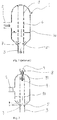
- Figure 1 shows an example of a mixing apparatus according to prior art, where the mixing apparatus is exemplified as a container 1.
- the container 1 has an inlet 2 for a multiphase flow.
- the multiphase flow comprises a mixture of at least a first fluid phase having a first density, e.g. a liquid, and a second fluid phase having a second density, e.g. a gas.
- the liquid level inside the container 1 is shown as a gas-liquid interface 10.
- a hollow flow regulating device 4 is axially arranged inside the container 1, connected at an upper part of the inner surface of the container 1, and extending in a fixed distance towards the outlet 3.
- the flow regulating device 4 opens towards the outlet 3 through discharge means 7.
- the flow regulating device 4 is provided with perforations 6 along its circumference, which perforations 6 extend along the axial length of the flow regulating device 4.
- a drainage gap 5 forms a fixed drainage area between the lower axial end of the flow regulating device 4 and the outlet 3.
- Multiphase flow entering through inlet 2 will, due to gravity, separate in a gas phase and a liquid phase inside the container 1, shown by the gas-liquid interface 10.
- the gas flows through the perforations 6 to the inside of the flow regulating device 4.
- the liquid which due to gravity separates in the lower part of the container 1 closest to the outlet 3, draws out gas through the discharge means 7 and the mixed gas-liquid flow flows through the outlet 3 as a homogenous flow.
- This is due to a pressure difference between the inside of the container 1 and downstream the outlet 3.
- the pressure difference might be created by a narrowing of the flow area, e.g a venturi (not shown), or by a pump creating a suction pressure.
- FIG. 2 shows an embodiment of the mixing apparatus according to the present invention. Similar to figure 1 there is shown a container 1 having an inlet 2 for a multiphase flow. An outlet 3 is arranged at the lower axial end of the container 1. The liquid level inside the container 1 is shown as a gas-liquid interface 10. A hollow flow regulating device 4 is axially arranged inside the container 1, connected to an adjustment device 8 in the upper axial end of the container, which adjustment device 8 comprises a flexible arrangement 11 and an external interface 9. The flow regulating device 4 opens towards the outlet 3 through discharge means 7. Further, the flow regulating device 4 is provided with perforations 6 along its circumference, which perforations 6 extend along the axial length of the flow regulating device 4.
- the external interface 9 is arranged on the outside of the container 1 and can be manipulated from the outside.
- the external interface 9 might be in the form of a screw, bolt or any other interface suitable for manipulation by a ROV manipulator, a torque tool or an actuator wired to a subsea control system (not shown).
- the position adjustment device 8 By manipulating the external interface 9 of the position adjustment device 8, the position adjustment device 8 causes the flow regulating device 4 to move in the axial direction such that the drainage gap 5, and thus the drainage area, between the lower axial end of the flow regulating device 4 and the outlet 3, is modified.
- the drainage gap 5 may be adjusted according to the multiphase flow mixture.
- Moving the flow regulation device 4 away from the outlet 3, will lead to that a larger amount of liquid will flow out of the container 1.
- moving the flow regulating device 4 towards the outlet 3 a larger amount of gas will flow out of the container 3.
- the flow regulating device 4 can be moved away from the outlet 3, allowing sand or debris to be flushed out through the outlet 3.
Landscapes
- Chemical & Material Sciences (AREA)
- Chemical Kinetics & Catalysis (AREA)
- Dispersion Chemistry (AREA)
- Accessories For Mixers (AREA)
Description
- The invention relates to a subsea multiphase flow mixing apparatus, and an associated method, that includes a flow mixer having an inlet for a multiphase flow and an adjustable gas/ liquid outlet.
- It is a common practice within the field of subsea fluid handling to allow the well flow from subsea wells to enter a flow mixer in order to mix or homogenize the well flow or production flow. This is normally performed in order to avoid gas/liquid slug flow and to provide stable operating conditions for the multiphase pump, which multiphase pump is arranged downstream of the flow mixer. The flow mixer breaks the energy of the slug flow, smoothes any fluctuations in the flow, and acts as a sand trap. A slug flow is normally referred to as a multiphase fluid flow regime characterized by a series of liquid plugs (slugs) separated by relatively large gas pockets. In vertical flow, the bubble is an axially symmetrical bullet shape that occupies almost the entire cross-sectional area of a tubing. The resulting flow alternates between high-liquid composition and high-gas composition.
- A conventional subsea flow mixer is designed as an accumulator having a fixed flow restriction on the liquid outlet. The flow area of the restriction is set based on the expected well flow profile, e.g. production flow, and should prevent complete draining of the liquid during a gas slug, and overfilling during a liquid slug. The slug dampening effect of the flow mixer is dependent on the flow area of the restriction and the size and geometry of the flow mixer vessel.
- A conservatively designed flow mixer, e.g. designed for the worst combination of nominal flow and slug during the life of the field, would result in a flow mixer having a physical size that is impractical for integration in a manifold or pump module. If the flow mixer is made smaller, the effective operating range is narrowed, and replacement may be required at some stage. Intervention costs relating to retrieval and re-installation of subsea modules, manifolds in particular, are significant.
- From document
US 5035842 , which discloses an apparatus in accordance with the preamble of claim 1, it is known to feed a non-homogenous mixture of liquid and gas into a vessel to form a body of gas above a pool of liquid. Liquid is fed from the pool through a discharge pipe containing a constriction forming a venturi. Gas is drawn from the gas body through a pipe extending through the liquid pool into the discharge pipe to effect mixing of the liquid and the gas in the venturi. Perforations in the discharge pipe adjust the amounts of gas and liquid leaving the vessel to maintain both liquid and gas within the vessel. - In document
US 5135684 it is disclosed a multiphase process mixing and measuring system. A liquid is supplied to a vessel to form a pool from which it discharges through a venturi. A supply pipe or pipes convey other liquids and/or gases from separate sources or from above the liquid pool into the venturi for mixing with the liquid. The supply pipes can extend through the pool and be perforated to tend to maintain the level of the pool. Associated with the venturi are pressure sensors for measuring flow and densitometer permitting mass flow rate measurements of gas and liquid phases. The apparatus can be incorporated in a cartridge for reception in a receptacle at a subsea installation. - An object of the invention is to adjust the flow of a gas and liquid in a mixing apparatus in situ, e.g. subsea, without retrieving the apparatus to the surface.
- Another object of the invention is to be able to increase the liquid drainage area as part of a contingency plan to flush out sand and debris from the flow mixer.
- The invention is set forth and characterized in the independent claims, while the dependent claims describe other characteristics of the invention.
- The invention concerns an apparatus for mixing at least a first fluid phase having a first density and a second fluid phase having a second density. The apparatus comprises; at least one container, the container comprising at least one inlet for a multiphase flow and at least one outlet at a lower axial end of the container, a hollow flow regulating device axially arranged within the container, wherein a first end of the flow regulating device is arranged in a distance from the outlet providing a drainage gap between the flow regulating device and the outlet, which drainage gap has a drainage area. The flow regulating device comprises a number of perforations along the axial length thereof and a discharge means in a first end, which discharge means opens towards the outlet. The flow regulating device is connected to a position adjustment device, the position adjustment device is arranged to move the flow regulating device in the axial direction, thereby adjusting the drainage area of the drainage gap. The flow regulating device is movable. In a preferred embodiment the first fluid phase is a liquid, while the second fluid phase is a gas.
In another embodiment, there may be arranged a first inlet, e.g. a liquid inlet, and a second inlet, e.g. a gas inlet, instead of one multiphase flow inlet. - There might be arranged one, two or a number of perforations along the axial length of the flow regulating device, the perforations extending along the circumference of the flow regulating device. The perforations might have any diameter that allows the liquid or gas to flow through them. A restriction in the number of perforations will slow down the liquid flow inside the container.
Dependent on the multiphase well flow or production flow mixture entering the container, the drainage gap may be adjusted according to the well flow mixture. Moving the flow regulation device away from the outlet, will result in that a larger amount of liquid will flow out of the container. Correspondingly, moving the flow regulating device towards the outlet, a larger amount of gas will flow out of the container. Another application of the invention might be to flush out sand or debris trapped at the outlet in the container. The sand or debris can be flushed by moving the flow regulation device away from the outlet, allowing the sand or debris to flush through the outlet. - The liquid, which due to gravity tend to collect in the lower part of the container closest to the outlet, draws along gas through the outlet and creates a gas/liquid mixture. This is due to a pressure difference between the inside of the container and downstream the outlet outside the container. The pressure difference might be created by a narrowing, e.g a venturi, by a pump, or similar means well known to a person skilled in the art. The gas is drawn from the gas phase, i.e. the gas is normally in the upper part of the container, through the flow regulating device extending through the liquid into the discharge means to effect mixing of the liquid and the gas through the outlet.
- In an embodiment of the apparatus, the position adjustment device may be connected to a second end of the flow regulating device.
- In another embodiment the multiphase flow separates in at least the first fluid phase and the second fluid phase in the container, the inlet and outlet being arranged such that the fluid phase having the largest density separates at the lower axial end closest to the outlet.
- In an embodiment the container converges as an abutted cone at the outlet. The abutted cone may have a linear-shape, curve-shape, funnel-shape or throat-shape.
- In an embodiment is the diameter of the flow regulating device substantially equal to the diameter of the outlet.
- In another embodiment the position adjustment device comprises an external interface arranged on the outside of the container.
- In an embodiment the external interface is provided to be manipulated by the means of a ROV manipulator, a torque tool, or an actuator wired to a subsea control system. The external interface might in the form of a screw, bolt or any other interface suitable for manipulation by one of said means for manipulation. By manipulating the external interface, the position adjustment device is activated and the movable flow regulating device is moved in the axial direction such that the drainage gap, and thus the drainage area, between the lower axial end of the flow regulating device and the outlet, is modified. Dependent on the mixture of the multiphase flow through the inlet, the drainage gap may be adjusted according to the mixture of the multiphase flow.
- In an embodiment the apparatus may include measuring means, measuring the flow rates of the components in the multiphase flow, and, dependent on the measured flow rates, one may adjust the drainage area by moving the flow regulating device in the axial direction thereof allowing more or less gas or liquid to flow through the outlet.
- The invention also relates to a method of mixing at least a first fluid phase having a first density and a second fluid phase having a second density. The method comprising the steps of;
- providing at least one container, the container comprising at least one inlet for a multiphase flow and at least one outlet at a lower axial end of the container,
- arranging a hollow flow regulating device axially within the container, a first end of the flow regulating device is arranged in a distance from the outlet providing a drainage gap between the flow regulating device and the outlet, which drainage gap has a drainage area, the flow regulating device comprising a number of perforations along the axial length thereof and a discharge means in a first end, which discharge means opens towards the outlet,
- connecting the flow regulating device to a position adjustment device,
- adjusting the drainage area of the drainage gap by manipulating the position adjustment device.
- The invention will now be described in non-limiting embodiments and with reference to the attached drawings, wherein;
-
-
Figure 1 shows an example of a mixing apparatus according to prior art. -
Figure 2 shows an embodiment of the mixing apparatus according to the present invention. -
Figure 1 shows an example of a mixing apparatus according to prior art, where the mixing apparatus is exemplified as a container 1. The container 1 has aninlet 2 for a multiphase flow. The multiphase flow comprises a mixture of at least a first fluid phase having a first density, e.g. a liquid, and a second fluid phase having a second density, e.g. a gas. There is arranged anoutlet 3 at the lower axial end of the container 1. The liquid level inside the container 1 is shown as a gas-liquid interface 10. A hollowflow regulating device 4 is axially arranged inside the container 1, connected at an upper part of the inner surface of the container 1, and extending in a fixed distance towards theoutlet 3. Theflow regulating device 4 opens towards theoutlet 3 through discharge means 7. Further, theflow regulating device 4 is provided with perforations 6 along its circumference, which perforations 6 extend along the axial length of theflow regulating device 4. A drainage gap 5 forms a fixed drainage area between the lower axial end of theflow regulating device 4 and theoutlet 3. Multiphase flow entering throughinlet 2 will, due to gravity, separate in a gas phase and a liquid phase inside the container 1, shown by the gas-liquid interface 10. The gas flows through the perforations 6 to the inside of theflow regulating device 4. The liquid, which due to gravity separates in the lower part of the container 1 closest to theoutlet 3, draws out gas through the discharge means 7 and the mixed gas-liquid flow flows through theoutlet 3 as a homogenous flow. This is due to a pressure difference between the inside of the container 1 and downstream theoutlet 3. The pressure difference might be created by a narrowing of the flow area, e.g a venturi (not shown), or by a pump creating a suction pressure. -
Figure 2 shows an embodiment of the mixing apparatus according to the present invention. Similar tofigure 1 there is shown a container 1 having aninlet 2 for a multiphase flow. Anoutlet 3 is arranged at the lower axial end of the container 1. The liquid level inside the container 1 is shown as a gas-liquid interface 10. A hollowflow regulating device 4 is axially arranged inside the container 1, connected to anadjustment device 8 in the upper axial end of the container, whichadjustment device 8 comprises aflexible arrangement 11 and an external interface 9. Theflow regulating device 4 opens towards theoutlet 3 through discharge means 7. Further, theflow regulating device 4 is provided with perforations 6 along its circumference, which perforations 6 extend along the axial length of theflow regulating device 4. The external interface 9 is arranged on the outside of the container 1 and can be manipulated from the outside. The external interface 9 might be in the form of a screw, bolt or any other interface suitable for manipulation by a ROV manipulator, a torque tool or an actuator wired to a subsea control system (not shown). By manipulating the external interface 9 of theposition adjustment device 8, theposition adjustment device 8 causes theflow regulating device 4 to move in the axial direction such that the drainage gap 5, and thus the drainage area, between the lower axial end of theflow regulating device 4 and theoutlet 3, is modified. Dependent on the mixture of the multiphase flow through theinlet 2, the drainage gap 5 may be adjusted according to the multiphase flow mixture. Moving theflow regulation device 4 away from theoutlet 3, will lead to that a larger amount of liquid will flow out of the container 1. Correspondingly, moving theflow regulating device 4 towards theoutlet 3, a larger amount of gas will flow out of thecontainer 3. In cases where sand or debris has gathered at theoutlet 3, theflow regulating device 4 can be moved away from theoutlet 3, allowing sand or debris to be flushed out through theoutlet 3. - By the use of the arrangement as described herein, one is able to adjust the amount of liquid and/or gas flowing out from the flow mixer through the outlet, and thus minimize slug flow.
- The invention is herein described in non-limiting embodiments. A person skilled in the art will understand that there may be made alterations and modifications to the embodiments that are within the scope of the invention as described in the attached claims.
Claims (9)
- An apparatus for mixing at least a first fluid phase having a first density and a second fluid phase having a second density, the apparatus comprising; at least one container (1), the container comprising at least one inlet (2) for a multiphase flow and at least one outlet (3) at a lower axial end of the container (1), a hollow flow regulating device (4) axially arranged within the container (1), wherein a first end of the flow regulating device (4) is arranged in a distance from the outlet (3) providing a drainage gap (5) between the flow regulating device (4) and the outlet (3), which drainage gap (5) has a drainage area, the flow regulating device (4) comprising a number of perforations (6) along the axial length thereof and a discharge means (7) in a first end, which discharge means (7) opens towards the outlet (3), characterized in that the flow regulating device (4) is connected to a position adjustment device (8), the position adjustment device (8) being arranged to move the flow regulating device (4) in the axial direction, thereby adjusting the drainage area of the drainage gap (5).
- An apparatus according to claim 1, characterized in that the position adjustment device (8) is connected to a second end of the flow regulating device (4) via a flexible arrangement (11).
- An apparatus according to claims 1-2, characterized in that the inlet (2) and outlet (3) are arranged such that when a multiphase flow is separated in at least a first fluid phase and a second fluid phase in the container (2), the fluid phase having the largest density will separate at the lower axial end, closest to the outlet (3).
- An apparatus according to claims 1-3, characterized in that the container (1) converges as an abutted cone at the outlet (3).
- An apparatus according to claims 1-4, characterized in that the diameter of the flow regulating device (4) is substantially equal to the diameter of the outlet (3).
- An apparatus according to claims 1-2, characterized in that the position adjustment device (8) comprises an external interface (9) arranged on the outside of the container (1).
- An apparatus according to claim 6, characterized in that the external interface (9) is provided to be manipulated by the means of a ROV manipulator, a torque tool, or an actuator wired to a subsea control system.
- An apparatus according to any of the preceding claims, characterized in that there is arranged a venturi downstream of the outlet.
- Method of mixing at least a first fluid phase having a first density and a second fluid phase having a second density, the method comprising the steps of;- providing at least one container (1), the container (1) comprising at least one inlet (2) for a multiphase flow and at least one outlet (3) at a lower axial end of the container (1),- arranging a hollow flow regulating device (4) axially within the container (1), a first end of the flow regulating device (4) is arranged in a distance from the outlet (3) providing a drainage gap (5) between the flow regulating device (4) and the outlet (3), which drainage gap (5) has a drainage area, the flow regulating device (4) comprising a number of perforations (6) along the axial length thereof and a discharge means (7) in a first end, which discharge means opens towards the outlet (3),- connecting the flow regulating device (4) to a position adjustment device (8),- adjusting the drainage area of the drainage gap (5) by manipulating the position adjustment device (8).
Applications Claiming Priority (2)
| Application Number | Priority Date | Filing Date | Title |
|---|---|---|---|
| NO20120783A NO337168B1 (en) | 2012-07-05 | 2012-07-05 | Apparatus and method for mixing at least a first and second fluid phases |
| PCT/EP2013/061634 WO2014005785A1 (en) | 2012-07-05 | 2013-06-06 | Multiphase flow mixing apparatus and method of mixing |
Publications (2)
| Publication Number | Publication Date |
|---|---|
| EP2869914A1 EP2869914A1 (en) | 2015-05-13 |
| EP2869914B1 true EP2869914B1 (en) | 2016-05-25 |
Family
ID=48577035
Family Applications (1)
| Application Number | Title | Priority Date | Filing Date |
|---|---|---|---|
| EP13727160.7A Active EP2869914B1 (en) | 2012-07-05 | 2013-06-06 | Multiphase flow mixing apparatus and method of mixing |
Country Status (7)
| Country | Link |
|---|---|
| US (1) | US11241662B2 (en) |
| EP (1) | EP2869914B1 (en) |
| AU (1) | AU2013286194B2 (en) |
| BR (1) | BR112014028541B1 (en) |
| NO (1) | NO337168B1 (en) |
| SG (1) | SG11201407212WA (en) |
| WO (1) | WO2014005785A1 (en) |
Families Citing this family (6)
| Publication number | Priority date | Publication date | Assignee | Title |
|---|---|---|---|---|
| NO337168B1 (en) * | 2012-07-05 | 2016-02-01 | Fmc Kongsberg Subsea As | Apparatus and method for mixing at least a first and second fluid phases |
| US9463424B2 (en) * | 2014-07-09 | 2016-10-11 | Onesubsea Ip Uk Limited | Actuatable flow conditioning apparatus |
| US11458443B2 (en) * | 2018-01-23 | 2022-10-04 | Infuze, Llc | Water bottle device assembly |
| CN109908780B (en) * | 2019-03-28 | 2020-06-12 | 燕山大学 | Self-regulating liquid mixing line |
| CN110270240B (en) * | 2019-06-06 | 2024-05-24 | 常州瑞凯化工装备有限公司 | Dilution steam mixer |
| EP4388885A1 (en) * | 2022-12-23 | 2024-06-26 | Krüger und Salecker Maschinenbau GmbH & Co. KG | Molding machine for producing dimensionally stable products from a mass having a viscosity in the range of from about 10 to 80 pas |
Family Cites Families (24)
| Publication number | Priority date | Publication date | Assignee | Title |
|---|---|---|---|---|
| US487887A (en) | 1892-12-13 | William h | ||
| US517159A (en) * | 1894-03-27 | Robert hartmann | ||
| US1220923A (en) * | 1917-01-23 | 1917-03-27 | Emory Hoge Miller | Churn. |
| US2954144A (en) * | 1957-10-17 | 1960-09-27 | Hiller Aircraft Corp | Storage, mixing and dispensing device |
| US3490655A (en) * | 1966-08-17 | 1970-01-20 | Colgate Palmolive Co | Material blending silo |
| US3855368A (en) * | 1972-04-26 | 1974-12-17 | Ceskoslovenska Akademie Ved | Apparatus for bringing fluid phases into mutual contact |
| US3960175A (en) | 1974-08-16 | 1976-06-01 | Veb Chemieanlagenbau Und Montagekombinat Leipzig | Installation for charging liquids, particularly fermentation liquids, with gas |
| DE3120637A1 (en) * | 1981-05-23 | 1982-12-16 | Ruhrgas Ag, 4300 Essen | DEVICE FOR QUANTITY AND / OR RATIO CONTROL OF TWO GAS AND / OR LIQUID FLOWS |
| US4737349A (en) * | 1985-11-01 | 1988-04-12 | Ciba-Geigy Corporation | Tubular reactor for heterogeneous reactions |
| GB8900841D0 (en) * | 1989-01-16 | 1989-03-08 | Framo Dev Ltd | Homogenization of a multi-phase fluid |
| GB8910372D0 (en) * | 1989-05-05 | 1989-06-21 | Framo Dev Ltd | Multiphase process mixing and measuring system |
| DK0549440T3 (en) * | 1991-12-27 | 1997-03-24 | Inst Francais Du Petrole | Process for optimizing a device for controlling and attenuating a multi-phase flow and device obtained by the method |
| FR2722587B1 (en) * | 1994-07-13 | 1996-08-30 | Inst Francais Du Petrole | REGULATOR BALL FOR POLOYPHASIC EFFLUENTS AND ASSOCIATED COLLECTION MEANS |
| US6000446A (en) * | 1998-03-16 | 1999-12-14 | Xerox Corporation | Apparatus for particulate processing |
| US6200014B1 (en) * | 1998-12-31 | 2001-03-13 | Cortana Corporation | Method and apparatus for mixing high molecular weight materials with liquids |
| GB9910160D0 (en) | 1999-04-30 | 1999-06-30 | Framo Eng As | Apparatus and method for fluid measurement |
| FR2808455B1 (en) * | 2000-05-03 | 2003-02-14 | Schlumberger Services Petrol | INSTALLATION AND METHOD FOR SEPARATING MULTIPHASIC EFFLUENTS |
| CN2601726Y (en) * | 2002-12-30 | 2004-02-04 | 石油大学(北京) | Mixing-equal buffer device of multiphase liquid for oil, gas and water |
| EP1930069B1 (en) * | 2006-12-09 | 2010-09-15 | Haldor Topsoe A/S | Method and apparatus for mixing two or more fluid streams |
| GB2483438A (en) * | 2010-09-06 | 2012-03-14 | Framo Eng As | Homogenising a multiphase fluid |
| US8708049B2 (en) * | 2011-04-29 | 2014-04-29 | Schlumberger Technology Corporation | Downhole mixing device for mixing a first fluid with a second fluid |
| US20120276648A1 (en) * | 2011-04-29 | 2012-11-01 | Schlumberger Technology Corporation | Electrostatically stabilized metal sulfide nanoparticles for colorimetric measurement of hydrogen sulfide |
| US9249661B2 (en) * | 2012-01-20 | 2016-02-02 | Schlumberger Technology Corporation | Apparatus and methods for determining commingling compatibility of fluids from different formation zones |
| NO337168B1 (en) * | 2012-07-05 | 2016-02-01 | Fmc Kongsberg Subsea As | Apparatus and method for mixing at least a first and second fluid phases |
-
2012
- 2012-07-05 NO NO20120783A patent/NO337168B1/en unknown
-
2013
- 2013-06-06 EP EP13727160.7A patent/EP2869914B1/en active Active
- 2013-06-06 AU AU2013286194A patent/AU2013286194B2/en active Active
- 2013-06-06 US US14/396,460 patent/US11241662B2/en active Active
- 2013-06-06 WO PCT/EP2013/061634 patent/WO2014005785A1/en not_active Ceased
- 2013-06-06 SG SG11201407212WA patent/SG11201407212WA/en unknown
- 2013-06-06 BR BR112014028541-1A patent/BR112014028541B1/en active IP Right Grant
Non-Patent Citations (1)
| Title |
|---|
| None * |
Also Published As
| Publication number | Publication date |
|---|---|
| WO2014005785A1 (en) | 2014-01-09 |
| SG11201407212WA (en) | 2014-12-30 |
| EP2869914A1 (en) | 2015-05-13 |
| NO337168B1 (en) | 2016-02-01 |
| US11241662B2 (en) | 2022-02-08 |
| BR112014028541B1 (en) | 2021-03-02 |
| US20150092513A1 (en) | 2015-04-02 |
| BR112014028541A2 (en) | 2017-06-27 |
| NO20120783A1 (en) | 2014-01-06 |
| AU2013286194B2 (en) | 2017-04-27 |
| AU2013286194A1 (en) | 2014-11-27 |
Similar Documents
| Publication | Publication Date | Title |
|---|---|---|
| US11241662B2 (en) | Multiphase flow mixing apparatus and method of mixing | |
| DE60034462T2 (en) | DEVICE FOR SEPARATING A FLUID IN PARTICULAR IN A GAS AND A LIQUID PHASE | |
| US8529772B2 (en) | Method and apparatus for fluid separation | |
| AU2015253679B2 (en) | Multiphase separation system | |
| CA2304924C (en) | Device for separating a mixture of fluids | |
| AU2013366546B2 (en) | Method for separating substances mixed in fluids from oil wells | |
| US8945399B2 (en) | Systems and methods for separating sand from oil | |
| US20060027372A1 (en) | Device for improving oil and gas recovery in wells | |
| NO316088B1 (en) | Fluid separator and method for separating fluids of different densities in a stream through a flow line | |
| EP2880313B1 (en) | Method for operating a multi-phase pump | |
| CN1319619C (en) | Method and device for separating a mixture of fluids | |
| US20180154282A1 (en) | Method and device for separation of liquids and gas with use of inclined and rounded holes or channels in the wall of a pipe | |
| BR112016016083B1 (en) | MODULAR SUBSEA INSTALLATION, LIQUID/GAS SEPARATION UNIT DEVICE, METHOD OF CARRYING OUT A MODULAR INSTALLATION AND TWO PHASE SEPARATION METHOD | |
| EP2442880B1 (en) | A separator tank for separating oil and gas from water | |
| JP6236347B2 (en) | Separation apparatus and separation method | |
| US20140008297A1 (en) | Separation method and separation device | |
| EA012384B1 (en) | Device for controlling slugging | |
| US11236600B2 (en) | Method for control of an inner tube of an inclined tubular oil and water separator | |
| US20120211230A1 (en) | Subsea separation systems | |
| CN108266367A (en) | Fluid delivery system | |
| CN112443298B (en) | Self-adaptive oil well fluid control device and adjusting mechanism | |
| US10864464B2 (en) | Tailings recovery system | |
| SU977725A1 (en) | Method and device for removing liquid from bottom of gas wells | |
| CN120444011A (en) | Separation structure and separation method | |
| WO2004111387A1 (en) | Transferring slurry from a vessel |
Legal Events
| Date | Code | Title | Description |
|---|---|---|---|
| PUAI | Public reference made under article 153(3) epc to a published international application that has entered the european phase |
Free format text: ORIGINAL CODE: 0009012 |
|
| 17P | Request for examination filed |
Effective date: 20141010 |
|
| AK | Designated contracting states |
Kind code of ref document: A1 Designated state(s): AL AT BE BG CH CY CZ DE DK EE ES FI FR GB GR HR HU IE IS IT LI LT LU LV MC MK MT NL NO PL PT RO RS SE SI SK SM TR |
|
| AX | Request for extension of the european patent |
Extension state: BA ME |
|
| DAX | Request for extension of the european patent (deleted) | ||
| GRAP | Despatch of communication of intention to grant a patent |
Free format text: ORIGINAL CODE: EPIDOSNIGR1 |
|
| INTG | Intention to grant announced |
Effective date: 20160211 |
|
| GRAS | Grant fee paid |
Free format text: ORIGINAL CODE: EPIDOSNIGR3 |
|
| GRAA | (expected) grant |
Free format text: ORIGINAL CODE: 0009210 |
|
| AK | Designated contracting states |
Kind code of ref document: B1 Designated state(s): AL AT BE BG CH CY CZ DE DK EE ES FI FR GB GR HR HU IE IS IT LI LT LU LV MC MK MT NL NO PL PT RO RS SE SI SK SM TR |
|
| REG | Reference to a national code |
Ref country code: GB Ref legal event code: FG4D |
|
| REG | Reference to a national code |
Ref country code: CH Ref legal event code: EP |
|
| REG | Reference to a national code |
Ref country code: IE Ref legal event code: FG4D Ref country code: AT Ref legal event code: REF Ref document number: 801788 Country of ref document: AT Kind code of ref document: T Effective date: 20160615 |
|
| REG | Reference to a national code |
Ref country code: FR Ref legal event code: PLFP Year of fee payment: 4 |
|
| REG | Reference to a national code |
Ref country code: DE Ref legal event code: R096 Ref document number: 602013007993 Country of ref document: DE |
|
| REG | Reference to a national code |
Ref country code: LT Ref legal event code: MG4D |
|
| REG | Reference to a national code |
Ref country code: NL Ref legal event code: MP Effective date: 20160525 |
|
| PG25 | Lapsed in a contracting state [announced via postgrant information from national office to epo] |
Ref country code: NL Free format text: LAPSE BECAUSE OF FAILURE TO SUBMIT A TRANSLATION OF THE DESCRIPTION OR TO PAY THE FEE WITHIN THE PRESCRIBED TIME-LIMIT Effective date: 20160525 Ref country code: LT Free format text: LAPSE BECAUSE OF FAILURE TO SUBMIT A TRANSLATION OF THE DESCRIPTION OR TO PAY THE FEE WITHIN THE PRESCRIBED TIME-LIMIT Effective date: 20160525 Ref country code: NO Free format text: LAPSE BECAUSE OF FAILURE TO SUBMIT A TRANSLATION OF THE DESCRIPTION OR TO PAY THE FEE WITHIN THE PRESCRIBED TIME-LIMIT Effective date: 20160825 Ref country code: FI Free format text: LAPSE BECAUSE OF FAILURE TO SUBMIT A TRANSLATION OF THE DESCRIPTION OR TO PAY THE FEE WITHIN THE PRESCRIBED TIME-LIMIT Effective date: 20160525 |
|
| REG | Reference to a national code |
Ref country code: AT Ref legal event code: MK05 Ref document number: 801788 Country of ref document: AT Kind code of ref document: T Effective date: 20160525 |
|
| PG25 | Lapsed in a contracting state [announced via postgrant information from national office to epo] |
Ref country code: ES Free format text: LAPSE BECAUSE OF FAILURE TO SUBMIT A TRANSLATION OF THE DESCRIPTION OR TO PAY THE FEE WITHIN THE PRESCRIBED TIME-LIMIT Effective date: 20160525 Ref country code: PT Free format text: LAPSE BECAUSE OF FAILURE TO SUBMIT A TRANSLATION OF THE DESCRIPTION OR TO PAY THE FEE WITHIN THE PRESCRIBED TIME-LIMIT Effective date: 20160926 Ref country code: RS Free format text: LAPSE BECAUSE OF FAILURE TO SUBMIT A TRANSLATION OF THE DESCRIPTION OR TO PAY THE FEE WITHIN THE PRESCRIBED TIME-LIMIT Effective date: 20160525 Ref country code: LV Free format text: LAPSE BECAUSE OF FAILURE TO SUBMIT A TRANSLATION OF THE DESCRIPTION OR TO PAY THE FEE WITHIN THE PRESCRIBED TIME-LIMIT Effective date: 20160525 Ref country code: SE Free format text: LAPSE BECAUSE OF FAILURE TO SUBMIT A TRANSLATION OF THE DESCRIPTION OR TO PAY THE FEE WITHIN THE PRESCRIBED TIME-LIMIT Effective date: 20160525 Ref country code: GR Free format text: LAPSE BECAUSE OF FAILURE TO SUBMIT A TRANSLATION OF THE DESCRIPTION OR TO PAY THE FEE WITHIN THE PRESCRIBED TIME-LIMIT Effective date: 20160826 |
|
| PG25 | Lapsed in a contracting state [announced via postgrant information from national office to epo] |
Ref country code: BE Free format text: LAPSE BECAUSE OF NON-PAYMENT OF DUE FEES Effective date: 20160630 |
|
| REG | Reference to a national code |
Ref country code: DE Ref legal event code: R119 Ref document number: 602013007993 Country of ref document: DE |
|
| PG25 | Lapsed in a contracting state [announced via postgrant information from national office to epo] |
Ref country code: CZ Free format text: LAPSE BECAUSE OF FAILURE TO SUBMIT A TRANSLATION OF THE DESCRIPTION OR TO PAY THE FEE WITHIN THE PRESCRIBED TIME-LIMIT Effective date: 20160525 Ref country code: DK Free format text: LAPSE BECAUSE OF FAILURE TO SUBMIT A TRANSLATION OF THE DESCRIPTION OR TO PAY THE FEE WITHIN THE PRESCRIBED TIME-LIMIT Effective date: 20160525 Ref country code: EE Free format text: LAPSE BECAUSE OF FAILURE TO SUBMIT A TRANSLATION OF THE DESCRIPTION OR TO PAY THE FEE WITHIN THE PRESCRIBED TIME-LIMIT Effective date: 20160525 Ref country code: RO Free format text: LAPSE BECAUSE OF FAILURE TO SUBMIT A TRANSLATION OF THE DESCRIPTION OR TO PAY THE FEE WITHIN THE PRESCRIBED TIME-LIMIT Effective date: 20160525 Ref country code: SK Free format text: LAPSE BECAUSE OF FAILURE TO SUBMIT A TRANSLATION OF THE DESCRIPTION OR TO PAY THE FEE WITHIN THE PRESCRIBED TIME-LIMIT Effective date: 20160525 |
|
| REG | Reference to a national code |
Ref country code: CH Ref legal event code: PL |
|
| PG25 | Lapsed in a contracting state [announced via postgrant information from national office to epo] |
Ref country code: PL Free format text: LAPSE BECAUSE OF FAILURE TO SUBMIT A TRANSLATION OF THE DESCRIPTION OR TO PAY THE FEE WITHIN THE PRESCRIBED TIME-LIMIT Effective date: 20160525 Ref country code: AT Free format text: LAPSE BECAUSE OF FAILURE TO SUBMIT A TRANSLATION OF THE DESCRIPTION OR TO PAY THE FEE WITHIN THE PRESCRIBED TIME-LIMIT Effective date: 20160525 Ref country code: BE Free format text: LAPSE BECAUSE OF FAILURE TO SUBMIT A TRANSLATION OF THE DESCRIPTION OR TO PAY THE FEE WITHIN THE PRESCRIBED TIME-LIMIT Effective date: 20160525 Ref country code: SM Free format text: LAPSE BECAUSE OF FAILURE TO SUBMIT A TRANSLATION OF THE DESCRIPTION OR TO PAY THE FEE WITHIN THE PRESCRIBED TIME-LIMIT Effective date: 20160525 |
|
| REG | Reference to a national code |
Ref country code: IE Ref legal event code: MM4A |
|
| PG25 | Lapsed in a contracting state [announced via postgrant information from national office to epo] |
Ref country code: MC Free format text: LAPSE BECAUSE OF FAILURE TO SUBMIT A TRANSLATION OF THE DESCRIPTION OR TO PAY THE FEE WITHIN THE PRESCRIBED TIME-LIMIT Effective date: 20160525 |
|
| PLBE | No opposition filed within time limit |
Free format text: ORIGINAL CODE: 0009261 |
|
| STAA | Information on the status of an ep patent application or granted ep patent |
Free format text: STATUS: NO OPPOSITION FILED WITHIN TIME LIMIT |
|
| PG25 | Lapsed in a contracting state [announced via postgrant information from national office to epo] |
Ref country code: DE Free format text: LAPSE BECAUSE OF NON-PAYMENT OF DUE FEES Effective date: 20170103 Ref country code: LI Free format text: LAPSE BECAUSE OF NON-PAYMENT OF DUE FEES Effective date: 20160630 Ref country code: CH Free format text: LAPSE BECAUSE OF NON-PAYMENT OF DUE FEES Effective date: 20160630 |
|
| 26N | No opposition filed |
Effective date: 20170228 |
|
| REG | Reference to a national code |
Ref country code: FR Ref legal event code: PLFP Year of fee payment: 5 |
|
| PG25 | Lapsed in a contracting state [announced via postgrant information from national office to epo] |
Ref country code: IE Free format text: LAPSE BECAUSE OF NON-PAYMENT OF DUE FEES Effective date: 20160606 Ref country code: SI Free format text: LAPSE BECAUSE OF FAILURE TO SUBMIT A TRANSLATION OF THE DESCRIPTION OR TO PAY THE FEE WITHIN THE PRESCRIBED TIME-LIMIT Effective date: 20160525 |
|
| REG | Reference to a national code |
Ref country code: FR Ref legal event code: PLFP Year of fee payment: 6 |
|
| PG25 | Lapsed in a contracting state [announced via postgrant information from national office to epo] |
Ref country code: HU Free format text: LAPSE BECAUSE OF FAILURE TO SUBMIT A TRANSLATION OF THE DESCRIPTION OR TO PAY THE FEE WITHIN THE PRESCRIBED TIME-LIMIT; INVALID AB INITIO Effective date: 20130606 |
|
| PG25 | Lapsed in a contracting state [announced via postgrant information from national office to epo] |
Ref country code: HR Free format text: LAPSE BECAUSE OF FAILURE TO SUBMIT A TRANSLATION OF THE DESCRIPTION OR TO PAY THE FEE WITHIN THE PRESCRIBED TIME-LIMIT Effective date: 20160525 Ref country code: CY Free format text: LAPSE BECAUSE OF FAILURE TO SUBMIT A TRANSLATION OF THE DESCRIPTION OR TO PAY THE FEE WITHIN THE PRESCRIBED TIME-LIMIT Effective date: 20160525 Ref country code: MK Free format text: LAPSE BECAUSE OF FAILURE TO SUBMIT A TRANSLATION OF THE DESCRIPTION OR TO PAY THE FEE WITHIN THE PRESCRIBED TIME-LIMIT Effective date: 20160525 Ref country code: MT Free format text: LAPSE BECAUSE OF NON-PAYMENT OF DUE FEES Effective date: 20160630 Ref country code: LU Free format text: LAPSE BECAUSE OF NON-PAYMENT OF DUE FEES Effective date: 20160606 Ref country code: IS Free format text: LAPSE BECAUSE OF FAILURE TO SUBMIT A TRANSLATION OF THE DESCRIPTION OR TO PAY THE FEE WITHIN THE PRESCRIBED TIME-LIMIT Effective date: 20160525 |
|
| PG25 | Lapsed in a contracting state [announced via postgrant information from national office to epo] |
Ref country code: BG Free format text: LAPSE BECAUSE OF FAILURE TO SUBMIT A TRANSLATION OF THE DESCRIPTION OR TO PAY THE FEE WITHIN THE PRESCRIBED TIME-LIMIT Effective date: 20160525 |
|
| PG25 | Lapsed in a contracting state [announced via postgrant information from national office to epo] |
Ref country code: AL Free format text: LAPSE BECAUSE OF FAILURE TO SUBMIT A TRANSLATION OF THE DESCRIPTION OR TO PAY THE FEE WITHIN THE PRESCRIBED TIME-LIMIT Effective date: 20160525 Ref country code: TR Free format text: LAPSE BECAUSE OF FAILURE TO SUBMIT A TRANSLATION OF THE DESCRIPTION OR TO PAY THE FEE WITHIN THE PRESCRIBED TIME-LIMIT Effective date: 20160525 |
|
| REG | Reference to a national code |
Ref country code: FR Ref legal event code: PLFP Year of fee payment: 11 |
|
| P01 | Opt-out of the competence of the unified patent court (upc) registered |
Effective date: 20230523 |
|
| PGFP | Annual fee paid to national office [announced via postgrant information from national office to epo] |
Ref country code: GB Payment date: 20250401 Year of fee payment: 13 |
|
| PGFP | Annual fee paid to national office [announced via postgrant information from national office to epo] |
Ref country code: IT Payment date: 20250522 Year of fee payment: 13 |
|
| PGFP | Annual fee paid to national office [announced via postgrant information from national office to epo] |
Ref country code: FR Payment date: 20250401 Year of fee payment: 13 |