EP2869865B1 - Reducing centrifugal pump bearing wear through dynamic magnetic coupling - Google Patents
Reducing centrifugal pump bearing wear through dynamic magnetic coupling Download PDFInfo
- Publication number
- EP2869865B1 EP2869865B1 EP13736742.1A EP13736742A EP2869865B1 EP 2869865 B1 EP2869865 B1 EP 2869865B1 EP 13736742 A EP13736742 A EP 13736742A EP 2869865 B1 EP2869865 B1 EP 2869865B1
- Authority
- EP
- European Patent Office
- Prior art keywords
- drive
- drive motor
- magnet
- pump
- impeller
- Prior art date
- Legal status (The legal status is an assumption and is not a legal conclusion. Google has not performed a legal analysis and makes no representation as to the accuracy of the status listed.)
- Active
Links
Images



Classifications
-
- F—MECHANICAL ENGINEERING; LIGHTING; HEATING; WEAPONS; BLASTING
- F04—POSITIVE - DISPLACEMENT MACHINES FOR LIQUIDS; PUMPS FOR LIQUIDS OR ELASTIC FLUIDS
- F04D—NON-POSITIVE-DISPLACEMENT PUMPS
- F04D13/00—Pumping installations or systems
- F04D13/02—Units comprising pumps and their driving means
- F04D13/021—Units comprising pumps and their driving means containing a coupling
- F04D13/024—Units comprising pumps and their driving means containing a coupling a magnetic coupling
- F04D13/027—Details of the magnetic circuit
-
- A—HUMAN NECESSITIES
- A61—MEDICAL OR VETERINARY SCIENCE; HYGIENE
- A61M—DEVICES FOR INTRODUCING MEDIA INTO, OR ONTO, THE BODY; DEVICES FOR TRANSDUCING BODY MEDIA OR FOR TAKING MEDIA FROM THE BODY; DEVICES FOR PRODUCING OR ENDING SLEEP OR STUPOR
- A61M60/00—Blood pumps; Devices for mechanical circulatory actuation; Balloon pumps for circulatory assistance
- A61M60/20—Type thereof
- A61M60/205—Non-positive displacement blood pumps
- A61M60/216—Non-positive displacement blood pumps including a rotating member acting on the blood, e.g. impeller
- A61M60/226—Non-positive displacement blood pumps including a rotating member acting on the blood, e.g. impeller the blood flow through the rotating member having mainly radial components
- A61M60/232—Centrifugal pumps
-
- A—HUMAN NECESSITIES
- A61—MEDICAL OR VETERINARY SCIENCE; HYGIENE
- A61M—DEVICES FOR INTRODUCING MEDIA INTO, OR ONTO, THE BODY; DEVICES FOR TRANSDUCING BODY MEDIA OR FOR TAKING MEDIA FROM THE BODY; DEVICES FOR PRODUCING OR ENDING SLEEP OR STUPOR
- A61M60/00—Blood pumps; Devices for mechanical circulatory actuation; Balloon pumps for circulatory assistance
- A61M60/30—Medical purposes thereof other than the enhancement of the cardiac output
- A61M60/36—Medical purposes thereof other than the enhancement of the cardiac output for specific blood treatment; for specific therapy
- A61M60/38—Blood oxygenation
-
- A—HUMAN NECESSITIES
- A61—MEDICAL OR VETERINARY SCIENCE; HYGIENE
- A61M—DEVICES FOR INTRODUCING MEDIA INTO, OR ONTO, THE BODY; DEVICES FOR TRANSDUCING BODY MEDIA OR FOR TAKING MEDIA FROM THE BODY; DEVICES FOR PRODUCING OR ENDING SLEEP OR STUPOR
- A61M60/00—Blood pumps; Devices for mechanical circulatory actuation; Balloon pumps for circulatory assistance
- A61M60/50—Details relating to control
- A61M60/508—Electronic control means, e.g. for feedback regulation
- A61M60/538—Regulation using real-time blood pump operational parameter data, e.g. motor current
-
- F—MECHANICAL ENGINEERING; LIGHTING; HEATING; WEAPONS; BLASTING
- F04—POSITIVE - DISPLACEMENT MACHINES FOR LIQUIDS; PUMPS FOR LIQUIDS OR ELASTIC FLUIDS
- F04D—NON-POSITIVE-DISPLACEMENT PUMPS
- F04D13/00—Pumping installations or systems
- F04D13/02—Units comprising pumps and their driving means
- F04D13/021—Units comprising pumps and their driving means containing a coupling
- F04D13/024—Units comprising pumps and their driving means containing a coupling a magnetic coupling
-
- F—MECHANICAL ENGINEERING; LIGHTING; HEATING; WEAPONS; BLASTING
- F04—POSITIVE - DISPLACEMENT MACHINES FOR LIQUIDS; PUMPS FOR LIQUIDS OR ELASTIC FLUIDS
- F04D—NON-POSITIVE-DISPLACEMENT PUMPS
- F04D13/00—Pumping installations or systems
- F04D13/02—Units comprising pumps and their driving means
- F04D13/06—Units comprising pumps and their driving means the pump being electrically driven
-
- F—MECHANICAL ENGINEERING; LIGHTING; HEATING; WEAPONS; BLASTING
- F04—POSITIVE - DISPLACEMENT MACHINES FOR LIQUIDS; PUMPS FOR LIQUIDS OR ELASTIC FLUIDS
- F04D—NON-POSITIVE-DISPLACEMENT PUMPS
- F04D13/00—Pumping installations or systems
- F04D13/02—Units comprising pumps and their driving means
- F04D13/06—Units comprising pumps and their driving means the pump being electrically driven
- F04D13/0606—Canned motor pumps
- F04D13/064—Details of the magnetic circuit
-
- F—MECHANICAL ENGINEERING; LIGHTING; HEATING; WEAPONS; BLASTING
- F04—POSITIVE - DISPLACEMENT MACHINES FOR LIQUIDS; PUMPS FOR LIQUIDS OR ELASTIC FLUIDS
- F04D—NON-POSITIVE-DISPLACEMENT PUMPS
- F04D15/00—Control, e.g. regulation, of pumps, pumping installations or systems
- F04D15/0027—Varying behaviour or the very pump
-
- F—MECHANICAL ENGINEERING; LIGHTING; HEATING; WEAPONS; BLASTING
- F04—POSITIVE - DISPLACEMENT MACHINES FOR LIQUIDS; PUMPS FOR LIQUIDS OR ELASTIC FLUIDS
- F04D—NON-POSITIVE-DISPLACEMENT PUMPS
- F04D25/00—Pumping installations or systems
- F04D25/02—Units comprising pumps and their driving means
- F04D25/026—Units comprising pumps and their driving means with a magnetic coupling
-
- F—MECHANICAL ENGINEERING; LIGHTING; HEATING; WEAPONS; BLASTING
- F04—POSITIVE - DISPLACEMENT MACHINES FOR LIQUIDS; PUMPS FOR LIQUIDS OR ELASTIC FLUIDS
- F04D—NON-POSITIVE-DISPLACEMENT PUMPS
- F04D27/00—Control, e.g. regulation, of pumps, pumping installations or pumping systems specially adapted for elastic fluids
- F04D27/002—Control, e.g. regulation, of pumps, pumping installations or pumping systems specially adapted for elastic fluids by varying geometry within the pumps, e.g. by adjusting vanes
-
- F—MECHANICAL ENGINEERING; LIGHTING; HEATING; WEAPONS; BLASTING
- F04—POSITIVE - DISPLACEMENT MACHINES FOR LIQUIDS; PUMPS FOR LIQUIDS OR ELASTIC FLUIDS
- F04D—NON-POSITIVE-DISPLACEMENT PUMPS
- F04D29/00—Details, component parts, or accessories
- F04D29/04—Shafts or bearings, or assemblies thereof
- F04D29/041—Axial thrust balancing
-
- F—MECHANICAL ENGINEERING; LIGHTING; HEATING; WEAPONS; BLASTING
- F04—POSITIVE - DISPLACEMENT MACHINES FOR LIQUIDS; PUMPS FOR LIQUIDS OR ELASTIC FLUIDS
- F04D—NON-POSITIVE-DISPLACEMENT PUMPS
- F04D29/00—Details, component parts, or accessories
- F04D29/04—Shafts or bearings, or assemblies thereof
- F04D29/042—Axially shiftable rotors
-
- A—HUMAN NECESSITIES
- A61—MEDICAL OR VETERINARY SCIENCE; HYGIENE
- A61M—DEVICES FOR INTRODUCING MEDIA INTO, OR ONTO, THE BODY; DEVICES FOR TRANSDUCING BODY MEDIA OR FOR TAKING MEDIA FROM THE BODY; DEVICES FOR PRODUCING OR ENDING SLEEP OR STUPOR
- A61M2205/00—General characteristics of the apparatus
- A61M2205/33—Controlling, regulating or measuring
- A61M2205/3331—Pressure; Flow
- A61M2205/3334—Measuring or controlling the flow rate
-
- A—HUMAN NECESSITIES
- A61—MEDICAL OR VETERINARY SCIENCE; HYGIENE
- A61M—DEVICES FOR INTRODUCING MEDIA INTO, OR ONTO, THE BODY; DEVICES FOR TRANSDUCING BODY MEDIA OR FOR TAKING MEDIA FROM THE BODY; DEVICES FOR PRODUCING OR ENDING SLEEP OR STUPOR
- A61M60/00—Blood pumps; Devices for mechanical circulatory actuation; Balloon pumps for circulatory assistance
- A61M60/40—Details relating to driving
- A61M60/403—Details relating to driving for non-positive displacement blood pumps
- A61M60/419—Details relating to driving for non-positive displacement blood pumps the force acting on the blood contacting member being permanent magnetic, e.g. from a rotating magnetic coupling between driving and driven magnets
-
- F—MECHANICAL ENGINEERING; LIGHTING; HEATING; WEAPONS; BLASTING
- F04—POSITIVE - DISPLACEMENT MACHINES FOR LIQUIDS; PUMPS FOR LIQUIDS OR ELASTIC FLUIDS
- F04D—NON-POSITIVE-DISPLACEMENT PUMPS
- F04D1/00—Radial-flow pumps, e.g. centrifugal pumps; Helico-centrifugal pumps
-
- F—MECHANICAL ENGINEERING; LIGHTING; HEATING; WEAPONS; BLASTING
- F04—POSITIVE - DISPLACEMENT MACHINES FOR LIQUIDS; PUMPS FOR LIQUIDS OR ELASTIC FLUIDS
- F04D—NON-POSITIVE-DISPLACEMENT PUMPS
- F04D13/00—Pumping installations or systems
- F04D13/02—Units comprising pumps and their driving means
- F04D13/021—Units comprising pumps and their driving means containing a coupling
- F04D13/024—Units comprising pumps and their driving means containing a coupling a magnetic coupling
- F04D13/026—Details of the bearings
-
- F—MECHANICAL ENGINEERING; LIGHTING; HEATING; WEAPONS; BLASTING
- F04—POSITIVE - DISPLACEMENT MACHINES FOR LIQUIDS; PUMPS FOR LIQUIDS OR ELASTIC FLUIDS
- F04D—NON-POSITIVE-DISPLACEMENT PUMPS
- F04D29/00—Details, component parts, or accessories
- F04D29/18—Rotors
- F04D29/22—Rotors specially for centrifugal pumps
-
- F—MECHANICAL ENGINEERING; LIGHTING; HEATING; WEAPONS; BLASTING
- F04—POSITIVE - DISPLACEMENT MACHINES FOR LIQUIDS; PUMPS FOR LIQUIDS OR ELASTIC FLUIDS
- F04D—NON-POSITIVE-DISPLACEMENT PUMPS
- F04D29/00—Details, component parts, or accessories
- F04D29/60—Mounting; Assembling; Disassembling
- F04D29/605—Mounting; Assembling; Disassembling specially adapted for liquid pumps
Definitions
- Extracorporeal blood pumps are used to assist patient blood circulation in a variety of surgical procedures including both short and relatively longer-term procedures including cardiopulmonary bypass (CPB) Extracorporeal Membrane Oxygenation (ECMO) or Extracorporeal Life Support (ECLS).
- CPB cardiopulmonary bypass
- ECMO Extracorporeal Membrane Oxygenation
- ECLS Extracorporeal Life Support
- One type of blood pump commonly used is a magnetically driven centrifugal blood pump which includes an external drive motor that drives the blood pump via magnetic coupling between a drive motor magnet and a blood pump impeller magnet. Magnetic coupling in this manner allows for the centrifugal blood pump to be housed in a separate and disposable sealed unit and discarded after a single use while the pump drive may be reusable.
- US 5,575,630 A discloses a blood pump used for heart-lung machines and having an impeller, a casing having a suction inlet and a delivery outlet and rotatably encasing the impeller, a magnetic driver disposed outside the casing, and a magnetic attraction force adjuster.
- the impeller has a rotationally symmetric shape, such as a conical shape, is equipped with vanes having a pumping function on the side surface thereof and is also equipped with magnets, such as permanent magnets.
- the magnetic driver for rotating the impeller in cooperation with the magnets is a magnet assembly magnetically connected to the magnets and a rotation driver for rotating the magnet assembly.
- the magnetic attraction force adjuster adjusts the magnetic attraction force generated between the magnets and the magnet assembly by adjusting the gap between the magnets and the magnet assembly.
- One of the pivot and pivot bearing for supporting the rotation shaft of the impeller is made of ceramics and the other is made of synthetic resin.
- Magnetically driven centrifugal blood pumps may include one or more bearings.
- a pump impeller is captured between an upper and a lower bearing and as the impeller spins or turns, the pressure distribution of the pumped fluid (e.g. blood) generates an upward or impeller lift force which acts on the upper bearing.
- the magnetic attraction between the impeller magnet and the drive magnet results in a downward force which acts on the lower bearing.
- the net force on the bearings is the summation of these two forces. Over time, the forces acting on the bearings may result in a finite bearing life. Therefore, it would be advantageous to minimize forces acting on the bearings so as to extend bearing life. Extending the life of the blood pump bearings may advantageously allow for use of the blood pump in extended or longer term procedures or applications.
- aspects of the present disclosure provide an extracorporeal blood pumping system, a method of minimizing wear on at least one of an upper bearing and a lower bearing of a centrifugal blood pump, and a drive motor for an extracorporeal blood pumping system according to the independent claims.
- aspects of the present disclosure provide devices, systems and methods for dynamically adjusting a drive magnet of a pump drive used in an extracorporeal blood pumping system.
- Apparatus and methods according to the disclosure include an extracorporeal blood pumping system comprising a centrifugal blood pump with a pump impeller wherein the pump impeller comprises an impeller magnet.
- the system further comprising a pump drive including a drive motor coupled to a drive magnet.
- the blood pump and pump drive may be coupled together magnetically and may be mechanically coupled together to provide a blood pump-pump drive assembly.
- the drive magnet position may be adjusted such that the distance between the drive magnet and impeller magnet is varied. Adjustment of the drive magnet may comprise axial displacement of the drive magnet.
- Apparatus and methods according to the disclosure also include a blood pump magnetically coupled to a pump drive where the blood pump includes an impeller magnet embedded within a pump impeller and the pump drive includes a drive motor coupled to a drive magnet.
- the pump impeller may be positioned within a blood pump housing between upper and lower bearings. Actuation of the pump impeller may generate a lift force which may cause the pump impeller to act on the upper bearing.
- a magnetic attraction force between the impeller magnet and the drive magnet may cause the pump impeller to act on the lower bearing.
- a stepper motor may be configured to axially displace the drive magnet such that the magnetic attraction force is approximately equal and opposite the lift force. Further, when the magnetic attraction force and lift force are approximately equal and opposite, axial forces acting on the bearings may be minimized.
- aspects according to the disclosure further provide a method of minimizing wear on at least one bearing of a centrifugal blood pump which may include varying the position of a drive magnet of a pump drive coupled to the blood pump such that a magnetic attraction force between an impeller magnet of the blood pump and the drive magnet is approximately equal and opposite a pump impeller lift force.
- the method may comprise varying the position of a drive magnet, varying a relative distance between a drive magnet and an impeller magnet, axially moving or adjusting a drive motor, actuating a stepper motor, and or actuating a drive motor housing and/or drive motor carrier.
- the method may also comprise communicating a drive motor speed to a system controller and may comprise correlating the drive motor speed to a stepper motor position.
- Methods according the disclosure may include a method of adjusting a position of a drive magnet of a pump drive comprising actuating a stepper motor coupled to the drive magnet. Actuating the stepper motor may thereby cause a drive motor housing to spin or turn causing a threadably coupled drive motor carrier to move axially. Where the drive magnet is coupled to the drive motor carrier, axial movement of drive motor carrier may cause the drive magnet to move or adjust axially. Actuation of the stepper motor may comprise transmitting a drive motor speed to a system controller, determining a stepper motor position corresponding to the drive motor speed and actuating the stepper motor. Determining the stepper motor position may comprise referencing a lookup table.
- Methods according to the disclosure may include a method of varying a distance between a blood pump drive magnet and a blood pump impeller magnet including transmitting a drive motor speed from a drive motor to a system controller, determining a drive magnet position based upon the drive motor speed and actuating a stepper motor to displace the drive motor axially which thereby displaces a drive magnet.
- Determining the drive magnet position may comprise referencing a software lookup table or tables.
- the software lookup table may provide a stepper motor position, corresponding to the drive motor speed transmitted to the system controller which may in turn communicate the desired stepper motor position to a stepper controller.
- Actuating the stepper motor may further include sending a stepper motor signal to the stepper motor via wireless telemetry or a wired connection.
- the stepper motor may turn or spin to the position communicated via the signal.
- turning the stepper motor may likewise turn the stepper motor drive shaft which accordingly turns drive motor housing.
- Turning drive motor housing may allow drive motor carrier to move axially allowing the drive magnet to move axially where the drive magnet is coupled to the drive motor by way of a drive motor shaft.
- FIGS. 1A and 2 depict a blood pump 200 of the centrifugal type used to pump blood of a patient, for example to an oxygenator (not shown) during a surgical procedure such as described herein above.
- Blood pump 200 includes a blood pump interface 250 including flange members 252 for coupling to an external pump drive 300 (e.g. FIGS. 1B, 2 ).
- Pump drive 300 likewise includes a pump drive interface 350 including bracket members 354 for capturing flange members 252 to couple blood pump 200 to pump drive 300 and a raised portion 356 which defines an inner recess 352 ( FIG. 4 ).
- pump drive interfaces 250, 350 may comprise various alternative mechanisms for coupling pump drive 200 to blood pump 300 including fittings, brackets, notches, quick connects, clasps, and/or latches. Regardless of the specific coupling mechanism, blood pump 200 and pump drive 300 may be coupled together at the interfaces 250, 350 to define a blood pump-pump drive assembly 100 such as depicted in FIG. 2 .
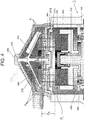
- FIG. 3 depicts the blood pump-pump drive assembly 100 of FIG. 2 in cross section.
- Blood pump 200 comprises a blood pump housing 230, with a blood inlet 232 and a blood outlet 234 extending from the housing 230.
- a pump impeller assembly 210 is contained within the pump housing 230 and comprises a pump impeller 240 configured or adapted to rotate within the housing 230 to move fluid by a centrifugal force generated by the rotation.
- a pump impeller magnet 220 is provided in the pump impeller assembly 210 and may be embedded in pump impeller 240 as shown.
- the pump impeller 240 may comprise one or more bearings and, for example, may be located or captured between an upper pivot bearing 242 and a lower pivot bearing 244. As depicted in the embodiment of FIG.
- Blood pump 200 may comprise any magnetically coupleable centrifugal blood pump and may for example comprise an AFFINITYTM CP centrifugal blood pump manufactured by Medtronic, Inc. of Minneapolis, Minnesota
- the blood pump-pump drive assembly 100 includes pump drive 300 comprising a pump drive housing 330.
- a blood pump drive motor 310 and a thrust force, or pump drive magnet 320, are contained within the pump drive housing 330.
- the drive magnet 320 may comprise one or more magnets.
- the drive motor 310 communicates with a control assembly (e.g. 400 FIG. 6 ) which is configured to actuate the drive motor 310. Actuation of the drive motor 310 actuates the drive magnet 320 via a drive shaft 312. Actuation of the drive magnet 320 causes the drive magnet 320 to spin at the speed (RPM) of the drive motor 310 and thus may comprise direct drive mechanism.
- RPM speed
- systems comprising gearing or transmission (not shown) may be used to drive the drive magnet 320.
- the drive magnet 320 when the drive magnet 320 is located in sufficient proximity to the pump impeller magnet 220, such as when the blood pump 200 is coupled to the pump drive 300, (i.e. as in assembly 100), actuation of the drive magnet 320 generates a torque in the impeller magnet 220 through magnetic coupling which in turn causes pump impeller 240 to spin at the rate of speed (RPM) of the drive magnet 320.
- RPM rate of speed
- Containment of the blood pump 200 in a housing 230 separate from both the drive motor 310 and the pump drive housing 330, enables the blood pump 200 to be discarded after a single use (e.g. after having been contaminated with patient blood during a surgical procedure) while the pump drive 300 may be reusable.
- pump drive 300 includes a drive motor carrier 360 attached to drive motor 310.
- Drive motor carrier 360 is configured to travel or adjust axially upon rotation of a drive motor housing 370 as explained in further detail below. Attachment of the drive motor 310 to the drive motor carrier 360 may be accomplished via socket head cap screws 365 as shown or via any fastening or attaching device or means including, but not limited to adhesives, clips, screws, bolts, pins, rivets, and/or rods.
- Drive motor carrier 360 may comprise a cylinder shape with an open distal or bottom end 364 through which drive motor 310 is allowed to extend, as illustrated in FIG. 3 .
- the drive motor carrier 360 further comprises a wall 366 which may extend to any length L along the drive motor 310.
- wall 366 may extend to any length which allows for sufficient travel of the drive motor 310 and drive magnet 320 such as described in further detail with reference to FIG. 5 .
- the wall 366 may extend to any length above a bottom or distal end 314 of drive motor 310 such as illustrated, to the end 314 or past the end 314.
- drive motor carrier 360 includes an outer surface threaded interface 362 for coupling with an inner surface threaded interface 372 of drive motor housing 370.
- Drive motor carrier 360 may partially, substantially or completely surround a portion of the drive motor 310 and may partially or substantially conform to the shape of the drive motor 310 or may comprise other configurations provided that the drive motor 310 is coupled to the drive motor carrier 360.
- Drive motor housing 370 defines a chamber 371 for receiving the drive motor 310 attached to drive motor carrier 360 and includes an open proximal end 382 configured to allow travel of the drive motor carrier 360, and thus drive motor 310, therethrough.
- the drive motor housing 370 surrounds at least a portion of the drive motor carrier 360 and is coupled to the drive motor carrier 360 via engagement of inner surface threaded interface 372 of housing 370 with outer surface threaded interface 362 of the drive motor carrier 360.
- An outer surface 374 of drive motor housing 370 may abut one or bearings 378 which may comprise any type of bearing, for example the ball bearing as depicted in FIG. 3 . As shown in the example of FIG. 3 , an outer surface 374 of drive motor housing 370 abuts two bearings 378, one at each of a distal end 380 and a proximal end 382 of housing 370.
- the drive motor housing 370 is configured to turn or spin upon actuation of a stepper motor 340.
- Stepper motor 340 may be coupled to drive motor housing 370 via a shaft 342.
- the turning or spinning of drive motor housing 370 causes drive motor carrier 360 to travel axially due to coupling of the drive motor carrier 360 to the drive motor housing 370 at threaded interfaces 362, 372.
- FIG. 5A depicts drive motor carrier 360 with drive motor 310 at a first drive motor height H D1 where H D1 is measured from a distal end inner surface 381 of drive motor housing 370 to a distal end 314 ( FIG. 3 ) of drive motor 310.
- Actuation of stepper motor 340 causes stepper motor drive shaft 342 to rotate thereby turning drive motor housing 370 either clockwise or counterclockwise, depending upon the desired axial positioning of drive magnet 320.
- drive motor carrier 360 may travel axially relative to the distal end 380 of drive motor housing 370.
- Drive motor carrier 360 is configured to travel axially either in a proximal direction or a distal direction (i.e. up or down relative to a bottom or distal end 380 of drive motor housing 370) depending upon clockwise or counterclockwise rotation of drive motor housing 370. Since drive motor carrier 360 is coupled to drive motor 310 and drive magnet 320 is coupled to drive motor 310, axial movement of drive motor carrier 360 axially displaces drive magnet 320.
- drive magnet 320 may comprise a first drive magnet position (e.g.
- Drive magnet 320 in a first drive magnet position P 1 may correspond to the drive motor 310 at a first drive motor height H D1 and may correspond to a distance D M1 between drive magnet 320 and impeller magnet 320.
- drive magnet position P 2 may correspond to the drive motor 310 at a second drive motor height H D2 and a distance D M2 between drive magnet 320 and impeller magnet 220.
- a recess portion 352 ( FIGS. 3-5 ) of pump drive 300 is configured to allow drive magnet 220 to be received therein such as upon upward or proximal axial displacement of the drive magnet 320 toward the impeller magnet 220.
- FIGS. 5A and 5B depict two different positions, P1 and P2 of drive magnet 320. Nevertheless, drive magnet 320 may be positioned at various incremental axial positions, not specifically illustrated. Axial displacement or travel of the drive magnet 320 may be limited or bound at a proximal or upper end by recess portion 352 of drive motor housing 330 such that when a portion of drive magnet 320 is adjacent (e.g. contacts or substantially contacts) an inner surface 353 of recess portion 352, no further upward or proximal travel is allowed.
- distal or downward travel of drive magnet 320 may be limited or bound by drive motor housing distal end 380 such that when a portion of drive motor 310 (or a portion of drive motor carrier 360, if drive motor carrier 360 extends beyond drive motor distal end 314) reaches or is adjacent (e.g. contacts or substantially contacts) drive motor housing distal end 380, no further distal or downward travel of the drive motor carrier 360 or drive motor 310 may be permitted.
- FIG. 4 depicts forces which may act on pump in-ipeller 240.
- a net impeller lift force F L illustrated by upward or proximally directed arrows may be generated as the pump impeller 240 spins.
- Impeller lift force F L is a net pressure distribution force and may vary with pump impeller speed, and fluid (e.g. blood) properties.
- Rotation (RPM) of the pump impeller 240 may cause a pressure differential which generates a Bernouli effect in a rotational motion thereby causing the pump impeller 240 to lift. Also depicted in FIG.
- F M is a net magnetic attraction force, F M , illustrated by downward or distally directed arrows which may be generated between the drive magnet 320 and the impeller magnet 220 when the drive magnet 320 and impeller magnet 220 are in sufficient proximity or located a sufficient distance D M apart. Adjusting the position P M of the drive magnet 320 relative to the impeller magnet 220 may vary the magnetic attraction force F M.
- impeller lift force F L may act on pump impeller 240 such that upper pivot bearing 242 bears against upper bearing surface 236 and may thereby cause upper pivot bearing 242 to undergo wear.
- the magnetic attraction force F M may act on the pump impeller 240 such that lower pivot bearing 244 bears against lower bearing surface 246 and may thereby cause lower pivot bearing 246 to undergo wear.
- the pivot bearings 242, 244 are unidirectional such that if one is loaded, the other is not. Imbalance in forces between the two pivot bearings 244, 246 may generate heat and/or mechanical wear on the pivot bearing experiencing the higher force (e.g. F M or F L ). Often, as the pump impeller 240 spins, the lift force F L generated exceeds the magnetic attraction force F M such that upper pivot bearing 244 experiences more wear. This may be especially true at higher pump or impeller speeds as will be further elucidated in the ensuing discussion. Regardless, a total net force acting on the pivot bearings 244, 246 is the summation of F M and F L .
- varying the magnetic attraction force F M by varying the proximity of the drive magnet 320 to the impeller magnet 220 i.e. varying drive magnet position P M ), such that the magnetic attraction force F M is approximately equal and opposite the lift force F L , may minimize axial forces acting on each of the upper and lower pivot bearings 244, 246.
- varying the relative distance D M between the drive magnet 320 and impeller magnet 220 may comprise in part actuation of a stepper motor 340. Control of the stepper motor 340 is described below with reference to FIG. 6 .
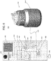
- FIG. 6 illustrates an embodiment of a system 500 including a control assembly 400 for controlling a pump drive 300 coupled to blood pump 200.
- the control assembly 400 may include an external power source 405, a speed control 450, and a graphic user interface 460.
- Pump drive 300 may communicate with the control assembly 400 via a control signal 410.
- Control signal 410 may comprise telemetry or may comprise electrical wiring.
- control assembly 400 may be provided within pump drive housing 330 or may be external to pump drive housing 330 such as depicted in FIG. 6 . Regardless, control signal 410 may comprise several signals for communicating between the drive motor 310, stepper motor 340 and the control assembly 400.
- Control signal 410 may comprise a drive motor power/speed signal 420, a drive motor speed feedback signal 430 and/or a stepper motor signal 440.
- Signals 420 and 430 may communicate between a speed control and power amplifier 425, a system controller 470 CONFIRM and the drive motor 310.
- Signal 440 may communicate between a stepper motor controller and power amplifier 490 and the stepper motor 340.
- system controller 470 is configured to reference a lookup table or tables 480 comprising one or more drive motor speed values each speed value corresponding to one of a plurality of stepper motor position values.
- the software lookup table or tables 480 may be generated by way of characterization studies evaluating lift force F L and magnetic force F M as a function of drive motor speed S ( FIG. 4 ).
- the stepper motor position values may relate to a drive motor height (e.g. H D1 , H D2 ) and/or drive magnet position (P M ) which would tend to balance forces F L and F M at each drive motor speed S during the course of a procedure or during use.
- system 500 is configured to dynamically adjust the drive magnet 320 such that the proximity of the drive magnet 320 and the impeller magnet 220 is varied such that the magnetic force F M is approximately equal and opposite the impeller lift force F L during a use of the system, for example during a surgical procedure.
- preprogrammed or pre-set software lookup tables 480 may comprise any of several incremental drive motor speed values (e.g. S 1 , S 2 , FIG. 5A-B ) corresponding to a pre-determined (e.g.
- stepper motor position where each stepper motor position corresponds to a predetermined a drive magnet position P M , drive motor height H D , or distance D M , which in turn depends upon the desired proximity of the drive magnet 320 to the impeller magnet 220.
- lookup tables 480 may be configured to correlate any incremental drive motor speed S to a particular stepper motor position to thereby provide a particular drive magnet position P M .
- a desired distance D M of the drive magnet 320 and impeller magnet 220 may be that distance between drive magnet 320 and impeller magnet 220 which results in forces F M and F L being approximately balanced or equal.
- FIG. 5A depicts a drive motor 310 at a point in time during operation of pump drive 300 in which the drive motor speed S 1 is lower (e.g. with respect to the drive motor speed S 2 of drive motor 310 depicted in FIG. 5B ).
- lower drive motor speeds may generate lower lift forces F L and therefore an increased tendency in lower pivot bearing 244 to experience bearing wear since the magnetic force F M may be allowed to overcome the lower lift force F L tending to cause lower pivot bearing 244 to bear against bearing surface 246.
- drive magnet 320 may be positioned at a greater distance (e.g. D M1 , FIG.
- drive magnet 320 may be positioned in closer proximity to, or, at a lesser distance from impeller magnet 220 as compared to distance D M1 of FIG. 5A , for example drive magnet 320 may be positioned at a distance D M2 , as depicted in FIG. 5B .
- the magnetic force F M increases, thereby counteracting the increased or higher lift force F L whereby upper pivot bearing 242 may be drawn downward and away from upper bearing surface 236. In this manner, bearing wear on each of the upper pivot bearing 242 and lower pivot bearing 244 may be minimized.
Landscapes
- Engineering & Computer Science (AREA)
- Health & Medical Sciences (AREA)
- Mechanical Engineering (AREA)
- General Engineering & Computer Science (AREA)
- Heart & Thoracic Surgery (AREA)
- Cardiology (AREA)
- Anesthesiology (AREA)
- Biomedical Technology (AREA)
- Hematology (AREA)
- Life Sciences & Earth Sciences (AREA)
- Animal Behavior & Ethology (AREA)
- General Health & Medical Sciences (AREA)
- Public Health (AREA)
- Veterinary Medicine (AREA)
- Emergency Medicine (AREA)
- Geometry (AREA)
- Physics & Mathematics (AREA)
- External Artificial Organs (AREA)
- Structures Of Non-Positive Displacement Pumps (AREA)
Description
- Extracorporeal blood pumps are used to assist patient blood circulation in a variety of surgical procedures including both short and relatively longer-term procedures including cardiopulmonary bypass (CPB) Extracorporeal Membrane Oxygenation (ECMO) or Extracorporeal Life Support (ECLS). One type of blood pump commonly used is a magnetically driven centrifugal blood pump which includes an external drive motor that drives the blood pump via magnetic coupling between a drive motor magnet and a blood pump impeller magnet. Magnetic coupling in this manner allows for the centrifugal blood pump to be housed in a separate and disposable sealed unit and discarded after a single use while the pump drive may be reusable.
-
US 5,575,630 A discloses a blood pump used for heart-lung machines and having an impeller, a casing having a suction inlet and a delivery outlet and rotatably encasing the impeller, a magnetic driver disposed outside the casing, and a magnetic attraction force adjuster. The impeller has a rotationally symmetric shape, such as a conical shape, is equipped with vanes having a pumping function on the side surface thereof and is also equipped with magnets, such as permanent magnets. The magnetic driver for rotating the impeller in cooperation with the magnets is a magnet assembly magnetically connected to the magnets and a rotation driver for rotating the magnet assembly. The magnetic attraction force adjuster adjusts the magnetic attraction force generated between the magnets and the magnet assembly by adjusting the gap between the magnets and the magnet assembly. One of the pivot and pivot bearing for supporting the rotation shaft of the impeller is made of ceramics and the other is made of synthetic resin. - Magnetically driven centrifugal blood pumps may include one or more bearings. In some magnetically driven centrifugal blood pumps, a pump impeller is captured between an upper and a lower bearing and as the impeller spins or turns, the pressure distribution of the pumped fluid (e.g. blood) generates an upward or impeller lift force which acts on the upper bearing. Conversely, the magnetic attraction between the impeller magnet and the drive magnet results in a downward force which acts on the lower bearing. The net force on the bearings is the summation of these two forces. Over time, the forces acting on the bearings may result in a finite bearing life. Therefore, it would be advantageous to minimize forces acting on the bearings so as to extend bearing life. Extending the life of the blood pump bearings may advantageously allow for use of the blood pump in extended or longer term procedures or applications.
- Aspects of the present disclosure provide an extracorporeal blood pumping system, a method of minimizing wear on at least one of an upper bearing and a lower bearing of a centrifugal blood pump, and a drive motor for an extracorporeal blood pumping system according to the independent claims. In particular, aspects of the present disclosure provide devices, systems and methods for dynamically adjusting a drive magnet of a pump drive used in an extracorporeal blood pumping system. Apparatus and methods according to the disclosure include an extracorporeal blood pumping system comprising a centrifugal blood pump with a pump impeller wherein the pump impeller comprises an impeller magnet. The system further comprising a pump drive including a drive motor coupled to a drive magnet. The blood pump and pump drive may be coupled together magnetically and may be mechanically coupled together to provide a blood pump-pump drive assembly. The drive magnet position may be adjusted such that the distance between the drive magnet and impeller magnet is varied. Adjustment of the drive magnet may comprise axial displacement of the drive magnet.
- Apparatus and methods according to the disclosure also include a blood pump magnetically coupled to a pump drive where the blood pump includes an impeller magnet embedded within a pump impeller and the pump drive includes a drive motor coupled to a drive magnet. The pump impeller may be positioned within a blood pump housing between upper and lower bearings. Actuation of the pump impeller may generate a lift force which may cause the pump impeller to act on the upper bearing. A magnetic attraction force between the impeller magnet and the drive magnet may cause the pump impeller to act on the lower bearing. A stepper motor may be configured to axially displace the drive magnet such that the magnetic attraction force is approximately equal and opposite the lift force. Further, when the magnetic attraction force and lift force are approximately equal and opposite, axial forces acting on the bearings may be minimized.
- Aspects according to the disclosure further provide a method of minimizing wear on at least one bearing of a centrifugal blood pump which may include varying the position of a drive magnet of a pump drive coupled to the blood pump such that a magnetic attraction force between an impeller magnet of the blood pump and the drive magnet is approximately equal and opposite a pump impeller lift force. The method may comprise varying the position of a drive magnet, varying a relative distance between a drive magnet and an impeller magnet, axially moving or adjusting a drive motor, actuating a stepper motor, and or actuating a drive motor housing and/or drive motor carrier. The method may also comprise communicating a drive motor speed to a system controller and may comprise correlating the drive motor speed to a stepper motor position.
- Methods according the disclosure may include a method of adjusting a position of a drive magnet of a pump drive comprising actuating a stepper motor coupled to the drive magnet. Actuating the stepper motor may thereby cause a drive motor housing to spin or turn causing a threadably coupled drive motor carrier to move axially. Where the drive magnet is coupled to the drive motor carrier, axial movement of drive motor carrier may cause the drive magnet to move or adjust axially. Actuation of the stepper motor may comprise transmitting a drive motor speed to a system controller, determining a stepper motor position corresponding to the drive motor speed and actuating the stepper motor. Determining the stepper motor position may comprise referencing a lookup table.
- Methods according to the disclosure may include a method of varying a distance between a blood pump drive magnet and a blood pump impeller magnet including transmitting a drive motor speed from a drive motor to a system controller, determining a drive magnet position based upon the drive motor speed and actuating a stepper motor to displace the drive motor axially which thereby displaces a drive magnet. Determining the drive magnet position may comprise referencing a software lookup table or tables. The software lookup table may provide a stepper motor position, corresponding to the drive motor speed transmitted to the system controller which may in turn communicate the desired stepper motor position to a stepper controller. Actuating the stepper motor may further include sending a stepper motor signal to the stepper motor via wireless telemetry or a wired connection. Upon receiving the stepper motor signal indicating stepper position, the stepper motor may turn or spin to the position communicated via the signal. According to some methods, turning the stepper motor may likewise turn the stepper motor drive shaft which accordingly turns drive motor housing. Turning drive motor housing may allow drive motor carrier to move axially allowing the drive magnet to move axially where the drive magnet is coupled to the drive motor by way of a drive motor shaft.
-
-
FIG. 1A depicts a blood pump useful with the disclosure. -
FIG. 1B depicts a pump drive in accordance with an embodiment. -
FIG. 2 depicts a blood pump-pump drive assembly in accordance with an embodiment. -
FIG. 3 depicts a cross-sectional view of the blood pump-pump drive assembly ofFIG. 2 . -
FIG. 4 depicts a partial view of the cross-section ofFIG. 3 . -
FIG. 5A depicts the blood pump-pump drive assembly ofFIG. 3 with a drive magnet in a position in accordance with an embodiment. -
FIG. 5B depicts the blood pump-pump drive assembly ofFIG. 3 with a drive magnet in a position in accordance with an embodiment. -
FIG. 6 depicts a diagrammatic view of a system in accordance with an embodiment. -
FIGS. 1A and 2 depict ablood pump 200 of the centrifugal type used to pump blood of a patient, for example to an oxygenator (not shown) during a surgical procedure such as described herein above.Blood pump 200 includes ablood pump interface 250 includingflange members 252 for coupling to an external pump drive 300 (e.g.FIGS. 1B, 2 ).Pump drive 300 likewise includes apump drive interface 350 includingbracket members 354 for capturingflange members 252 tocouple blood pump 200 topump drive 300 and a raisedportion 356 which defines an inner recess 352 (FIG. 4 ). It is to be understood thatpump drive interfaces coupling pump drive 200 toblood pump 300 including fittings, brackets, notches, quick connects, clasps, and/or latches.. Regardless of the specific coupling mechanism,blood pump 200 and pump drive 300 may be coupled together at theinterfaces pump drive assembly 100 such as depicted inFIG. 2 . -
FIG. 3 depicts the blood pump-pump drive assembly 100 ofFIG. 2 in cross section.Blood pump 200 comprises ablood pump housing 230, with ablood inlet 232 and ablood outlet 234 extending from thehousing 230. Apump impeller assembly 210 is contained within thepump housing 230 and comprises apump impeller 240 configured or adapted to rotate within thehousing 230 to move fluid by a centrifugal force generated by the rotation. Apump impeller magnet 220 is provided in thepump impeller assembly 210 and may be embedded inpump impeller 240 as shown. Thepump impeller 240 may comprise one or more bearings and, for example, may be located or captured between an upper pivot bearing 242 and alower pivot bearing 244. As depicted in the embodiment ofFIG. 3 , the upper pivot bearing 242 may abut an innerupper bearing surface 236 ofblood pump housing 230 and the lower pivot bearing 244 may abut an innerlower bearing surface 246 ofblood pump housing 230.Blood pump 200 may comprise any magnetically coupleable centrifugal blood pump and may for example comprise an AFFINITY™ CP centrifugal blood pump manufactured by Medtronic, Inc. of Minneapolis, Minnesota - As depicted in
FIG. 3 , the blood pump-pump drive assembly 100 includes pump drive 300 comprising apump drive housing 330. A bloodpump drive motor 310 and a thrust force, or pumpdrive magnet 320, are contained within thepump drive housing 330. Thedrive magnet 320 may comprise one or more magnets. Thedrive motor 310 communicates with a control assembly (e.g. 400FIG. 6 ) which is configured to actuate thedrive motor 310. Actuation of thedrive motor 310 actuates thedrive magnet 320 via adrive shaft 312. Actuation of thedrive magnet 320 causes thedrive magnet 320 to spin at the speed (RPM) of thedrive motor 310 and thus may comprise direct drive mechanism. Alternatively, systems comprising gearing or transmission (not shown) may be used to drive thedrive magnet 320. Regardless, when thedrive magnet 320 is located in sufficient proximity to thepump impeller magnet 220, such as when theblood pump 200 is coupled to thepump drive 300, (i.e. as in assembly 100), actuation of thedrive magnet 320 generates a torque in theimpeller magnet 220 through magnetic coupling which in turn causespump impeller 240 to spin at the rate of speed (RPM) of thedrive magnet 320. Containment of theblood pump 200 in ahousing 230 separate from both thedrive motor 310 and thepump drive housing 330, enables theblood pump 200 to be discarded after a single use (e.g. after having been contaminated with patient blood during a surgical procedure) while thepump drive 300 may be reusable. - With continued reference to
FIG. 3 pump drive 300 includes adrive motor carrier 360 attached to drivemotor 310. Drivemotor carrier 360 is configured to travel or adjust axially upon rotation of adrive motor housing 370 as explained in further detail below. Attachment of thedrive motor 310 to thedrive motor carrier 360 may be accomplished via sockethead cap screws 365 as shown or via any fastening or attaching device or means including, but not limited to adhesives, clips, screws, bolts, pins, rivets, and/or rods. Drivemotor carrier 360 may comprise a cylinder shape with an open distal or bottom end 364 through which drivemotor 310 is allowed to extend, as illustrated inFIG. 3 . Thedrive motor carrier 360 further comprises a wall 366 which may extend to any length L along thedrive motor 310. For example, wall 366 may extend to any length which allows for sufficient travel of thedrive motor 310 and drivemagnet 320 such as described in further detail with reference toFIG. 5 . As further examples, the wall 366 may extend to any length above a bottom ordistal end 314 ofdrive motor 310 such as illustrated, to theend 314 or past theend 314. In any case, drivemotor carrier 360 includes an outer surface threadedinterface 362 for coupling with an inner surface threadedinterface 372 ofdrive motor housing 370. Drivemotor carrier 360 may partially, substantially or completely surround a portion of thedrive motor 310 and may partially or substantially conform to the shape of thedrive motor 310 or may comprise other configurations provided that thedrive motor 310 is coupled to thedrive motor carrier 360. - Drive
motor housing 370 defines achamber 371 for receiving thedrive motor 310 attached to drivemotor carrier 360 and includes an openproximal end 382 configured to allow travel of thedrive motor carrier 360, and thus drivemotor 310, therethrough. When thedrive motor 310 coupled to drivemotor carrier 360 is received withinchamber 371, thedrive motor housing 370 surrounds at least a portion of thedrive motor carrier 360 and is coupled to thedrive motor carrier 360 via engagement of inner surface threadedinterface 372 ofhousing 370 with outer surface threadedinterface 362 of thedrive motor carrier 360. An outer surface 374 ofdrive motor housing 370 may abut one orbearings 378 which may comprise any type of bearing, for example the ball bearing as depicted inFIG. 3 . As shown in the example ofFIG. 3 , an outer surface 374 ofdrive motor housing 370 abuts twobearings 378, one at each of adistal end 380 and aproximal end 382 ofhousing 370. - In operation, the
drive motor housing 370 is configured to turn or spin upon actuation of astepper motor 340.Stepper motor 340 may be coupled to drivemotor housing 370 via ashaft 342. The turning or spinning ofdrive motor housing 370 causes drivemotor carrier 360 to travel axially due to coupling of thedrive motor carrier 360 to thedrive motor housing 370 at threadedinterfaces - With reference between
FIG. 3 andFIGS. 5A-5B, FIG. 5A depicts drivemotor carrier 360 withdrive motor 310 at a first drive motor height HD1 where HD1 is measured from a distal endinner surface 381 ofdrive motor housing 370 to a distal end 314 (FIG. 3 ) ofdrive motor 310. Actuation ofstepper motor 340, described in further detail with reference toFIG. 6 , below, causes steppermotor drive shaft 342 to rotate thereby turningdrive motor housing 370 either clockwise or counterclockwise, depending upon the desired axial positioning ofdrive magnet 320. When drivemotor housing 370 turns at the threaded interface defined by inner surface threadedinterface 372 and outer surface threadedinterface 362, drivemotor carrier 360 may travel axially relative to thedistal end 380 ofdrive motor housing 370. Drivemotor carrier 360 is configured to travel axially either in a proximal direction or a distal direction (i.e. up or down relative to a bottom ordistal end 380 of drive motor housing 370) depending upon clockwise or counterclockwise rotation ofdrive motor housing 370. Sincedrive motor carrier 360 is coupled to drivemotor 310 and drivemagnet 320 is coupled to drivemotor 310, axial movement ofdrive motor carrier 360 axially displacesdrive magnet 320. For example,drive magnet 320 may comprise a first drive magnet position (e.g. P1,FIG. 5A ), or a second drive magnet position (e.g. P2,FIG. 5B ).Drive magnet 320 in a first drive magnet position P1 may correspond to thedrive motor 310 at a first drive motor height HD1 and may correspond to a distance DM1 betweendrive magnet 320 andimpeller magnet 320. Likewise, drive magnet position P2 may correspond to thedrive motor 310 at a second drive motor height HD2 and a distance DM2 betweendrive magnet 320 andimpeller magnet 220. Thus, whendrive magnet 320 travels proximally or in an upward direction relative to adistal end 380 ofdrive motor housing 370, thedrive magnet 320 moves into closer proximity to theimpeller magnet 220 of the coupledcentrifugal blood pump 200 and a distance DM (FIG. 4 ) between theimpeller magnet 220 and thedrive magnet 320 decreases. By the same token, whendrive magnet 320 travels or moves distally or in a downward direction (i.e. towarddistal end 380 of drive motor housing 370), thedrive magnet 320 moves away from theimpeller magnet 220 of the coupledblood pump 200 such that the distance DM increases. A recess portion 352 (FIGS. 3-5 ) ofpump drive 300 is configured to allowdrive magnet 220 to be received therein such as upon upward or proximal axial displacement of thedrive magnet 320 toward theimpeller magnet 220. -
FIGS. 5A and 5B depict two different positions, P1 and P2 ofdrive magnet 320. Nevertheless,drive magnet 320 may be positioned at various incremental axial positions, not specifically illustrated. Axial displacement or travel of thedrive magnet 320 may be limited or bound at a proximal or upper end byrecess portion 352 ofdrive motor housing 330 such that when a portion ofdrive magnet 320 is adjacent (e.g. contacts or substantially contacts) aninner surface 353 ofrecess portion 352, no further upward or proximal travel is allowed. Conversely, distal or downward travel ofdrive magnet 320 may be limited or bound by drive motor housingdistal end 380 such that when a portion of drive motor 310 (or a portion ofdrive motor carrier 360, ifdrive motor carrier 360 extends beyond drive motor distal end 314) reaches or is adjacent (e.g. contacts or substantially contacts) drive motor housingdistal end 380, no further distal or downward travel of thedrive motor carrier 360 or drivemotor 310 may be permitted. - With the above description in mind,
FIG. 4 depicts forces which may act on pump in-ipeller 240. A net impeller lift force FL, illustrated by upward or proximally directed arrows may be generated as thepump impeller 240 spins. Impeller lift force FL is a net pressure distribution force and may vary with pump impeller speed, and fluid (e.g. blood) properties. Rotation (RPM) of thepump impeller 240 may cause a pressure differential which generates a Bernouli effect in a rotational motion thereby causing thepump impeller 240 to lift. Also depicted inFIG. 4 is a net magnetic attraction force, FM, illustrated by downward or distally directed arrows which may be generated between thedrive magnet 320 and theimpeller magnet 220 when thedrive magnet 320 andimpeller magnet 220 are in sufficient proximity or located a sufficient distance DM apart. Adjusting the position PM of thedrive magnet 320 relative to theimpeller magnet 220 may vary the magnetic attraction force FM. As described above, impeller lift force FL may act onpump impeller 240 such that upper pivot bearing 242 bears againstupper bearing surface 236 and may thereby cause upper pivot bearing 242 to undergo wear. Likewise, the magnetic attraction force FM may act on thepump impeller 240 such that lower pivot bearing 244 bears againstlower bearing surface 246 and may thereby cause lower pivot bearing 246 to undergo wear. - In general, the
pivot bearings pivot bearings pump impeller 240 spins, the lift force FL generated exceeds the magnetic attraction force FM such that upper pivot bearing 244 experiences more wear. This may be especially true at higher pump or impeller speeds as will be further elucidated in the ensuing discussion. Regardless, a total net force acting on thepivot bearings drive magnet 320 to the impeller magnet 220 (i.e. varying drive magnet position PM), such that the magnetic attraction force FM is approximately equal and opposite the lift force FL, may minimize axial forces acting on each of the upper andlower pivot bearings drive magnet 320 andimpeller magnet 220 may comprise in part actuation of astepper motor 340. Control of thestepper motor 340 is described below with reference toFIG. 6 . -
FIG. 6 illustrates an embodiment of asystem 500 including acontrol assembly 400 for controlling apump drive 300 coupled toblood pump 200. Thecontrol assembly 400 may include anexternal power source 405, aspeed control 450, and agraphic user interface 460.Pump drive 300 may communicate with thecontrol assembly 400 via acontrol signal 410.Control signal 410 may comprise telemetry or may comprise electrical wiring. In addition,control assembly 400 may be provided withinpump drive housing 330 or may be external to pumpdrive housing 330 such as depicted inFIG. 6 . Regardless,control signal 410 may comprise several signals for communicating between thedrive motor 310,stepper motor 340 and thecontrol assembly 400.Control signal 410 may comprise a drive motor power/speed signal 420, a drive motorspeed feedback signal 430 and/or astepper motor signal 440.Signals power amplifier 425, asystem controller 470 CONFIRM and thedrive motor 310.Signal 440 may communicate between a stepper motor controller andpower amplifier 490 and thestepper motor 340. - With reference between
FIGS. 5A, 5B and6 , in operation, generallysystem controller 470 is configured to reference a lookup table or tables 480 comprising one or more drive motor speed values each speed value corresponding to one of a plurality of stepper motor position values. The software lookup table or tables 480 may be generated by way of characterization studies evaluating lift force FL and magnetic force FM as a function of drive motor speed S (FIG. 4 ). Thus, the stepper motor position values may relate to a drive motor height (e.g. HD1, HD2) and/or drive magnet position (PM) which would tend to balance forces FL and FM at each drive motor speed S during the course of a procedure or during use. In this manner,system 500 is configured to dynamically adjust thedrive magnet 320 such that the proximity of thedrive magnet 320 and theimpeller magnet 220 is varied such that the magnetic force FM is approximately equal and opposite the impeller lift force FL during a use of the system, for example during a surgical procedure. More specifically, preprogrammed or pre-set software lookup tables 480 may comprise any of several incremental drive motor speed values (e.g. S1, S2,FIG. 5A-B ) corresponding to a pre-determined (e.g. by way of a characterization study as explained above) stepper motor position, where each stepper motor position corresponds to a predetermined a drive magnet position PM, drive motor height HD, or distance DM, which in turn depends upon the desired proximity of thedrive magnet 320 to theimpeller magnet 220. In other words, lookup tables 480 may be configured to correlate any incremental drive motor speed S to a particular stepper motor position to thereby provide a particular drive magnet position PM. As described above, a desired distance DM of thedrive magnet 320 andimpeller magnet 220 may be that distance betweendrive magnet 320 andimpeller magnet 220 which results in forces FM and FL being approximately balanced or equal. - By way of further illustration and as an example,
FIG. 5A depicts adrive motor 310 at a point in time during operation ofpump drive 300 in which the drive motor speed S1 is lower (e.g. with respect to the drive motor speed S2 ofdrive motor 310 depicted inFIG. 5B ). In general, lower drive motor speeds may generate lower lift forces FL and therefore an increased tendency in lower pivot bearing 244 to experience bearing wear since the magnetic force FM may be allowed to overcome the lower lift force FL tending to cause lower pivot bearing 244 to bear against bearingsurface 246. Thus, to balance forces FM and FL,drive magnet 320 may be positioned at a greater distance (e.g. DM1,FIG. 5A ) from impeller magnet 220 (as compared to DM2 ofFIG. 5B ) such that the magnetic force FM is decreased thereby allowing lift force FL to have a tendency to pull or draw lower pivot bearing 244 upward and away from lower bearing surface 246 (i.e. approximately balancing the lift force FL and the magnetic force FM). Conversely, higher drive motor speeds in general may generate higher lift forces FL and therefore an increased tendency in upper pivot bearing 242 to experience bearing wear since, in this case, lift force FL may exceed magnetic force FM whereby upper pivot bearing 242 may have a tendency to bear against bearingsurface 246. In order to counterbalance a higher lift force FL,drive magnet 320 may be positioned in closer proximity to, or, at a lesser distance fromimpeller magnet 220 as compared to distance DM1 ofFIG. 5A , forexample drive magnet 320 may be positioned at a distance DM2, as depicted inFIG. 5B . As discussed herein above, whendrive magnet 320 is brought into closer proximity toimpeller magnet 220, the magnetic force FM increases, thereby counteracting the increased or higher lift force FL whereby upper pivot bearing 242 may be drawn downward and away fromupper bearing surface 236. In this manner, bearing wear on each of the upper pivot bearing 242 and lower pivot bearing 244 may be minimized. - Although the present disclosure has been described with reference to preferred embodiments, workers skilled in the art will recognize that changes can be made in form and detail without departing from the scope of the present disclosure.
Claims (15)
- An extracorporeal blood pumping system comprising:a centrifugal blood pump (200) comprising a pump impeller (240) positioned within apump housing (230), the pump impeller (240) further comprising an impeller magnet (220);a pump drive (300) comprising a drive motor (310) and a drive motor carrier (360) attached to drive motor (310), wherein the drive motor carrier (360) is configured to travel or adjust axially upon rotation of a drive motor housing (370);a dynamically adjustable drive magnet (320) configured to actuate the pump impeller (240), the drive magnet (320) coupled to the drive motor (310), wherein the adjustment of the drive magnet (320) comprises axial displacement of the drive magnet (320); andwherein the drive motor (310) is magnetically coupled to the blood pump (200) via amagnetic attraction force (FM) between the impeller magnet (220) and the drive magnet (320).
- The system of claim 1 further comprising a stepper motor (340) coupled to the drive motor (310), wherein typically the stepper motor (340) is configured to axially displace the drive motor (310) such that the drive magnet (320) is moved axially relative to the impeller magnet (220).
- The system of claim 1, wherein the blood pump (200) further comprises an upper bearing (242) and a lower bearing (244) positioned within the pump housing (230), the pump impeller (240) positioned between the upper bearing (242) and the lower bearing (244);
wherein the magnetic attraction force (FM) causes the pump impeller (240) to act on the lower bearing (244); and
wherein actuation of the pump impeller (240) generates a lift force (FL) causing the pump impeller (240) to act on the upper bearing (242);
further wherein the stepper motor (340) is configured to axially displace the drive magnet (320) to a position whereby the magnetic attraction force (FM) is approximately equal and opposite the lift force (FL). - The system of claim 2, further comprising a system controller (400, 470) configured to actuate the stepper motor (340).
- The system of claim 4, further comprising a speed feedback signal (430) configured to transmit a drive motor speed value to the system controller (400, 470), wherein typically the system controller (400, 470) is configured to receive the speed value and determine a drive magnet position (PM) corresponding to the speed value, wherein typically the system controller (400, 470) is configured to actuate the stepper motor (340) to displace the drive motor (310) such that the drive magnet (320) is axially moved to a position corresponding to the drive magnet position (PM), wherein typically the system controller (400, 470) further comprises a lookup table (480) for determining the drive magnet position (PM).
- The system of claim 4, further comprising a drive motor housing (370) wherein the stepper motor (340), the drive motor (310) and the drive magnet (320) are contained within the drive motor housing (370).
- The system of claim 5, wherein the controller (400, 470) is contained within the drive motor housing (370), or wherein the controller (400, 470) is external to the drive motor housing (370).
- The system of claim 1, wherein the stepper motor (340) is coupled to the blood pump drive motor (310) via a threaded interface.
- The system of claim 2, further comprising:a drive motor carrier (360) attached to the drive motor (310);a drive motor housing (370) threadably coupled to and surrounding at least a portion of the drive motor carrier (360);wherein the drive motor housing (370) is configured to rotate upon actuation of the stepper motor (340); andwherein a rotation of the drive motor housing (370) causes the drive motor carrier (360) to travel axially thereby displacing the drive magnet (320) axially relative to the impeller magnet (220).
- A method of minimizing wear on at least one of an upper bearing (242) and a lower bearing (244) of a centrifugal blood pump (200) comprising a pump impeller (240), the method comprising:varying a position of a pump drive magnet (320) such that a magnetic attraction force (FM) between a pump impeller magnet (220) and the drive magnet (320) is approximately equal and opposite a pump impeller lift force (FL), the impeller lift force (FL) caused by an actuation of the pump impeller (240), wherein varying the position of the pump drive magnet (320) comprises axial displacement of the drive magnet (320), and traveling or adjusting axially a drive motor carrier (360) upon rotation of a drive motor housing (370);wherein the magnetic attraction force (FM) causes the pump impeller (240) to act on the lower bearing (244) and the lift force (FL) causes the pump impeller (240) to act on the upper bearing (242); andwherein when the magnetic attraction force (FM) and the lift force (FL) are approximately equal and opposite, an axial force on each of the upper bearing (242) and the lower bearing (244) is minimized.
- The method of claim 10, wherein varying the position of the pump drive magnet (320) comprises displacing the drive motor (310); and
wherein displacing the drive motor (310) comprises actuating a stepper motor (340) coupled to the drive motor (310). - The method of claim 11, wherein actuating the stepper motor (340) comprises controlling the stepper motor (340) via a system controller (400, 470).
- The method of claim 12, wherein controlling the stepper motor (340) via the system controller (400, 470) comprises:transmitting a drive motor speed to the system controller (400, 470);determining a stepper motor position (PM) based upon the drive motor speed;actuating the stepper motor (340) to displace the drive motor (310) whereby the drive magnet (320) is axially moved.
- The method of claim 13 wherein actuating the stepper motor (340) comprises actuating the stepper motor (340) via telemetry.
- A drive motor (310) for an extracorporeal blood pumping system comprising:a drive magnet (320) and a stepper motor (340) each of the drive magnet (320) and the stepper motor (340) coupled to the drive motor (310); anda drive motor carrier (360) attached to drive motor (310), wherein the drive motor carrier (360) is configured to travel or adjust axially upon rotation of a drive motor housing (370),wherein the stepper motor (340) is threadably coupled to the drive motor (310) and is configured to axially displace the drive motor (310).
Applications Claiming Priority (2)
| Application Number | Priority Date | Filing Date | Title |
|---|---|---|---|
| US13/544,596 US9511178B2 (en) | 2012-07-09 | 2012-07-09 | Reducing centrifugal pump bearing wear through dynamic magnetic coupling |
| PCT/US2013/049315 WO2014011479A1 (en) | 2012-07-09 | 2013-07-03 | Reducing centrifugal pump bearing wear through dynamic magnetic coupling |
Publications (2)
| Publication Number | Publication Date |
|---|---|
| EP2869865A1 EP2869865A1 (en) | 2015-05-13 |
| EP2869865B1 true EP2869865B1 (en) | 2019-05-15 |
Family
ID=48783389
Family Applications (1)
| Application Number | Title | Priority Date | Filing Date |
|---|---|---|---|
| EP13736742.1A Active EP2869865B1 (en) | 2012-07-09 | 2013-07-03 | Reducing centrifugal pump bearing wear through dynamic magnetic coupling |
Country Status (3)
| Country | Link |
|---|---|
| US (3) | US9511178B2 (en) |
| EP (1) | EP2869865B1 (en) |
| WO (1) | WO2014011479A1 (en) |
Families Citing this family (12)
| Publication number | Priority date | Publication date | Assignee | Title |
|---|---|---|---|---|
| US10980929B2 (en) | 2014-09-12 | 2021-04-20 | Diality Inc. | Hemodialysis system with ultrafiltration controller |
| US10016550B2 (en) | 2014-09-12 | 2018-07-10 | Easydial, Inc. | Portable hemodialysis assembly with ammonia sensor |
| WO2016042976A1 (en) * | 2014-09-19 | 2016-03-24 | テルモ株式会社 | Centrifugal pump |
| CN106300722A (en) * | 2015-05-18 | 2017-01-04 | 德昌电机(深圳)有限公司 | Motor and electrodynamic pump |
| US20170011351A1 (en) * | 2015-07-10 | 2017-01-12 | Bank Of America Corporation | System for affecting appointment calendaring on a mobile device with pre- and post- appointment enrichment |
| CN109385642B (en) * | 2017-08-04 | 2021-04-13 | 林信涌 | gas generator |
| CN108815601B (en) * | 2018-10-15 | 2019-01-29 | 上海微创医疗器械(集团)有限公司 | Magnetic coupling centrifugal blood pump and blood pump base |
| CN110064084B (en) * | 2019-04-03 | 2022-04-22 | 湖州露湖鄱生物科技有限公司 | Magnetic suspension centrifugal blood pump |
| CN110292670B (en) * | 2019-08-20 | 2019-12-03 | 上海微创心力医疗科技有限公司 | Magnetic coupling centrifugal blood pump and its blood pump pedestal, blood pump controller and control method |
| EP3865709B1 (en) * | 2020-02-13 | 2023-11-22 | Levitronix GmbH | Pump device, disposable device and method for operating a pump device |
| KR102537615B1 (en) * | 2020-02-25 | 2023-05-30 | 주식회사 종근당 | 1,3,4-Oxadiazol Derivative Compounds as Histone Deacetylase 6 Inhibitor, and the Pharmaceutical Composition Comprising the same |
| US20220186732A1 (en) * | 2020-12-11 | 2022-06-16 | Sapphire Motors | Integrated pump assembly with one moving part with stacked stator |
Family Cites Families (72)
| Publication number | Priority date | Publication date | Assignee | Title |
|---|---|---|---|---|
| US2230717A (en) * | 1939-10-24 | 1941-02-04 | Gilbert & Barker Mfg Co | Pumping means |
| US2937803A (en) * | 1957-06-05 | 1960-05-24 | Eastern Ind Inc | Air flow cooling apparatus and drive therefor |
| US3052805A (en) * | 1957-09-30 | 1962-09-04 | Westinghouse Electric Corp | Driving mechanism |
| US2970548A (en) * | 1958-06-23 | 1961-02-07 | Pumpindustri Ab | Magnetically driven pump |
| US3045134A (en) * | 1958-12-18 | 1962-07-17 | Hobam Inc | Magnetic coupling |
| US3198125A (en) * | 1960-07-14 | 1965-08-03 | Joseph J Yuza | Centrifugal pumps |
| US3299819A (en) * | 1964-12-07 | 1967-01-24 | Flo Mac Inc | Magnetic drive |
| US3306221A (en) * | 1965-05-18 | 1967-02-28 | Goodpasture Kenneth Wayne | Magnet drive plastic pump |
| US3366903A (en) * | 1965-12-06 | 1968-01-30 | Vibrac Corp | Magnetic tensioning device |
| US3411450A (en) * | 1967-03-07 | 1968-11-19 | Little Giant Corp | Pump |
| US3415195A (en) * | 1967-06-05 | 1968-12-10 | Walbro Corp | Magnetic drive pump |
| US3802804A (en) * | 1967-07-21 | 1974-04-09 | March Mfg Co | Magnetically coupled pump structure |
| US3512901A (en) * | 1967-07-28 | 1970-05-19 | Carrier Corp | Magnetically coupled pump with slip detection means |
| US4037984A (en) | 1967-10-26 | 1977-07-26 | Bio-Medicus, Inc. | Pumping apparatus and process characterized by gentle operation |
| US3970408A (en) | 1967-10-26 | 1976-07-20 | Bio-Medicus, Inc. | Apparatus for use with delicate fluids |
| US3957389A (en) | 1967-10-26 | 1976-05-18 | Bio-Medicus, Inc. | Pumping apparatus and process characterized by gentle operation |
| US3938914A (en) * | 1967-11-01 | 1976-02-17 | March Manufacturing Company | Pump impeller and coupling magnet structures |
| CH588783A5 (en) * | 1974-01-22 | 1977-06-15 | Sulzer Constr Mecan | |
| US4065234A (en) * | 1975-12-22 | 1977-12-27 | Nihon Kagaku Kizai Kabushiki Kaisha | Magnetically driven rotary pumps |
| US4080112A (en) * | 1976-02-03 | 1978-03-21 | March Manufacturing Company | Magnetically-coupled pump |
| DE2624058C2 (en) * | 1976-05-28 | 1984-11-15 | Franz Klaus-Union, 4630 Bochum | Permanent magnet pump |
| US4152099A (en) * | 1977-05-31 | 1979-05-01 | Milton Roy Company | Magnetically coupled pump and impeller assembly therefor |
| US4239092A (en) * | 1978-08-28 | 1980-12-16 | Dana Corporation | Adjustable tensioner |
| US4589822A (en) * | 1984-07-09 | 1986-05-20 | Mici Limited Partnership Iv | Centrifugal blood pump with impeller |
| US4643641A (en) * | 1984-09-10 | 1987-02-17 | Mici Limited Partnership Iv | Method and apparatus for sterilization of a centrifugal pump |
| FR2588323B1 (en) * | 1985-10-09 | 1990-02-23 | Ngk Insulators Ltd | MAGNETICALLY DRIVEN CENTRIFUGAL PUMP |
| JPS6291692A (en) * | 1985-10-16 | 1987-04-27 | Ngk Insulators Ltd | Magnet driving device for rotating apparatus |
| US4927337A (en) * | 1986-09-08 | 1990-05-22 | Ferdinand Lustwerk | Magnetically driven pump |
| JPS6418636U (en) * | 1987-07-24 | 1989-01-30 | ||
| JPH05501194A (en) * | 1989-07-27 | 1993-03-04 | アライド・シグナル・インコーポレーテツド | torque coupling device |
| US5147186A (en) * | 1989-08-04 | 1992-09-15 | Bio Medicus, Inc. | Blood pump drive system |
| US5021048A (en) | 1989-08-04 | 1991-06-04 | Medtronic, Inc. | Blood pump drive system |
| US4984972A (en) * | 1989-10-24 | 1991-01-15 | Minnesota Mining And Manufacturing Co. | Centrifugal blood pump |
| US5158279A (en) * | 1991-09-30 | 1992-10-27 | Xerox Corporation | Magnetic clutch with adjustable slip torque |
| CA2141327A1 (en) * | 1992-07-30 | 1994-02-17 | Spin Corporation | Centrifugal blood pump |
| JP3085835B2 (en) * | 1993-04-28 | 2000-09-11 | 京セラ株式会社 | Blood pump |
| US5368439A (en) * | 1993-10-12 | 1994-11-29 | Price Pump Manufacturing Company | Magnetic drive pump with axially adjustable impeller |
| US5575630A (en) * | 1995-08-08 | 1996-11-19 | Kyocera Corporation | Blood pump having magnetic attraction |
| US6129660A (en) | 1995-08-23 | 2000-10-10 | Ntn Corporation | Method of controlling blood pump |
| US5947703A (en) * | 1996-01-31 | 1999-09-07 | Ntn Corporation | Centrifugal blood pump assembly |
| US5640983A (en) * | 1996-02-05 | 1997-06-24 | Butterworth Systems, Inc. | Tank cleaning device |
| US6071093A (en) | 1996-10-18 | 2000-06-06 | Abiomed, Inc. | Bearingless blood pump and electronic drive system |
| JP4005654B2 (en) | 1996-12-26 | 2007-11-07 | Ntn株式会社 | Magnetic levitation centrifugal pump device |
| EP0855515B1 (en) * | 1997-01-22 | 2002-12-18 | Eugen Dr. Schmidt | Adjustable coolant pump for motor vehicles |
| US5971023A (en) | 1997-02-12 | 1999-10-26 | Medtronic, Inc. | Junction for shear sensitive biological fluid paths |
| US5993176A (en) * | 1997-06-30 | 1999-11-30 | Furon Company | Magnetically-driven centrifugal pump |
| JP3919896B2 (en) | 1997-09-05 | 2007-05-30 | テルモ株式会社 | Centrifugal liquid pump device |
| US6398506B1 (en) * | 1999-07-23 | 2002-06-04 | Terumo Kabushiki Kaisha | Centrifugal fluid pump and control device for operating the same |
| DE19934819C1 (en) * | 1999-07-24 | 2000-12-07 | Honeywell Ag | Three-way mixing valve for central heating circuit has axial displacement of pump wheel within valve housing used for controlling flow between entry and exit connections lying in different planes |
| US6208053B1 (en) * | 1999-08-30 | 2001-03-27 | Mpc Products Corporation | Adjustable torque hysteresis clutch |
| US6227817B1 (en) | 1999-09-03 | 2001-05-08 | Magnetic Moments, Llc | Magnetically-suspended centrifugal blood pump |
| US6439845B1 (en) * | 2000-03-23 | 2002-08-27 | Kidney Replacement Services, P.C. | Blood pump |
| US6338681B1 (en) * | 2000-06-09 | 2002-01-15 | Aurise Inc. | Magnetic transmission structure |
| JP3644491B2 (en) * | 2000-09-11 | 2005-04-27 | 株式会社ジェイ・エム・エス | Turbo blood pump |
| JP3582467B2 (en) * | 2000-09-14 | 2004-10-27 | 株式会社ジェイ・エム・エス | Turbo blood pump |
| US6682430B2 (en) * | 2001-03-15 | 2004-01-27 | Magnadrive Corporation | Adjustable magnetic coupler |
| US6884210B2 (en) * | 2002-06-12 | 2005-04-26 | Miwatec Incorporated | Blood pump |
| US6841910B2 (en) * | 2002-10-02 | 2005-01-11 | Quadrant Technology Corp. | Magnetic coupling using halbach type magnet array |
| US7128538B2 (en) | 2003-07-07 | 2006-10-31 | Terumo Corporation | Centrifugal fluid pump apparatus |
| US7322805B2 (en) * | 2004-01-30 | 2008-01-29 | Itt Manufacturing Enterprises, Inc. | Impeller adjustment device and method for doing the same for close coupled pumps |
| US20060222533A1 (en) * | 2005-04-01 | 2006-10-05 | The Cleveland Clinic Foundation | Portable blood pumping system |
| RU2414311C2 (en) * | 2005-12-30 | 2011-03-20 | Альфа Лаваль Тэнк Эквипмент А/С | In-tank washing device drive |
| US7922464B2 (en) * | 2006-04-12 | 2011-04-12 | Aisin Seiki Kabushiki Kaisha | Magnetic drive pump |
| US8210829B2 (en) * | 2006-04-26 | 2012-07-03 | The Cleveland Clinic Foundation | Two-stage rotodynamic blood pump with axially movable rotor assembly for adjusting hydraulic performance characteristics |
| US7528514B2 (en) * | 2006-06-22 | 2009-05-05 | International Business Machines Corporation | Centrifugal magnetic clutch |
| JP4429307B2 (en) * | 2006-12-27 | 2010-03-10 | トヨタ自動車株式会社 | water pump |
| JP4297946B2 (en) * | 2007-03-20 | 2009-07-15 | トヨタ自動車株式会社 | Pressure operating mechanism and water pump provided with the pressure operating mechanism |
| JP4222428B2 (en) * | 2007-03-29 | 2009-02-12 | トヨタ自動車株式会社 | Water pump |
| JP4681625B2 (en) * | 2008-02-22 | 2011-05-11 | 三菱重工業株式会社 | Blood pump and pump unit |
| EP2273124B1 (en) * | 2009-07-06 | 2015-02-25 | Levitronix GmbH | Centrifugal pump and method for compensating for the axial impulse in a centrifugal pump |
| EP2472117B1 (en) * | 2009-08-28 | 2016-03-16 | Tokyo Institute of Technology | Disposable magnetic-suspension centrifugal pump |
| SE534221C2 (en) * | 2009-10-26 | 2011-06-07 | A drive system for a tank cleaning device and a tank cleaning device |
-
2012
- 2012-07-09 US US13/544,596 patent/US9511178B2/en active Active
-
2013
- 2013-07-03 WO PCT/US2013/049315 patent/WO2014011479A1/en not_active Ceased
- 2013-07-03 EP EP13736742.1A patent/EP2869865B1/en active Active
-
2016
- 2016-10-28 US US15/337,306 patent/US9945382B2/en active Active
-
2018
- 2018-04-12 US US15/951,515 patent/US10570904B2/en active Active
Also Published As
| Publication number | Publication date |
|---|---|
| US20180231004A1 (en) | 2018-08-16 |
| US20170045054A1 (en) | 2017-02-16 |
| US20140010672A1 (en) | 2014-01-09 |
| WO2014011479A1 (en) | 2014-01-16 |
| EP2869865A1 (en) | 2015-05-13 |
| US9511178B2 (en) | 2016-12-06 |
| US9945382B2 (en) | 2018-04-17 |
| US10570904B2 (en) | 2020-02-25 |
Similar Documents
| Publication | Publication Date | Title |
|---|---|---|
| US10570904B2 (en) | Reducing centrifugal pump bearing wear through dynamic magnetic coupling | |
| US11724097B2 (en) | System and method for controlling the position of a levitated rotor | |
| US12383725B2 (en) | Bearingless implantable blood pump | |
| US5360317A (en) | Centrifugal blood pump | |
| EP1464348B1 (en) | Sealless rotary blood pump with passive magnetic radial bearings and blood immersed axial bearings | |
| JP4456857B2 (en) | Centrifugal blood pump device | |
| US6176848B1 (en) | Intravascular blood pump | |
| CN1172091C (en) | Method for adjusting auxiliary pumps of liquid delivery systems with pulsating pressure | |
| EP2605809B1 (en) | Implantable blood pump | |
| EP2948202B1 (en) | Impeller position compensation using field oriented control | |
| EP1470832B1 (en) | Turbo blood pump | |
| CA2636418A1 (en) | Rotary blood pump | |
| CN111298221B (en) | Ventricular assist device | |
| US20210128903A1 (en) | Rotary blood pump | |
| JP6434423B2 (en) | Centrifugal pump system | |
| CN117045960A (en) | Mixed magnetic suspension centrifugal blood pump | |
| CN120094009A (en) | A pressurized blood delivery device for cardiovascular disease | |
| JPH10295807A (en) | Magnetic attraction force adjusting device and magnet pump using the same | |
| AU5826899A (en) | Sealless rotary blood pump with passive magnetic radial bearings and blood immersed axial bearings |
Legal Events
| Date | Code | Title | Description |
|---|---|---|---|
| PUAI | Public reference made under article 153(3) epc to a published international application that has entered the european phase |
Free format text: ORIGINAL CODE: 0009012 |
|
| 17P | Request for examination filed |
Effective date: 20150127 |
|
| AK | Designated contracting states |
Kind code of ref document: A1 Designated state(s): AL AT BE BG CH CY CZ DE DK EE ES FI FR GB GR HR HU IE IS IT LI LT LU LV MC MK MT NL NO PL PT RO RS SE SI SK SM TR |
|
| AX | Request for extension of the european patent |
Extension state: BA ME |
|
| DAX | Request for extension of the european patent (deleted) | ||
| STAA | Information on the status of an ep patent application or granted ep patent |
Free format text: STATUS: EXAMINATION IS IN PROGRESS |
|
| 17Q | First examination report despatched |
Effective date: 20161121 |
|
| GRAP | Despatch of communication of intention to grant a patent |
Free format text: ORIGINAL CODE: EPIDOSNIGR1 |
|
| STAA | Information on the status of an ep patent application or granted ep patent |
Free format text: STATUS: GRANT OF PATENT IS INTENDED |
|
| RIC1 | Information provided on ipc code assigned before grant |
Ipc: A61M 1/10 20060101AFI20181102BHEP Ipc: F04D 29/042 20060101ALI20181102BHEP Ipc: F04D 13/02 20060101ALI20181102BHEP |
|
| INTG | Intention to grant announced |
Effective date: 20181205 |
|
| GRAS | Grant fee paid |
Free format text: ORIGINAL CODE: EPIDOSNIGR3 |
|
| GRAA | (expected) grant |
Free format text: ORIGINAL CODE: 0009210 |
|
| STAA | Information on the status of an ep patent application or granted ep patent |
Free format text: STATUS: THE PATENT HAS BEEN GRANTED |
|
| AK | Designated contracting states |
Kind code of ref document: B1 Designated state(s): AL AT BE BG CH CY CZ DE DK EE ES FI FR GB GR HR HU IE IS IT LI LT LU LV MC MK MT NL NO PL PT RO RS SE SI SK SM TR |
|
| REG | Reference to a national code |
Ref country code: CH Ref legal event code: EP |
|
| REG | Reference to a national code |
Ref country code: DE Ref legal event code: R096 Ref document number: 602013055414 Country of ref document: DE |
|
| REG | Reference to a national code |
Ref country code: IE Ref legal event code: FG4D |
|
| REG | Reference to a national code |
Ref country code: NL Ref legal event code: MP Effective date: 20190515 |
|
| REG | Reference to a national code |
Ref country code: LT Ref legal event code: MG4D |
|
| PG25 | Lapsed in a contracting state [announced via postgrant information from national office to epo] |
Ref country code: AL Free format text: LAPSE BECAUSE OF FAILURE TO SUBMIT A TRANSLATION OF THE DESCRIPTION OR TO PAY THE FEE WITHIN THE PRESCRIBED TIME-LIMIT Effective date: 20190515 Ref country code: NO Free format text: LAPSE BECAUSE OF FAILURE TO SUBMIT A TRANSLATION OF THE DESCRIPTION OR TO PAY THE FEE WITHIN THE PRESCRIBED TIME-LIMIT Effective date: 20190815 Ref country code: PT Free format text: LAPSE BECAUSE OF FAILURE TO SUBMIT A TRANSLATION OF THE DESCRIPTION OR TO PAY THE FEE WITHIN THE PRESCRIBED TIME-LIMIT Effective date: 20190915 Ref country code: ES Free format text: LAPSE BECAUSE OF FAILURE TO SUBMIT A TRANSLATION OF THE DESCRIPTION OR TO PAY THE FEE WITHIN THE PRESCRIBED TIME-LIMIT Effective date: 20190515 Ref country code: LT Free format text: LAPSE BECAUSE OF FAILURE TO SUBMIT A TRANSLATION OF THE DESCRIPTION OR TO PAY THE FEE WITHIN THE PRESCRIBED TIME-LIMIT Effective date: 20190515 Ref country code: HR Free format text: LAPSE BECAUSE OF FAILURE TO SUBMIT A TRANSLATION OF THE DESCRIPTION OR TO PAY THE FEE WITHIN THE PRESCRIBED TIME-LIMIT Effective date: 20190515 Ref country code: SE Free format text: LAPSE BECAUSE OF FAILURE TO SUBMIT A TRANSLATION OF THE DESCRIPTION OR TO PAY THE FEE WITHIN THE PRESCRIBED TIME-LIMIT Effective date: 20190515 Ref country code: NL Free format text: LAPSE BECAUSE OF FAILURE TO SUBMIT A TRANSLATION OF THE DESCRIPTION OR TO PAY THE FEE WITHIN THE PRESCRIBED TIME-LIMIT Effective date: 20190515 Ref country code: FI Free format text: LAPSE BECAUSE OF FAILURE TO SUBMIT A TRANSLATION OF THE DESCRIPTION OR TO PAY THE FEE WITHIN THE PRESCRIBED TIME-LIMIT Effective date: 20190515 |
|
| PG25 | Lapsed in a contracting state [announced via postgrant information from national office to epo] |
Ref country code: LV Free format text: LAPSE BECAUSE OF FAILURE TO SUBMIT A TRANSLATION OF THE DESCRIPTION OR TO PAY THE FEE WITHIN THE PRESCRIBED TIME-LIMIT Effective date: 20190515 Ref country code: RS Free format text: LAPSE BECAUSE OF FAILURE TO SUBMIT A TRANSLATION OF THE DESCRIPTION OR TO PAY THE FEE WITHIN THE PRESCRIBED TIME-LIMIT Effective date: 20190515 Ref country code: BG Free format text: LAPSE BECAUSE OF FAILURE TO SUBMIT A TRANSLATION OF THE DESCRIPTION OR TO PAY THE FEE WITHIN THE PRESCRIBED TIME-LIMIT Effective date: 20190815 Ref country code: GR Free format text: LAPSE BECAUSE OF FAILURE TO SUBMIT A TRANSLATION OF THE DESCRIPTION OR TO PAY THE FEE WITHIN THE PRESCRIBED TIME-LIMIT Effective date: 20190816 |
|
| REG | Reference to a national code |
Ref country code: AT Ref legal event code: MK05 Ref document number: 1132678 Country of ref document: AT Kind code of ref document: T Effective date: 20190515 |
|
| PG25 | Lapsed in a contracting state [announced via postgrant information from national office to epo] |
Ref country code: SK Free format text: LAPSE BECAUSE OF FAILURE TO SUBMIT A TRANSLATION OF THE DESCRIPTION OR TO PAY THE FEE WITHIN THE PRESCRIBED TIME-LIMIT Effective date: 20190515 Ref country code: EE Free format text: LAPSE BECAUSE OF FAILURE TO SUBMIT A TRANSLATION OF THE DESCRIPTION OR TO PAY THE FEE WITHIN THE PRESCRIBED TIME-LIMIT Effective date: 20190515 Ref country code: DK Free format text: LAPSE BECAUSE OF FAILURE TO SUBMIT A TRANSLATION OF THE DESCRIPTION OR TO PAY THE FEE WITHIN THE PRESCRIBED TIME-LIMIT Effective date: 20190515 Ref country code: RO Free format text: LAPSE BECAUSE OF FAILURE TO SUBMIT A TRANSLATION OF THE DESCRIPTION OR TO PAY THE FEE WITHIN THE PRESCRIBED TIME-LIMIT Effective date: 20190515 Ref country code: AT Free format text: LAPSE BECAUSE OF FAILURE TO SUBMIT A TRANSLATION OF THE DESCRIPTION OR TO PAY THE FEE WITHIN THE PRESCRIBED TIME-LIMIT Effective date: 20190515 Ref country code: CZ Free format text: LAPSE BECAUSE OF FAILURE TO SUBMIT A TRANSLATION OF THE DESCRIPTION OR TO PAY THE FEE WITHIN THE PRESCRIBED TIME-LIMIT Effective date: 20190515 |
|
| REG | Reference to a national code |
Ref country code: DE Ref legal event code: R097 Ref document number: 602013055414 Country of ref document: DE |
|
| PG25 | Lapsed in a contracting state [announced via postgrant information from national office to epo] |
Ref country code: MC Free format text: LAPSE BECAUSE OF FAILURE TO SUBMIT A TRANSLATION OF THE DESCRIPTION OR TO PAY THE FEE WITHIN THE PRESCRIBED TIME-LIMIT Effective date: 20190515 Ref country code: IT Free format text: LAPSE BECAUSE OF FAILURE TO SUBMIT A TRANSLATION OF THE DESCRIPTION OR TO PAY THE FEE WITHIN THE PRESCRIBED TIME-LIMIT Effective date: 20190515 Ref country code: SM Free format text: LAPSE BECAUSE OF FAILURE TO SUBMIT A TRANSLATION OF THE DESCRIPTION OR TO PAY THE FEE WITHIN THE PRESCRIBED TIME-LIMIT Effective date: 20190515 |
|
| REG | Reference to a national code |
Ref country code: CH Ref legal event code: PL |
|
| PLBE | No opposition filed within time limit |
Free format text: ORIGINAL CODE: 0009261 |
|
| STAA | Information on the status of an ep patent application or granted ep patent |
Free format text: STATUS: NO OPPOSITION FILED WITHIN TIME LIMIT |
|
| PG25 | Lapsed in a contracting state [announced via postgrant information from national office to epo] |
Ref country code: TR Free format text: LAPSE BECAUSE OF FAILURE TO SUBMIT A TRANSLATION OF THE DESCRIPTION OR TO PAY THE FEE WITHIN THE PRESCRIBED TIME-LIMIT Effective date: 20190515 |
|
| REG | Reference to a national code |
Ref country code: BE Ref legal event code: MM Effective date: 20190731 |
|
| 26N | No opposition filed |
Effective date: 20200218 |
|
| GBPC | Gb: european patent ceased through non-payment of renewal fee |
Effective date: 20190815 |
|
| PG25 | Lapsed in a contracting state [announced via postgrant information from national office to epo] |
Ref country code: PL Free format text: LAPSE BECAUSE OF FAILURE TO SUBMIT A TRANSLATION OF THE DESCRIPTION OR TO PAY THE FEE WITHIN THE PRESCRIBED TIME-LIMIT Effective date: 20190515 |
|
| PG25 | Lapsed in a contracting state [announced via postgrant information from national office to epo] |
Ref country code: BE Free format text: LAPSE BECAUSE OF NON-PAYMENT OF DUE FEES Effective date: 20190731 Ref country code: SI Free format text: LAPSE BECAUSE OF FAILURE TO SUBMIT A TRANSLATION OF THE DESCRIPTION OR TO PAY THE FEE WITHIN THE PRESCRIBED TIME-LIMIT Effective date: 20190515 Ref country code: CH Free format text: LAPSE BECAUSE OF NON-PAYMENT OF DUE FEES Effective date: 20190731 Ref country code: LI Free format text: LAPSE BECAUSE OF NON-PAYMENT OF DUE FEES Effective date: 20190731 Ref country code: LU Free format text: LAPSE BECAUSE OF NON-PAYMENT OF DUE FEES Effective date: 20190703 |
|
| PG25 | Lapsed in a contracting state [announced via postgrant information from national office to epo] |
Ref country code: IE Free format text: LAPSE BECAUSE OF NON-PAYMENT OF DUE FEES Effective date: 20190703 |
|
| PG25 | Lapsed in a contracting state [announced via postgrant information from national office to epo] |
Ref country code: GB Free format text: LAPSE BECAUSE OF NON-PAYMENT OF DUE FEES Effective date: 20190815 |
|
| REG | Reference to a national code |
Ref country code: DE Ref legal event code: R079 Ref document number: 602013055414 Country of ref document: DE Free format text: PREVIOUS MAIN CLASS: A61M0001100000 Ipc: A61M0060000000 |
|
| PG25 | Lapsed in a contracting state [announced via postgrant information from national office to epo] |
Ref country code: CY Free format text: LAPSE BECAUSE OF FAILURE TO SUBMIT A TRANSLATION OF THE DESCRIPTION OR TO PAY THE FEE WITHIN THE PRESCRIBED TIME-LIMIT Effective date: 20190515 |
|
| PG25 | Lapsed in a contracting state [announced via postgrant information from national office to epo] |
Ref country code: IS Free format text: LAPSE BECAUSE OF FAILURE TO SUBMIT A TRANSLATION OF THE DESCRIPTION OR TO PAY THE FEE WITHIN THE PRESCRIBED TIME-LIMIT Effective date: 20190915 |
|
| PG25 | Lapsed in a contracting state [announced via postgrant information from national office to epo] |
Ref country code: MT Free format text: LAPSE BECAUSE OF FAILURE TO SUBMIT A TRANSLATION OF THE DESCRIPTION OR TO PAY THE FEE WITHIN THE PRESCRIBED TIME-LIMIT Effective date: 20190515 Ref country code: HU Free format text: LAPSE BECAUSE OF FAILURE TO SUBMIT A TRANSLATION OF THE DESCRIPTION OR TO PAY THE FEE WITHIN THE PRESCRIBED TIME-LIMIT; INVALID AB INITIO Effective date: 20130703 |
|
| PG25 | Lapsed in a contracting state [announced via postgrant information from national office to epo] |
Ref country code: MK Free format text: LAPSE BECAUSE OF FAILURE TO SUBMIT A TRANSLATION OF THE DESCRIPTION OR TO PAY THE FEE WITHIN THE PRESCRIBED TIME-LIMIT Effective date: 20190515 |
|
| PGFP | Annual fee paid to national office [announced via postgrant information from national office to epo] |
Ref country code: FR Payment date: 20250620 Year of fee payment: 13 |
|
| PGFP | Annual fee paid to national office [announced via postgrant information from national office to epo] |
Ref country code: DE Payment date: 20250620 Year of fee payment: 13 |