EP2869773B1 - Elastic rod having different degrees of stiffness for the surgical treatment of the spine - Google Patents
Elastic rod having different degrees of stiffness for the surgical treatment of the spine Download PDFInfo
- Publication number
- EP2869773B1 EP2869773B1 EP13734955.1A EP13734955A EP2869773B1 EP 2869773 B1 EP2869773 B1 EP 2869773B1 EP 13734955 A EP13734955 A EP 13734955A EP 2869773 B1 EP2869773 B1 EP 2869773B1
- Authority
- EP
- European Patent Office
- Prior art keywords
- rod
- stiffness
- connection
- plastic
- plane
- Prior art date
- Legal status (The legal status is an assumption and is not a legal conclusion. Google has not performed a legal analysis and makes no representation as to the accuracy of the status listed.)
- Active
Links
Images

Classifications
-
- A—HUMAN NECESSITIES
- A61—MEDICAL OR VETERINARY SCIENCE; HYGIENE
- A61B—DIAGNOSIS; SURGERY; IDENTIFICATION
- A61B17/00—Surgical instruments, devices or methods
- A61B17/56—Surgical instruments or methods for treatment of bones or joints; Devices specially adapted therefor
- A61B17/58—Surgical instruments or methods for treatment of bones or joints; Devices specially adapted therefor for osteosynthesis, e.g. bone plates, screws or setting implements
- A61B17/68—Internal fixation devices, including fasteners and spinal fixators, even if a part thereof projects from the skin
- A61B17/70—Spinal positioners or stabilisers, e.g. stabilisers comprising fluid filler in an implant
- A61B17/7001—Screws or hooks combined with longitudinal elements which do not contact vertebrae
- A61B17/7002—Longitudinal elements, e.g. rods
-
- A—HUMAN NECESSITIES
- A61—MEDICAL OR VETERINARY SCIENCE; HYGIENE
- A61B—DIAGNOSIS; SURGERY; IDENTIFICATION
- A61B17/00—Surgical instruments, devices or methods
- A61B17/56—Surgical instruments or methods for treatment of bones or joints; Devices specially adapted therefor
- A61B17/58—Surgical instruments or methods for treatment of bones or joints; Devices specially adapted therefor for osteosynthesis, e.g. bone plates, screws or setting implements
- A61B17/68—Internal fixation devices, including fasteners and spinal fixators, even if a part thereof projects from the skin
- A61B17/70—Spinal positioners or stabilisers, e.g. stabilisers comprising fluid filler in an implant
- A61B17/7001—Screws or hooks combined with longitudinal elements which do not contact vertebrae
- A61B17/7002—Longitudinal elements, e.g. rods
- A61B17/701—Longitudinal elements with a non-circular, e.g. rectangular, cross-section
-
- A—HUMAN NECESSITIES
- A61—MEDICAL OR VETERINARY SCIENCE; HYGIENE
- A61B—DIAGNOSIS; SURGERY; IDENTIFICATION
- A61B17/00—Surgical instruments, devices or methods
- A61B17/56—Surgical instruments or methods for treatment of bones or joints; Devices specially adapted therefor
- A61B17/58—Surgical instruments or methods for treatment of bones or joints; Devices specially adapted therefor for osteosynthesis, e.g. bone plates, screws or setting implements
- A61B17/68—Internal fixation devices, including fasteners and spinal fixators, even if a part thereof projects from the skin
- A61B17/70—Spinal positioners or stabilisers, e.g. stabilisers comprising fluid filler in an implant
- A61B17/7001—Screws or hooks combined with longitudinal elements which do not contact vertebrae
- A61B17/7002—Longitudinal elements, e.g. rods
- A61B17/7019—Longitudinal elements having flexible parts, or parts connected together, such that after implantation the elements can move relative to each other
- A61B17/7031—Longitudinal elements having flexible parts, or parts connected together, such that after implantation the elements can move relative to each other made wholly or partly of flexible material
-
- A—HUMAN NECESSITIES
- A61—MEDICAL OR VETERINARY SCIENCE; HYGIENE
- A61B—DIAGNOSIS; SURGERY; IDENTIFICATION
- A61B17/00—Surgical instruments, devices or methods
- A61B2017/00526—Methods of manufacturing
Definitions
- the present invention relates to an elastic connecting rod for surgical treatment of the spine, the rod having different degrees of stiffness along its longitudinal axis according to the preamble of claim 1.
- Elastic connecting rods are typically used in conjunction with pedicle screws for the dynamic stabilization of the spine. If such a rod can be provided with a section of higher stiffness, the possible indications can be substantially extended. Thus, a section of higher stiffness may be used for the fusion of vertebral bodies while a section of lower stiffness may be used for the elastic connection of a neighboring vertebral body.
- the invention according to patent application US 2008/0319486 discloses a connecting element having a variable stiffness along its longitudinal axis.
- the variable stiffness is limited to the sections between two anchoring elements and provides a different response to pressure only.
- the invention according to EP 2 113 216 also provides different degrees of stiffness.
- the connection of the different materials is either achieved by interpenetration or by a butt joint.
- the material differences are limited to differences in hardness and in bending flexibility. Differences in longitudinal or transversal stiffness are not disclosed.
- the butt joints are designed for normal stresses exclusively.
- the invention according to patent application WO 97/32533 provides a varying stiffness due to a varying external diameter, thereby making the rod more difficult to anchor.
- the invention according to patent application US 2008/0306536 aims to achieve a variable stiffness between vertebral bodies by connecting the connecting element to the bone screw with variable stiffness. This solution is space-consuming and may have unfavorable consequences for the patient.
- the invention according to patent application US 2005/0203513 also provides different degrees of stiffness in that for one part, the core inside a cylindrical wall varies or, for the other part, the stiffness of a connecting element is locally reduced by material removal.
- this entails the difficulty of anchoring a core by means of a wall of a different kind, and on the other hand, the difficulty of sections of predetermined length, which in the case of multisegment treatments involves significant logistic complexity.
- the invention according to patent application US 2007/0129729 also provides a stiff and an elastic rod portion whose connection is interpenetrating and is supported by a cable.
- the invention according to patent application US 2006/0041259 provides a variable stiffness along its rod axis.
- the variation is achieved by a helical slot (or spiral slot) reflecting the mechanical principle of a spiral spring.
- the spring may also be filled with a core and such core may be secured to the spring by welding or bonding.
- the variation may further be achieved by assembling rods of different properties one behind the other.
- the patent application does not disclose any method of sequentially connecting one rod to the other. Nor does it disclose how the anchorage of the rod in a bone screw would interface with such a connection site.
- connections are butt joints, at least peripherally, and thus extend in a plane parallel to the clamping plane in the screw head.
- rod segments having different degrees of stiffness are interconnected in a plane that is oblique to the longitudinal rod axis.
- the connection may be achieved by bonding or welding or by a combination of both.
- heating techniques e.g. plates or mirrors
- motion techniques e.g. vibration or ultrasonic welding
- a combination of both may be contemplated.
- the present invention discloses a connection of different rods along an inclined plane, in order to not only have normal loads across the connection site, i.e. perpendicular to the connection plane, but also shear loads.
- the present invention discloses rods with plain sections and connection areas extending over the entire cross section. The inclination angle of the inclined plane is determined in order to avoid an anchorage which clamps from two opposite sides across the connection plane.
- a connecting plane coincides with a clamping plane and the connection, besides normal stresses, is also ensured by more suitable shear stresses.
- Figs. 3a and 3b show an upper 11 and a lower 12 segment of rod 46 interconnected by an oblique joint 13.
- arrow 14 represents the external force
- arrow 15 the reaction forces in a sectional view.
- the reaction forces consist of a normal force 15a and of a shear force 15b.
- the angle ⁇ denotes the angle between the plane of the joint 13 and the longitudinal axis 47 of rod 46, or, as illustrated, the side face of rod 46.
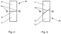
- Fig. 4 shows an upper 6 and a lower 7 segment of a rod 46 connected by a butt joint 8. If clamping ridges 18 apply on the connecting plane, they will apply a load to the weld seam of joint 8 from both sides.
- Fig. 5 shows an upper 11 and a lower 12 segment of an obliquely connected rod. Clamping ridges 18 apply on one side of the weld seam 13 at the most.
- a clamping device comprises ridges 18 located in one and the same clamping plane and if these ridges apply in a connecting plane 8 that is orthogonal to the rod axis, they will penetrate into the connecting plane from both clamping sides. In the case of a bonded joint or a weld seam, a critical splitting force may result.
- a clamping device comprises ridges 18 located in one and the same clamping plane and if these ridges apply to an oblique connecting plane 13, only one ridge 18 may apply a load to the connection on one clamping side, and no force is exerted on other sections of the connection plane 13. Moreover, the clamping does not act in the oblique connecting plane and thus has no direct splitting or cleaving effect either.
- connection method allows connecting rod segments with large differences in longitudinal or transversal stiffness.
- the rod segments have to be dry.
- these have to be rehydrated after their connection and delivered in a preferably saturated condition.
Landscapes
- Health & Medical Sciences (AREA)
- Orthopedic Medicine & Surgery (AREA)
- Life Sciences & Earth Sciences (AREA)
- Neurology (AREA)
- Surgery (AREA)
- Heart & Thoracic Surgery (AREA)
- Engineering & Computer Science (AREA)
- Biomedical Technology (AREA)
- Nuclear Medicine, Radiotherapy & Molecular Imaging (AREA)
- Medical Informatics (AREA)
- Molecular Biology (AREA)
- Animal Behavior & Ethology (AREA)
- General Health & Medical Sciences (AREA)
- Public Health (AREA)
- Veterinary Medicine (AREA)
- Surgical Instruments (AREA)
- Prostheses (AREA)
Description
- The present invention relates to an elastic connecting rod for surgical treatment of the spine, the rod having different degrees of stiffness along its longitudinal axis according to the preamble of
claim 1. - Elastic connecting rods are typically used in conjunction with pedicle screws for the dynamic stabilization of the spine. If such a rod can be provided with a section of higher stiffness, the possible indications can be substantially extended. Thus, a section of higher stiffness may be used for the fusion of vertebral bodies while a section of lower stiffness may be used for the elastic connection of a neighboring vertebral body.
- Today, the "golden standard" in spinal surgery still consists in the fusion (stiffening) of pathologic vertebral bodies. However, fusions often lead to premature degeneration of the segments adjacent to the fusion. Therefore, attempts are being made to provide rods having different degrees of stiffness and to include neighboring segments in the surgical treatment.
- The approaches of the prior art to solving this problem will be set forth below.
- The invention according to patent application
US 2008/0319486 discloses a connecting element having a variable stiffness along its longitudinal axis. The variable stiffness is limited to the sections between two anchoring elements and provides a different response to pressure only. - The invention according to
EP 2 113 216 - The invention according to patent application
US 2008/0177388 also connects different rod materials, but this is achieved according to the male/female principle, which is demanding with regard to the production technique. - The invention according to patent application
US 2009/0248083 also provides sections of different stiffness, however with a varying core that is difficult to anchor particularly in the stiffer areas. - The invention according to patent application
WO 97/32533 - The invention according to patent application
US 2008/0306536 aims to achieve a variable stiffness between vertebral bodies by connecting the connecting element to the bone screw with variable stiffness. This solution is space-consuming and may have unfavorable consequences for the patient. - The invention according to patent application
WO 2007/038429 also allows achieving different degrees of stiffness due to a modular construction but, according to the claims, only in response to bending stresses and not to tensile and compression loads. - The invention according to patent application
US 2005/0203513 also provides different degrees of stiffness in that for one part, the core inside a cylindrical wall varies or, for the other part, the stiffness of a connecting element is locally reduced by material removal. On one hand, this entails the difficulty of anchoring a core by means of a wall of a different kind, and on the other hand, the difficulty of sections of predetermined length, which in the case of multisegment treatments involves significant logistic complexity. - The invention according to patent application
US 2007/0129729 also provides a stiff and an elastic rod portion whose connection is interpenetrating and is supported by a cable. - The invention according to patent application
US 2006/0041259 provides a variable stiffness along its rod axis. The variation is achieved by a helical slot (or spiral slot) reflecting the mechanical principle of a spiral spring. The spring may also be filled with a core and such core may be secured to the spring by welding or bonding. The variation may further be achieved by assembling rods of different properties one behind the other. However, the patent application does not disclose any method of sequentially connecting one rod to the other. Nor does it disclose how the anchorage of the rod in a bone screw would interface with such a connection site. - The inventions according to the patent applications
CH 702636 US 2006/0095134 disclose only blunt connections (butt joint connections) or blunt transitions. - Thus it follows from the prior art that most connections are butt joints, at least peripherally, and thus extend in a plane parallel to the clamping plane in the screw head.
- Accordingly, it is the object of the invention described hereinafter to provide a biocompatible plastic rod having at least two sections of different stiffness along its longitudinal axis.
- This object is achieved in that rod segments having different degrees of stiffness are interconnected in a plane that is oblique to the longitudinal rod axis. The connection may be achieved by bonding or welding or by a combination of both. In the case of welding, especially heating techniques (e.g. plates or mirrors), motion techniques (e.g. vibration or ultrasonic welding), or a combination of both may be contemplated.
- Such a rod of variable stiffness is defined in
claim 1. The further claims define preferred embodiments. - In contrast to
US 2006/0041259 , the present invention discloses a connection of different rods along an inclined plane, in order to not only have normal loads across the connection site, i.e. perpendicular to the connection plane, but also shear loads. The present invention discloses rods with plain sections and connection areas extending over the entire cross section. The inclination angle of the inclined plane is determined in order to avoid an anchorage which clamps from two opposite sides across the connection plane. - Furthermore, it is avoided that a connecting plane coincides with a clamping plane and the connection, besides normal stresses, is also ensured by more suitable shear stresses.
- The present invention is explained in more detail hereinafter by way of preferred examples with reference to drawings which merely illustrate exemplary embodiments and in particular do not show the maximum number of different consecutive degrees of stiffness.
- The Figures schematically show:
-
Fig. 1a : a point-symmetrical rod having sections of different degrees of stiffness connected via an oblique plane; -
Fig. 1b : a rod having an arbitrary cross-section (e.g. with two plane-parallel sides) and sections of different degrees of stiffness connected via an oblique plane; -
Fig. 2a and 2b : the reaction forces for a rod connected by a butt-joint; -
Fig. 3a and 3b : the reaction forces for an oblique connection according to the invention and the angle α of the connecting plane; -
Fig. 4 : clamping ridges on a butt joint; and -
Fig. 5 : clamping ridges on an oblique connection. -
Fig. 1a shows a left 1 and a right 2 segment of arod 41 having a point-symmetrical cross-section 4 and theoblique weld seam 3 connecting them. -
Fig. 1b shows a left 1 and a right 2 segment of arod 42 having anarbitrary cross-section 5, e.g. with two plane-parallel sides, and theoblique weld seam 3 connecting them. -
Figs. 2a and 2b show an upper 6 and a lower 7 segment of arod 44 connected by abutt joint 8 according to the prior art. InFig. 2b ,arrow 9 represents the external force and arrow 10 the reaction force in a sectional view. Here the reaction force exclusively consists of a normal force according toarrow 10. - In contrast,
Figs. 3a and 3b show an upper 11 and a lower 12 segment ofrod 46 interconnected by anoblique joint 13. InFig. 3b ,arrow 14 represents the external force and arrow 15 the reaction forces in a sectional view. Here the reaction forces consist of anormal force 15a and of ashear force 15b. The angle α denotes the angle between the plane of the joint 13 and thelongitudinal axis 47 ofrod 46, or, as illustrated, the side face ofrod 46. -
Fig. 4 shows an upper 6 and a lower 7 segment of arod 46 connected by abutt joint 8. If clampingridges 18 apply on the connecting plane, they will apply a load to the weld seam of joint 8 from both sides. -
Fig. 5 shows an upper 11 and a lower 12 segment of an obliquely connected rod. Clampingridges 18 apply on one side of theweld seam 13 at the most. - Consequently, the disclosed invention offers multiple advantages, as explained below.
- An
oblique connection 13 with an angle of inclination α between 5° and 85°, preferably 45°, always represents a larger surface than a connection that is perpendicular to therod axis 47. In this manner, tensions in the connection are reduced. Furthermore, shear stresses result, which are generally more suitable for connections than normal stresses i.e. stress perpendicular to the connecting plane. - If a clamping device comprises
ridges 18 located in one and the same clamping plane and if these ridges apply in a connectingplane 8 that is orthogonal to the rod axis, they will penetrate into the connecting plane from both clamping sides. In the case of a bonded joint or a weld seam, a critical splitting force may result. - If a clamping device comprises
ridges 18 located in one and the same clamping plane and if these ridges apply to anoblique connecting plane 13, only oneridge 18 may apply a load to the connection on one clamping side, and no force is exerted on other sections of theconnection plane 13. Moreover, the clamping does not act in the oblique connecting plane and thus has no direct splitting or cleaving effect either. - This connection method allows connecting rod segments with large differences in longitudinal or transversal stiffness. To this end, the rod segments have to be dry. In order to allow the subsequent clinical application of rod segments of high stiffness, these have to be rehydrated after their connection and delivered in a preferably saturated condition.
- The description of the examples enables the one skilled in the art to perceive modifications and alternations without leaving the scope of protection defined by the claims.
Claims (9)
- Plastic connecting rod (41, 42, 46) for the surgical treatment of the spine, composed of at least two rod segments (1, 2; 11, 12) having different stiffness properties, characterized in that the rod segments are interconnected along a respective plane (13) oblique with respect to a longitudinal axis (47) of the rod.
- Plastic rod (41, 42, 46) according to claim 1, characterized in that the oblique plane forms an angle in the range 5° to 85° with the longitudinal axis (47) of the rod.
- Plastic rod (41, 42, 46) according to claim 2, characterized in that the oblique plane forms an angle of about 45° with the longitudinal axis (47) of the rod.
- Plastic rod (41, 42, 46) according to one of claims 1 to 3, characterized in that the connection (3, 13) is welded.
- Plastic rod (41, 42, 46) according one of claims 1 to 3, characterized in that the connection (3, 13) is bonded.
- Plastic rod (41, 42, 46) according to one of claims 1 to 3, characterized in that the connection (3, 13)is achieved by a combination of welding and bonding.
- Plastic rod (41, 42, 46) according to any one of claims 1 to 6, characterized in that the number of different plastic materials of the rod is limited to two.
- Plastic rod (41, 42, 46) according to any one of claims 1 to 7, characterized in that the plastic material is a polycarbonate urethane.
- Plastic rod (41, 42, 46) according to any one of claims 1 to 8, characterized in that the connected rod segments (1, 2; 11, 12) are rehydrated after their connection.
Applications Claiming Priority (2)
| Application Number | Priority Date | Filing Date | Title |
|---|---|---|---|
| CH10482012 | 2012-07-05 | ||
| PCT/CH2013/000112 WO2014005236A1 (en) | 2012-07-05 | 2013-06-24 | Elastic rod having different degrees of stiffness for the surgical treatment of the spine |
Publications (2)
| Publication Number | Publication Date |
|---|---|
| EP2869773A1 EP2869773A1 (en) | 2015-05-13 |
| EP2869773B1 true EP2869773B1 (en) | 2018-12-19 |
Family
ID=46762758
Family Applications (1)
| Application Number | Title | Priority Date | Filing Date |
|---|---|---|---|
| EP13734955.1A Active EP2869773B1 (en) | 2012-07-05 | 2013-06-24 | Elastic rod having different degrees of stiffness for the surgical treatment of the spine |
Country Status (3)
| Country | Link |
|---|---|
| US (1) | US10695097B2 (en) |
| EP (1) | EP2869773B1 (en) |
| WO (1) | WO2014005236A1 (en) |
Cited By (1)
| Publication number | Priority date | Publication date | Assignee | Title |
|---|---|---|---|---|
| WO2024100147A1 (en) | 2022-11-08 | 2024-05-16 | Spinesave Ag | Load-carrying rod |
Family Cites Families (77)
| Publication number | Priority date | Publication date | Assignee | Title |
|---|---|---|---|---|
| US5215246A (en) * | 1991-12-31 | 1993-06-01 | Southwire Company | Method and apparatus for brazing |
| US5217461A (en) * | 1992-02-20 | 1993-06-08 | Acromed Corporation | Apparatus for maintaining vertebrae in a desired spatial relationship |
| US5593408A (en) * | 1994-11-30 | 1997-01-14 | Sofamor S.N.C | Vertebral instrumentation rod |
| FR2745707B1 (en) | 1996-03-05 | 1998-04-30 | Neurofix | SPINAL OSTEOSYNTHESIS DEVICE |
| FR2763831B1 (en) * | 1997-05-29 | 1999-08-06 | Materiel Orthopedique En Abreg | VERTEBRAL ROD OF CONSTANT SECTION FOR RACHIDIAN OSTEOSYNTHESIS INSTRUMENTATIONS |
| US6197015B1 (en) * | 1998-12-09 | 2001-03-06 | Medi-Dyne Inc. | Angiography catheter with sections having different mechanical properties |
| US6966910B2 (en) * | 2002-04-05 | 2005-11-22 | Stephen Ritland | Dynamic fixation device and method of use |
| JP4559848B2 (en) * | 2002-05-08 | 2010-10-13 | リトランド,ステイーヴン | Dynamic fixing device and use thereof |
| CN100393504C (en) * | 2003-03-06 | 2008-06-11 | 维斯塔斯风力系统公司 | Connection between composite materials with incompatible features and method of preparation |
| JP5078355B2 (en) | 2003-05-23 | 2012-11-21 | グローバス メディカル インコーポレイティッド | Spine stabilization system |
| US20050203513A1 (en) | 2003-09-24 | 2005-09-15 | Tae-Ahn Jahng | Spinal stabilization device |
| FR2867057B1 (en) * | 2004-03-02 | 2007-06-01 | Spinevision | DYNAMIC BONDING ELEMENT FOR A SPINAL FIXING SYSTEM AND FIXING SYSTEM COMPRISING SUCH A CONNECTING MEMBER |
| US7766941B2 (en) * | 2004-05-14 | 2010-08-03 | Paul Kamaljit S | Spinal support, stabilization |
| US20060095134A1 (en) | 2004-10-28 | 2006-05-04 | Sdgi Holdings, Inc. | Materials, devices and methods for implantation of transformable implants |
| US8267967B2 (en) * | 2004-12-15 | 2012-09-18 | Stryker Spine | Methods and apparatus for modular and variable spinal fixation |
| US20060242813A1 (en) * | 2005-04-29 | 2006-11-02 | Fred Molz | Metal injection molding of spinal fixation systems components |
| US20060247638A1 (en) * | 2005-04-29 | 2006-11-02 | Sdgi Holdings, Inc. | Composite spinal fixation systems |
| US7828825B2 (en) * | 2005-06-20 | 2010-11-09 | Warsaw Orthopedic, Inc. | Multi-level multi-functional spinal stabilization systems and methods |
| WO2007038429A1 (en) | 2005-09-27 | 2007-04-05 | Endius, Inc. | Methods and apparatuses for stabilizing the spine through an access device |
| US8105368B2 (en) * | 2005-09-30 | 2012-01-31 | Jackson Roger P | Dynamic stabilization connecting member with slitted core and outer sleeve |
| US8641735B2 (en) * | 2006-01-27 | 2014-02-04 | Warsaw Orthopedic, Inc. | Implantable longitudinal orthopedic supports for accommodating multiple anatomical support requirements |
| US7815663B2 (en) * | 2006-01-27 | 2010-10-19 | Warsaw Orthopedic, Inc. | Vertebral rods and methods of use |
| US20070191841A1 (en) * | 2006-01-27 | 2007-08-16 | Sdgi Holdings, Inc. | Spinal rods having different flexural rigidities about different axes and methods of use |
| US20070233073A1 (en) * | 2006-03-02 | 2007-10-04 | Sdgi Holdings, Inc. | Spinal rod characterized by a time-varying stiffness |
| US7563274B2 (en) * | 2006-04-25 | 2009-07-21 | Warsaw Orthopedic, Inc. | Surgical instruments and techniques for controlling spinal motion segments with positioning of spinal stabilization elements |
| DE602006016407D1 (en) * | 2006-05-16 | 2010-10-07 | Biedermann Motech Gmbh | Longitudinal part for spine or trauma surgery |
| US7766942B2 (en) * | 2006-08-31 | 2010-08-03 | Warsaw Orthopedic, Inc. | Polymer rods for spinal applications |
| US7824430B2 (en) * | 2006-12-08 | 2010-11-02 | Warsaw Orthopedic, Inc. | Methods and devices for treating a multi-level spinal deformity |
| FR2910267B1 (en) * | 2006-12-21 | 2009-01-23 | Ldr Medical Soc Par Actions Si | VERTEBRAL SUPPORT DEVICE |
| US7875059B2 (en) * | 2007-01-18 | 2011-01-25 | Warsaw Orthopedic, Inc. | Variable stiffness support members |
| WO2008100590A1 (en) * | 2007-02-14 | 2008-08-21 | Flex Technology Inc | Flexible spine components |
| EP1972289B1 (en) * | 2007-03-23 | 2018-10-17 | coLigne AG | Elongated stabilization member and bone anchor useful in bone and especially spinal repair processes |
| US20100126654A1 (en) * | 2007-03-30 | 2010-05-27 | Atsushi Katayama | Working apparatus, apparatus for applying adhesive tape, and tape member adding method |
| US8043333B2 (en) | 2007-06-08 | 2011-10-25 | Synthes Usa, Llc | Dynamic stabilization system |
| US20080312694A1 (en) * | 2007-06-15 | 2008-12-18 | Peterman Marc M | Dynamic stabilization rod for spinal implants and methods for manufacturing the same |
| US8292925B2 (en) * | 2007-06-19 | 2012-10-23 | Zimmer Spine, Inc. | Flexible member with variable flexibility for providing dynamic stability to a spine |
| US8353935B2 (en) * | 2008-02-14 | 2013-01-15 | Krause William R | Flexible spine components having a concentric slot |
| US20090240284A1 (en) * | 2008-03-24 | 2009-09-24 | David Scott Randol | Stabilization rods |
| US20090248083A1 (en) * | 2008-03-26 | 2009-10-01 | Warsaw Orthopedic, Inc. | Elongated connecting element with varying modulus of elasticity |
| US20090248077A1 (en) * | 2008-03-31 | 2009-10-01 | Derrick William Johns | Hybrid dynamic stabilization |
| EP2113216B1 (en) | 2008-04-28 | 2012-05-30 | Biedermann Technologies GmbH & Co. KG | Rod-shaped element for spinal stabilization and method for producing the same |
| JP5608642B2 (en) * | 2008-05-13 | 2014-10-15 | ストライカー・スピン | Composite spinal rod |
| EP2468201B1 (en) * | 2008-08-12 | 2014-10-08 | Biedermann Technologies GmbH & Co. KG | Flexible stabilization device including a rod and tool for manufacturing the rod |
| JP4937215B2 (en) * | 2008-09-01 | 2012-05-23 | 三菱電機株式会社 | Connection method for thermoplastic resin elongate body |
| US20100114167A1 (en) * | 2008-10-31 | 2010-05-06 | Warsaw Orthopedic, Inc. | Transition rod |
| US20100114165A1 (en) * | 2008-11-04 | 2010-05-06 | Abbott Spine, Inc. | Posterior dynamic stabilization system with pivoting collars |
| CN102325508A (en) * | 2009-02-19 | 2012-01-18 | 安东·E·鲍登 | Compliant Dynamic Spinal Implant |
| US8394124B2 (en) * | 2009-06-18 | 2013-03-12 | The University Of Toledo | Unidirectional rotatory pedicle screw and spinal deformity correction device for correction of spinal deformity in growing children |
| SE0900861A1 (en) * | 2009-06-24 | 2010-12-25 | Tetra Laval Holdings & Finance | Splice of strips |
| US20110029018A1 (en) * | 2009-07-30 | 2011-02-03 | Warsaw Othropedic, Inc | Variable resistance spinal stablization systems and methods |
| US8657856B2 (en) * | 2009-08-28 | 2014-02-25 | Pioneer Surgical Technology, Inc. | Size transition spinal rod |
| US20110106162A1 (en) * | 2009-10-30 | 2011-05-05 | Warsaw Orthopedic, Inc. | Composite Connecting Elements for Spinal Stabilization Systems |
| US20110152936A1 (en) * | 2009-12-21 | 2011-06-23 | Warsaw Orthopedic, Inc. | Directional vertebral rod |
| US20110152937A1 (en) * | 2009-12-22 | 2011-06-23 | Warsaw Orthopedic, Inc. | Surgical Implants for Selectively Controlling Spinal Motion Segments |
| CH702637A1 (en) * | 2010-02-04 | 2011-08-15 | Spinesave Ag | Pre-bent biocompatible plastic rod for surgical stabilization of spinal column of patient, is bent in supply condition along longitudinal axis by thermal plasticity after annealing process and by injection molding process |
| CH702636A1 (en) * | 2010-02-04 | 2011-08-15 | Spinesave Ag | Point-symmetric plastic rod for surgical treatment of spinal column to dynamically stabilize spinal column, has two regions with different rigidities in longitudinal direction and connected with each other by adhesives, welds or combination |
| CH703000A2 (en) * | 2010-04-29 | 2011-10-31 | Spinesave Ag | Flexible plastic connecting rod for surgical treatment of spinal column, consists of two different radii of curvatures that lie between specific range, where longitudinal axis of rod runs in shape of curve |
| CH703411A2 (en) * | 2010-07-12 | 2012-01-13 | Spinelab Ag | Spinal implant with pedicle screws and the corresponding pedicle screw. |
| NO2608728T3 (en) * | 2010-08-26 | 2018-03-24 | ||
| JP2013540468A (en) * | 2010-09-08 | 2013-11-07 | ロジャー・ピー・ジャクソン | Dynamic fixing member having an elastic part and an inelastic part |
| US20120065687A1 (en) * | 2010-09-10 | 2012-03-15 | Warsaw Orthopedic, Inc. | Multi-Radius Vertebral Rod With a Varying Stiffness |
| DE102010060101A1 (en) * | 2010-09-20 | 2012-03-22 | Aesculap Ag | Spinal stabilization system and surgical device for temporarily stiffening a flexible intermediate portion of a spinal stabilization system connector |
| US20120290013A1 (en) * | 2011-03-24 | 2012-11-15 | Peter Melott Simonson | Tapered spinal rod |
| US20130079825A1 (en) * | 2011-09-26 | 2013-03-28 | Warsaw Orthopedic, Inc. | Template for multiple length spinal rods |
| US20130103090A1 (en) * | 2011-10-25 | 2013-04-25 | Warsaw Orthopedic, Inc. | Vertebral rod system and methods of use |
| US20130110169A1 (en) * | 2011-10-26 | 2013-05-02 | Warsaw Orthopedic, Inc. | Vertebral rod system and methods of use |
| US20140025116A1 (en) * | 2012-07-23 | 2014-01-23 | Chih-Hsuan Wei | Fixing Structure of Bone Screws and a Connecting Rod for a Minimally Invasive Surgery |
| US20150305779A1 (en) * | 2012-08-21 | 2015-10-29 | Pierre M. Montavon | Spring and device for stabilizing human or animal bone |
| US20140081333A1 (en) * | 2012-09-17 | 2014-03-20 | Roger P. Jackson | Dynamic stabilization medical implant assembles and methods |
| US9757158B2 (en) * | 2012-12-06 | 2017-09-12 | In Queue Innovations, Llc | Minimally invasive spinal column realignment system and method |
| US9101400B2 (en) * | 2013-03-07 | 2015-08-11 | Warsaw Orthopedic, Inc. | Rotational offset oval vertebral rod |
| US10786283B2 (en) * | 2013-08-01 | 2020-09-29 | Musc Foundation For Research Development | Skeletal bone fixation mechanism |
| DE102013110173A1 (en) * | 2013-09-16 | 2015-03-19 | Aesculap Ag | Connecting element and spine stabilization system |
| US20150297265A1 (en) * | 2014-04-22 | 2015-10-22 | Alan J. Arena | Remote Operated Adjustable Spine Device |
| US10973557B2 (en) * | 2015-10-15 | 2021-04-13 | Seth K. WILLIAMS | Spinal rod implant extension |
| US10194953B2 (en) * | 2015-10-15 | 2019-02-05 | Seth K. WILLIAMS | Spinal rod implant extension |
| US10639078B2 (en) * | 2015-11-17 | 2020-05-05 | Warsaw Orthopedic, Inc. | Spinal implant system and method |
-
2013
- 2013-06-24 US US14/408,247 patent/US10695097B2/en active Active
- 2013-06-24 WO PCT/CH2013/000112 patent/WO2014005236A1/en not_active Ceased
- 2013-06-24 EP EP13734955.1A patent/EP2869773B1/en active Active
Non-Patent Citations (1)
| Title |
|---|
| None * |
Cited By (1)
| Publication number | Priority date | Publication date | Assignee | Title |
|---|---|---|---|---|
| WO2024100147A1 (en) | 2022-11-08 | 2024-05-16 | Spinesave Ag | Load-carrying rod |
Also Published As
| Publication number | Publication date |
|---|---|
| US10695097B2 (en) | 2020-06-30 |
| WO2014005236A1 (en) | 2014-01-09 |
| EP2869773A1 (en) | 2015-05-13 |
| US20150173799A1 (en) | 2015-06-25 |
Similar Documents
| Publication | Publication Date | Title |
|---|---|---|
| JP7186682B2 (en) | Devices and methods of use for bone stabilization and stretching | |
| US20220168017A1 (en) | Dynamic spinal stabilization with rod-cord longitudinal connecting members | |
| ES2307171T3 (en) | ELEMENT OF DYNAMIC UNION FOR A RAQUIDEA FIXING SYSTEM AND FIXING SYSTEM THAT INCLUDES SUCH UNION ELEMENT. | |
| JP4588294B2 (en) | Fixation device for fixing bones, especially vertebral bodies relative to each other | |
| EP2113216B1 (en) | Rod-shaped element for spinal stabilization and method for producing the same | |
| KR101150539B1 (en) | Spinal stabilization system | |
| US8012177B2 (en) | Dynamic stabilization assembly with frusto-conical connection | |
| US9011497B2 (en) | Bone anchoring system | |
| CN101835435B (en) | Bone plates and bone plate assemblies | |
| ES2503727T3 (en) | Device to produce an anchor in human or animal tissue | |
| JP2003339726A (en) | Spine implant | |
| CN101466320A (en) | Dynamic spinal stabilization device with dampener | |
| CA2587439A1 (en) | Devices for introduction into a body via a substantially straight conduit to form a predefined curved configuration, and methods employing such devices | |
| US20070233064A1 (en) | Apparatus and method for flexible spinal fixation | |
| US20130123854A1 (en) | System and method for spinal stabilization through mutli-head spinal screws | |
| US20120184993A1 (en) | Expandable facet screw | |
| US20090275985A1 (en) | Dynamic stabilization assembly having pre-compressed spacers with differential displacements | |
| CN101384224A (en) | Back Adjustable Spinal Connector Assembly | |
| KR20080078553A (en) | Stabilizers for stabilizing vertebral bones and rod connectors used in them | |
| CN101460108A (en) | Device for interconnecting components in a spinal implant assembly | |
| EP2280666A2 (en) | Intervertebral prostheses with compliant filler material for supporting adjacent vertebral bodies and method | |
| US20130158606A1 (en) | Spinal implant set for the dynamic stabilization of the spine | |
| CN100435747C (en) | Connecting rod for bone connecting element | |
| US11000326B1 (en) | Orthopedic fastener and associated systems and methods | |
| US10695097B2 (en) | Elastic rod having different degrees of stiffness for the surgical treatment of the spine |
Legal Events
| Date | Code | Title | Description |
|---|---|---|---|
| PUAI | Public reference made under article 153(3) epc to a published international application that has entered the european phase |
Free format text: ORIGINAL CODE: 0009012 |
|
| 17P | Request for examination filed |
Effective date: 20150128 |
|
| AK | Designated contracting states |
Kind code of ref document: A1 Designated state(s): AL AT BE BG CH CY CZ DE DK EE ES FI FR GB GR HR HU IE IS IT LI LT LU LV MC MK MT NL NO PL PT RO RS SE SI SK SM TR |
|
| AX | Request for extension of the european patent |
Extension state: BA ME |
|
| DAX | Request for extension of the european patent (deleted) | ||
| GRAP | Despatch of communication of intention to grant a patent |
Free format text: ORIGINAL CODE: EPIDOSNIGR1 |
|
| STAA | Information on the status of an ep patent application or granted ep patent |
Free format text: STATUS: GRANT OF PATENT IS INTENDED |
|
| INTG | Intention to grant announced |
Effective date: 20180709 |
|
| GRAS | Grant fee paid |
Free format text: ORIGINAL CODE: EPIDOSNIGR3 |
|
| GRAA | (expected) grant |
Free format text: ORIGINAL CODE: 0009210 |
|
| STAA | Information on the status of an ep patent application or granted ep patent |
Free format text: STATUS: THE PATENT HAS BEEN GRANTED |
|
| AK | Designated contracting states |
Kind code of ref document: B1 Designated state(s): AL AT BE BG CH CY CZ DE DK EE ES FI FR GB GR HR HU IE IS IT LI LT LU LV MC MK MT NL NO PL PT RO RS SE SI SK SM TR |
|
| REG | Reference to a national code |
Ref country code: GB Ref legal event code: FG4D |
|
| REG | Reference to a national code |
Ref country code: CH Ref legal event code: EP |
|
| REG | Reference to a national code |
Ref country code: DE Ref legal event code: R096 Ref document number: 602013048424 Country of ref document: DE |
|
| REG | Reference to a national code |
Ref country code: IE Ref legal event code: FG4D |
|
| REG | Reference to a national code |
Ref country code: AT Ref legal event code: REF Ref document number: 1077840 Country of ref document: AT Kind code of ref document: T Effective date: 20190115 |
|
| REG | Reference to a national code |
Ref country code: NL Ref legal event code: MP Effective date: 20181219 |
|
| PG25 | Lapsed in a contracting state [announced via postgrant information from national office to epo] |
Ref country code: HR Free format text: LAPSE BECAUSE OF FAILURE TO SUBMIT A TRANSLATION OF THE DESCRIPTION OR TO PAY THE FEE WITHIN THE PRESCRIBED TIME-LIMIT Effective date: 20181219 Ref country code: LT Free format text: LAPSE BECAUSE OF FAILURE TO SUBMIT A TRANSLATION OF THE DESCRIPTION OR TO PAY THE FEE WITHIN THE PRESCRIBED TIME-LIMIT Effective date: 20181219 Ref country code: LV Free format text: LAPSE BECAUSE OF FAILURE TO SUBMIT A TRANSLATION OF THE DESCRIPTION OR TO PAY THE FEE WITHIN THE PRESCRIBED TIME-LIMIT Effective date: 20181219 Ref country code: NO Free format text: LAPSE BECAUSE OF FAILURE TO SUBMIT A TRANSLATION OF THE DESCRIPTION OR TO PAY THE FEE WITHIN THE PRESCRIBED TIME-LIMIT Effective date: 20190319 Ref country code: FI Free format text: LAPSE BECAUSE OF FAILURE TO SUBMIT A TRANSLATION OF THE DESCRIPTION OR TO PAY THE FEE WITHIN THE PRESCRIBED TIME-LIMIT Effective date: 20181219 Ref country code: BG Free format text: LAPSE BECAUSE OF FAILURE TO SUBMIT A TRANSLATION OF THE DESCRIPTION OR TO PAY THE FEE WITHIN THE PRESCRIBED TIME-LIMIT Effective date: 20190319 |
|
| REG | Reference to a national code |
Ref country code: LT Ref legal event code: MG4D |
|
| REG | Reference to a national code |
Ref country code: AT Ref legal event code: MK05 Ref document number: 1077840 Country of ref document: AT Kind code of ref document: T Effective date: 20181219 |
|
| PG25 | Lapsed in a contracting state [announced via postgrant information from national office to epo] |
Ref country code: GR Free format text: LAPSE BECAUSE OF FAILURE TO SUBMIT A TRANSLATION OF THE DESCRIPTION OR TO PAY THE FEE WITHIN THE PRESCRIBED TIME-LIMIT Effective date: 20190320 Ref country code: AL Free format text: LAPSE BECAUSE OF FAILURE TO SUBMIT A TRANSLATION OF THE DESCRIPTION OR TO PAY THE FEE WITHIN THE PRESCRIBED TIME-LIMIT Effective date: 20181219 Ref country code: SE Free format text: LAPSE BECAUSE OF FAILURE TO SUBMIT A TRANSLATION OF THE DESCRIPTION OR TO PAY THE FEE WITHIN THE PRESCRIBED TIME-LIMIT Effective date: 20181219 Ref country code: RS Free format text: LAPSE BECAUSE OF FAILURE TO SUBMIT A TRANSLATION OF THE DESCRIPTION OR TO PAY THE FEE WITHIN THE PRESCRIBED TIME-LIMIT Effective date: 20181219 |
|
| PG25 | Lapsed in a contracting state [announced via postgrant information from national office to epo] |
Ref country code: NL Free format text: LAPSE BECAUSE OF FAILURE TO SUBMIT A TRANSLATION OF THE DESCRIPTION OR TO PAY THE FEE WITHIN THE PRESCRIBED TIME-LIMIT Effective date: 20181219 |
|
| PG25 | Lapsed in a contracting state [announced via postgrant information from national office to epo] |
Ref country code: CZ Free format text: LAPSE BECAUSE OF FAILURE TO SUBMIT A TRANSLATION OF THE DESCRIPTION OR TO PAY THE FEE WITHIN THE PRESCRIBED TIME-LIMIT Effective date: 20181219 Ref country code: ES Free format text: LAPSE BECAUSE OF FAILURE TO SUBMIT A TRANSLATION OF THE DESCRIPTION OR TO PAY THE FEE WITHIN THE PRESCRIBED TIME-LIMIT Effective date: 20181219 Ref country code: PL Free format text: LAPSE BECAUSE OF FAILURE TO SUBMIT A TRANSLATION OF THE DESCRIPTION OR TO PAY THE FEE WITHIN THE PRESCRIBED TIME-LIMIT Effective date: 20181219 Ref country code: PT Free format text: LAPSE BECAUSE OF FAILURE TO SUBMIT A TRANSLATION OF THE DESCRIPTION OR TO PAY THE FEE WITHIN THE PRESCRIBED TIME-LIMIT Effective date: 20190419 |
|
| PG25 | Lapsed in a contracting state [announced via postgrant information from national office to epo] |
Ref country code: EE Free format text: LAPSE BECAUSE OF FAILURE TO SUBMIT A TRANSLATION OF THE DESCRIPTION OR TO PAY THE FEE WITHIN THE PRESCRIBED TIME-LIMIT Effective date: 20181219 Ref country code: SM Free format text: LAPSE BECAUSE OF FAILURE TO SUBMIT A TRANSLATION OF THE DESCRIPTION OR TO PAY THE FEE WITHIN THE PRESCRIBED TIME-LIMIT Effective date: 20181219 Ref country code: SK Free format text: LAPSE BECAUSE OF FAILURE TO SUBMIT A TRANSLATION OF THE DESCRIPTION OR TO PAY THE FEE WITHIN THE PRESCRIBED TIME-LIMIT Effective date: 20181219 Ref country code: RO Free format text: LAPSE BECAUSE OF FAILURE TO SUBMIT A TRANSLATION OF THE DESCRIPTION OR TO PAY THE FEE WITHIN THE PRESCRIBED TIME-LIMIT Effective date: 20181219 Ref country code: IS Free format text: LAPSE BECAUSE OF FAILURE TO SUBMIT A TRANSLATION OF THE DESCRIPTION OR TO PAY THE FEE WITHIN THE PRESCRIBED TIME-LIMIT Effective date: 20190419 |
|
| REG | Reference to a national code |
Ref country code: DE Ref legal event code: R097 Ref document number: 602013048424 Country of ref document: DE |
|
| PLBE | No opposition filed within time limit |
Free format text: ORIGINAL CODE: 0009261 |
|
| STAA | Information on the status of an ep patent application or granted ep patent |
Free format text: STATUS: NO OPPOSITION FILED WITHIN TIME LIMIT |
|
| PG25 | Lapsed in a contracting state [announced via postgrant information from national office to epo] |
Ref country code: AT Free format text: LAPSE BECAUSE OF FAILURE TO SUBMIT A TRANSLATION OF THE DESCRIPTION OR TO PAY THE FEE WITHIN THE PRESCRIBED TIME-LIMIT Effective date: 20181219 Ref country code: DK Free format text: LAPSE BECAUSE OF FAILURE TO SUBMIT A TRANSLATION OF THE DESCRIPTION OR TO PAY THE FEE WITHIN THE PRESCRIBED TIME-LIMIT Effective date: 20181219 |
|
| 26N | No opposition filed |
Effective date: 20190920 |
|
| PG25 | Lapsed in a contracting state [announced via postgrant information from national office to epo] |
Ref country code: MC Free format text: LAPSE BECAUSE OF FAILURE TO SUBMIT A TRANSLATION OF THE DESCRIPTION OR TO PAY THE FEE WITHIN THE PRESCRIBED TIME-LIMIT Effective date: 20181219 |
|
| PG25 | Lapsed in a contracting state [announced via postgrant information from national office to epo] |
Ref country code: SI Free format text: LAPSE BECAUSE OF FAILURE TO SUBMIT A TRANSLATION OF THE DESCRIPTION OR TO PAY THE FEE WITHIN THE PRESCRIBED TIME-LIMIT Effective date: 20181219 |
|
| REG | Reference to a national code |
Ref country code: BE Ref legal event code: MM Effective date: 20190630 |
|
| PG25 | Lapsed in a contracting state [announced via postgrant information from national office to epo] |
Ref country code: TR Free format text: LAPSE BECAUSE OF FAILURE TO SUBMIT A TRANSLATION OF THE DESCRIPTION OR TO PAY THE FEE WITHIN THE PRESCRIBED TIME-LIMIT Effective date: 20181219 |
|
| PG25 | Lapsed in a contracting state [announced via postgrant information from national office to epo] |
Ref country code: IE Free format text: LAPSE BECAUSE OF NON-PAYMENT OF DUE FEES Effective date: 20190624 |
|
| PG25 | Lapsed in a contracting state [announced via postgrant information from national office to epo] |
Ref country code: LU Free format text: LAPSE BECAUSE OF NON-PAYMENT OF DUE FEES Effective date: 20190624 Ref country code: BE Free format text: LAPSE BECAUSE OF NON-PAYMENT OF DUE FEES Effective date: 20190630 |
|
| PG25 | Lapsed in a contracting state [announced via postgrant information from national office to epo] |
Ref country code: CY Free format text: LAPSE BECAUSE OF FAILURE TO SUBMIT A TRANSLATION OF THE DESCRIPTION OR TO PAY THE FEE WITHIN THE PRESCRIBED TIME-LIMIT Effective date: 20181219 |
|
| PG25 | Lapsed in a contracting state [announced via postgrant information from national office to epo] |
Ref country code: MT Free format text: LAPSE BECAUSE OF FAILURE TO SUBMIT A TRANSLATION OF THE DESCRIPTION OR TO PAY THE FEE WITHIN THE PRESCRIBED TIME-LIMIT Effective date: 20181219 Ref country code: HU Free format text: LAPSE BECAUSE OF FAILURE TO SUBMIT A TRANSLATION OF THE DESCRIPTION OR TO PAY THE FEE WITHIN THE PRESCRIBED TIME-LIMIT; INVALID AB INITIO Effective date: 20130624 |
|
| PG25 | Lapsed in a contracting state [announced via postgrant information from national office to epo] |
Ref country code: MK Free format text: LAPSE BECAUSE OF FAILURE TO SUBMIT A TRANSLATION OF THE DESCRIPTION OR TO PAY THE FEE WITHIN THE PRESCRIBED TIME-LIMIT Effective date: 20181219 |
|
| P01 | Opt-out of the competence of the unified patent court (upc) registered |
Effective date: 20230512 |
|
| PGFP | Annual fee paid to national office [announced via postgrant information from national office to epo] |
Ref country code: DE Payment date: 20250618 Year of fee payment: 13 |
|
| PGFP | Annual fee paid to national office [announced via postgrant information from national office to epo] |
Ref country code: GB Payment date: 20250618 Year of fee payment: 13 |
|
| PGFP | Annual fee paid to national office [announced via postgrant information from national office to epo] |
Ref country code: FR Payment date: 20250625 Year of fee payment: 13 |
|
| PGFP | Annual fee paid to national office [announced via postgrant information from national office to epo] |
Ref country code: IT Payment date: 20250624 Year of fee payment: 13 |
|
| PGFP | Annual fee paid to national office [announced via postgrant information from national office to epo] |
Ref country code: CH Payment date: 20250701 Year of fee payment: 13 |