EP2869667B1 - Microwave oven - Google Patents
Microwave oven Download PDFInfo
- Publication number
- EP2869667B1 EP2869667B1 EP13191105.9A EP13191105A EP2869667B1 EP 2869667 B1 EP2869667 B1 EP 2869667B1 EP 13191105 A EP13191105 A EP 13191105A EP 2869667 B1 EP2869667 B1 EP 2869667B1
- Authority
- EP
- European Patent Office
- Prior art keywords
- suppression
- motor mounting
- muffle
- motor
- mounting element
- Prior art date
- Legal status (The legal status is an assumption and is not a legal conclusion. Google has not performed a legal analysis and makes no representation as to the accuracy of the status listed.)
- Active
Links
Images


Classifications
-
- H—ELECTRICITY
- H05—ELECTRIC TECHNIQUES NOT OTHERWISE PROVIDED FOR
- H05B—ELECTRIC HEATING; ELECTRIC LIGHT SOURCES NOT OTHERWISE PROVIDED FOR; CIRCUIT ARRANGEMENTS FOR ELECTRIC LIGHT SOURCES, IN GENERAL
- H05B6/00—Heating by electric, magnetic or electromagnetic fields
- H05B6/64—Heating using microwaves
- H05B6/76—Prevention of microwave leakage, e.g. door sealings
Definitions
- the present invention relates generally to the field of microwave ovens. More specifically, the present invention is related to leakage suppression for microwave ovens.
- Microwave ovens for preparing food are well known in prior art.
- Sophisticated models comprise a blower or fan in order to obtain air turbulences within the interior of the microwave oven.
- Document DE 41 05 300 A1 discloses a blower for a microwave oven.
- the blower comprises a motor with a rotatable shaft extending through an opening of the oven muffle into the interior of the oven. At the free end of the rotatable shaft a blower wheel is attached.
- the opening matched to the rotatable shaft, the blower wheel, the dish connected with the oven muffle and a carrying plate of the motor form a microwave-proof blocking filter unit.
- the oven is adapted to generate microwaves within a cooking chamber. Furthermore, the oven comprises a rotatable shaft which is passing through an opening of a separator. In order to prevent a microwave passage through said opening, a bush is used which immediately bears against the separator.
- European Patent Application EP 2 247 160 A1 discloses a microwave sealing device for sealing an opening for a rotating shaft.
- a drawback of the known microwave blocking filter unit is that due to the connection of the carrying plate with the oven muffle the suppression capability of the microwave blocking filter unit is decreased. Additionally, the microwave blocking filter unit comprises a complex structure and is therefore cost-intensive in manufacturing.
- the invention relates to a microwave oven comprising an oven muffle, a high-frequency oscillator for generating microwaves propagating within the oven muffle, an opening within a muffle wall of the oven muffle for passing a rotatable shaft of a motor through the muffle wall and means for suppressing microwave leakage through said opening, wherein the means for suppressing microwave leakage are arranged at a distance to the muffle wall by means of a motor mounting element bearing the motor and wherein there is no direct physical contact between the muffle wall and the suppression element, wherein the suppression element comprises a suppression portion to be located in vicinity to the opening and a retaining portion for keeping the suppression portion at a distance to the motor mounting element, wherein the suppression element comprises at least one fastening portion for attaching the suppression element at the motor mounting element, wherein the at least one fastening portion is located at the opposite side of the suppression portion and wherein the suppression portion comprises a disk-like shape.
- the motor mounting element is adapted to bear the motor as well as the suppression means.
- a gap between the motor and the muffle wall used to reduce the heating of the motor if the oven comprises further heating means, e.g. heating coils may be additionally used to receive the suppression means. Due to avoiding a direct physical contact between the muffle wall and the suppression means, the suppression performance is significantly enhanced.
- the motor mounting element comprises a bracket-like shape spanning at least a portion of the outer surface of the oven muffle. Thereby, the gap between the muffle wall and the suppression means for receiving the motor mounting element is achieved.
- the motor mounting element comprises a middle portion to be disposed at a distance from the outer surface of the muffle wall and interconnecting portions for connecting the motor mounting element with the oven muffle.
- a pair of interconnecting portions spaced to each other is used to attach the motor mounting element at the oven muffle.
- Said interconnecting portions may protrude laterally from the middle portion at opposite sides. Thereby, the bracket-like shape of the motor mounting element is obtained.
- the motor and the suppression means are located at different sides of the motor mounting element. Due to the opposite arrangement of the motor and the suppressing means, a single motor mounting element can be used to bear both elements.
- the motor and the suppressing means may be arranged such, that the rotatable shaft of the motor extends through an opening provided within the suppressing means.
- the suppression portion is preferably arranged at a small distance e.g. 1 - 5mm to the muffle wall.
- the suppression portion transforms the wave impedance in the area of the opening of the muffle wall.
- the retaining portion provides a portion for spacing the suppression portion at the desired distance from the muffle wall, respectively, from the motor mounting element.
- the suppression portion is circular formed. Thereby, the radial distance between the opening of the muffle wall and the edge of the suppression portion is identical in all directions.
- the suppression portion may be constituted by a flat, sheet-like material or a corrugated material.
- the retaining portion comprises a bushing-like shape.
- the rotatable shaft of the motor may protrude through an opening of the bushing-like shaped retaining portion.
- the suppression element comprises at least one fastening portion for attaching the suppression element at the motor mounting element.
- the suppression element may be fastened at the motor mounting element independently of the fastening means of the motor, specifically at the opposite side of the motor.
- the at least one fastening portion is located at the opposite side of the suppression portion.
- the fastening portion and the suppression portion are spatially separated in order to increase the suppression leakage performance.
- the suppression element is formed as a one-piece element.
- the suppression means particularly the suppression element are constituted or formed of an electrically conductive material.
- Fig. 1 illustrates an oven muffle 2 of a microwave oven 1.
- the microwave oven 1 comprises a high frequency oscillator (not shown) which is adapted to generate microwaves within the oven muffle 2 in order to heat food arranged within the oven muffle 2.
- the microwave oven 1 further comprises a motor 5 with a rotatable shaft 4, wherein the motor 5 is attached at the oven muffle 2 such, that the rotatable shaft 4 extends through an opening 3 within a muffle wall 2.1 of the oven muffle 2 into the interior cavity of the microwave oven 1.
- the rotatable shaft 4 of the motor 2 may be used to power a blower wheel.
- the rotatable shaft 4 may be used to power a turntable within the cavity of the microwave oven 1.
- the microwave oven 1 comprises a suppression element 6.
- Said suppression element 6 may be located in immediate vicinity of the opening 3. However, there is no direct physical contact between the muffle wall 2.1 of the oven muffle 2 and the suppression element 6.
- the suppression element 6 is kept in place by means of a motor mounting element (not shown in Fig. 1 and Fig. 2 and described in more detail in the following) which additionally supports the motor 5.
- the suppression element 6 is preferably arranged at a distance d to the muffle wall 2.1, wherein the distance d is chosen according to the wavelength of the microwaves generated by the high frequency oscillator in order to provide a microwave-tight gap 8 between the suppression element 6 and the muffle wall 2.1.
- Fig. 3-5 show the motor mounting element 7 in more detail.
- the motor mounting element 7 may be adapted to be attached to a side portion of the oven muffle 2 in order to arrange the motor at the oven muffle 2.
- the motor mounting element 7 comprises a front side 7a facing the muffle wall 2.1 when the motor mounting element 7 is attached to the oven muffle 2 and a back side 7b opposite to the muffle wall 2.1.
- the motor mounting element 7 comprises a middle portion 7.1 and interconnecting portions 7.2, 7.2' for attaching the motor mounting element 7 at the oven muffle 2.
- the middle portion 7.1 is adapted to receive the motor 5 at a motor mounting support 7.3 provided at the backside 7b of the motor mounting element 7.
- the motor 5 is attached to the motor mounting element 7 by means of a bayonet connection.
- the connection between the motor 5 and the motor mounting element 7 may be realized by any other connection means, e.g. screws, clips etc..
- the motor mounting element 7 further comprises an opening 7.4 for passing through the rotatable shaft 4 of the motor 5.
- the motor mounting element 7 comprises a further mounting support 7.5 for attaching the suppression element 6 at the motor mounting element 7.
- the motor mounting element 7 constitutes a mount for the motor 5 as well as the suppression element 6, wherein the motor 5 and the suppression element 6 are arranged at opposite sides of the motor mounting element 7.
- the suppression element 6 is attached to the motor mounting element 7 by means of a pair of screws.
- the suppression element 6 may be attached to the motor mounting element 7 by any other fastening mechanisms known in prior art, e.g. bayonet connection, gluing etc..
- the motor 5 and the suppression element 6 are externally arranged at the muffle wall 2.1 such, that the rotatable shaft 4 of the motor 5 extends through the opening 3 and the free end of the rotatable shaft 4 is arranged within the interior of the oven muffle 2 in order to power a blower wheel.
- the suppression element 6 is arranged at the outer side of the muffle wall 2.1 close to the opening 3 without direct physical contact to said muffle wall 2.1.
- the motor mounting element 7 does not constitute a functional part regarding the suppression of microwave leakage.
- the sole function of the motor mounting element 7 is to provide means for keeping the motor 5 and the suppression element 6 in place. In a preferred embodiment, there is no electrically conductive connection between the motor mounting element 7 and the suppression element 6.
- the motor mounting element 7 comprises a bracket-like shape.
- the middle portion 7.1 is arranged at the distance to the muffle wall 2.1, at which the motor mounting element 7 is arranged.
- the motor mounting element 7 is constituted by a piece of sheet material by punching and bending, most preferably by a one-piece element.
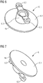
- Fig. 6 and Fig. 7 illustrate the suppression element 6 in a higher level of detail.
- the suppression element 6 comprises at least three segments, namely a suppression portion 6.1, a retaining portion 6.2 and at least one fastening portion 6.3.
- the suppression portion 6.1 which is to be arranged in close proximity to the muffle wall 2.1 in the area of the opening 3 comprises a disk-like shape.
- the suppression portion 6.1 is followed by the retaining portion 6.2 which provides a spacing of the suppression portion 6.1 from the motor mounting element 7.
- the suppression portion 6.1 and the retaining portion 6.2 comprise openings which are arranged in alignment to each other.
- the retaining portion 6.2 comprises a bushing-like shape.
- the fastening portion 6.3 is constituted by a pair of straps protruding radially from the retaining portion 6.2 at opposite sides. Each strap comprises at least one opening for screwing the fastening portion 6.3 and thereby the whole suppression element 6 at the motor mounting element 7.
- the suppression element 6 is constituted by a one-piece element made of an electrically conductive material.
Landscapes
- Physics & Mathematics (AREA)
- Electromagnetism (AREA)
- Constitution Of High-Frequency Heating (AREA)
- Electric Ovens (AREA)
Priority Applications (6)
| Application Number | Priority Date | Filing Date | Title |
|---|---|---|---|
| EP13191105.9A EP2869667B1 (en) | 2013-10-31 | 2013-10-31 | Microwave oven |
| AU2014344182A AU2014344182B2 (en) | 2013-10-31 | 2014-07-24 | Microwave oven |
| PCT/EP2014/065953 WO2015062754A1 (en) | 2013-10-31 | 2014-07-24 | Microwave oven |
| BR112016009160-4A BR112016009160B1 (pt) | 2013-10-31 | 2014-07-24 | Forno micro-ondas |
| US14/915,077 US10149353B2 (en) | 2013-10-31 | 2014-07-24 | Microwave oven |
| CN201480051974.0A CN105580495B (zh) | 2013-10-31 | 2014-07-24 | 微波炉 |
Applications Claiming Priority (1)
| Application Number | Priority Date | Filing Date | Title |
|---|---|---|---|
| EP13191105.9A EP2869667B1 (en) | 2013-10-31 | 2013-10-31 | Microwave oven |
Publications (2)
| Publication Number | Publication Date |
|---|---|
| EP2869667A1 EP2869667A1 (en) | 2015-05-06 |
| EP2869667B1 true EP2869667B1 (en) | 2021-12-15 |
Family
ID=49515249
Family Applications (1)
| Application Number | Title | Priority Date | Filing Date |
|---|---|---|---|
| EP13191105.9A Active EP2869667B1 (en) | 2013-10-31 | 2013-10-31 | Microwave oven |
Country Status (6)
| Country | Link |
|---|---|
| US (1) | US10149353B2 (https=) |
| EP (1) | EP2869667B1 (https=) |
| CN (1) | CN105580495B (https=) |
| AU (1) | AU2014344182B2 (https=) |
| BR (1) | BR112016009160B1 (https=) |
| WO (1) | WO2015062754A1 (https=) |
Families Citing this family (2)
| Publication number | Priority date | Publication date | Assignee | Title |
|---|---|---|---|---|
| EP3343110B1 (en) * | 2015-08-26 | 2019-10-23 | Panasonic Intellectual Property Management Co., Ltd. | Cooker |
| CN107543215B (zh) * | 2017-08-31 | 2019-07-02 | 广东美的厨房电器制造有限公司 | 烹饪电器 |
Family Cites Families (7)
| Publication number | Priority date | Publication date | Assignee | Title |
|---|---|---|---|---|
| US4053730A (en) * | 1976-05-17 | 1977-10-11 | Litton Systems Inc. | Microwave oven shaft seal |
| US4327266A (en) * | 1980-09-12 | 1982-04-27 | Amana Refrigeration, Inc. | Microwave ovens for uniform heating |
| FR2637053B1 (fr) * | 1988-09-29 | 1990-11-16 | Scholtes Ets Eugen | Four de cuisson mixte |
| US4845327A (en) * | 1988-11-15 | 1989-07-04 | Hitachi Heating Appliances Co., Ltd. | Microwave oven having automatic bread making function |
| DE4105300C2 (de) | 1991-02-20 | 1997-02-13 | Bosch Siemens Hausgeraete | Gebläse für einen Umluftherd |
| EP2247160B1 (en) * | 2009-05-02 | 2012-11-28 | Electrolux Home Products Corporation N.V. | A microwave sealing device of an opening for a rotating shaft |
| ES2590035T3 (es) * | 2009-12-30 | 2016-11-17 | Arçelik Anonim Sirketi | Un horno |
-
2013
- 2013-10-31 EP EP13191105.9A patent/EP2869667B1/en active Active
-
2014
- 2014-07-24 CN CN201480051974.0A patent/CN105580495B/zh not_active Expired - Fee Related
- 2014-07-24 BR BR112016009160-4A patent/BR112016009160B1/pt not_active IP Right Cessation
- 2014-07-24 US US14/915,077 patent/US10149353B2/en active Active
- 2014-07-24 WO PCT/EP2014/065953 patent/WO2015062754A1/en not_active Ceased
- 2014-07-24 AU AU2014344182A patent/AU2014344182B2/en not_active Ceased
Also Published As
| Publication number | Publication date |
|---|---|
| CN105580495A (zh) | 2016-05-11 |
| US20160212802A1 (en) | 2016-07-21 |
| US10149353B2 (en) | 2018-12-04 |
| EP2869667A1 (en) | 2015-05-06 |
| BR112016009160A2 (https=) | 2017-08-01 |
| BR112016009160B1 (pt) | 2022-02-08 |
| AU2014344182B2 (en) | 2018-10-04 |
| CN105580495B (zh) | 2019-07-12 |
| AU2014344182A1 (en) | 2016-03-10 |
| WO2015062754A1 (en) | 2015-05-07 |
Similar Documents
| Publication | Publication Date | Title |
|---|---|---|
| US20120001505A1 (en) | Electric machine | |
| EP2869667B1 (en) | Microwave oven | |
| US20150145382A1 (en) | Electronic housing for an electric motor with protection against accidental contact | |
| US7015443B2 (en) | Sheathed electric heating element support bracket for RF cooking applications | |
| US12140320B2 (en) | Oven cavity wrapper having a structural embossment and associated convection features | |
| CN212489547U (zh) | 内胆组件、烹饪装置及蒸烤机 | |
| US11503678B2 (en) | Cooking appliance device and method for operating a cooking appliance device | |
| KR101620100B1 (ko) | 빌트인 타입 조리기기 | |
| EP1559959B1 (en) | Baking oven with a heater / fan assembly | |
| EP4082297A1 (en) | Induction cooking device | |
| CN220800808U (zh) | 烹饪器具 | |
| KR200231120Y1 (ko) | 전자레인지의 스터러팬 설치구조 | |
| KR20100081242A (ko) | 다기능 전자레인지의 히터결합체 | |
| CN100441957C (zh) | 烧烤型微波炉烧烤管架 | |
| US20220386495A1 (en) | Electric range | |
| CN220859882U (zh) | 蒸烤箱箱体结构 | |
| CN115211715B (zh) | 蒸烤装置 | |
| CN111543846B (zh) | 内胆组件、烹饪装置及蒸烤机 | |
| US20230013590A1 (en) | Twist lock convection motor mount | |
| EP2711635B1 (en) | Cooking oven with heating element | |
| KR200183818Y1 (ko) | 전자렌지용 컨벡션 팬 | |
| KR20250107651A (ko) | 조리기기 | |
| KR100601426B1 (ko) | 단열 기능을 가진 전자렌지의 컨벡션 단열팬 | |
| CN108012360B (zh) | 线圈盘和电磁烹饪器具 | |
| KR200307045Y1 (ko) | 전자레인지용 블로워유니트 커버어셈블리 |
Legal Events
| Date | Code | Title | Description |
|---|---|---|---|
| PUAI | Public reference made under article 153(3) epc to a published international application that has entered the european phase |
Free format text: ORIGINAL CODE: 0009012 |
|
| 17P | Request for examination filed |
Effective date: 20131031 |
|
| AK | Designated contracting states |
Kind code of ref document: A1 Designated state(s): AL AT BE BG CH CY CZ DE DK EE ES FI FR GB GR HR HU IE IS IT LI LT LU LV MC MK MT NL NO PL PT RO RS SE SI SK SM TR |
|
| AX | Request for extension of the european patent |
Extension state: BA ME |
|
| R17P | Request for examination filed (corrected) |
Effective date: 20151027 |
|
| RBV | Designated contracting states (corrected) |
Designated state(s): AL AT BE BG CH CY CZ DE DK EE ES FI FR GB GR HR HU IE IS IT LI LT LU LV MC MK MT NL NO PL PT RO RS SE SI SK SM TR |
|
| STAA | Information on the status of an ep patent application or granted ep patent |
Free format text: STATUS: EXAMINATION IS IN PROGRESS |
|
| 17Q | First examination report despatched |
Effective date: 20171110 |
|
| GRAP | Despatch of communication of intention to grant a patent |
Free format text: ORIGINAL CODE: EPIDOSNIGR1 |
|
| STAA | Information on the status of an ep patent application or granted ep patent |
Free format text: STATUS: GRANT OF PATENT IS INTENDED |
|
| INTG | Intention to grant announced |
Effective date: 20210721 |
|
| GRAS | Grant fee paid |
Free format text: ORIGINAL CODE: EPIDOSNIGR3 |
|
| GRAA | (expected) grant |
Free format text: ORIGINAL CODE: 0009210 |
|
| STAA | Information on the status of an ep patent application or granted ep patent |
Free format text: STATUS: THE PATENT HAS BEEN GRANTED |
|
| AK | Designated contracting states |
Kind code of ref document: B1 Designated state(s): AL AT BE BG CH CY CZ DE DK EE ES FI FR GB GR HR HU IE IS IT LI LT LU LV MC MK MT NL NO PL PT RO RS SE SI SK SM TR |
|
| REG | Reference to a national code |
Ref country code: GB Ref legal event code: FG4D Ref country code: CH Ref legal event code: EP |
|
| REG | Reference to a national code |
Ref country code: IE Ref legal event code: FG4D Ref country code: DE Ref legal event code: R096 Ref document number: 602013080403 Country of ref document: DE |
|
| REG | Reference to a national code |
Ref country code: AT Ref legal event code: REF Ref document number: 1456455 Country of ref document: AT Kind code of ref document: T Effective date: 20220115 |
|
| REG | Reference to a national code |
Ref country code: LT Ref legal event code: MG9D |
|
| REG | Reference to a national code |
Ref country code: NL Ref legal event code: MP Effective date: 20211215 |
|
| PG25 | Lapsed in a contracting state [announced via postgrant information from national office to epo] |
Ref country code: RS Free format text: LAPSE BECAUSE OF FAILURE TO SUBMIT A TRANSLATION OF THE DESCRIPTION OR TO PAY THE FEE WITHIN THE PRESCRIBED TIME-LIMIT Effective date: 20211215 Ref country code: LT Free format text: LAPSE BECAUSE OF FAILURE TO SUBMIT A TRANSLATION OF THE DESCRIPTION OR TO PAY THE FEE WITHIN THE PRESCRIBED TIME-LIMIT Effective date: 20211215 Ref country code: FI Free format text: LAPSE BECAUSE OF FAILURE TO SUBMIT A TRANSLATION OF THE DESCRIPTION OR TO PAY THE FEE WITHIN THE PRESCRIBED TIME-LIMIT Effective date: 20211215 Ref country code: BG Free format text: LAPSE BECAUSE OF FAILURE TO SUBMIT A TRANSLATION OF THE DESCRIPTION OR TO PAY THE FEE WITHIN THE PRESCRIBED TIME-LIMIT Effective date: 20220315 |
|
| REG | Reference to a national code |
Ref country code: AT Ref legal event code: MK05 Ref document number: 1456455 Country of ref document: AT Kind code of ref document: T Effective date: 20211215 |
|
| PG25 | Lapsed in a contracting state [announced via postgrant information from national office to epo] |
Ref country code: SE Free format text: LAPSE BECAUSE OF FAILURE TO SUBMIT A TRANSLATION OF THE DESCRIPTION OR TO PAY THE FEE WITHIN THE PRESCRIBED TIME-LIMIT Effective date: 20211215 Ref country code: NO Free format text: LAPSE BECAUSE OF FAILURE TO SUBMIT A TRANSLATION OF THE DESCRIPTION OR TO PAY THE FEE WITHIN THE PRESCRIBED TIME-LIMIT Effective date: 20220315 Ref country code: LV Free format text: LAPSE BECAUSE OF FAILURE TO SUBMIT A TRANSLATION OF THE DESCRIPTION OR TO PAY THE FEE WITHIN THE PRESCRIBED TIME-LIMIT Effective date: 20211215 Ref country code: HR Free format text: LAPSE BECAUSE OF FAILURE TO SUBMIT A TRANSLATION OF THE DESCRIPTION OR TO PAY THE FEE WITHIN THE PRESCRIBED TIME-LIMIT Effective date: 20211215 Ref country code: GR Free format text: LAPSE BECAUSE OF FAILURE TO SUBMIT A TRANSLATION OF THE DESCRIPTION OR TO PAY THE FEE WITHIN THE PRESCRIBED TIME-LIMIT Effective date: 20220316 |
|
| PG25 | Lapsed in a contracting state [announced via postgrant information from national office to epo] |
Ref country code: NL Free format text: LAPSE BECAUSE OF FAILURE TO SUBMIT A TRANSLATION OF THE DESCRIPTION OR TO PAY THE FEE WITHIN THE PRESCRIBED TIME-LIMIT Effective date: 20211215 |
|
| PG25 | Lapsed in a contracting state [announced via postgrant information from national office to epo] |
Ref country code: SM Free format text: LAPSE BECAUSE OF FAILURE TO SUBMIT A TRANSLATION OF THE DESCRIPTION OR TO PAY THE FEE WITHIN THE PRESCRIBED TIME-LIMIT Effective date: 20211215 Ref country code: SK Free format text: LAPSE BECAUSE OF FAILURE TO SUBMIT A TRANSLATION OF THE DESCRIPTION OR TO PAY THE FEE WITHIN THE PRESCRIBED TIME-LIMIT Effective date: 20211215 Ref country code: RO Free format text: LAPSE BECAUSE OF FAILURE TO SUBMIT A TRANSLATION OF THE DESCRIPTION OR TO PAY THE FEE WITHIN THE PRESCRIBED TIME-LIMIT Effective date: 20211215 Ref country code: PT Free format text: LAPSE BECAUSE OF FAILURE TO SUBMIT A TRANSLATION OF THE DESCRIPTION OR TO PAY THE FEE WITHIN THE PRESCRIBED TIME-LIMIT Effective date: 20220418 Ref country code: ES Free format text: LAPSE BECAUSE OF FAILURE TO SUBMIT A TRANSLATION OF THE DESCRIPTION OR TO PAY THE FEE WITHIN THE PRESCRIBED TIME-LIMIT Effective date: 20211215 Ref country code: EE Free format text: LAPSE BECAUSE OF FAILURE TO SUBMIT A TRANSLATION OF THE DESCRIPTION OR TO PAY THE FEE WITHIN THE PRESCRIBED TIME-LIMIT Effective date: 20211215 Ref country code: CZ Free format text: LAPSE BECAUSE OF FAILURE TO SUBMIT A TRANSLATION OF THE DESCRIPTION OR TO PAY THE FEE WITHIN THE PRESCRIBED TIME-LIMIT Effective date: 20211215 |
|
| PG25 | Lapsed in a contracting state [announced via postgrant information from national office to epo] |
Ref country code: PL Free format text: LAPSE BECAUSE OF FAILURE TO SUBMIT A TRANSLATION OF THE DESCRIPTION OR TO PAY THE FEE WITHIN THE PRESCRIBED TIME-LIMIT Effective date: 20211215 Ref country code: AT Free format text: LAPSE BECAUSE OF FAILURE TO SUBMIT A TRANSLATION OF THE DESCRIPTION OR TO PAY THE FEE WITHIN THE PRESCRIBED TIME-LIMIT Effective date: 20211215 |
|
| REG | Reference to a national code |
Ref country code: DE Ref legal event code: R097 Ref document number: 602013080403 Country of ref document: DE |
|
| PG25 | Lapsed in a contracting state [announced via postgrant information from national office to epo] |
Ref country code: IS Free format text: LAPSE BECAUSE OF FAILURE TO SUBMIT A TRANSLATION OF THE DESCRIPTION OR TO PAY THE FEE WITHIN THE PRESCRIBED TIME-LIMIT Effective date: 20220415 |
|
| PLBE | No opposition filed within time limit |
Free format text: ORIGINAL CODE: 0009261 |
|
| STAA | Information on the status of an ep patent application or granted ep patent |
Free format text: STATUS: NO OPPOSITION FILED WITHIN TIME LIMIT |
|
| PG25 | Lapsed in a contracting state [announced via postgrant information from national office to epo] |
Ref country code: DK Free format text: LAPSE BECAUSE OF FAILURE TO SUBMIT A TRANSLATION OF THE DESCRIPTION OR TO PAY THE FEE WITHIN THE PRESCRIBED TIME-LIMIT Effective date: 20211215 Ref country code: AL Free format text: LAPSE BECAUSE OF FAILURE TO SUBMIT A TRANSLATION OF THE DESCRIPTION OR TO PAY THE FEE WITHIN THE PRESCRIBED TIME-LIMIT Effective date: 20211215 |
|
| 26N | No opposition filed |
Effective date: 20220916 |
|
| PG25 | Lapsed in a contracting state [announced via postgrant information from national office to epo] |
Ref country code: SI Free format text: LAPSE BECAUSE OF FAILURE TO SUBMIT A TRANSLATION OF THE DESCRIPTION OR TO PAY THE FEE WITHIN THE PRESCRIBED TIME-LIMIT Effective date: 20211215 |
|
| PG25 | Lapsed in a contracting state [announced via postgrant information from national office to epo] |
Ref country code: MC Free format text: LAPSE BECAUSE OF FAILURE TO SUBMIT A TRANSLATION OF THE DESCRIPTION OR TO PAY THE FEE WITHIN THE PRESCRIBED TIME-LIMIT Effective date: 20211215 |
|
| REG | Reference to a national code |
Ref country code: CH Ref legal event code: PL |
|
| REG | Reference to a national code |
Ref country code: BE Ref legal event code: MM Effective date: 20221031 |
|
| GBPC | Gb: european patent ceased through non-payment of renewal fee |
Effective date: 20221031 |
|
| PG25 | Lapsed in a contracting state [announced via postgrant information from national office to epo] |
Ref country code: LU Free format text: LAPSE BECAUSE OF NON-PAYMENT OF DUE FEES Effective date: 20221031 |
|
| PG25 | Lapsed in a contracting state [announced via postgrant information from national office to epo] |
Ref country code: LI Free format text: LAPSE BECAUSE OF NON-PAYMENT OF DUE FEES Effective date: 20221031 Ref country code: FR Free format text: LAPSE BECAUSE OF NON-PAYMENT OF DUE FEES Effective date: 20221031 Ref country code: CH Free format text: LAPSE BECAUSE OF NON-PAYMENT OF DUE FEES Effective date: 20221031 |
|
| P01 | Opt-out of the competence of the unified patent court (upc) registered |
Effective date: 20230625 |
|
| PG25 | Lapsed in a contracting state [announced via postgrant information from national office to epo] |
Ref country code: BE Free format text: LAPSE BECAUSE OF NON-PAYMENT OF DUE FEES Effective date: 20221031 |
|
| PG25 | Lapsed in a contracting state [announced via postgrant information from national office to epo] |
Ref country code: IE Free format text: LAPSE BECAUSE OF NON-PAYMENT OF DUE FEES Effective date: 20221031 Ref country code: GB Free format text: LAPSE BECAUSE OF NON-PAYMENT OF DUE FEES Effective date: 20221031 |
|
| PG25 | Lapsed in a contracting state [announced via postgrant information from national office to epo] |
Ref country code: HU Free format text: LAPSE BECAUSE OF FAILURE TO SUBMIT A TRANSLATION OF THE DESCRIPTION OR TO PAY THE FEE WITHIN THE PRESCRIBED TIME-LIMIT; INVALID AB INITIO Effective date: 20131031 |
|
| PG25 | Lapsed in a contracting state [announced via postgrant information from national office to epo] |
Ref country code: CY Free format text: LAPSE BECAUSE OF FAILURE TO SUBMIT A TRANSLATION OF THE DESCRIPTION OR TO PAY THE FEE WITHIN THE PRESCRIBED TIME-LIMIT Effective date: 20211215 |
|
| PG25 | Lapsed in a contracting state [announced via postgrant information from national office to epo] |
Ref country code: MK Free format text: LAPSE BECAUSE OF FAILURE TO SUBMIT A TRANSLATION OF THE DESCRIPTION OR TO PAY THE FEE WITHIN THE PRESCRIBED TIME-LIMIT Effective date: 20211215 |
|
| PG25 | Lapsed in a contracting state [announced via postgrant information from national office to epo] |
Ref country code: TR Free format text: LAPSE BECAUSE OF FAILURE TO SUBMIT A TRANSLATION OF THE DESCRIPTION OR TO PAY THE FEE WITHIN THE PRESCRIBED TIME-LIMIT Effective date: 20211215 |
|
| PG25 | Lapsed in a contracting state [announced via postgrant information from national office to epo] |
Ref country code: MT Free format text: LAPSE BECAUSE OF FAILURE TO SUBMIT A TRANSLATION OF THE DESCRIPTION OR TO PAY THE FEE WITHIN THE PRESCRIBED TIME-LIMIT Effective date: 20211215 |
|
| PGFP | Annual fee paid to national office [announced via postgrant information from national office to epo] |
Ref country code: DE Payment date: 20251028 Year of fee payment: 13 |
|
| PGFP | Annual fee paid to national office [announced via postgrant information from national office to epo] |
Ref country code: IT Payment date: 20251022 Year of fee payment: 13 |