EP2869412A2 - Optical module and atomic oscillator - Google Patents
Optical module and atomic oscillator Download PDFInfo
- Publication number
- EP2869412A2 EP2869412A2 EP20140190655 EP14190655A EP2869412A2 EP 2869412 A2 EP2869412 A2 EP 2869412A2 EP 20140190655 EP20140190655 EP 20140190655 EP 14190655 A EP14190655 A EP 14190655A EP 2869412 A2 EP2869412 A2 EP 2869412A2
- Authority
- EP
- European Patent Office
- Prior art keywords
- polarized light
- polarization
- light
- emitting laser
- surface emitting
- Prior art date
- Legal status (The legal status is an assumption and is not a legal conclusion. Google has not performed a legal analysis and makes no representation as to the accuracy of the status listed.)
- Withdrawn
Links
- 230000003287 optical effect Effects 0.000 title claims abstract description 50
- 230000010287 polarization Effects 0.000 claims abstract description 197
- 230000005540 biological transmission Effects 0.000 claims abstract description 35
- 150000001340 alkali metals Chemical class 0.000 claims abstract description 25
- 229910052783 alkali metal Inorganic materials 0.000 claims abstract description 20
- 238000001514 detection method Methods 0.000 abstract description 22
- 238000010521 absorption reaction Methods 0.000 abstract description 2
- 238000010586 diagram Methods 0.000 description 14
- 230000001902 propagating effect Effects 0.000 description 8
- 230000005684 electric field Effects 0.000 description 7
- 239000000758 substrate Substances 0.000 description 7
- 230000008901 benefit Effects 0.000 description 5
- 238000005259 measurement Methods 0.000 description 5
- 230000001427 coherent effect Effects 0.000 description 4
- 238000011156 evaluation Methods 0.000 description 4
- 239000004065 semiconductor Substances 0.000 description 4
- 229910001218 Gallium arsenide Inorganic materials 0.000 description 3
- 230000032683 aging Effects 0.000 description 2
- 230000008859 change Effects 0.000 description 2
- 230000003247 decreasing effect Effects 0.000 description 2
- 230000000694 effects Effects 0.000 description 2
- 238000001228 spectrum Methods 0.000 description 2
- 230000035882 stress Effects 0.000 description 2
- 238000002834 transmittance Methods 0.000 description 2
- 230000005699 Stark effect Effects 0.000 description 1
- 229910052792 caesium Chemical group 0.000 description 1
- TVFDJXOCXUVLDH-UHFFFAOYSA-N caesium atom Chemical group [Cs] TVFDJXOCXUVLDH-UHFFFAOYSA-N 0.000 description 1
- 239000000470 constituent Substances 0.000 description 1
- 239000013078 crystal Substances 0.000 description 1
- 238000005516 engineering process Methods 0.000 description 1
- 230000003993 interaction Effects 0.000 description 1
- 230000001678 irradiating effect Effects 0.000 description 1
- 230000031700 light absorption Effects 0.000 description 1
- 239000010445 mica Substances 0.000 description 1
- 229910052618 mica group Inorganic materials 0.000 description 1
- 239000010453 quartz Substances 0.000 description 1
- 230000009467 reduction Effects 0.000 description 1
- 230000004044 response Effects 0.000 description 1
- IGLNJRXAVVLDKE-UHFFFAOYSA-N rubidium atom Chemical group [Rb] IGLNJRXAVVLDKE-UHFFFAOYSA-N 0.000 description 1
- VYPSYNLAJGMNEJ-UHFFFAOYSA-N silicon dioxide Inorganic materials O=[Si]=O VYPSYNLAJGMNEJ-UHFFFAOYSA-N 0.000 description 1
- 125000004436 sodium atom Chemical group 0.000 description 1
- 239000007787 solid Substances 0.000 description 1
Images




Classifications
-
- G—PHYSICS
- G02—OPTICS
- G02B—OPTICAL ELEMENTS, SYSTEMS OR APPARATUS
- G02B27/00—Optical systems or apparatus not provided for by any of the groups G02B1/00 - G02B26/00, G02B30/00
- G02B27/28—Optical systems or apparatus not provided for by any of the groups G02B1/00 - G02B26/00, G02B30/00 for polarising
- G02B27/286—Optical systems or apparatus not provided for by any of the groups G02B1/00 - G02B26/00, G02B30/00 for polarising for controlling or changing the state of polarisation, e.g. transforming one polarisation state into another
-
- G—PHYSICS
- G04—HOROLOGY
- G04F—TIME-INTERVAL MEASURING
- G04F5/00—Apparatus for producing preselected time intervals for use as timing standards
- G04F5/14—Apparatus for producing preselected time intervals for use as timing standards using atomic clocks
- G04F5/145—Apparatus for producing preselected time intervals for use as timing standards using atomic clocks using Coherent Population Trapping
-
- H—ELECTRICITY
- H01—ELECTRIC ELEMENTS
- H01S—DEVICES USING THE PROCESS OF LIGHT AMPLIFICATION BY STIMULATED EMISSION OF RADIATION [LASER] TO AMPLIFY OR GENERATE LIGHT; DEVICES USING STIMULATED EMISSION OF ELECTROMAGNETIC RADIATION IN WAVE RANGES OTHER THAN OPTICAL
- H01S5/00—Semiconductor lasers
- H01S5/06—Arrangements for controlling the laser output parameters, e.g. by operating on the active medium
- H01S5/062—Arrangements for controlling the laser output parameters, e.g. by operating on the active medium by varying the potential of the electrodes
- H01S5/06226—Modulation at ultra-high frequencies
- H01S5/0623—Modulation at ultra-high frequencies using the beating between two closely spaced optical frequencies, i.e. heterodyne mixing
-
- H—ELECTRICITY
- H01—ELECTRIC ELEMENTS
- H01S—DEVICES USING THE PROCESS OF LIGHT AMPLIFICATION BY STIMULATED EMISSION OF RADIATION [LASER] TO AMPLIFY OR GENERATE LIGHT; DEVICES USING STIMULATED EMISSION OF ELECTROMAGNETIC RADIATION IN WAVE RANGES OTHER THAN OPTICAL
- H01S5/00—Semiconductor lasers
- H01S5/06—Arrangements for controlling the laser output parameters, e.g. by operating on the active medium
- H01S5/068—Stabilisation of laser output parameters
- H01S5/0683—Stabilisation of laser output parameters by monitoring the optical output parameters
- H01S5/0687—Stabilising the frequency of the laser
-
- H—ELECTRICITY
- H03—ELECTRONIC CIRCUITRY
- H03L—AUTOMATIC CONTROL, STARTING, SYNCHRONISATION OR STABILISATION OF GENERATORS OF ELECTRONIC OSCILLATIONS OR PULSES
- H03L7/00—Automatic control of frequency or phase; Synchronisation
- H03L7/26—Automatic control of frequency or phase; Synchronisation using energy levels of molecules, atoms, or subatomic particles as a frequency reference
-
- H—ELECTRICITY
- H01—ELECTRIC ELEMENTS
- H01S—DEVICES USING THE PROCESS OF LIGHT AMPLIFICATION BY STIMULATED EMISSION OF RADIATION [LASER] TO AMPLIFY OR GENERATE LIGHT; DEVICES USING STIMULATED EMISSION OF ELECTROMAGNETIC RADIATION IN WAVE RANGES OTHER THAN OPTICAL
- H01S5/00—Semiconductor lasers
- H01S5/005—Optical components external to the laser cavity, specially adapted therefor, e.g. for homogenisation or merging of the beams or for manipulating laser pulses, e.g. pulse shaping
-
- H—ELECTRICITY
- H01—ELECTRIC ELEMENTS
- H01S—DEVICES USING THE PROCESS OF LIGHT AMPLIFICATION BY STIMULATED EMISSION OF RADIATION [LASER] TO AMPLIFY OR GENERATE LIGHT; DEVICES USING STIMULATED EMISSION OF ELECTROMAGNETIC RADIATION IN WAVE RANGES OTHER THAN OPTICAL
- H01S5/00—Semiconductor lasers
- H01S5/06—Arrangements for controlling the laser output parameters, e.g. by operating on the active medium
- H01S5/068—Stabilisation of laser output parameters
- H01S5/0683—Stabilisation of laser output parameters by monitoring the optical output parameters
- H01S5/06832—Stabilising during amplitude modulation
-
- H—ELECTRICITY
- H01—ELECTRIC ELEMENTS
- H01S—DEVICES USING THE PROCESS OF LIGHT AMPLIFICATION BY STIMULATED EMISSION OF RADIATION [LASER] TO AMPLIFY OR GENERATE LIGHT; DEVICES USING STIMULATED EMISSION OF ELECTROMAGNETIC RADIATION IN WAVE RANGES OTHER THAN OPTICAL
- H01S5/00—Semiconductor lasers
- H01S5/10—Construction or shape of the optical resonator, e.g. extended or external cavity, coupled cavities, bent-guide, varying width, thickness or composition of the active region
- H01S5/18—Surface-emitting [SE] lasers, e.g. having both horizontal and vertical cavities
- H01S5/183—Surface-emitting [SE] lasers, e.g. having both horizontal and vertical cavities having only vertical cavities, e.g. vertical cavity surface-emitting lasers [VCSEL]
- H01S5/18355—Surface-emitting [SE] lasers, e.g. having both horizontal and vertical cavities having only vertical cavities, e.g. vertical cavity surface-emitting lasers [VCSEL] having a defined polarisation
Definitions
- the present invention relates to an optical module and an atomic oscillator.
- the atomic oscillator using CPT uses an electromagnetically induced transparency phenomenon (EIT phenomenon) wherein the absorption of coherent light beams respectively having two different wavelengths (frequencies) stops if an alkali metal atom is irradiated with the coherent light beams.
- EIT phenomenon electromagnetically induced transparency phenomenon
- JP-A-2013-98606 there is disclosed an atomic oscillator in which the resonant light emitted from a light source is converted by a ⁇ /4 plate into circularly polarized light, and the gas cell encapsulating the alkali metal atoms is irradiated with the circularly polarized light in order to increase the probability of the EIT phenomenon occurring.
- the gas cell encapsulating the alkali metal atoms is irradiated with the circularly polarized light in order to increase the probability of the EIT phenomenon occurring.
- the light generated in a surface emitting laser has a coherent property, and is therefore suitable for obtaining a quantum interference effect.
- the surface emitting laser emits polarized light.
- the polarization direction of the polarized light to be emitted is changed, namely polarization switching occurs, due to an external factor (e.g., temperature, stress, and aging of the device structure).
- an external factor e.g., temperature, stress, and aging of the device structure.
- two polarization directions that are perpendicular to each other are normally allowed. Therefore, in such a VCSEL, since the polarization direction changes from one of the two directions to the other due to the polarization switching, namely the polarization direction rotates 90 degrees, it is not possible to determine the polarization direction of the polarized light to be emitted to one direction.
- the vertical cavity surface emitting laser (VCSEL) is applied as a light source of the atomic oscillator of JP-A-2013-98606 , the polarization direction of the polarized light to be emitted from the vertical cavity surface emitting laser is changed due to the polarization switching, and there is a problem that the polarization direction of the polarized light entering the ⁇ /4 plate is changed.
- An advantage of some aspects of the invention is to provide an optical module capable of making the polarization direction of the polarized light entering the ⁇ /4 plate constant even if the polarization direction of the polarized light emitted from the surface emitting laser is changed.
- Another advantage of some aspects of the invention is to provide an atomic oscillator including the optical module described above.
- An optical module is an optical module of an atomic oscillator, including a surface emitting laser (a light source) adapted to emit polarized light, a polarization element (a polarizer) irradiated with the light emitted from the surface emitting laser, and having a polarization transmission axis disposed so as to be rotated by 45 degrees with respect to a polarization direction of the polarized light, a ⁇ /4 plate irradiated with light having been transmitted through the polarization element, and having a fast axis disposed so as to be rotated by 45 degrees with respect to the polarization transmission axis, a gas cell encapsulating an alkali metal gas, and irradiated with light having been transmitted through the ⁇ /4 plate, and a light detection section (a light detector) adapted to detect an intensity of light having been transmitted through the gas cell.
- a surface emitting laser a light source
- a polarization element a polarizer
- a polarization transmission axis
- the polarization direction of the polarized light entering the ⁇ /4 plate can be set to a constant direction by the polarization element. Further, since the polarization transmission axis of the polarization element is disposed so as to be rotated by 45 degrees with respect to the polarization direction of the polarized light emitted by the surface emitting laser, the light intensity of the polarized light entering the ⁇ /4 plate can be made constant even in the case in which the polarization direction of the polarized light emitted by the surface emitting laser rotates by 90 degrees.
- the rotational direction and the light intensity of the circularly-polarized light with which the gas cell is irradiated can be made constant even in the case in which the polarization direction of the polarized light emitted by the surface emitting laser rotates by 90 degrees.
- the frequency stability of the atomic oscillator can be improved.
- the polarization direction of the polarized light emitted from the surface emitting laser may change from a first direction to a second direction perpendicular to the first direction.
- the rotational direction and the light intensity of the circularly-polarized light with which the gas cell is irradiated can be made constant even in the case in which the polarization direction of the polarized light emitted by the surface emitting laser changes from the first direction to the second direction (rotates by 90 degrees).
- An atomic oscillator according to another aspect of the invention includes the optical module according to the aspect of the invention.
- the rotational direction and the light intensity of the circularly-polarized light with which the gas cell is irradiated can be made constant even in the case in which the polarization direction of the polarized light emitted by the surface emitting laser rotates by 90 degrees.
- the frequency stability for example, can be improved.
- FIG. 1 is a block diagram showing the atomic oscillator 1 including the optical module 100 according to the present embodiment.
- the atomic oscillator 1 is configured including the optical module 100, a center wavelength control section 2, and a high-frequency control section 4.
- the optical module 100 is includes, in order, a surface emitting laser 10, a polarization element 20, a ⁇ /4 plate 30, a gas cell 40, and a light detection section 50.
- Figs. 2 and 3 are diagrams schematically showing the configuration of the optical module 100.
- Fig. 2 shows the case in which the polarization direction of the polarized light emitted from the surface emitting laser 10 is the Y direction
- Fig. 3 shows the case in which the polarization direction of the polarized light emitted from the surface emitting laser 10 is the X direction. Note that the X and Y directions are orthogonal to one another.
- the graphical description of the light detection section 50 is omitted for the sake of convenience.
- the Z axis is shown in Figs. 2 and 3 as an axis coinciding with the optical axis of the surface emitting laser 10.
- the optical axis of the surface emitting laser 10 denotes an axis passing through the center of the light beam emitted from the surface emitting laser 10 (e.g. , light cone).
- the X axis and the Y axis are shown in Figs. 2 and 3 , as axes perpendicular to each other, and perpendicular to the Z axis.
- the surface emitting laser 10 is, for example, a vertical cavity surface emitting laser (VCSEL) having a resonator configured perpendicularly to a semiconductor substrate.
- the surface emitting laser 10 is, for example, a single-mode VCSEL.
- the surface emitting laser 10 emits polarized light.
- the polarized light includes linearly-polarized light and elliptically-polarized light which can be assumed to be substantially linearly-polarized light.
- the linearly-polarized light denotes light having a vibration direction of the electric field of the light in a single plane.
- the elliptically-polarized light which can be assumed to be substantially linearly-polarized light denotes elliptically-polarized light having a length of the long axis sufficiently long with respect to the length of the short axis.
- the elliptically-polarized light has the ratio between the length a of the long axis and the length b of the short axis fulfilling the relationship of b/a ⁇ 0.1.
- the long axis of the elliptically-polarized light denotes the long axis of an ellipse drawn by a tip of a vibration vector of the electric field of the light in the elliptically-polarized light having the tip of the vibration vector making an elliptic motion.
- the short axis of the elliptically-polarized light denotes the short axis of such an ellipse.
- the polarized light is represented by a solid outlined arrow
- the light (the circularly-polarized light) having the tip of the vibration vector of the electric field making a circular motion is represented by a dashed outlined arrow.
- the surface emitting laser 10 may emit polarized light having two directions perpendicular to each other. Therefore, the polarization direction of the polarized light emitted from the surface emitting laser 10 may be either one of the two directions.
- the polarization direction of the polarized light denotes the vibration direction of the electric field in the linearly-polarized light.
- the polarization direction of the polarized light denotes the direction of the long axis of the elliptically-polarized light in the elliptically-polarized light which can be assumed to be substantially linearly-polarized light. In the example shown in Figs.
- the polarized light in the X direction (a first direction) and the polarized light in the Y direction (a second direction) are allowed in the surface emitting laser 10, and the polarization direction of the polarized light emitted from the surface emitting laser 10 is one of the X direction and the Y direction.
- the polarized light is allowed in a [011] -axis direction (e.g., the X direction) or in a [0-11] -axis direction (e.g., the Y direction). Therefore, the polarization direction of the polarized light emitted from such a surface emitting laser 10 is either one of the [011] -axis direction and the [0-11]-axis direction.
- the polarization switching in which the polarization direction of the polarized light to be emitted is changed, occurs due to an external factor (e.g., temperature, stress, and aging of a device structure).
- the polarization direction is changed from one (the first direction) of the two directions in which the polarization is allowed to the other (the second direction) thereof due to the polarization switching.
- the polarization switching occurs in the case in which the polarization direction of the polarized light to be emitted is the Y direction (see Fig. 2 )
- the polarization direction of the polarized light to be emitted changes to the X direction (see Fig. 3 ).
- the polarization direction of the polarized light to be emitted changes to the Y direction (see Fig. 2 ).
- the polarization direction of the polarized light to be emitted from the surface emitting laser 10 changes to the [0-11]-axis direction.
- the polarization direction of the polarized light to be emitted changes to the [011]-axis direction.
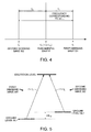
- Fig. 4 is a diagram showing a frequency spectrum of the light emitted by the surface emitting laser 10.
- Fig. 5 is a diagram showing a relationship between a ⁇ -type three-level model of the alkali metal atom, and a first sideband wave W1 and a second sideband wave W2.
- the frequency difference between the frequency f 1 of the first sideband wave W1 and the frequency f 2 of the second sideband wave W2 coincides with the frequency corresponding to the energy difference ⁇ E 12 between the ground level GL1 and the ground level GL2 of the alkali metal atom. Therefore, the alkali metal atom causes the EIT phenomenon with the first sideband wave W1 having the frequency f 1 and the second sideband wave W2 having the frequency f 2 .
- the polarization element 20 is, for example, a polarization plate for transmitting only the light polarized in the direction of a polarization transmission axis 20t out of the incident light.
- the polarization transmission axis 20t denotes an axis for transmitting the vibration of the electric field of the light.
- the polarization transmission axis 20t of the polarization element 20 is disposed so as to be rotated by 45 degrees with respect to the polarization direction of the polarized light emitted from the surface emitting laser 10.
- the polarization transmission axis 20t of the polarization element 20 is disposed so as to be tilted by 45 degrees around the optical axis with respect to the polarization direction of the polarized light emitted from the surface emitting laser 10.
- the polarization transmission axis 20t of the polarization element 20 is disposed so as to form an angle of 45 degrees with both of the two directions.
- the polarization direction of the polarized light to be emitted from the surface emitting laser 10 is one of the [011] -axis direction and the [0-11]-axis direction. Therefore, the polarization transmission axis 20t of the polarization element 20 is disposed so as to form an angle of 45 degrees with respect to both of the [011] -axis direction and the [0-11] -axis direction.
- the polarization direction of the polarized light emitted from the surface emitting laser 10 is one of the X direction and the Y direction. Therefore, the polarization transmission axis 20t of the polarization element 20 is disposed so as to rotate (be tilted) clockwise by 45 degrees with respect to the Y axis toward the propagating direction of the polarized light. In other words, the polarization transmission axis 20t of the polarization element 20 is disposed so as to rotate (be tilted) counterclockwise by 45 degrees with respect to the X axis toward the propagating direction of the polarized light.
- the polarization transmission axis 20t of the polarization element 20 can also be disposed so as to rotate (be tilted) counterclockwise by 45 degrees with respect to the Y axis toward the propagating direction of the polarized light.
- the polarization element 20 is irradiated with the light emitted from the surface emitting laser 10.
- the polarization direction of the polarized light emitted from the surface emitting laser 10 is the Y direction. Therefore, the light transmitted through the polarization element 20 becomes polarized light polarized in the direction tilted by 45 degrees clockwise with respect to the Y axis (counterclockwise with respect to the X axis) toward the propagating direction of the polarized light.
- the polarization direction of the polarized light emitted from the surface emitting laser 10 is the X direction.
- the light transmitted through the polarization element 20 becomes polarized light polarized in the direction tilted by 45 degrees clockwise with respect to the Y axis (counterclockwise with respect to the X axis) toward the propagating direction of the polarized light similarly to the example shown in Fig. 2 .
- the polarization direction of the polarized light emitted from the surface emitting laser 10 rotates by 90 degrees (i.e., the polarization direction is changed from the Y direction to the X direction)
- the light transmitted through the polarization element 20 becomes polarized light having the same polarization direction.
- the light intensity (transmitted light intensity) of the light transmitted through the polarization element 20 becomes the same between the case in which the polarization direction of the polarized light having entered the polarization element 20 is the Y direction (the case of Fig. 2 ) and the case in which the polarization direction of the polarized light having entered the polarization element 20 is the X direction (the case of Fig. 3 ).
- the angle formed between the polarization direction (the X direction or the Y direction) of the polarized light entering the polarization element 20 and the polarization transmission axis 20t of the polarization element 20 is the same angle (45 degrees) among the case of Fig. 2 and the case of Fig. 3 .
- the light intensity of the light having been transmitted through the polarization element 20 is decreased (e.g., roughly 1/2) compared to the light intensity of the light when entering the polarization element 20.
- the decrease in light intensity in the polarization element 20 does not affect the operation of the atomic oscillator 1.
- the ⁇ /4 plate 30 is a wave plate for providing an optical path difference (a phase difference of 90°) of a quarter wavelength between the linearly-polarized light components of light that is perpendicular to each other.
- the ⁇ /4 plate 30 converts the polarized light having a direction tilted by 45 degrees with respect to a fast axis 30f as the polarization direction into circularly-polarized light when the polarized light enters the ⁇ /4 plate 30.
- the fast axis 30f denotes an axis in a direction along which the ⁇ /4 plate has a low refractive index, and is an axis perpendicular to a slow axis (an axis along which the ⁇ /4 plate has a high refractive index) of the ⁇ /4 plate.
- a quartz crystal plate or a mica plate can be used as the ⁇ /4 plate 30.
- the ⁇ /4 plate 30 is irradiated with the light having been transmitted through the polarization element 20.
- the ⁇ /4 plate 30 is irradiated with the light (the polarized light having the direction of the polarization transmission axis 20t as the polarization direction) polarized in the direction of the polarization transmission axis 20t of the polarization element 20.
- the ⁇ /4 plate 30 is disposed so that the fast axis 30f is rotated by 45 degrees with respect to the polarization transmission axis 20t of the polarization element 20.
- the fast axis 30f of the ⁇ /4 plate 30 is disposed so as to be tilted by 45 degrees around the optical axis with respect to the polarization transmission axis 20t of the polarization element 20.
- the polarization direction of the polarized light entering the ⁇ /4 plate 30 has an angle tilted by 45 degrees with respect to the fast axis 30f of the ⁇ /4 plate 30. Therefore, the polarized light (the linearly-polarized light) having entered the ⁇ /4 plate 30 is converted into circularly-polarized light.
- the polarized light which is polarized in the direction tilted by 45 degrees clockwise with respect to the Y axis (counterclockwise with respect to the X axis) toward the propagating direction of the polarized light, enters the ⁇ /4 plate 30.
- the fast axis 30f of the ⁇ /4 plate 30 is disposed parallel to the X axis. Therefore, the angle of 45 degrees is formed between the fast axis 30f of the ⁇ /4 plate 30 and the polarization direction of the polarized light entering the ⁇ /4 plate 30, and the polarized light having entered is converted by the ⁇ /4 plate 30 into circularly-polarized light.
- the polarized light having entered the ⁇ /4 plate 30 is converted by the ⁇ /4 plate 30 into circularly-polarized light having the clockwise rotational direction, namely right circularly-polarized light.
- the rotational direction of the circularly-polarized light denotes the rotational direction (clockwise, counterclockwise) when viewing a circle drawn by the tip of the vibration vector of the electric field of the light from the propagating direction of the light in the circularly-polarized light having the tip of the vibration vector making a circular motion.
- the right circularly-polarized light denotes circularly-polarized light having the circle drawn by the tip of the vibration vector of the electric field of the light rotates clockwise viewed from the propagating direction of the light in the circularly-polarized light having the tip of the vibration vector making a circular motion.
- the ⁇ /4 plate 30 converts the polarized light having entered the ⁇ /4 plate 30 into the right circularly-polarized light
- the ⁇ /4 plate 30 it is also possible for the ⁇ /4 plate 30 to convert the polarized light having entered the ⁇ /4 plate 30 into left circularly-polarized light.
- the fast axis 30f of the ⁇ /4 plate 30 can also be disposed parallel to the Y axis.
- the gas cell 40 has the gaseous alkali metal atoms (e.g., sodium atoms, rubidium atoms, or cesium atoms) encapsulated in a container.
- the alkali metal atom causes the EIT phenomenon.
- the alkali metal atom is a cesium atom
- the frequency corresponding to the energy difference between the ground level GL1 at the D1 line and the ground level GL2 is 9.19263... GHz, and therefore, the EIT phenomenon occurs in response to the irradiation with the two light waves having the frequency difference of 9.19263... GHz.
- the gas cell 40 is irradiated with the light (the circularly-polarized light) having been transmitted through the ⁇ /4 plate 30.
- the occurrence probability of the EIT phenomenon can be increased.
- the rotational direction and the light intensity of the circularly-polarized light with which the gas cell 40 is irradiated can be made constant even in the case in which the polarization direction of the polarized light emitted from the surface emitting laser 10 rotates by 90 degrees.
- the light detection section 50 detects the intensity of the light transmitted through the alkali metal atom encapsulated in the gas cell 40.
- the light detection section 50 outputs a detection signal corresponding to the amount of the light having been transmitted through the alkali metal atom.
- a photo diode for example can be used as the light detection section 50.
- the center wavelength control section 2 generates a drive current having a level corresponding to the detection signal output by the light detection section 50 and then supplied the surface emitting laser 10 with the drive current to thereby control the center wavelength ⁇ 0 of the light emitted by the surface emitting laser 10.
- the center wavelength ⁇ 0 of the light emitted by the surface emitting laser 10 is fine tuned and then stabilized by a feedback loop passing through the surface emitting laser 10, the gas cell 40, the light detection section 50, and the center wavelength control section 2.
- the high-frequency control section 4 performs control so that the difference in wavelength (frequency) between the first sideband wave W1 and the second sideband wave W2 becomes equal to the frequency corresponding to the difference in energy between the two ground levels of the alkali metal atom encapsulated in the gas cell 40 based on the detection result output by the light detection section 50.
- the high-frequency control section 4 generates a modulation signal having a modulation frequency f m (see Fig. 4 ) corresponding to the detection result output by the light detection section 50.
- the feedback control is performed by the feedback loop passing through the surface emitting laser 10, the gas cell 40, the light detection section 50, and the high-frequency control section 4 so that the frequency difference between the first sideband wave W1 and the second sideband wave W2 coincides with the frequency corresponding to the energy difference between the two ground levels of the alkali metal atom with great accuracy.
- the modulation frequency f m becomes an extremely stable frequency, the modulation signal can be used as the output signal (clock output) of the atomic oscillator 1.
- the surface emitting laser 10 emits polarized light.
- the polarized light emitted from the surface emitting laser 10 enters the polarization element 20.
- the polarization element 20 is disposed so that the polarization transmission axis 20t is rotated by 45 degrees with respect to the polarization direction of the polarized light emitted from the surface emitting laser 10. Therefore, as shown in Figs. 2 and 3 , the polarization direction and the light intensity of the polarized light having been transmitted through the polarization element 20 are constant even in the case in which the polarization direction of the polarized light output by the surface emitting laser 10 rotates by 90 degrees.
- the polarized light having been transmitted through the polarization element 20 enters the ⁇ /4 plate 30.
- the ⁇ /4 plate 30 is disposed so that the fast axis 30f is rotated by 45 degrees with respect to the polarization transmission axis 20t of the polarization element 20. Therefore, the polarized light (the linearly-polarized light) having been transmitted through the ⁇ /4 plate 30 becomes circularly-polarized light.
- the rotational direction and the light intensity of the circularly-polarized light with which the gas cell 40 is irradiated can be made constant.
- the light emitted from the surface emitting laser 10 includes the two light waves (the first sideband wave W1 and the second sideband wave W2) having a difference in frequency (wavelength) corresponding to the energy difference between the two ground levels of the alkali metal atom, and the alkali metal atom causes the EIT phenomenon.
- the intensity of the light having been transmitted through the gas cell 40 is detected by the light detection section 50.
- the center wavelength control section 2 and the high-frequency control section 4 perform feedback control so that the frequency difference between the first sideband wave W1 and the second sideband wave W2 coincides with the frequency corresponding to the energy difference between the two ground levels of the alkali metal atom with great accuracy.
- the atomic oscillator 1 by detecting and then controlling the steep variation in the light absorption behavior occurring when the frequency difference f 1 -f 2 between the first sideband wave W1 and the second sideband wave W2 is shifted from the frequency corresponding to the energy difference ⁇ E 12 between the ground level GL1 and the ground level GL2 using the EIT phenomenon, a highly accurate oscillator can be manufactured.
- the optical module 100 according to the present embodiment has, for example, the following features.
- the optical module 100 includes the surface emitting laser 10 for emitting the polarized light, the polarization element 20 irradiated with the light emitted from the surface emitting laser 10, and having the polarization transmission axis 20t disposed so as to be rotated by 45 degrees with respect to the polarization direction of the polarized light, and the ⁇ /4 plate 30 irradiated with the light having been transmitted through the polarization element 20, and having the fast axis 30f disposed so as to be rotated by 45 degrees with respect to the polarization transmission axis 20t.
- the polarization direction of the polarized light entering the ⁇ /4 plate 30 can be set to a constant direction by the polarization element 20. Therefore, the rotational direction of the circularly-polarized light with which the gas cell 40 is irradiated can be made constant.
- Figs. 6 and 7 are diagrams for explaining a configuration of an optical module according to a reference example.
- the optical module according to the reference example no polarization element 20 is provided, and the light emitted from the surface emitting laser 10 directly enters the ⁇ /4 plate 30.
- Fig. 6 shows the case in which the polarization direction of the polarized light emitted from the surface emitting laser 10 is the Y direction
- Fig. 7 shows the case in which the polarization direction of the polarized light emitted from the surface emitting laser 10 is the X direction.
- the Z axis is shown in Figs. 6 and 7 as an axis coinciding with the optical axis of the surface emitting laser 10.
- the X axis and the Y axis are shown in Figs. 6 and 7 , as axes perpendicular to each other, and perpendicular to the Z axis.
- the light having been transmitted through the ⁇ /4 plate 30 becomes right circularly-polarized light which is the circularly-polarized light having the clockwise rotational direction.
- the polarization direction of the polarized light emitted from the surface emitting laser 10 is the X direction
- the light having been transmitted through the ⁇ /4 plate 30 becomes left circularly-polarized light which is the circularly-polarized light having the counterclockwise rotational direction.
- the rotational direction of the circularly-polarized light entering the gas cell 40 is changed. If the rotational direction of the circularly-polarized light with which the gas cell 40 is irradiated is changed (changed from clockwise to counterclockwise, or changed from counterclockwise to clockwise), the S/N ratio of the EIT signal instantaneously varies due to the variation in population of the alkali metal atom due to the change in the rotational direction of the circularly-polarized light, and thus, the frequency stability of the atomic oscillator is degraded in some cases, for example.
- the rotational direction of the circularly-polarized light with which the gas cell 40 is irradiated can be made constant even in the case in which the polarization direction of the polarized light emitted by the surface emitting laser 10 rotates by 90 degrees. Therefore, according to the optical module 100, since the problem described above does not occur, the frequency stability of the atomic oscillator 1 can be improved.
- the polarization transmission axis 20t of the polarization element 20 is disposed so as to be rotated by 45 degrees with respect to the polarization direction of the polarized light emitted by the surface emitting laser 10, the light intensity of the polarized light entering the ⁇ /4 plate 30 can be made constant even in the case in which the polarization direction of the polarized light emitted by the surface emitting laser 10 rotates by 90 degrees.
- the light intensity of the light (the circularly-polarized light) from the ⁇ /4 plate 30, and with which the gas cell 40 is irradiated can be made constant.
- the wavelength (frequency) of the light absorbed by the alkali metal atoms varies due to the AC Stark effect to thereby degrade the frequency stability of the atomic oscillator in some cases.
- the optical module 100 since the light intensity of the light with which the gas cell 40 is irradiated can be made constant even in the case in which the polarization direction of the polarized light emitted by the surface emitting laser 10 rotates by 90 degrees, the problem described above does not occur, and thus, the frequency stability of the atomic oscillator 1 can be improved.
- the rotational direction and the light intensity of the circularly-polarized light with which the gas cell 40 is irradiated can be made constant even in the case in which the polarization direction of the polarized light emitted by the surface emitting laser 10 rotates by 90 degrees, and thus, the frequency stability of the atomic oscillator 1 can be improved.
- the optical module 100 since the polarized light emitted from the surface emitting laser 10 enters the ⁇ /4 plate 30 via the polarization element 20 having the polarization transmission axis 20t rotated by 45 degrees with respect to the polarization direction of the polarized light, even in the case in which the polarization direction of the polarized light emitted by the surface emitting laser 10 rotates by 90 degrees, a good I-L characteristic (a drive current to light output characteristic) can be obtained in the surface emitting laser 10 through the polarization element 20 (see the following experimental example).
- the polarization element 20 has the polarization transmission axis 20t rotated by 45 degrees with respect to the polarization direction of the polarized light emitted from the surface emitting laser 10
- the polarization element 20 it is also possible for the polarization element 20 to have the polarization transmission axis 20t rotated within a range of no lower than 44 degrees and no higher than 46 degrees with respect to the polarization direction of the polarized light emitted from the surface emitting laser 10.
- the angle formed between the polarization transmission axis 20t of the polarization element 20 and the polarization direction of the polarized light emitted from the surface emitting laser 10 is also possible for the angle formed between the polarization transmission axis 20t of the polarization element 20 and the polarization direction of the polarized light emitted from the surface emitting laser 10 to be within the range of no smaller than 44 degrees and no larger than 46 degrees. In such a case, even if the polarization direction of the polarized light emitted from the surface emitting laser 10 rotates by 90 degrees, the variation in light intensity of the polarized light entering the ⁇ /4 plate 30 can be decreased compared to the case in which, for example, the polarized light emitted from the surface emitting laser 10 directly enters the ⁇ /4 plate 30.
- the fast axis 30f of the ⁇ /4 plate 30 is disposed so as to be rotated by 45 degrees with respect to the polarization transmission axis 20t of the polarization element 20
- the fast axis 30f of the ⁇ /4 plate 30 can also be disposed so as to rotate within a range of no smaller than 44 degrees and no larger than 46 degrees with respect to the polarization transmission axis 20t of the polarization element 20.
- the angle formed between the fast axis 30f of the ⁇ /4 plate 30 and the polarization transmission axis 20t of the polarization element 20 to be within the range of no smaller than 44 degrees and no larger than 46 degrees.
- Fig. 8 is a diagram schematically showing a configuration of a measurement system 1000 according to the present experimental example.
- the measurement system 1000 according to the present experimental example includes the surface emitting laser 10, the polarization element 20, and the light detection section 50.
- the light emitted from the surface emitting laser 10 was made to enter the polarization element 20, the light intensity of the light transmitted through the polarization element 20 was detected using the light detection section 50, and then the I-L characteristic (the drive current to light output characteristic) was evaluated.
- the I-L characteristic of the surface emitting laser 10 was evaluated through the polarization element 20.
- the polarization direction of the polarized light emitted from the surface emitting laser 10 was set to either of the X direction and the Y direction.
- the polarization transmission axis 20t of the polarization element 20 was made variable, and the evaluation was performed in the cases in which the angle ⁇ formed between the polarization transmission axis 20t and the X axis was 0 degrees, 45 degrees, and 90 degrees, respectively.
- the evaluation was performed in the case in which the polarization element 20 was removed from the measurement system 1000 shown in Fig. 8 , and the light intensity of the light emitted from the surface emitting laser 10 was directly detected by the light detection section 50.
- Fig. 9 is a graph showing a result of evaluation of the I-L characteristic of the surface emitting laser 10 performed through the polarization element 20.
- the horizontal axis of the graph shown in Fig. 9 represents the drive current IF of the surface emitting laser 10, and the vertical axis represents the light output (the intensity of the light detected by the light detection section 50) P 0 .
- the vertical axis represents the light output (the intensity of the light detected by the light detection section 50) P 0 .
- the result (w/o. pol) in the case in which the light emitted from the surface emitting laser 10 is directly measured using the light detection section 50 is indicated by a broken line.
- the polarization switching occurs, the polarization direction of the polarized light emitted from the surface emitting laser 10 changes.
- the invention includes configurations (e.g., configurations having the same function, the same way, and the same result, or configurations having the same object and the same advantage) substantially the same as the configuration described as the embodiment of the invention. Further, the invention includes configurations obtained by replacing a non-essential part of the configuration described as the embodiment of the invention. Further, the invention includes configurations exerting the same functions and advantages and configurations capable of achieving the same object as the configuration described as the embodiment of the invention. Further, the invention includes configurations obtained by adding known technologies to the configuration described as the embodiment of the invention.
Landscapes
- Physics & Mathematics (AREA)
- General Physics & Mathematics (AREA)
- Optics & Photonics (AREA)
- Condensed Matter Physics & Semiconductors (AREA)
- Electromagnetism (AREA)
- Spectroscopy & Molecular Physics (AREA)
- Life Sciences & Earth Sciences (AREA)
- Ecology (AREA)
- Semiconductor Lasers (AREA)
- Stabilization Of Oscillater, Synchronisation, Frequency Synthesizers (AREA)
Abstract
Description
- The present invention relates to an optical module and an atomic oscillator.
- In recent years, an atomic oscillator using coherent population trapping (CPT) as a quantum interference effect has been proposed, and downsizing and reduction in power consumption of the device have been expected. The atomic oscillator using CPT uses an electromagnetically induced transparency phenomenon (EIT phenomenon) wherein the absorption of coherent light beams respectively having two different wavelengths (frequencies) stops if an alkali metal atom is irradiated with the coherent light beams.
- For example, in
JP-A-2013-98606 - The light generated in a surface emitting laser has a coherent property, and is therefore suitable for obtaining a quantum interference effect. In general, the surface emitting laser emits polarized light.
- However, it is known that in a surface emitting laser, the polarization direction of the polarized light to be emitted is changed, namely polarization switching occurs, due to an external factor (e.g., temperature, stress, and aging of the device structure). In the single mode VCSEL used for the atomic oscillator, two polarization directions that are perpendicular to each other are normally allowed. Therefore, in such a VCSEL, since the polarization direction changes from one of the two directions to the other due to the polarization switching, namely the polarization direction rotates 90 degrees, it is not possible to determine the polarization direction of the polarized light to be emitted to one direction.
- Therefore, if the vertical cavity surface emitting laser (VCSEL) is applied as a light source of the atomic oscillator of
JP-A-2013-98606 - An advantage of some aspects of the invention is to provide an optical module capable of making the polarization direction of the polarized light entering the λ/4 plate constant even if the polarization direction of the polarized light emitted from the surface emitting laser is changed. Another advantage of some aspects of the invention is to provide an atomic oscillator including the optical module described above.
- An optical module according to an aspect of the invention is an optical module of an atomic oscillator, including a surface emitting laser (a light source) adapted to emit polarized light, a polarization element (a polarizer) irradiated with the light emitted from the surface emitting laser, and having a polarization transmission axis disposed so as to be rotated by 45 degrees with respect to a polarization direction of the polarized light, a λ/4 plate irradiated with light having been transmitted through the polarization element, and having a fast axis disposed so as to be rotated by 45 degrees with respect to the polarization transmission axis, a gas cell encapsulating an alkali metal gas, and irradiated with light having been transmitted through the λ/4 plate, and a light detection section (a light detector) adapted to detect an intensity of light having been transmitted through the gas cell.
- According to such an optical module, even in the case in which the polarization direction of the polarized light emitted by the surface emitting laser rotates by 90 degrees, the polarization direction of the polarized light entering the λ/4 plate can be set to a constant direction by the polarization element. Further, since the polarization transmission axis of the polarization element is disposed so as to be rotated by 45 degrees with respect to the polarization direction of the polarized light emitted by the surface emitting laser, the light intensity of the polarized light entering the λ/4 plate can be made constant even in the case in which the polarization direction of the polarized light emitted by the surface emitting laser rotates by 90 degrees.
- Therefore, according to such an optical module, the rotational direction and the light intensity of the circularly-polarized light with which the gas cell is irradiated can be made constant even in the case in which the polarization direction of the polarized light emitted by the surface emitting laser rotates by 90 degrees. Thus, for example, the frequency stability of the atomic oscillator can be improved.
- In the optical module according to the aspect of the invention, the polarization direction of the polarized light emitted from the surface emitting laser may change from a first direction to a second direction perpendicular to the first direction.
- According to such an optical module as described above, the rotational direction and the light intensity of the circularly-polarized light with which the gas cell is irradiated can be made constant even in the case in which the polarization direction of the polarized light emitted by the surface emitting laser changes from the first direction to the second direction (rotates by 90 degrees).
- An atomic oscillator according to another aspect of the invention includes the optical module according to the aspect of the invention.
- According to such an atomic oscillator, since the optical module according to the aspect of the invention is included, the rotational direction and the light intensity of the circularly-polarized light with which the gas cell is irradiated can be made constant even in the case in which the polarization direction of the polarized light emitted by the surface emitting laser rotates by 90 degrees. Thus, the frequency stability, for example, can be improved.
- Embodiments of the invention will be described with reference to the accompanying drawings, wherein like numbers reference like elements.
-
Fig. 1 is a block diagram showing an atomic oscillator including an optical module according to an embodiment of the invention. -
Fig. 2 is a diagram schematically showing a configuration of the optical module according to the embodiment. -
Fig. 3 is a diagram schematically showing the configuration of the optical module according to the embodiment. -
Fig. 4 is a diagram showing a frequency spectrum of resonant light. -
Fig. 5 is a diagram showing a relationship between a Λ-type three-level model of an alkali metal atom, and a first sideband wave and a second sideband wave. -
Fig. 6 is a diagram for explaining a configuration of an optical module according to a reference example. -
Fig. 7 is a diagram for explaining the configuration of the optical module according to the reference example. -
Fig. 8 is a diagram schematically showing a configuration of a measurement system according to an experimental example. -
Fig. 9 is a graph showing a result of evaluation of an I-L characteristic of a surface emitting laser performed via a polarization element. - Hereinafter, a preferred embodiment of the invention will be explained in detail with reference to the accompanying drawings. It should be noted that the embodiment described below does not unreasonably limit the scope of the invention as set forth in the appended claims. Further, all of the constituents explained hereinafter are not necessarily essential elements of the invention.
- Firstly, an optical module according to the present embodiment will be explained with reference to the accompanying drawings. Here, an example of applying the optical module to an atomic oscillator according to the present embodiment will be explained.
Fig. 1 is a block diagram showing theatomic oscillator 1 including theoptical module 100 according to the present embodiment. - As shown in
Fig. 1 , theatomic oscillator 1 is configured including theoptical module 100, a centerwavelength control section 2, and a high-frequency control section 4. - As shown in
Fig. 1 , theoptical module 100 is includes, in order, asurface emitting laser 10, apolarization element 20, a λ/4plate 30, agas cell 40, and alight detection section 50. -
Figs. 2 and3 are diagrams schematically showing the configuration of theoptical module 100.Fig. 2 shows the case in which the polarization direction of the polarized light emitted from thesurface emitting laser 10 is the Y direction, andFig. 3 shows the case in which the polarization direction of the polarized light emitted from thesurface emitting laser 10 is the X direction. Note that the X and Y directions are orthogonal to one another. InFigs. 2 and3 , the graphical description of thelight detection section 50 is omitted for the sake of convenience. - It should be noted that the Z axis is shown in
Figs. 2 and3 as an axis coinciding with the optical axis of thesurface emitting laser 10. Here, the optical axis of thesurface emitting laser 10 denotes an axis passing through the center of the light beam emitted from the surface emitting laser 10 (e.g. , light cone). Further, the X axis and the Y axis are shown inFigs. 2 and3 , as axes perpendicular to each other, and perpendicular to the Z axis. - The
surface emitting laser 10 is, for example, a vertical cavity surface emitting laser (VCSEL) having a resonator configured perpendicularly to a semiconductor substrate. Thesurface emitting laser 10 is, for example, a single-mode VCSEL. - The
surface emitting laser 10 emits polarized light. Here, the polarized light includes linearly-polarized light and elliptically-polarized light which can be assumed to be substantially linearly-polarized light. The linearly-polarized light denotes light having a vibration direction of the electric field of the light in a single plane. Further, the elliptically-polarized light which can be assumed to be substantially linearly-polarized light denotes elliptically-polarized light having a length of the long axis sufficiently long with respect to the length of the short axis. For example, the elliptically-polarized light has the ratio between the length a of the long axis and the length b of the short axis fulfilling the relationship of b/a ≤ 0.1. Here, the long axis of the elliptically-polarized light denotes the long axis of an ellipse drawn by a tip of a vibration vector of the electric field of the light in the elliptically-polarized light having the tip of the vibration vector making an elliptic motion. Further, the short axis of the elliptically-polarized light denotes the short axis of such an ellipse. It should be noted that inFig. 1 , the polarized light is represented by a solid outlined arrow, and the light (the circularly-polarized light) having the tip of the vibration vector of the electric field making a circular motion is represented by a dashed outlined arrow. - The
surface emitting laser 10 may emit polarized light having two directions perpendicular to each other. Therefore, the polarization direction of the polarized light emitted from thesurface emitting laser 10 may be either one of the two directions. Here, the polarization direction of the polarized light denotes the vibration direction of the electric field in the linearly-polarized light. Further, the polarization direction of the polarized light denotes the direction of the long axis of the elliptically-polarized light in the elliptically-polarized light which can be assumed to be substantially linearly-polarized light. In the example shown inFigs. 2 and3 , the polarized light in the X direction (a first direction) and the polarized light in the Y direction (a second direction) are allowed in thesurface emitting laser 10, and the polarization direction of the polarized light emitted from thesurface emitting laser 10 is one of the X direction and the Y direction. - For example, in the case in which the
surface emitting laser 10 uses a (100) GaAs substrate as the semiconductor substrate, the polarized light is allowed in a [011] -axis direction (e.g., the X direction) or in a [0-11] -axis direction (e.g., the Y direction). Therefore, the polarization direction of the polarized light emitted from such asurface emitting laser 10 is either one of the [011] -axis direction and the [0-11]-axis direction. - In the
surface emitting laser 10, the polarization switching, in which the polarization direction of the polarized light to be emitted is changed, occurs due to an external factor (e.g., temperature, stress, and aging of a device structure). In thesurface emitting laser 10, the polarization direction is changed from one (the first direction) of the two directions in which the polarization is allowed to the other (the second direction) thereof due to the polarization switching. For example, in thesurface emitting laser 10, if the polarization switching occurs in the case in which the polarization direction of the polarized light to be emitted is the Y direction (seeFig. 2 ), the polarization direction of the polarized light to be emitted changes to the X direction (seeFig. 3 ). Further, in thesurface emitting laser 10, if the polarization switching occurs in the case in which the polarization direction of the polarized light to be emitted is the X direction (seeFig. 3 ), the polarization direction of the polarized light to be emitted changes to the Y direction (seeFig. 2 ). - For example, in the case in which the
surface emitting laser 10 uses the (100) GaAs substrate as the semiconductor substrate, if the polarization switching occurs in the case in which the polarization direction of the polarized light to be emitted from thesurface emitting laser 10 is the [011]-axis direction, the polarization direction of the polarized light to be emitted changes to the [0-11]-axis direction. Further, if the polarization switching occurs in the case in which the polarization direction of the polarized light to be emitted from thesurface emitting laser 10 is the [0-11]-axis direction, the polarization direction of the polarized light to be emitted changes to the [011]-axis direction. -
Fig. 4 is a diagram showing a frequency spectrum of the light emitted by thesurface emitting laser 10.Fig. 5 is a diagram showing a relationship between a Λ-type three-level model of the alkali metal atom, and a first sideband wave W1 and a second sideband wave W2. The light emitted from thesurface emitting laser 10 includes a fundamental wave F having the center frequency f0 (=c/λ0: c denotes the speed of light; and λ0 denotes the center wavelength), the first sideband wave W1 having the frequency f1 in the upper sideband with respect to the center frequency f0, and the second sideband wave W2 having the frequency f2 in the lower sideband with respect to the center frequency f0 shown inFig. 4 . The frequency f1 of the first sideband wave W1 is obtained as f1=f0+fm, and the frequency f2 of the second sideband wave W2 is obtained as f2=f0-fm. - As shown in
Fig. 5 , the frequency difference between the frequency f1 of the first sideband wave W1 and the frequency f2 of the second sideband wave W2 coincides with the frequency corresponding to the energy difference ΔE12 between the ground level GL1 and the ground level GL2 of the alkali metal atom. Therefore, the alkali metal atom causes the EIT phenomenon with the first sideband wave W1 having the frequency f1 and the second sideband wave W2 having the frequency f2. - The
polarization element 20 is, for example, a polarization plate for transmitting only the light polarized in the direction of apolarization transmission axis 20t out of the incident light. Here, thepolarization transmission axis 20t denotes an axis for transmitting the vibration of the electric field of the light. Thepolarization transmission axis 20t of thepolarization element 20 is disposed so as to be rotated by 45 degrees with respect to the polarization direction of the polarized light emitted from thesurface emitting laser 10. In other words, thepolarization transmission axis 20t of thepolarization element 20 is disposed so as to be tilted by 45 degrees around the optical axis with respect to the polarization direction of the polarized light emitted from thesurface emitting laser 10. - Since the polarization direction of the polarized light emitted from the
surface emitting laser 10 is either one of the two directions (the X direction and the Y direction) perpendicular to each other, thepolarization transmission axis 20t of thepolarization element 20 is disposed so as to form an angle of 45 degrees with both of the two directions. For example, in the case in which thesurface emitting laser 10 uses the (100) GaAs substrate as the semiconductor substrate, the polarization direction of the polarized light to be emitted from thesurface emitting laser 10 is one of the [011] -axis direction and the [0-11]-axis direction. Therefore, thepolarization transmission axis 20t of thepolarization element 20 is disposed so as to form an angle of 45 degrees with respect to both of the [011] -axis direction and the [0-11] -axis direction. - In the example shown in
Figs. 2 and3 , the polarization direction of the polarized light emitted from thesurface emitting laser 10 is one of the X direction and the Y direction. Therefore, thepolarization transmission axis 20t of thepolarization element 20 is disposed so as to rotate (be tilted) clockwise by 45 degrees with respect to the Y axis toward the propagating direction of the polarized light. In other words, thepolarization transmission axis 20t of thepolarization element 20 is disposed so as to rotate (be tilted) counterclockwise by 45 degrees with respect to the X axis toward the propagating direction of the polarized light. - It should be noted that although not shown in the drawings, the
polarization transmission axis 20t of thepolarization element 20 can also be disposed so as to rotate (be tilted) counterclockwise by 45 degrees with respect to the Y axis toward the propagating direction of the polarized light. - The
polarization element 20 is irradiated with the light emitted from thesurface emitting laser 10. In the example shown inFig. 2 , the polarization direction of the polarized light emitted from thesurface emitting laser 10 is the Y direction. Therefore, the light transmitted through thepolarization element 20 becomes polarized light polarized in the direction tilted by 45 degrees clockwise with respect to the Y axis (counterclockwise with respect to the X axis) toward the propagating direction of the polarized light. Further, in the example shown inFig. 3 , the polarization direction of the polarized light emitted from thesurface emitting laser 10 is the X direction. Therefore, the light transmitted through thepolarization element 20 becomes polarized light polarized in the direction tilted by 45 degrees clockwise with respect to the Y axis (counterclockwise with respect to the X axis) toward the propagating direction of the polarized light similarly to the example shown inFig. 2 . - As described above, even in the case in which the polarization direction of the polarized light emitted from the
surface emitting laser 10 rotates by 90 degrees (i.e., the polarization direction is changed from the Y direction to the X direction), the light transmitted through thepolarization element 20 becomes polarized light having the same polarization direction. - Further, in the case in which the light intensity of the polarized light emitted from the
surface emitting laser 10 is the same, the light intensity (transmitted light intensity) of the light transmitted through thepolarization element 20 becomes the same between the case in which the polarization direction of the polarized light having entered thepolarization element 20 is the Y direction (the case ofFig. 2 ) and the case in which the polarization direction of the polarized light having entered thepolarization element 20 is the X direction (the case ofFig. 3 ). This is because the angle formed between the polarization direction (the X direction or the Y direction) of the polarized light entering thepolarization element 20 and thepolarization transmission axis 20t of thepolarization element 20 is the same angle (45 degrees) among the case ofFig. 2 and the case ofFig. 3 . - It should be noted that the light intensity of the light having been transmitted through the
polarization element 20 is decreased (e.g., roughly 1/2) compared to the light intensity of the light when entering thepolarization element 20. However, the decrease in light intensity in thepolarization element 20 does not affect the operation of theatomic oscillator 1. - The λ/4
plate 30 is a wave plate for providing an optical path difference (a phase difference of 90°) of a quarter wavelength between the linearly-polarized light components of light that is perpendicular to each other. The λ/4plate 30 converts the polarized light having a direction tilted by 45 degrees with respect to afast axis 30f as the polarization direction into circularly-polarized light when the polarized light enters the λ/4plate 30. Here, thefast axis 30f denotes an axis in a direction along which the λ/4 plate has a low refractive index, and is an axis perpendicular to a slow axis (an axis along which the λ/4 plate has a high refractive index) of the λ/4 plate. As the λ/4plate 30, for example, a quartz crystal plate or a mica plate can be used. - The λ/4
plate 30 is irradiated with the light having been transmitted through thepolarization element 20. In other words, the λ/4plate 30 is irradiated with the light (the polarized light having the direction of thepolarization transmission axis 20t as the polarization direction) polarized in the direction of thepolarization transmission axis 20t of thepolarization element 20. - The λ/4
plate 30 is disposed so that thefast axis 30f is rotated by 45 degrees with respect to thepolarization transmission axis 20t of thepolarization element 20. In other words, thefast axis 30f of the λ/4plate 30 is disposed so as to be tilted by 45 degrees around the optical axis with respect to thepolarization transmission axis 20t of thepolarization element 20. Thus, the polarization direction of the polarized light entering the λ/4plate 30 has an angle tilted by 45 degrees with respect to thefast axis 30f of the λ/4plate 30. Therefore, the polarized light (the linearly-polarized light) having entered the λ/4plate 30 is converted into circularly-polarized light. - In the example shown in
Figs. 2 and3 , the polarized light, which is polarized in the direction tilted by 45 degrees clockwise with respect to the Y axis (counterclockwise with respect to the X axis) toward the propagating direction of the polarized light, enters the λ/4plate 30. Thefast axis 30f of the λ/4plate 30 is disposed parallel to the X axis. Therefore, the angle of 45 degrees is formed between thefast axis 30f of the λ/4plate 30 and the polarization direction of the polarized light entering the λ/4plate 30, and the polarized light having entered is converted by the λ/4plate 30 into circularly-polarized light. More specifically, the polarized light having entered the λ/4plate 30 is converted by the λ/4plate 30 into circularly-polarized light having the clockwise rotational direction, namely right circularly-polarized light. Here, the rotational direction of the circularly-polarized light denotes the rotational direction (clockwise, counterclockwise) when viewing a circle drawn by the tip of the vibration vector of the electric field of the light from the propagating direction of the light in the circularly-polarized light having the tip of the vibration vector making a circular motion. Therefore, the right circularly-polarized light denotes circularly-polarized light having the circle drawn by the tip of the vibration vector of the electric field of the light rotates clockwise viewed from the propagating direction of the light in the circularly-polarized light having the tip of the vibration vector making a circular motion. - It should be noted that although the case in which the λ/4
plate 30 converts the polarized light having entered the λ/4plate 30 into the right circularly-polarized light is explained here, it is also possible for the λ/4plate 30 to convert the polarized light having entered the λ/4plate 30 into left circularly-polarized light. In other wards, for example, in the example shown inFigs. 2 and3 , thefast axis 30f of the λ/4plate 30 can also be disposed parallel to the Y axis. - The
gas cell 40 has the gaseous alkali metal atoms (e.g., sodium atoms, rubidium atoms, or cesium atoms) encapsulated in a container. When thegas cell 40 is irradiated with the two light waves having the difference in frequency (wavelength) corresponding to the energy difference between the two ground levels of the alkali metal atom, the alkali metal atom causes the EIT phenomenon. If, for example, the alkali metal atom is a cesium atom, the frequency corresponding to the energy difference between the ground level GL1 at the D1 line and the ground level GL2 is 9.19263... GHz, and therefore, the EIT phenomenon occurs in response to the irradiation with the two light waves having the frequency difference of 9.19263... GHz. - The
gas cell 40 is irradiated with the light (the circularly-polarized light) having been transmitted through the λ/4plate 30. Thus, the occurrence probability of the EIT phenomenon can be increased. Further, as described above, in theoptical module 100, the rotational direction and the light intensity of the circularly-polarized light with which thegas cell 40 is irradiated can be made constant even in the case in which the polarization direction of the polarized light emitted from thesurface emitting laser 10 rotates by 90 degrees. - The
light detection section 50 detects the intensity of the light transmitted through the alkali metal atom encapsulated in thegas cell 40. Thelight detection section 50 outputs a detection signal corresponding to the amount of the light having been transmitted through the alkali metal atom. As thelight detection section 50, a photo diode, for example can be used. - The center
wavelength control section 2 generates a drive current having a level corresponding to the detection signal output by thelight detection section 50 and then supplied thesurface emitting laser 10 with the drive current to thereby control the center wavelength λ0 of the light emitted by thesurface emitting laser 10. The center wavelength λ0 of the light emitted by thesurface emitting laser 10 is fine tuned and then stabilized by a feedback loop passing through thesurface emitting laser 10, thegas cell 40, thelight detection section 50, and the centerwavelength control section 2. - The high-
frequency control section 4 performs control so that the difference in wavelength (frequency) between the first sideband wave W1 and the second sideband wave W2 becomes equal to the frequency corresponding to the difference in energy between the two ground levels of the alkali metal atom encapsulated in thegas cell 40 based on the detection result output by thelight detection section 50. The high-frequency control section 4 generates a modulation signal having a modulation frequency fm (seeFig. 4 ) corresponding to the detection result output by thelight detection section 50. - The feedback control is performed by the feedback loop passing through the
surface emitting laser 10, thegas cell 40, thelight detection section 50, and the high-frequency control section 4 so that the frequency difference between the first sideband wave W1 and the second sideband wave W2 coincides with the frequency corresponding to the energy difference between the two ground levels of the alkali metal atom with great accuracy. As a result, since the modulation frequency fm becomes an extremely stable frequency, the modulation signal can be used as the output signal (clock output) of theatomic oscillator 1. - Next, an operation of the
optical module 100 will be explained with reference toFigs. 1 through 3 . - The
surface emitting laser 10 emits polarized light. The polarized light emitted from thesurface emitting laser 10 enters thepolarization element 20. Here, thepolarization element 20 is disposed so that thepolarization transmission axis 20t is rotated by 45 degrees with respect to the polarization direction of the polarized light emitted from thesurface emitting laser 10. Therefore, as shown inFigs. 2 and3 , the polarization direction and the light intensity of the polarized light having been transmitted through thepolarization element 20 are constant even in the case in which the polarization direction of the polarized light output by thesurface emitting laser 10 rotates by 90 degrees. - The polarized light having been transmitted through the
polarization element 20 enters the λ/4plate 30. The λ/4plate 30 is disposed so that thefast axis 30f is rotated by 45 degrees with respect to thepolarization transmission axis 20t of thepolarization element 20. Therefore, the polarized light (the linearly-polarized light) having been transmitted through the λ/4plate 30 becomes circularly-polarized light. In theoptical module 100, since the polarization direction and the light intensity of the polarized light entering the λ/4plate 30 are constant even in the case in which the polarization direction of the polarized light emitted by thesurface emitting laser 10 rotates by 90 degrees, the rotational direction and the light intensity of the circularly-polarized light with which thegas cell 40 is irradiated can be made constant. - The light (the circularly-polarized light) having been transmitted through the λ/4
plate 30 enters thegas cell 40. The light emitted from thesurface emitting laser 10 includes the two light waves (the first sideband wave W1 and the second sideband wave W2) having a difference in frequency (wavelength) corresponding to the energy difference between the two ground levels of the alkali metal atom, and the alkali metal atom causes the EIT phenomenon. The intensity of the light having been transmitted through thegas cell 40 is detected by thelight detection section 50. - The center
wavelength control section 2 and the high-frequency control section 4 perform feedback control so that the frequency difference between the first sideband wave W1 and the second sideband wave W2 coincides with the frequency corresponding to the energy difference between the two ground levels of the alkali metal atom with great accuracy. In theatomic oscillator 1, by detecting and then controlling the steep variation in the light absorption behavior occurring when the frequency difference f1-f2 between the first sideband wave W1 and the second sideband wave W2 is shifted from the frequency corresponding to the energy difference ΔE12 between the ground level GL1 and the ground level GL2 using the EIT phenomenon, a highly accurate oscillator can be manufactured. - The
optical module 100 according to the present embodiment has, for example, the following features. - The
optical module 100 includes thesurface emitting laser 10 for emitting the polarized light, thepolarization element 20 irradiated with the light emitted from thesurface emitting laser 10, and having thepolarization transmission axis 20t disposed so as to be rotated by 45 degrees with respect to the polarization direction of the polarized light, and the λ/4plate 30 irradiated with the light having been transmitted through thepolarization element 20, and having thefast axis 30f disposed so as to be rotated by 45 degrees with respect to thepolarization transmission axis 20t. Thus, even in the case in which the polarization direction of the polarized light emitted by thesurface emitting laser 10 rotates by 90 degrees, the polarization direction of the polarized light entering the λ/4plate 30 can be set to a constant direction by thepolarization element 20. Therefore, the rotational direction of the circularly-polarized light with which thegas cell 40 is irradiated can be made constant. Hereinafter, some advantages will be explained. -
Figs. 6 and7 are diagrams for explaining a configuration of an optical module according to a reference example. In the optical module according to the reference example, nopolarization element 20 is provided, and the light emitted from thesurface emitting laser 10 directly enters the λ/4plate 30.Fig. 6 shows the case in which the polarization direction of the polarized light emitted from thesurface emitting laser 10 is the Y direction, andFig. 7 shows the case in which the polarization direction of the polarized light emitted from thesurface emitting laser 10 is the X direction. It should be noted that the Z axis is shown inFigs. 6 and7 as an axis coinciding with the optical axis of thesurface emitting laser 10. Further, the X axis and the Y axis are shown inFigs. 6 and7 , as axes perpendicular to each other, and perpendicular to the Z axis. - As shown in
Fig. 6 , in the case in which the polarization direction of the polarized light emitted from thesurface emitting laser 10 is the Y direction, the light having been transmitted through the λ/4plate 30 becomes right circularly-polarized light which is the circularly-polarized light having the clockwise rotational direction. Further, as shown inFig. 7 , in the case in which the polarization direction of the polarized light emitted from thesurface emitting laser 10 is the X direction, the light having been transmitted through the λ/4plate 30 becomes left circularly-polarized light which is the circularly-polarized light having the counterclockwise rotational direction. - As described above, in the optical module according to the reference example, if the polarization direction of the polarized light emitted by the
surface emitting laser 10 rotates by 90 degrees, the rotational direction of the circularly-polarized light entering thegas cell 40 is changed. If the rotational direction of the circularly-polarized light with which thegas cell 40 is irradiated is changed (changed from clockwise to counterclockwise, or changed from counterclockwise to clockwise), the S/N ratio of the EIT signal instantaneously varies due to the variation in population of the alkali metal atom due to the change in the rotational direction of the circularly-polarized light, and thus, the frequency stability of the atomic oscillator is degraded in some cases, for example. - In contrast, according to the
optical module 100, the rotational direction of the circularly-polarized light with which thegas cell 40 is irradiated can be made constant even in the case in which the polarization direction of the polarized light emitted by thesurface emitting laser 10 rotates by 90 degrees. Therefore, according to theoptical module 100, since the problem described above does not occur, the frequency stability of theatomic oscillator 1 can be improved. - Further, in the
optical module 100, since thepolarization transmission axis 20t of thepolarization element 20 is disposed so as to be rotated by 45 degrees with respect to the polarization direction of the polarized light emitted by thesurface emitting laser 10, the light intensity of the polarized light entering the λ/4plate 30 can be made constant even in the case in which the polarization direction of the polarized light emitted by thesurface emitting laser 10 rotates by 90 degrees. Thus, the light intensity of the light (the circularly-polarized light) from the λ/4plate 30, and with which thegas cell 40 is irradiated, can be made constant. - For example, if the light intensity of the light with which the gas cell is irradiated is varied, the wavelength (frequency) of the light absorbed by the alkali metal atoms varies due to the AC Stark effect to thereby degrade the frequency stability of the atomic oscillator in some cases.
- In the
optical module 100, since the light intensity of the light with which thegas cell 40 is irradiated can be made constant even in the case in which the polarization direction of the polarized light emitted by thesurface emitting laser 10 rotates by 90 degrees, the problem described above does not occur, and thus, the frequency stability of theatomic oscillator 1 can be improved. - As described above, according to the
optical module 100, the rotational direction and the light intensity of the circularly-polarized light with which thegas cell 40 is irradiated can be made constant even in the case in which the polarization direction of the polarized light emitted by thesurface emitting laser 10 rotates by 90 degrees, and thus, the frequency stability of theatomic oscillator 1 can be improved. - Further, in the
optical module 100, since the polarized light emitted from thesurface emitting laser 10 enters the λ/4plate 30 via thepolarization element 20 having thepolarization transmission axis 20t rotated by 45 degrees with respect to the polarization direction of the polarized light, even in the case in which the polarization direction of the polarized light emitted by thesurface emitting laser 10 rotates by 90 degrees, a good I-L characteristic (a drive current to light output characteristic) can be obtained in thesurface emitting laser 10 through the polarization element 20 (see the following experimental example). - It should be noted that the embodiment described above is illustrative only, and the invention is not limited thereto.
- For example, although in the above description of the embodiment there is explained the case in which the
polarization element 20 has thepolarization transmission axis 20t rotated by 45 degrees with respect to the polarization direction of the polarized light emitted from thesurface emitting laser 10, it is also possible for thepolarization element 20 to have thepolarization transmission axis 20t rotated within a range of no lower than 44 degrees and no higher than 46 degrees with respect to the polarization direction of the polarized light emitted from thesurface emitting laser 10. In other words, it is also possible for the angle formed between thepolarization transmission axis 20t of thepolarization element 20 and the polarization direction of the polarized light emitted from thesurface emitting laser 10 to be within the range of no smaller than 44 degrees and no larger than 46 degrees. In such a case, even if the polarization direction of the polarized light emitted from thesurface emitting laser 10 rotates by 90 degrees, the variation in light intensity of the polarized light entering the λ/4plate 30 can be decreased compared to the case in which, for example, the polarized light emitted from thesurface emitting laser 10 directly enters the λ/4plate 30. - Further, for example, although in the above description of the embodiment, there is explained the case in which the
fast axis 30f of the λ/4plate 30 is disposed so as to be rotated by 45 degrees with respect to thepolarization transmission axis 20t of thepolarization element 20, thefast axis 30f of the λ/4plate 30 can also be disposed so as to rotate within a range of no smaller than 44 degrees and no larger than 46 degrees with respect to thepolarization transmission axis 20t of thepolarization element 20. In other words, it is also possible for the angle formed between thefast axis 30f of the λ/4plate 30 and thepolarization transmission axis 20t of thepolarization element 20 to be within the range of no smaller than 44 degrees and no larger than 46 degrees. Even in such a case, it is possible to obtain the light having been transmitted through the λ/4plate 30 as the circularly-polarized light or the elliptically-polarized light, which can be substantially assumed to be circularly-polarized light, and the occurrence probability of the EIT phenomenon can be increased. - Hereinafter, an experimental example will be described, and the present embodiment of the invention will specifically be explained. It should be noted that the scope of the invention is not at all limited by the following experimental example.
-
Fig. 8 is a diagram schematically showing a configuration of ameasurement system 1000 according to the present experimental example. As shown inFig. 8 , themeasurement system 1000 according to the present experimental example includes thesurface emitting laser 10, thepolarization element 20, and thelight detection section 50. - In the present experimental example, the light emitted from the
surface emitting laser 10 was made to enter thepolarization element 20, the light intensity of the light transmitted through thepolarization element 20 was detected using thelight detection section 50, and then the I-L characteristic (the drive current to light output characteristic) was evaluated. In other words, the I-L characteristic of thesurface emitting laser 10 was evaluated through thepolarization element 20. It should be noted that the polarization direction of the polarized light emitted from thesurface emitting laser 10 was set to either of the X direction and the Y direction. Further, thepolarization transmission axis 20t of thepolarization element 20 was made variable, and the evaluation was performed in the cases in which the angle θ formed between thepolarization transmission axis 20t and the X axis was 0 degrees, 45 degrees, and 90 degrees, respectively. - Further, as the reference example, the evaluation was performed in the case in which the
polarization element 20 was removed from themeasurement system 1000 shown inFig. 8 , and the light intensity of the light emitted from thesurface emitting laser 10 was directly detected by thelight detection section 50. -
Fig. 9 is a graph showing a result of evaluation of the I-L characteristic of thesurface emitting laser 10 performed through thepolarization element 20. The horizontal axis of the graph shown inFig. 9 represents the drive current IF of thesurface emitting laser 10, and the vertical axis represents the light output (the intensity of the light detected by the light detection section 50) P0. InFig. 9 , the result (θ=0 deg) in the case in which the angle θ is 0 degrees is indicated by a dotted line, the result (θ=45 deg) in the case in which the angle θ is 45 degrees is indicated by a solid line, the result (θ=90 deg) in the case in which the angle θ is 90 degrees is indicated by a dashed-dotted line, and the result (w/o. pol) in the case in which the light emitted from thesurface emitting laser 10 is directly measured using thelight detection section 50 is indicated by a broken line. - As shown in
Fig. 9 , in the case in which the drive current IF is in a range of 0.3 mA through 0.9 mA, the light is hardly detected at θ=0 deg, and the intensity P0, which is roughly the same as the intensity P0 of w/o. pol, is detected at θ=90 deg. Therefore, the polarization direction of the polarized light emitted from thesurface emitting laser 10 is the Y direction. It should be noted that the difference between the intensity P0 of w/o. pol and the intensity P0 at θ=90 deg on this occasion corresponds to the transmittance of thepolarization element 20. - In the case in which the drive current IF is equal to or higher than 1 mA, the light is hardly detected at θ=90 deg, and the intensity P0, which is roughly the same as the intensity P0 of w/o. pol, is detected at θ=0 deg. Therefore, the polarization direction of the polarized light emitted from the
surface emitting laser 10 is the X direction. It should be noted that the difference between the intensity P0 of w/o. pol and the intensity P0 at θ=0 deg on this occasion corresponds to the transmittance of thepolarization element 20. - Here, the line of θ=0 deg and the line of θ=90 deg intersect with each other in the vicinity of the point where the drive current IF is 0.9 mA. In other words, the polarization switching occurs, the polarization direction of the polarized light emitted from the
surface emitting laser 10 changes. - As described above, it is understood that the intensity P0 of the light significantly varies in the vicinity of the polarization switching (in the vicinity of the point where the drive current IF=0.9 mA) at the angles θ=0 deg and θ=90 deg.
- In contrast, it was understood that at the angle θ=45 deg, the line was straight and continuous in the vicinity of the polarization switching (in the vicinity of the point where the drive current IF=0.9 mA), and the intensity P0 increased roughly in proportion to the drive current IF in the range of the drive current IF of 0.3 mA through 2 mA. As described above, it was figured out that the I-L characteristic of the
surface emitting laser 10 through thepolarization element 20 with the angle θ=45 deg was not affected by the polarization switching. - The invention includes configurations (e.g., configurations having the same function, the same way, and the same result, or configurations having the same object and the same advantage) substantially the same as the configuration described as the embodiment of the invention. Further, the invention includes configurations obtained by replacing a non-essential part of the configuration described as the embodiment of the invention. Further, the invention includes configurations exerting the same functions and advantages and configurations capable of achieving the same object as the configuration described as the embodiment of the invention. Further, the invention includes configurations obtained by adding known technologies to the configuration described as the embodiment of the invention.
Claims (3)
- An optical module of an atomic oscillator, comprising:a surface emitting laser adapted to emit polarized light;a polarization element adapted to be irradiated with the polarized light emitted from the surface emitting laser, and the polarization element having a polarization transmission axis rotated by 45 degrees with respect to a polarization direction of the polarized light;a λ/4 plate adapted to be irradiated with light having been transmitted through the polarization element, and the λ/4 plate having a fast axis rotated by 45 degrees with respect to the polarization transmission axis;a gas cell encapsulating an alkali metal gas, and the gas cell being adapted to be irradiated with light having been transmitted through the λ/4 plate; anda light detector adapted to detect an intensity of light having been transmitted through the gas cell.
- The optical module according to Claim 1, wherein the polarization direction of the polarized light emitted from the surface emitting laser changes from a first direction to a second direction perpendicular to the first direction.
- An atomic oscillator comprising:the optical module according to Claim 1 or 2.
Applications Claiming Priority (1)
| Application Number | Priority Date | Filing Date | Title |
|---|---|---|---|
| JP2013225921A JP2015088622A (en) | 2013-10-30 | 2013-10-30 | Optical module and atomic oscillator |
Publications (2)
| Publication Number | Publication Date |
|---|---|
| EP2869412A2 true EP2869412A2 (en) | 2015-05-06 |
| EP2869412A3 EP2869412A3 (en) | 2015-08-26 |
Family
ID=51868782
Family Applications (1)
| Application Number | Title | Priority Date | Filing Date |
|---|---|---|---|
| EP14190655.2A Withdrawn EP2869412A3 (en) | 2013-10-30 | 2014-10-28 | Optical module and atomic oscillator |
Country Status (5)
| Country | Link |
|---|---|
| US (1) | US20150116046A1 (en) |
| EP (1) | EP2869412A3 (en) |
| JP (1) | JP2015088622A (en) |
| KR (1) | KR20150050476A (en) |
| CN (1) | CN104601172A (en) |
Families Citing this family (5)
| Publication number | Priority date | Publication date | Assignee | Title |
|---|---|---|---|---|
| CN105467822B (en) * | 2015-12-23 | 2018-04-27 | 北京航天控制仪器研究所 | A kind of Small-sized C PT atomic clock physical systems |
| CN106017689B (en) * | 2016-07-11 | 2017-11-24 | 北京航空航天大学 | A kind of atomic spin precession differential polarization detection means based on acousto-optic modulation |
| CN107800431A (en) * | 2016-09-07 | 2018-03-13 | 精工爱普生株式会社 | Light-emitting device module, atomic oscillator and electronic equipment |
| CN107994901A (en) * | 2017-11-15 | 2018-05-04 | 中国科学院上海光学精密机械研究所 | Frequency stability is according to τ-1The atomic clock of change |
| CN110196549A (en) * | 2019-06-29 | 2019-09-03 | 蚌埠学院 | A kind of device for realizing orthogonal circular polarizations light CPT atomic clock physical system |
Citations (1)
| Publication number | Priority date | Publication date | Assignee | Title |
|---|---|---|---|---|
| JP2013098606A (en) | 2011-10-28 | 2013-05-20 | Seiko Epson Corp | Atomic oscillator |
Family Cites Families (8)
| Publication number | Priority date | Publication date | Assignee | Title |
|---|---|---|---|---|
| US6320472B1 (en) * | 1999-01-26 | 2001-11-20 | Kernco, Inc. | Atomic frequency standard |
| JP2009129955A (en) * | 2007-11-20 | 2009-06-11 | Epson Toyocom Corp | Optical system and atomic oscillator |
| US20090256638A1 (en) * | 2008-03-28 | 2009-10-15 | Michael Rosenbluh | Atomic frequency standard based on enhanced modulation efficiency semiconductor lasers |
| US20090289728A1 (en) * | 2008-05-23 | 2009-11-26 | Accubeat Ltd. | Atomic frequency standard based on phase detection |
| JP5256999B2 (en) * | 2008-10-29 | 2013-08-07 | セイコーエプソン株式会社 | Physical part of atomic oscillator |
| EP2473885B1 (en) * | 2009-09-04 | 2013-05-29 | CSEM Centre Suisse D'electronique Et De Microtechnique SA | Device for atomic clock |
| US8654332B2 (en) * | 2011-06-22 | 2014-02-18 | Teledyne Scientific & Imaging, Llc | Chip-scale optics module for optical interrogators |
| JP5892320B2 (en) * | 2012-01-11 | 2016-03-23 | セイコーエプソン株式会社 | Optical module and atomic oscillator for an atomic oscillator |
-
2013
- 2013-10-30 JP JP2013225921A patent/JP2015088622A/en active Pending
-
2014
- 2014-10-28 EP EP14190655.2A patent/EP2869412A3/en not_active Withdrawn
- 2014-10-28 US US14/525,891 patent/US20150116046A1/en not_active Abandoned
- 2014-10-28 CN CN201410586708.XA patent/CN104601172A/en active Pending
- 2014-10-30 KR KR1020140149097A patent/KR20150050476A/en not_active Withdrawn
Patent Citations (1)
| Publication number | Priority date | Publication date | Assignee | Title |
|---|---|---|---|---|
| JP2013098606A (en) | 2011-10-28 | 2013-05-20 | Seiko Epson Corp | Atomic oscillator |
Also Published As
| Publication number | Publication date |
|---|---|
| JP2015088622A (en) | 2015-05-07 |
| CN104601172A (en) | 2015-05-06 |
| US20150116046A1 (en) | 2015-04-30 |
| KR20150050476A (en) | 2015-05-08 |
| EP2869412A3 (en) | 2015-08-26 |
Similar Documents
| Publication | Publication Date | Title |
|---|---|---|
| JP5381400B2 (en) | Quantum interferometers, atomic oscillators, and magnetic sensors | |
| US20160313417A1 (en) | Magnetic Field Measuring Apparatus | |
| US8860515B2 (en) | Atomic oscillator, control method of atomic oscillator and quantum interference apparatus | |
| EP2869412A2 (en) | Optical module and atomic oscillator | |
| US7911611B2 (en) | Optical system of atomic oscillator and atomic oscillator | |
| JPWO2015015628A1 (en) | Magnetic field measuring device | |
| US9503021B2 (en) | Quantum interference device, atomic oscillator, electronic device, and moving object | |
| US8803618B2 (en) | Optical module for atomic oscillator and atomic oscillator | |
| JP6094750B2 (en) | Quantum interference device, atomic oscillator, magnetic sensor, and method of manufacturing quantum interference device | |
| JP6142989B2 (en) | Quantum interference device, atomic oscillator, magnetic sensor, and method of manufacturing quantum interference device | |
| Makarov et al. | Investigation of commercial 894.6 nm vertical-cavity surface-emitting lasers for applications in quantum metrology | |
| US9200964B2 (en) | Optical module and atomic oscillator | |
| Beverini et al. | Frequency stabilization of a diode laser on the Cs D2 resonance line by the Zeeman effect in a vapor cell | |
| WO2014034955A1 (en) | Atomic oscillator and interrogation method of coherent population trapping resonance | |
| CN106470035B (en) | Quantum interference devices, atomic oscillators, electronic equipment | |
| JP6136110B2 (en) | Quantum interference device, atomic oscillator and electronic equipment | |
| JP6743410B2 (en) | Quantum interference device, atomic oscillator and electronic equipment | |
| EP3564759A1 (en) | Physical module of chip-scale atomic clock | |
| JP6069886B2 (en) | Quantum interference device, atomic oscillator, electronic device, and quantum interference method | |
| JP2015082763A (en) | Optical module and atomic oscillator | |
| EP2240833B1 (en) | Frequency standard based on coherent population trapping (cpt) | |
| JP2017050666A (en) | Quantum interference devices, atomic oscillators, electronic equipment, and moving objects | |
| JP2015079886A (en) | Optical module and atomic oscillator | |
| Otrokhov | The effect of higher radiation modes on frequency shifts of a laser standard comprising an external interferometer with a nonlinear absorber | |
| Zhu et al. | A subminiature adjustable and measurable atomic clock based on coherent population trapping |
Legal Events
| Date | Code | Title | Description |
|---|---|---|---|
| PUAI | Public reference made under article 153(3) epc to a published international application that has entered the european phase |
Free format text: ORIGINAL CODE: 0009012 |
|
| 17P | Request for examination filed |
Effective date: 20141028 |
|
| AK | Designated contracting states |
Kind code of ref document: A2 Designated state(s): AL AT BE BG CH CY CZ DE DK EE ES FI FR GB GR HR HU IE IS IT LI LT LU LV MC MK MT NL NO PL PT RO RS SE SI SK SM TR |
|
| AX | Request for extension of the european patent |
Extension state: BA ME |
|
| PUAL | Search report despatched |
Free format text: ORIGINAL CODE: 0009013 |
|
| RIC1 | Information provided on ipc code assigned before grant |
Ipc: G04F 5/14 20060101AFI20150716BHEP Ipc: H01S 5/00 20060101ALN20150716BHEP Ipc: H01S 5/183 20060101ALI20150716BHEP |
|
| AK | Designated contracting states |
Kind code of ref document: A3 Designated state(s): AL AT BE BG CH CY CZ DE DK EE ES FI FR GB GR HR HU IE IS IT LI LT LU LV MC MK MT NL NO PL PT RO RS SE SI SK SM TR |
|
| AX | Request for extension of the european patent |
Extension state: BA ME |
|
| STAA | Information on the status of an ep patent application or granted ep patent |
Free format text: STATUS: THE APPLICATION IS DEEMED TO BE WITHDRAWN |
|
| 18D | Application deemed to be withdrawn |
Effective date: 20160227 |