EP2869401B1 - Grounding rod for sacrificial appendage - Google Patents
Grounding rod for sacrificial appendage Download PDFInfo
- Publication number
- EP2869401B1 EP2869401B1 EP14190650.3A EP14190650A EP2869401B1 EP 2869401 B1 EP2869401 B1 EP 2869401B1 EP 14190650 A EP14190650 A EP 14190650A EP 2869401 B1 EP2869401 B1 EP 2869401B1
- Authority
- EP
- European Patent Office
- Prior art keywords
- sacrificial
- yoke
- outwardly extending
- electrical connector
- cable
- Prior art date
- Legal status (The legal status is an assumption and is not a legal conclusion. Google has not performed a legal analysis and makes no representation as to the accuracy of the status listed.)
- Active
Links
- 239000004020 conductor Substances 0.000 claims description 31
- 230000000717 retained effect Effects 0.000 claims description 4
- 229920002943 EPDM rubber Polymers 0.000 description 5
- 239000004593 Epoxy Substances 0.000 description 4
- 229920001971 elastomer Polymers 0.000 description 4
- 239000000463 material Substances 0.000 description 4
- 239000005060 rubber Substances 0.000 description 4
- 238000000034 method Methods 0.000 description 2
- RYGMFSIKBFXOCR-UHFFFAOYSA-N Copper Chemical compound [Cu] RYGMFSIKBFXOCR-UHFFFAOYSA-N 0.000 description 1
- 239000000956 alloy Substances 0.000 description 1
- 229910045601 alloy Inorganic materials 0.000 description 1
- XAGFODPZIPBFFR-UHFFFAOYSA-N aluminium Chemical compound [Al] XAGFODPZIPBFFR-UHFFFAOYSA-N 0.000 description 1
- 229910052782 aluminium Inorganic materials 0.000 description 1
- 238000012790 confirmation Methods 0.000 description 1
- 229910052802 copper Inorganic materials 0.000 description 1
- 239000010949 copper Substances 0.000 description 1
- 238000010586 diagram Methods 0.000 description 1
- 238000012421 spiking Methods 0.000 description 1
- 229920003051 synthetic elastomer Polymers 0.000 description 1
- 239000005061 synthetic rubber Substances 0.000 description 1
- 230000000007 visual effect Effects 0.000 description 1
Images


Classifications
-
- H—ELECTRICITY
- H01—ELECTRIC ELEMENTS
- H01R—ELECTRICALLY-CONDUCTIVE CONNECTIONS; STRUCTURAL ASSOCIATIONS OF A PLURALITY OF MUTUALLY-INSULATED ELECTRICAL CONNECTING ELEMENTS; COUPLING DEVICES; CURRENT COLLECTORS
- H01R4/00—Electrically-conductive connections between two or more conductive members in direct contact, i.e. touching one another; Means for effecting or maintaining such contact; Electrically-conductive connections having two or more spaced connecting locations for conductors and using contact members penetrating insulation
- H01R4/28—Clamped connections, spring connections
-
- H—ELECTRICITY
- H01—ELECTRIC ELEMENTS
- H01R—ELECTRICALLY-CONDUCTIVE CONNECTIONS; STRUCTURAL ASSOCIATIONS OF A PLURALITY OF MUTUALLY-INSULATED ELECTRICAL CONNECTING ELEMENTS; COUPLING DEVICES; CURRENT COLLECTORS
- H01R4/00—Electrically-conductive connections between two or more conductive members in direct contact, i.e. touching one another; Means for effecting or maintaining such contact; Electrically-conductive connections having two or more spaced connecting locations for conductors and using contact members penetrating insulation
- H01R4/58—Electrically-conductive connections between two or more conductive members in direct contact, i.e. touching one another; Means for effecting or maintaining such contact; Electrically-conductive connections having two or more spaced connecting locations for conductors and using contact members penetrating insulation characterised by the form or material of the contacting members
- H01R4/64—Connections between or with conductive parts having primarily a non-electric function, e.g. frame, casing, rail
-
- H—ELECTRICITY
- H01—ELECTRIC ELEMENTS
- H01R—ELECTRICALLY-CONDUCTIVE CONNECTIONS; STRUCTURAL ASSOCIATIONS OF A PLURALITY OF MUTUALLY-INSULATED ELECTRICAL CONNECTING ELEMENTS; COUPLING DEVICES; CURRENT COLLECTORS
- H01R13/00—Details of coupling devices of the kinds covered by groups H01R12/70 or H01R24/00 - H01R33/00
- H01R13/40—Securing contact members in or to a base or case; Insulating of contact members
- H01R13/42—Securing in a demountable manner
-
- H—ELECTRICITY
- H01—ELECTRIC ELEMENTS
- H01R—ELECTRICALLY-CONDUCTIVE CONNECTIONS; STRUCTURAL ASSOCIATIONS OF A PLURALITY OF MUTUALLY-INSULATED ELECTRICAL CONNECTING ELEMENTS; COUPLING DEVICES; CURRENT COLLECTORS
- H01R13/00—Details of coupling devices of the kinds covered by groups H01R12/70 or H01R24/00 - H01R33/00
- H01R13/46—Bases; Cases
- H01R13/53—Bases or cases for heavy duty; Bases or cases for high voltage with means for preventing corona or arcing
-
- H—ELECTRICITY
- H01—ELECTRIC ELEMENTS
- H01R—ELECTRICALLY-CONDUCTIVE CONNECTIONS; STRUCTURAL ASSOCIATIONS OF A PLURALITY OF MUTUALLY-INSULATED ELECTRICAL CONNECTING ELEMENTS; COUPLING DEVICES; CURRENT COLLECTORS
- H01R4/00—Electrically-conductive connections between two or more conductive members in direct contact, i.e. touching one another; Means for effecting or maintaining such contact; Electrically-conductive connections having two or more spaced connecting locations for conductors and using contact members penetrating insulation
- H01R4/10—Electrically-conductive connections between two or more conductive members in direct contact, i.e. touching one another; Means for effecting or maintaining such contact; Electrically-conductive connections having two or more spaced connecting locations for conductors and using contact members penetrating insulation effected solely by twisting, wrapping, bending, crimping, or other permanent deformation
- H01R4/18—Electrically-conductive connections between two or more conductive members in direct contact, i.e. touching one another; Means for effecting or maintaining such contact; Electrically-conductive connections having two or more spaced connecting locations for conductors and using contact members penetrating insulation effected solely by twisting, wrapping, bending, crimping, or other permanent deformation by crimping
-
- H—ELECTRICITY
- H01—ELECTRIC ELEMENTS
- H01R—ELECTRICALLY-CONDUCTIVE CONNECTIONS; STRUCTURAL ASSOCIATIONS OF A PLURALITY OF MUTUALLY-INSULATED ELECTRICAL CONNECTING ELEMENTS; COUPLING DEVICES; CURRENT COLLECTORS
- H01R43/00—Apparatus or processes specially adapted for manufacturing, assembling, maintaining, or repairing of line connectors or current collectors or for joining electric conductors
- H01R43/002—Maintenance of line connectors, e.g. cleaning
-
- H—ELECTRICITY
- H02—GENERATION; CONVERSION OR DISTRIBUTION OF ELECTRIC POWER
- H02G—INSTALLATION OF ELECTRIC CABLES OR LINES, OR OF COMBINED OPTICAL AND ELECTRIC CABLES OR LINES
- H02G15/00—Cable fittings
- H02G15/08—Cable junctions
- H02G15/10—Cable junctions protected by boxes, e.g. by distribution, connection or junction boxes
- H02G15/103—Cable junctions protected by boxes, e.g. by distribution, connection or junction boxes with devices for relieving electrical stress
-
- H—ELECTRICITY
- H02—GENERATION; CONVERSION OR DISTRIBUTION OF ELECTRIC POWER
- H02G—INSTALLATION OF ELECTRIC CABLES OR LINES, OR OF COMBINED OPTICAL AND ELECTRIC CABLES OR LINES
- H02G15/00—Cable fittings
- H02G15/02—Cable terminations
- H02G15/06—Cable terminating boxes, frames or other structures
- H02G15/064—Cable terminating boxes, frames or other structures with devices for relieving electrical stress
Landscapes
- Engineering & Computer Science (AREA)
- Manufacturing & Machinery (AREA)
- Cable Accessories (AREA)
- Manufacturing Of Electrical Connectors (AREA)
- Details Of Connecting Devices For Male And Female Coupling (AREA)
Description
- In general, the present invention relates to a grounding rod for a sacrificial appendage of an electrical cable connector, such as a splicing connector for joining two or more electrical cables. More particularly, aspects described herein relate to an electrical cable connector that includes a feature for enabling personnel to ensure that the connector is de-energized and which can be removed and replaced with a ground rod to which a grounding device can be connected to ground the system.
- Medium and high voltage electrical connectors and components typically operate in the 15 to 35 kilovolt (kV) range. Because such voltages are potentially very dangerous, it is typically necessary for personnel to confirm that power is disconnected before commencing work or repair. Know methods of visual or physical de-energizing confirmation include "spiking the cable," in which a grounded spike is driven through the cable and into the conductor or a grounded hydraulic cable cutter is used to physically cut the cable in half. Unfortunately, after a cable is "spiked," the utility is required to replace the cable or increase its length by adding a splice and additional cable in order to reconnect to the system. This is costly and time consuming. Additionally, once it is confirmed that the system has been de-energized, it must be connected to system ground in order to be safely serviced. In currently used splicing connectors, one leg of the spliced connection must first be disconnected, and then a grounding device, such as a ground clamp, can be attached in order to connect the splice to system ground. Because this requires partially disassembling the splice, it is a time consuming practice.
-
US 2011/0217876 A1 discloses an electrical connector assembly according to the preamble of claim 1.US 3,883,208 discloses a visible break tee-connector for connecting a primary cable to a bushing. The primary cable is connected to a cable connecting element which is positioned within a resilient dielectric housing. The housing has an open end that can be closed by means of a cap. The connector is prepared for disconnection by removing the cap and grounding the contact assembly by means of a grounded disconnect tool.US 7,901,243 B1 discloses a protected disconnectable joint assembly including a three-way yoke. - The present invention provides an electrical connector as recited in the claims. A grounding rod for a sacrificial appendage of medium and high voltage electrical cable connectors, such as "I", "Y" and "H" splicing connectors is disclosed. The sacrificial appendage is cut to confirm that the system has been de-energized, and then a cap of the appendage is removed and replaced with a grounding rod to which a grounding device is attached so that the splicing connector and any attached cables can be connected to system ground.
-
-
FIG. 1 is a cross-sectional side elevation view of a completely assembled splicing cable connector with a sacrificial appendage of the present invention. -
FIG. 2 is a cross-sectional side elevation view of a sacrificial cap of the present invention. -
FIG. 3 is a side elevation view of a sacrificial cap of the present invention. -
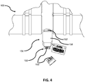
FIG. 4 is a side elevation view of a splicing cable connector with a cut-through sacrificial appendage of the present invention. -
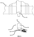
FIG. 5 is a side elevation view of a splicing cable connector with a removed cut-through sacrificial appendage of the present invention. -
FIG. 6 is a side elevation view of a ground rod of the present invention. -
FIG. 7 is a side elevation view of a ground rod with a molded cap of the present invention. -
FIG. 8 is a side elevation view of a ground rod being installed on a sacrificial appendage connection portion and connected to system ground of the present invention. -
FIG. 9 is a side elevation view of a ground rod with a molded cap being installed on a sacrificial appendage connection portion and connected to system ground of the present invention. -
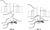
FIG. 10 is a side elevation view of a new, intact sacrificial appendage being installed on a sacrificial appendage connection portion of the present invention. -
FIG. 11 is a side elevation view of a new, intact sacrificial appendage which has been installed on a sacrificial appendage connection portion of the present invention. -
FIG. 12 is a flowchart showing a sequence of events to properly use a sacrificial appendage of the present invention. - The above and other features, aspects and advantages of the present invention will now be discussed in the following detailed description of preferred embodiments and appended claims, which are to be considered in conjunction with the accompanying drawings in which identical reference characters designate like elements throughout the views.
- Shown in
FIG. 1 is a cross-sectional diagram illustrating a powercable splicing connector 100 configured in a manner consistent with the implementations described herein. As shown inFIG. 1 , powercable splicing connector 100 may include a four-way yoke 102 for enabling connection of power cables 104-1, 104-2, 104-3 and 104-4 (collectively "power cables 104," and individually "power cable 104-x"). For example, power cable 104-1 may be a supply cable and cables 104-2 to 104-4 may be load cables. Other types of power cable splicing connectors may be configured in accordance with implementations described herein, such as three-way yoke connectors, two-way yoke connectors, etc. - In one implementation,
yoke 102 of powercable splicing connector 100 may include acentral conductor 106 and a number of splice openings 108-1 to 108-4 (collectively "splice openings 108," and individually "splice opening 108-x").Central conductor 106 may be formed of a suitably conductive material, such as copper, aluminum or other conductive alloy. Further, as shown inFIG. 1 ,central conductor 106 may include outwardly extending portions 110-1 to 110-4 (collectively "outwardly extending portions 110," and individually "outwardly extending portion 110-x") that project from respective splice openings 108-x. As described in additional detail below,central conductor 106 may connect each of power cables 104-x to each other power cable 104-x, such that voltage applied to one cable is transferred to each other cable. - Outwardly extending portions 110 may be configured to receive connector portions of power cables 104. For example, each extending portion 110-x may include a
spade portion 111 having a threadedbore 112 therein for receiving aconnector bolt 114. In one configuration, as illustrated inFIG. 1 , outwardly extending portion 110-1 extends oppositely from outwardly extending portion 110-2 and outwardly extending portion 110-3 extends oppositely from outwardly extending portion 110-4. Furthermore, outwardly extending portions 110-1 and 110-2 may be oriented parallel to outwardly extending portions 110-3 and 110-4, respectively. Such a configuration may provide for compact splicing or splitting of a power supply cable (e.g., cable 104-1) to multiple load cables (e.g., cables 104-2 to 104-4). - As shown in
FIG. 1 , each splice opening 108-x includes a cable receptacle interface that includes a substantially cylindrical flange or cuff portion configured to frictionally engage a cable receptacle 116-x (individually, cable receptacle 116-x, or collectively, cable receptacles 116). For example, an inside diameter of a forward end of cable receptacle 1166x may be sized to frictionally engage the cuff portion of splice opening 108-x. Each cable receptacle 116-x may be substantially cylindrical and may be configured to surround and protect an interface between power cables 104 and extending portions 110. - Yoke 102 may include an
outer shield 120 formed from, for example, a peroxide-cured synthetic rubber, commonly referred to as EPDM (ethylene-propylene-diene monomer). Withinshield 120,yoke 102 may included an insulativeinner housing 122, typically molded from an insulative rubber or epoxy material.Central conductor 106 may be enclosed within insulativeinner housing 122. - Regarding cable receptacles 116, each cable receptacle 116-x may include an EPDM
outer shield 124 and an insulative inner housing 126, typically molded from an insulative rubber or epoxy material. Cable receptacle 116-x further includes a conductive orsemi-conductive insert 128 having a bore there through. Upon assembly, cable receptacle 116-x surrounds the interface between power cable 104-x and outwardly extending portion 110-x. In one implementation, a forward end ofinsert 128 may be configured to frictionally engage outwardly extending portion 110-x ofcentral conductor 106 upon assembly ofsplicing connector 100, thereby ensuring the electrical integrity ofsplicing connector 100. - Referring to power cables 104, a forward end of each power cable 104-x may be prepared by connecting power cable 104-x to a
crimp connector 130.Crimp connector 130 may include a substantially cylindrical assembly configured to receive acable conductor 132 of power cable 104-x therein. During preparing of power cable 104-x, a portion ofcrimp connector 130 may be physically deformed (e.g., crimped) to fastencrimp connector 130 tocable conductor 132.Crimp connector portion 130 may include a forward spade portion 134 configured to be securely fastened to thespade portion 111 of outwardly extending portion 110-x ofcentral conductor 106. For example, forward spade portion 134 may include a bore (not shown) configured to align withbore 112 inspade portion 111.Connector bolt 114 may be inserted through the bore and into threadedbore 112 during assembly ofsplice connector 100. - As shown in
FIG. 1 , each of the prepared power cables 104 may further include anadapter 138 disposed rearwardly relative to crimpconnector 130.Adapter 138 may be affixed to power cable 104-x and may provide a frictional engagement with a rearward portion of cable receptacle 116-x. In one implementation,adapter 138 may be formed of an insulative material, such as rubber or epoxy. - Consistent with implementations described herein,
yoke 102 may include asacrificial appendage 148 projecting there-from. In one implementation,sacrificial appendage 148 may project substantially perpendicularly from outwardly extending portions 110, so as to be relatively free of encumbrances. When it is necessary for work to be performed on any of power cables 104 (or devices connected to power cables 104), a worker may cut through sacrificial appendage 148 (e.g., with a hydraulic cable cutter, or similar tool) to ensure that the electrical system that thesplicing connector 100 is connected to has been properly de-energized and is, therefore, safe to work on. Once thesacrificial appendage 148 has been cut, and a portion (to be described in detail below) has been removed, a sacrificialappendage connection portion 152 is then exposed projecting outwardly from yoke 102 (seeFIG. 5 ). In one implementation, sacrificialappendage connection portion 152 may be integrally formed withinner housing 122 and may include acontact 154 provided therein. Contact 154 may extend into a corresponding portion ofcentral conductor 106, such as via a threaded bore provided incentral conductor 106. Contact 154 may include afemale thread 155 at an outer end thereof for receiving asacrificial cap 156 and for receiving aground rod 151 for grounding the system, to be described below. - As shown in
FIG. 1 ,sacrificial cap 156 may include an EPDMouter shield 158 and an insulativeinner housing 160, typically molded from an insulative rubber or epoxy material.Sacrificial cap 156 may further include asacrificial conductor 162 received within a rearward portion ofinner housing 160. Furthermore, a forward portion ofsacrificial cap 156 may include acavity 164 therein, shown inFIG. 2 , for engaging a projecting portion of sacrificialappendage connection portion 152. - A forward portion of
outer shield 158 andinner housing 160 may be configured to surround and protect an interface between sacrificialappendage connection portion 152 andsacrificial conductor 162. In one implementation, a forward end ofouter shield 158 andinner housing 160 may be configured to frictionally engage a stepped or notched outer configuration of sacrificialappendage connection portion 152 upon assembly ofsplicing connector 100, thereby ensuring the electrical integrity ofsplicing connector 100. - Consistent with implementations described herein,
sacrificial conductor 162 may include a conductive threadedmale protrusion 166 extending axially there-from. As described above, the projecting portion ofcontact 154 of sacrificialappendage connection portion 152 may include threadedfemale cavity 155.Male protrusion 166 may correspond to threadedfemale portion 155 incontact 154 to couple contact 154 tosacrificial conductor 162, thereby conductively connectingsacrificial conductor 162 tocentral conductor 106 ofyoke 102. In other implementations, the male/female relationship may be reversed. - In one implementation, a cut-through
region 168 may be provided in an outer portion ofsacrificial cap 156 in a region overlying at least a portion ofsacrificial conductor 162, as shown inFIG. 2 . In some implementations,indicia 169 relating to cut-throughregion 168 may be provided on a surface ofouter shield 158, shown inFIG. 3 , for indicating that a user is to cut throughsacrificial cap 156 at cut-throughregion 168. - When it is necessary for work to be performed on any of power cables 104 (or devices connected to power cables 104), a worker may cut through
sacrificial cap 156 at cut-through region 168 (e.g., with a grounded hydraulic cable cutter, or similar tool) to ensure that the electrical system that splicingconnector 100 is connected to has been properly de-energized, and is, therefore, safe to work on. When it is time to re-energizesplicing connector 100, the cut-throughsacrificial cap 156 may be discarded and a new or replacementsacrificial cap 156 may be installed, as shown inFIGS. 10 and 11 . - After the
sacrificial cap 156 has been cut at the cut-throughregion 168, shown inFIG. 4 , to ensure that the system has been properly de-energized, a worker must then connect the system to system ground in order for thesplicing connector 100 to be safely serviced. Rather than disassembling a leg of thesplicing connector 100, as is the current method to connect the system to system ground, the sacrificialappendage connection portion 152 and its corresponding threadedfemale cavity 155 can accept a ground rod 151 (once the cut-throughsacrificial cap 156 has been removed, as shown inFIG. 5 ) as a convenient way of grounding the system without having to disassemble thesplicing connector 100 and having to connect a grounding device to one of the legs of the splicing connector. Theground rod 151, as shown inFIGS. 6 and 7 , may or may not have an EPDM moldedcap 149 on its end which connects to sacrificialappendage connection portion 152. If aground rod 151 is used which has the moldedcap 149, then thecap 149 covers the interface between theground rod 151 and the sacrificialappendage connection portion 152. Regardless of whether theground rod 151 has the moldedcap 149 or not, theground rod 151 is comprised of a threadedmale protrusion 153 on its end which connects to sacrificialappendage connection portion 152, which thereby corresponds to the threadedfemale cavity 155 as described above. Because the threadedfemale cavity 155 is part of thecontact 154 which extends into a corresponding portion ofcentral conductor 106, as shown inFIG. 1 , this allows for theground rod 151 to be mechanically and conductively coupled to thesplicing connector 100 when the ground rod is attached to theconnection portion 152. Once theground rod 151 is securely attached to the sacrificialappendage connection portion 152, a worker may connect a grounding device, such as a grounding clamp, toground rod 151 to ensure that thesplicing connector 100 is properly connected to system ground so that it may be safely serviced. - Shown in
FIGS. 8 and9 are two types of grounding devices which can be attached toground rod 151 in order to connectsplicing connector 100 and any attached cables to system ground.FIG. 8 shows theground rod 151 without the moldedcap 149 andFIG. 9 shows the ground rod with the moldedcap 149, as previously described. Both figures show a bartype grounding clamp 172 and a balltype grounding clamp 170. The balltype grounding clamp 170 attaches to aball end 157 ofground rod 151. The bartype grounding clamp 172 attaches to amiddle portion 159 ofground rod 151. Either type ofgrounding clamp splicing connector 100 to system ground. It is assumed that before theground rod 151 was installed in the sacrificialappendage connection portion 152, the entire system was de-energized, which was confirmed by cutting through the sacrificial appendage cut-throughregion 168, as shown inFIG. 4 and described above, so that a worker could safely service thesplicing connector 100. In both implementations shown inFIGS. 8 and9 , thegrounding clamp splicing connector 100 and any attached cables once theground clamp ground rod 151. Though ground clamps 170 and 172 are the only two grounding devices shown, it is understood that other types of grounding devices may be available to attach toground rod 151 in order to achieve the purpose of connectingsplicing connector 100 to system ground. - After a worker is finished servicing the grounded
splicing connector 100 and any attached cables, they may then remove theground clamp ground rod 151. Theground rod 151 may then be removed from the sacrificialappendage connection portion 152 by unscrewing the threadedmale protrusion 153 from the threadedfemale cavity 155, and a new and intactsacrificial cap 156 may be installed on sacrificialappendage connection portion 152, connecting to sacrificialappendage connection portion 152 as described above. The placement of a new, intactsacrificial cap 156 is shown inFIGS. 10 and 11 . Once the new, intactsacrificial cap 156 is securely installed, the system may be safely energized once again. The above described invention allows for a quick and convenient manner of detecting whether or not a system has been de-energized and a way to safely and conveniently ground that same system. - Lastly, shown in
FIG. 12 is a flowchart showing a sequence of events to properly use thesacrificial appendage 148 andground rod 151 of thesplicing connector 100 described above. The flowchart illustrates the following steps: providing thesplicing connector 100 which is comprised of a sacrificialappendage connection portion 152 for asacrificial appendage 148 that is conductively connected to thesplicing connector 100, confirming that thesplicing connector 100 and any equipment conductively coupled to theconnector 100 is de-energized by cutting through the cut-throughregion 168 of thesacrificial appendage 148, removing the cut-throughsacrificial appendage 148, replacing the cut-throughsacrificial appendage 148 with aground rod 151 which is releasably retained within the sacrificialappendage connection portion 152, connecting agrounding clamp ground rod 151, performing service on thesplicing connector 100 or on equipment conductively coupled to thesplicing connector 100, disconnecting thegrounding clamp ground rod 151, removing theground rod 151 from the sacrificialappendage connection portion 152, replacing theground rod 151 with a new, intactsacrificial appendage 148 and re-energizing thesplicing connector 100 and any equipment conductively coupled to theconnector 100.
Claims (11)
- An electrical connector (100), comprising:a yoke (102) comprised of an outer housing (120) and a central conductor (106) within the outer housing (120), wherein the yoke (102) can be connected to at least one cable (104);a sacrificial appendage (148) releasably retained within the yoke (102) and in conductive contact with the yoke central conductor (106), the sacrificial appendage (148) configured to be cut through in order to confirm that the electrical connector (100) is de-energized;wherein after cutting the sacrificial appendage (148), the sacrificial appendage (148) is removable from the yoke (102), characterized in that:after removing the sacrificial appendage (148), a releasably retained ground rod (151) is mounted to the yoke (102) in place of the sacrificial appendage (148) and in conductive contact with the central conductor (106), wherein the ground rod (151) is configured to be connectable to system ground to ground the electrical connector (100) to allow at least one cable (104) or circuit connectable thereto to be serviced;wherein after service is completed, the ground rod (151) is removed from the yoke (102) and replaced with a new, intact sacrificial appendage (148) which is releasably retained within the yoke (102) and which is mechanically and conductively connected to the central conductor (106) so that the electrical connector may be re-energized.
- The electrical connector (100) of claim 1, wherein the yoke (102) comprises a two-way yoke, a three-way yoke, or a four-way yoke.
- The electrical connector (100) of claim 1 or claim 2, wherein the ground rod (151) further comprises a rounded ball end (157) on an outwardly extending portion of the ground rod (151) which extends from the outer housing (120) of the yoke (102) for attachment to a ball type grounding clamp (170).
- The electrical connector (100) of any preceding claim, wherein the ground rod (151) further comprises a middle elongate portion (159) of the ground rod (151) for attachment to a bar type grounding clamp (172).
- The electrical connector (100) of any preceding claim, wherein the central conductor (106) comprises at least three outwardly extending portions (110) which are comprised of a first outwardly extending portion and a second outwardly extending portion of the central conductor (106) which can be operatively coupled to first and second power cables (104), respectively, and a third outwardly extending portion of the central conductor which is comprised of the sacrificial appendage (148).
- The electrical connector (100) of claim 5, wherein the sacrificial appendage (148) comprises a sacrificial cap (156), and wherein the yoke (102) is configured to releasably retain the sacrificial cap (156) in conductive contact with the third outwardly extending portion.
- The electrical connector (100) of claim 6, wherein the third outwardly extending portion further comprises a sacrificial interface (154) conductively coupled to the third outwardly extending portion, and wherein the sacrificial interface (154) is configured to releasably receive the sacrificial cap (156) thereon.
- The electrical connector (100) of claim 7, wherein the sacrificial cap (156) further comprises an insulative inner housing (160) and a sacrificial conductor (162) extending axially within the housing (120), and wherein the housing (120) includes a cut-through region overlying the sacrificial conductor (162), and wherein the sacrificial conductor (162), and the sacrificial cap (156) within which it is housed, is configured for releasable attachment to the sacrificial interface (154).
- The electrical connector (100) of any one of claims 5 to 8, further comprising a first cable receptacle (116-1) for providing an interface between the first outwardly extending portion (110-1) and the first power cable (104-1), and a second cable receptacle (116-2) for providing an interface between the second outwardly extending portion (110-2) and the second power cable (104-2), wherein the first and second cable receptacles (116-1, 116-2) are configured for engagement with the outer housing (120) of the yoke (102).
- The electrical connector (100) of any one of claims 5 to 9, wherein each of the first outwardly extending portion (110-1) and the second outwardly extending portion (110-2) further comprise a spade portion (111) for connecting to the first and second power cables (104-1, 104-2), respectively.
- The electrical connector (100) of claim 10, further comprising first and second crimp connectors (130) coupled to the first and second power cables (104-1, 104-2), respectively, and wherein the first and second crimp connectors (130) are configured for securing to the spade portions (111) of the first and second outwardly extending portions (110-1, 110-2), respectively.
Applications Claiming Priority (2)
| Application Number | Priority Date | Filing Date | Title |
|---|---|---|---|
| US201361897542P | 2013-10-30 | 2013-10-30 | |
| US14/511,452 US9337553B2 (en) | 2013-10-30 | 2014-10-10 | Grounding rod for sacrificial appendage |
Publications (3)
| Publication Number | Publication Date |
|---|---|
| EP2869401A1 EP2869401A1 (en) | 2015-05-06 |
| EP2869401B1 true EP2869401B1 (en) | 2018-03-07 |
| EP2869401B8 EP2869401B8 (en) | 2018-04-18 |
Family
ID=51842379
Family Applications (1)
| Application Number | Title | Priority Date | Filing Date |
|---|---|---|---|
| EP14190650.3A Active EP2869401B8 (en) | 2013-10-30 | 2014-10-28 | Grounding rod for sacrificial appendage |
Country Status (8)
| Country | Link |
|---|---|
| US (1) | US9337553B2 (en) |
| EP (1) | EP2869401B8 (en) |
| CN (1) | CN104600507B (en) |
| AU (1) | AU2014250615B2 (en) |
| BR (1) | BR102014026701A2 (en) |
| CA (1) | CA2867397C (en) |
| ES (1) | ES2673048T3 (en) |
| MX (1) | MX340279B (en) |
Families Citing this family (1)
| Publication number | Priority date | Publication date | Assignee | Title |
|---|---|---|---|---|
| WO2017083385A1 (en) * | 2015-11-09 | 2017-05-18 | Thomas & Belts International Llc | Electrical connector having a sacrificial cap and integrated test point |
Family Cites Families (65)
| Publication number | Priority date | Publication date | Assignee | Title |
|---|---|---|---|---|
| US1902617A (en) | 1929-02-06 | 1933-03-21 | Westinghouse Electric & Mfg Co | High-voltage bushing device |
| US2941834A (en) | 1956-05-25 | 1960-06-21 | Greer Marine Corp | Locking mechanism |
| US2937359A (en) | 1956-05-31 | 1960-05-17 | Gen Electric | Power factor tap for high voltage bushing |
| US3343153A (en) | 1965-12-03 | 1967-09-19 | Mc Graw Edison Co | Cable connector having means for indicating when cable is energized |
| US3390331A (en) | 1966-03-21 | 1968-06-25 | Elastic Stop Nut Corp | Device for detecting the presence of voltage in connectors of high voltage systems |
| US3363171A (en) | 1966-06-17 | 1968-01-09 | Vernon H. Sietmann | Electrical circuit tester with insulation piercing probe means |
| US3915534A (en) | 1967-08-15 | 1975-10-28 | Joslyn Mfg & Supply Co | Grounded surface distribution apparatus |
| US3835439A (en) | 1967-08-15 | 1974-09-10 | Joslyn Mfg & Supply Co | Grounded surface distribution apparatus |
| US3740700A (en) | 1972-05-11 | 1973-06-19 | E Robertson | Safety connector |
| US3924919A (en) | 1972-12-15 | 1975-12-09 | Esco Mfg Co | Disconnectable electrical connector |
| US3853375A (en) | 1972-12-15 | 1974-12-10 | Esco Mfg Co | Electrical connector apparatus disconnectable link assembly |
| US3883208A (en) | 1973-10-25 | 1975-05-13 | Rte Corp | Visible break tee-connector |
| US3959869A (en) | 1974-03-29 | 1976-06-01 | Amerace Corporation | Apparatus for the remote grounding, connection and disconnection of high voltage electrical circuits |
| US3980374A (en) | 1975-02-26 | 1976-09-14 | International Telephone And Telegraph Corporation | Separable splice connector |
| US4152643A (en) | 1978-04-10 | 1979-05-01 | E. O. Schweitzer Manufacturing Co., Inc. | Voltage indicating test point cap |
| US4202591A (en) | 1978-10-10 | 1980-05-13 | Amerace Corporation | Apparatus for the remote grounding, connection and disconnection of high voltage electrical circuits |
| US4272798A (en) | 1979-10-25 | 1981-06-09 | Westinghouse Electric Corp. | Composite groundable barrier for switchgear and grounding apparatus |
| GB2154382B (en) | 1983-12-14 | 1988-04-07 | Raychem Ltd | High voltage connector |
| US4660909A (en) | 1985-12-16 | 1987-04-28 | Wilson Daniel P | Remote grounding device for subterranean power systems |
| US4760327A (en) | 1986-11-10 | 1988-07-26 | Boston Edison Company | Cable status testing |
| US4787855A (en) | 1987-06-05 | 1988-11-29 | Houston Industries Incorporated | Multiple bushing connector apparatus |
| US4904932A (en) | 1987-06-16 | 1990-02-27 | E. O. Schweitzer Manufacturing Co., Inc. | Circuit condition monitor with integrally molded test point socket and capacitive coupling |
| US4744765A (en) | 1987-06-19 | 1988-05-17 | John DeLeo | High voltage ground stud |
| US4799895A (en) | 1987-06-22 | 1989-01-24 | Amerace Corporation | 600-Amp hot stick operable screw-assembled connector system |
| US4822289A (en) | 1987-10-02 | 1989-04-18 | Deleo John | Easily removable high voltage ground stud insulator |
| US4859192A (en) | 1987-10-02 | 1989-08-22 | Deleo John | Easily removable high voltage ground stud insulator |
| US4794331A (en) | 1987-10-30 | 1988-12-27 | Schweitzer Edmund O Jun | Circuit condition monitoring system having integral test point |
| US4946393A (en) | 1989-08-04 | 1990-08-07 | Amerace Corporation | Separable connector access port and fittings |
| US5082449A (en) * | 1990-08-28 | 1992-01-21 | Amerace Corporation | Removable media injection fitting |
| US5114357A (en) | 1991-04-29 | 1992-05-19 | Amerace Corporation | High voltage elbow |
| US5131855A (en) | 1991-05-29 | 1992-07-21 | Westinghouse Electric Corp. | Grounding stud assembly |
| US5367251A (en) | 1993-01-19 | 1994-11-22 | Mctigue James F | Tool for grasping and piercing insulated electrical cable for determining whether conductor of cable is energized |
| US5450280A (en) | 1994-01-18 | 1995-09-12 | Powell Electrical Manufacturing Company | Voltage transformer disconnect grounding system |
| US6075209A (en) | 1997-01-15 | 2000-06-13 | Thomas & Betts International | Insulated cap for loadbreak bushing |
| US6332785B1 (en) | 1997-06-30 | 2001-12-25 | Cooper Industries, Inc. | High voltage electrical connector with access cavity and inserts for use therewith |
| US6210206B1 (en) | 1999-08-03 | 2001-04-03 | Roland G. Durham | Safety shield spiking tool and method for spiking high voltage power lines |
| US6649840B2 (en) | 2001-01-22 | 2003-11-18 | Thomas & Betts International, Inc. | Ground bus bar connector |
| US20040160227A1 (en) | 2003-02-18 | 2004-08-19 | Piesinger Gregory H. | Apparatus and method for determining the status of an electric power cable |
| US6843685B1 (en) | 2003-12-24 | 2005-01-18 | Thomas & Betts International, Inc. | Electrical connector with voltage detection point insulation shield |
| CA2454445C (en) | 2003-12-24 | 2007-05-29 | Thomas & Betts International, Inc. | Electrical connector with voltage detection point insulation shield |
| US7212389B2 (en) | 2005-03-25 | 2007-05-01 | Cooper Technologies Company | Over-voltage protection system |
| US7381103B2 (en) | 2005-04-01 | 2008-06-03 | Richards Manufacturing Company | Multiple bore termination system having an integrally formed component |
| US7288718B2 (en) | 2005-10-24 | 2007-10-30 | Thomas & Betts International, Inc. | Separable electrical connector component for sending and receiving communication signals through underground power distribution lines |
| US7572133B2 (en) | 2005-11-14 | 2009-08-11 | Cooper Technologies Company | Separable loadbreak connector and system |
| MXPA06014816A (en) | 2005-12-21 | 2008-10-16 | Thomas & Betts Int | Separable electrical connector component having a voltage output branch and a direct access point . |
| US7568927B2 (en) | 2007-04-23 | 2009-08-04 | Cooper Technologies Company | Separable insulated connector system |
| US7462776B1 (en) | 2007-06-01 | 2008-12-09 | Lightning Eliminators & Consultants, Inc. | Low impedance grounding electrode with universal connections and rapid access cap |
| US7661979B2 (en) | 2007-06-01 | 2010-02-16 | Cooper Technologies Company | Jacket sleeve with grippable tabs for a cable connector |
| US7695291B2 (en) | 2007-10-31 | 2010-04-13 | Cooper Technologies Company | Fully insulated fuse test and ground device |
| US8056226B2 (en) * | 2008-02-25 | 2011-11-15 | Cooper Technologies Company | Method of manufacturing a dual interface separable insulated connector with overmolded faraday cage |
| US7958631B2 (en) * | 2008-04-11 | 2011-06-14 | Cooper Technologies Company | Method of using an extender for a separable insulated connector |
| US7708576B2 (en) | 2008-08-25 | 2010-05-04 | Cooper Industries, Ltd. | Electrical connector including a ring and a ground shield |
| US7942679B1 (en) | 2008-10-07 | 2011-05-17 | Arlington Industries, Inc. | Grounding terminal block assembly including conduit adapter for multiple services |
| JP2010153268A (en) * | 2008-12-26 | 2010-07-08 | D D K Ltd | Ground structure and electrical connector using the ground structure |
| DE202009007276U1 (en) | 2009-05-22 | 2010-10-14 | Weidmüller Interface GmbH & Co. KG | Connector for transmitting high electrical power |
| US8368405B2 (en) * | 2009-07-30 | 2013-02-05 | Thomas & Betts International, Inc. | Remote test point for electrical connector |
| US8172596B2 (en) | 2010-03-03 | 2012-05-08 | Thomas & Betts International, Inc. | Electrical connector with sacrificial appendage |
| US9124015B2 (en) | 2010-03-03 | 2015-09-01 | Thomas & Betts International Llc | Electrical connector with sacrificial appendage and a grounding element |
| US8616908B2 (en) | 2010-03-03 | 2013-12-31 | Thomas & Betts International, Inc. | Electrical connector with a cap with a sacrificial conductor |
| US8597040B2 (en) | 2010-03-03 | 2013-12-03 | Thomas & Betts International, Inc. | Device having an electrical connector and a sacrificial cap |
| US7901243B1 (en) | 2010-03-30 | 2011-03-08 | Tyco Electronics Corporation | Methods and systems for forming a protected disconnectable joint assembly |
| US8388381B2 (en) | 2010-07-21 | 2013-03-05 | Thomas & Betts International, Inc. | Visible open for switchgear assembly |
| US8128423B2 (en) | 2010-07-29 | 2012-03-06 | Thomas & Betts International, Inc. | Visible open for switchgear assembly |
| US8454376B1 (en) | 2011-11-10 | 2013-06-04 | Thomas & Betts International, Inc. | Electrical connector with sacrificial component |
| US9124050B2 (en) | 2012-07-19 | 2015-09-01 | Thomas & Betts International Llc | Electrical connector having grounding mechanism |
-
2014
- 2014-10-10 US US14/511,452 patent/US9337553B2/en active Active
- 2014-10-14 AU AU2014250615A patent/AU2014250615B2/en not_active Ceased
- 2014-10-15 CA CA2867397A patent/CA2867397C/en active Active
- 2014-10-24 BR BR102014026701A patent/BR102014026701A2/en not_active Application Discontinuation
- 2014-10-28 EP EP14190650.3A patent/EP2869401B8/en active Active
- 2014-10-28 ES ES14190650.3T patent/ES2673048T3/en active Active
- 2014-10-30 CN CN201410756028.8A patent/CN104600507B/en active Active
- 2014-10-30 MX MX2014013230A patent/MX340279B/en active IP Right Grant
Non-Patent Citations (1)
| Title |
|---|
| None * |
Also Published As
| Publication number | Publication date |
|---|---|
| MX340279B (en) | 2016-07-04 |
| US9337553B2 (en) | 2016-05-10 |
| US20150118892A1 (en) | 2015-04-30 |
| CN104600507A (en) | 2015-05-06 |
| CA2867397A1 (en) | 2015-04-30 |
| CA2867397C (en) | 2016-11-29 |
| MX2014013230A (en) | 2015-04-30 |
| CN104600507B (en) | 2018-08-21 |
| EP2869401B8 (en) | 2018-04-18 |
| EP2869401A1 (en) | 2015-05-06 |
| ES2673048T3 (en) | 2018-06-19 |
| BR102014026701A2 (en) | 2016-09-27 |
| AU2014250615A1 (en) | 2015-05-14 |
| AU2014250615B2 (en) | 2019-03-07 |
Similar Documents
| Publication | Publication Date | Title |
|---|---|---|
| US8172596B2 (en) | Electrical connector with sacrificial appendage | |
| EP2854240B1 (en) | Permanent ground point for splicing connectors | |
| EP3021424B1 (en) | Electrical connector assembly comprising a grounding link and corresponding method of connection | |
| US8597040B2 (en) | Device having an electrical connector and a sacrificial cap | |
| US10845392B2 (en) | Electrical connector having a sacrificial cap and integrated test point | |
| US8454376B1 (en) | Electrical connector with sacrificial component | |
| US8616908B2 (en) | Electrical connector with a cap with a sacrificial conductor | |
| EP2869401B1 (en) | Grounding rod for sacrificial appendage | |
| US9124015B2 (en) | Electrical connector with sacrificial appendage and a grounding element | |
| EP2871719B1 (en) | Electrical connector with sacrificial appendage | |
| CA2733112C (en) | Electrical connector with sacrificial appendage | |
| CA2776706C (en) | Electrical connector with sacrificial appendage | |
| EP2685563B1 (en) | Restraint and lock for electrical connector | |
| CA2776783C (en) | Electrical connector with sacrificial appendage | |
| CA2766633C (en) | Electrical connector with sacrificial component |
Legal Events
| Date | Code | Title | Description |
|---|---|---|---|
| PUAI | Public reference made under article 153(3) epc to a published international application that has entered the european phase |
Free format text: ORIGINAL CODE: 0009012 |
|
| 17P | Request for examination filed |
Effective date: 20141028 |
|
| AK | Designated contracting states |
Kind code of ref document: A1 Designated state(s): AL AT BE BG CH CY CZ DE DK EE ES FI FR GB GR HR HU IE IS IT LI LT LU LV MC MK MT NL NO PL PT RO RS SE SI SK SM TR |
|
| AX | Request for extension of the european patent |
Extension state: BA ME |
|
| R17P | Request for examination filed (corrected) |
Effective date: 20151103 |
|
| RBV | Designated contracting states (corrected) |
Designated state(s): AL AT BE BG CH CY CZ DE DK EE ES FI FR GB GR HR HU IE IS IT LI LT LU LV MC MK MT NL NO PL PT RO RS SE SI SK SM TR |
|
| 17Q | First examination report despatched |
Effective date: 20161212 |
|
| GRAP | Despatch of communication of intention to grant a patent |
Free format text: ORIGINAL CODE: EPIDOSNIGR1 |
|
| INTG | Intention to grant announced |
Effective date: 20170920 |
|
| GRAS | Grant fee paid |
Free format text: ORIGINAL CODE: EPIDOSNIGR3 |
|
| GRAA | (expected) grant |
Free format text: ORIGINAL CODE: 0009210 |
|
| AK | Designated contracting states |
Kind code of ref document: B1 Designated state(s): AL AT BE BG CH CY CZ DE DK EE ES FI FR GB GR HR HU IE IS IT LI LT LU LV MC MK MT NL NO PL PT RO RS SE SI SK SM TR |
|
| REG | Reference to a national code |
Ref country code: GB Ref legal event code: FG4D |
|
| REG | Reference to a national code |
Ref country code: CH Ref legal event code: EP Ref country code: AT Ref legal event code: REF Ref document number: 977494 Country of ref document: AT Kind code of ref document: T Effective date: 20180315 |
|
| RAP2 | Party data changed (patent owner data changed or rights of a patent transferred) |
Owner name: THOMAS & BETTS INTERNATIONAL LLC |
|
| REG | Reference to a national code |
Ref country code: IE Ref legal event code: FG4D |
|
| REG | Reference to a national code |
Ref country code: DE Ref legal event code: R096 Ref document number: 602014021912 Country of ref document: DE |
|
| REG | Reference to a national code |
Ref country code: ES Ref legal event code: FG2A Ref document number: 2673048 Country of ref document: ES Kind code of ref document: T3 Effective date: 20180619 |
|
| REG | Reference to a national code |
Ref country code: SE Ref legal event code: TRGR |
|
| REG | Reference to a national code |
Ref country code: NL Ref legal event code: MP Effective date: 20180307 |
|
| REG | Reference to a national code |
Ref country code: LT Ref legal event code: MG4D |
|
| PG25 | Lapsed in a contracting state [announced via postgrant information from national office to epo] |
Ref country code: CY Free format text: LAPSE BECAUSE OF FAILURE TO SUBMIT A TRANSLATION OF THE DESCRIPTION OR TO PAY THE FEE WITHIN THE PRESCRIBED TIME-LIMIT Effective date: 20180307 Ref country code: NO Free format text: LAPSE BECAUSE OF FAILURE TO SUBMIT A TRANSLATION OF THE DESCRIPTION OR TO PAY THE FEE WITHIN THE PRESCRIBED TIME-LIMIT Effective date: 20180607 Ref country code: FI Free format text: LAPSE BECAUSE OF FAILURE TO SUBMIT A TRANSLATION OF THE DESCRIPTION OR TO PAY THE FEE WITHIN THE PRESCRIBED TIME-LIMIT Effective date: 20180307 Ref country code: HR Free format text: LAPSE BECAUSE OF FAILURE TO SUBMIT A TRANSLATION OF THE DESCRIPTION OR TO PAY THE FEE WITHIN THE PRESCRIBED TIME-LIMIT Effective date: 20180307 Ref country code: LT Free format text: LAPSE BECAUSE OF FAILURE TO SUBMIT A TRANSLATION OF THE DESCRIPTION OR TO PAY THE FEE WITHIN THE PRESCRIBED TIME-LIMIT Effective date: 20180307 |
|
| REG | Reference to a national code |
Ref country code: AT Ref legal event code: MK05 Ref document number: 977494 Country of ref document: AT Kind code of ref document: T Effective date: 20180307 |
|
| PG25 | Lapsed in a contracting state [announced via postgrant information from national office to epo] |
Ref country code: LV Free format text: LAPSE BECAUSE OF FAILURE TO SUBMIT A TRANSLATION OF THE DESCRIPTION OR TO PAY THE FEE WITHIN THE PRESCRIBED TIME-LIMIT Effective date: 20180307 Ref country code: BG Free format text: LAPSE BECAUSE OF FAILURE TO SUBMIT A TRANSLATION OF THE DESCRIPTION OR TO PAY THE FEE WITHIN THE PRESCRIBED TIME-LIMIT Effective date: 20180607 Ref country code: RS Free format text: LAPSE BECAUSE OF FAILURE TO SUBMIT A TRANSLATION OF THE DESCRIPTION OR TO PAY THE FEE WITHIN THE PRESCRIBED TIME-LIMIT Effective date: 20180307 Ref country code: GR Free format text: LAPSE BECAUSE OF FAILURE TO SUBMIT A TRANSLATION OF THE DESCRIPTION OR TO PAY THE FEE WITHIN THE PRESCRIBED TIME-LIMIT Effective date: 20180608 |
|
| PG25 | Lapsed in a contracting state [announced via postgrant information from national office to epo] |
Ref country code: RO Free format text: LAPSE BECAUSE OF FAILURE TO SUBMIT A TRANSLATION OF THE DESCRIPTION OR TO PAY THE FEE WITHIN THE PRESCRIBED TIME-LIMIT Effective date: 20180307 Ref country code: NL Free format text: LAPSE BECAUSE OF FAILURE TO SUBMIT A TRANSLATION OF THE DESCRIPTION OR TO PAY THE FEE WITHIN THE PRESCRIBED TIME-LIMIT Effective date: 20180307 Ref country code: PL Free format text: LAPSE BECAUSE OF FAILURE TO SUBMIT A TRANSLATION OF THE DESCRIPTION OR TO PAY THE FEE WITHIN THE PRESCRIBED TIME-LIMIT Effective date: 20180307 Ref country code: EE Free format text: LAPSE BECAUSE OF FAILURE TO SUBMIT A TRANSLATION OF THE DESCRIPTION OR TO PAY THE FEE WITHIN THE PRESCRIBED TIME-LIMIT Effective date: 20180307 Ref country code: AL Free format text: LAPSE BECAUSE OF FAILURE TO SUBMIT A TRANSLATION OF THE DESCRIPTION OR TO PAY THE FEE WITHIN THE PRESCRIBED TIME-LIMIT Effective date: 20180307 |
|
| PG25 | Lapsed in a contracting state [announced via postgrant information from national office to epo] |
Ref country code: SM Free format text: LAPSE BECAUSE OF FAILURE TO SUBMIT A TRANSLATION OF THE DESCRIPTION OR TO PAY THE FEE WITHIN THE PRESCRIBED TIME-LIMIT Effective date: 20180307 Ref country code: AT Free format text: LAPSE BECAUSE OF FAILURE TO SUBMIT A TRANSLATION OF THE DESCRIPTION OR TO PAY THE FEE WITHIN THE PRESCRIBED TIME-LIMIT Effective date: 20180307 Ref country code: SK Free format text: LAPSE BECAUSE OF FAILURE TO SUBMIT A TRANSLATION OF THE DESCRIPTION OR TO PAY THE FEE WITHIN THE PRESCRIBED TIME-LIMIT Effective date: 20180307 Ref country code: CZ Free format text: LAPSE BECAUSE OF FAILURE TO SUBMIT A TRANSLATION OF THE DESCRIPTION OR TO PAY THE FEE WITHIN THE PRESCRIBED TIME-LIMIT Effective date: 20180307 |
|
| REG | Reference to a national code |
Ref country code: DE Ref legal event code: R097 Ref document number: 602014021912 Country of ref document: DE |
|
| PG25 | Lapsed in a contracting state [announced via postgrant information from national office to epo] |
Ref country code: PT Free format text: LAPSE BECAUSE OF FAILURE TO SUBMIT A TRANSLATION OF THE DESCRIPTION OR TO PAY THE FEE WITHIN THE PRESCRIBED TIME-LIMIT Effective date: 20180709 |
|
| PLBE | No opposition filed within time limit |
Free format text: ORIGINAL CODE: 0009261 |
|
| STAA | Information on the status of an ep patent application or granted ep patent |
Free format text: STATUS: NO OPPOSITION FILED WITHIN TIME LIMIT |
|
| PG25 | Lapsed in a contracting state [announced via postgrant information from national office to epo] |
Ref country code: DK Free format text: LAPSE BECAUSE OF FAILURE TO SUBMIT A TRANSLATION OF THE DESCRIPTION OR TO PAY THE FEE WITHIN THE PRESCRIBED TIME-LIMIT Effective date: 20180307 |
|
| 26N | No opposition filed |
Effective date: 20181210 |
|
| PG25 | Lapsed in a contracting state [announced via postgrant information from national office to epo] |
Ref country code: SI Free format text: LAPSE BECAUSE OF FAILURE TO SUBMIT A TRANSLATION OF THE DESCRIPTION OR TO PAY THE FEE WITHIN THE PRESCRIBED TIME-LIMIT Effective date: 20180307 |
|
| REG | Reference to a national code |
Ref country code: CH Ref legal event code: PL |
|
| PG25 | Lapsed in a contracting state [announced via postgrant information from national office to epo] |
Ref country code: MC Free format text: LAPSE BECAUSE OF FAILURE TO SUBMIT A TRANSLATION OF THE DESCRIPTION OR TO PAY THE FEE WITHIN THE PRESCRIBED TIME-LIMIT Effective date: 20180307 Ref country code: LU Free format text: LAPSE BECAUSE OF NON-PAYMENT OF DUE FEES Effective date: 20181028 |
|
| REG | Reference to a national code |
Ref country code: IE Ref legal event code: MM4A |
|
| PG25 | Lapsed in a contracting state [announced via postgrant information from national office to epo] |
Ref country code: CH Free format text: LAPSE BECAUSE OF NON-PAYMENT OF DUE FEES Effective date: 20181031 Ref country code: LI Free format text: LAPSE BECAUSE OF NON-PAYMENT OF DUE FEES Effective date: 20181031 |
|
| PG25 | Lapsed in a contracting state [announced via postgrant information from national office to epo] |
Ref country code: IE Free format text: LAPSE BECAUSE OF NON-PAYMENT OF DUE FEES Effective date: 20181028 |
|
| PG25 | Lapsed in a contracting state [announced via postgrant information from national office to epo] |
Ref country code: MT Free format text: LAPSE BECAUSE OF NON-PAYMENT OF DUE FEES Effective date: 20181028 |
|
| PG25 | Lapsed in a contracting state [announced via postgrant information from national office to epo] |
Ref country code: TR Free format text: LAPSE BECAUSE OF FAILURE TO SUBMIT A TRANSLATION OF THE DESCRIPTION OR TO PAY THE FEE WITHIN THE PRESCRIBED TIME-LIMIT Effective date: 20180307 |
|
| PG25 | Lapsed in a contracting state [announced via postgrant information from national office to epo] |
Ref country code: HU Free format text: LAPSE BECAUSE OF FAILURE TO SUBMIT A TRANSLATION OF THE DESCRIPTION OR TO PAY THE FEE WITHIN THE PRESCRIBED TIME-LIMIT; INVALID AB INITIO Effective date: 20141028 Ref country code: MK Free format text: LAPSE BECAUSE OF NON-PAYMENT OF DUE FEES Effective date: 20180307 |
|
| PG25 | Lapsed in a contracting state [announced via postgrant information from national office to epo] |
Ref country code: IS Free format text: LAPSE BECAUSE OF FAILURE TO SUBMIT A TRANSLATION OF THE DESCRIPTION OR TO PAY THE FEE WITHIN THE PRESCRIBED TIME-LIMIT Effective date: 20180707 |
|
| PGFP | Annual fee paid to national office [announced via postgrant information from national office to epo] |
Ref country code: GB Payment date: 20231020 Year of fee payment: 10 |
|
| PGFP | Annual fee paid to national office [announced via postgrant information from national office to epo] |
Ref country code: ES Payment date: 20231227 Year of fee payment: 10 |
|
| PGFP | Annual fee paid to national office [announced via postgrant information from national office to epo] |
Ref country code: SE Payment date: 20231019 Year of fee payment: 10 Ref country code: IT Payment date: 20231026 Year of fee payment: 10 Ref country code: FR Payment date: 20231025 Year of fee payment: 10 Ref country code: DE Payment date: 20231020 Year of fee payment: 10 |
|
| PGFP | Annual fee paid to national office [announced via postgrant information from national office to epo] |
Ref country code: BE Payment date: 20231019 Year of fee payment: 10 |