EP2869399A1 - Etalonnage d'un réseau d'antennes - Google Patents
Etalonnage d'un réseau d'antennes Download PDFInfo
- Publication number
- EP2869399A1 EP2869399A1 EP14189948.4A EP14189948A EP2869399A1 EP 2869399 A1 EP2869399 A1 EP 2869399A1 EP 14189948 A EP14189948 A EP 14189948A EP 2869399 A1 EP2869399 A1 EP 2869399A1
- Authority
- EP
- European Patent Office
- Prior art keywords
- antenna
- antennas
- calibration
- frequency
- probes
- Prior art date
- Legal status (The legal status is an assumption and is not a legal conclusion. Google has not performed a legal analysis and makes no representation as to the accuracy of the status listed.)
- Granted
Links
Images

Classifications
-
- G—PHYSICS
- G01—MEASURING; TESTING
- G01R—MEASURING ELECTRIC VARIABLES; MEASURING MAGNETIC VARIABLES
- G01R35/00—Testing or calibrating of apparatus covered by the other groups of this subclass
-
- G—PHYSICS
- G01—MEASURING; TESTING
- G01N—INVESTIGATING OR ANALYSING MATERIALS BY DETERMINING THEIR CHEMICAL OR PHYSICAL PROPERTIES
- G01N21/00—Investigating or analysing materials by the use of optical means, i.e. using sub-millimetre waves, infrared, visible or ultraviolet light
- G01N21/62—Systems in which the material investigated is excited whereby it emits light or causes a change in wavelength of the incident light
- G01N21/63—Systems in which the material investigated is excited whereby it emits light or causes a change in wavelength of the incident light optically excited
-
- G—PHYSICS
- G01—MEASURING; TESTING
- G01S—RADIO DIRECTION-FINDING; RADIO NAVIGATION; DETERMINING DISTANCE OR VELOCITY BY USE OF RADIO WAVES; LOCATING OR PRESENCE-DETECTING BY USE OF THE REFLECTION OR RERADIATION OF RADIO WAVES; ANALOGOUS ARRANGEMENTS USING OTHER WAVES
- G01S7/00—Details of systems according to groups G01S13/00, G01S15/00, G01S17/00
- G01S7/02—Details of systems according to groups G01S13/00, G01S15/00, G01S17/00 of systems according to group G01S13/00
- G01S7/40—Means for monitoring or calibrating
- G01S7/4004—Means for monitoring or calibrating of parts of a radar system
- G01S7/4021—Means for monitoring or calibrating of parts of a radar system of receivers
-
- H—ELECTRICITY
- H01—ELECTRIC ELEMENTS
- H01Q—ANTENNAS, i.e. RADIO AERIALS
- H01Q1/00—Details of, or arrangements associated with, antennas
- H01Q1/40—Radiating elements coated with or embedded in protective material
- H01Q1/405—Radome integrated radiating elements
-
- H—ELECTRICITY
- H01—ELECTRIC ELEMENTS
- H01Q—ANTENNAS, i.e. RADIO AERIALS
- H01Q1/00—Details of, or arrangements associated with, antennas
- H01Q1/42—Housings not intimately mechanically associated with radiating elements, e.g. radome
-
- H—ELECTRICITY
- H01—ELECTRIC ELEMENTS
- H01Q—ANTENNAS, i.e. RADIO AERIALS
- H01Q15/00—Devices for reflection, refraction, diffraction or polarisation of waves radiated from an antenna, e.g. quasi-optical devices
- H01Q15/02—Refracting or diffracting devices, e.g. lens, prism
- H01Q15/08—Refracting or diffracting devices, e.g. lens, prism formed of solid dielectric material
-
- H—ELECTRICITY
- H01—ELECTRIC ELEMENTS
- H01Q—ANTENNAS, i.e. RADIO AERIALS
- H01Q3/00—Arrangements for changing or varying the orientation or the shape of the directional pattern of the waves radiated from an antenna or antenna system
- H01Q3/26—Arrangements for changing or varying the orientation or the shape of the directional pattern of the waves radiated from an antenna or antenna system varying the relative phase or relative amplitude of energisation between two or more active radiating elements; varying the distribution of energy across a radiating aperture
- H01Q3/267—Phased-array testing or checking devices
-
- H—ELECTRICITY
- H01—ELECTRIC ELEMENTS
- H01Q—ANTENNAS, i.e. RADIO AERIALS
- H01Q5/00—Arrangements for simultaneous operation of antennas on two or more different wavebands, e.g. dual-band or multi-band arrangements
- H01Q5/20—Arrangements for simultaneous operation of antennas on two or more different wavebands, e.g. dual-band or multi-band arrangements characterised by the operating wavebands
- H01Q5/22—RF wavebands combined with non-RF wavebands, e.g. infrared or optical
Definitions
- the present description relates generally to antennas and, more particularly, to the calibration of an antenna or an antenna array to take account of disturbances of the radiation related to the environment close to the antenna or antennas. and the reliability of such calibration.
- An array of antennas especially in direction finding, radar scanning, tracking radar, radio guidance, beam monitoring, etc., needs to be calibrated to provide reliable data.
- these antenna arrays are particularly sensitive to their environment and, in particular, to changes in the device carrying the antenna array (generally referred to as a carrier). This is, for example, a building, a vehicle, and more generally any device likely to be equipped with an antenna or an antenna network.
- laboratory calibration is provided in the laboratory, either by emulating the environment close to the network during the calibration measurement. in a controlled environment (for example, an anechoic chamber), or by simulating these disturbances from the near environment by numerical calculations.
- Calibration generally consists in determining corrective coefficients of the response of the network (in amplitude and in phase) when it receives signals in a given direction, for example the ratio between the voltage supplied by each channel and an incident field ( effective height). Calibration is performed over the entire useful frequency band.
- the disturbances that we wish to correct are those related to the carrier of the antenna array (typically another electronic device, another antenna, etc.).
- the calibration of the far-field array response is derived from near-field measurements via a near-field / far-field transform. Calibration is therefore generally performed in a controlled environment (anechoic chamber) on one or more fixed configurations of the environment close to the network.
- US Pat. No. 5,384,458 describes an electromagnetic sensor for a missile and plans to include, inside the missile head (inside the volume defined by the missile envelope and not at the surface of this envelope), several photon sensors.
- One embodiment of the present disclosure aims at overcoming all or part of the disadvantages of antenna calibration systems or antenna arrays.
- Another embodiment of the present description aims at providing a non-invasive calibration system, that is to say that does not add disturbance to those related to the environment close to the antenna or antennas.
- Another embodiment aims to provide a calibration method that overcomes all or part of the disadvantages of the usual solutions.
- Another embodiment aims to propose a particularly easy solution to implement and adapted to different types of antennas or antenna networks.
- One embodiment aims to provide quasi-real-time calibration in the field.
- the system further comprises an excitation laser, by optical fibers, electro-optical probes.
- the system further comprises a device for transmitting a radio signal.
- the electro-optical probes are distributed at regular angular positions.
- the receiver calculates and stores correction coefficients of the signals provided by the antenna or antennas.
- the system comprises several antennas forming an antenna array.
- said receiver interprets, in a calibration phase, the signals retromodulated by the probes to determine signal correction coefficients received by the antenna or antennas.
- the method further comprises a step d) in which correction coefficients are determined to be applied to the signals supplied by the antenna or antennas.
- step c the analysis of step c is performed at the first frequency and at frequencies corresponding to this first frequency, respectively minus and increased by the second frequency.
- steps b and c are performed successively for each of said probes.
- steps a to d are reproduced for several values of the first frequency.
- antenna arrays are traditionally calibrated by simulating the near environment or by measuring in a controlled environment the behavior of the antenna array on the carrier device. For example, for an antenna array carried by a vehicle, the position on the vehicle of a new electronic equipment or metallic element causes disturbances of the antenna network and requires a new calibration. Traditionally, when it is known that the environment will be disturbed by the addition of a new device, a calibration of the antenna array is re-performed according to its carrier.
- Such calibration systems have the drawback of not taking into account changes in the near environment when the antenna array is in a functional environment.
- In-situ calibration is planned by permanently installing a measurement device around the antenna array in a permanent and non-intrusive manner.
- a difficulty in calibrating the antenna array in its functional environment is that the measuring device must not impact the operation of the antenna, that is to say, not disturb its operation outside the phase of the antenna. calibration.
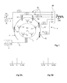
- the figure 1 is a schematic representation of an antenna array equipped with an embodiment of a calibration system.
- an antenna network 1 is assumed.
- the number of antennas varies according to the applications and can be between an antenna and several tens of antennas.
- the antennas 12 are connected (links 14) to an electronic system 2 for operating the signals.
- the antenna array 1 is protected from the outside by means of a radome 3 which constitutes an envelope around the antenna array protecting it from the external elements.
- the constituent material of the radome is chosen so as not to disturb the antenna array.
- the elements described above are the usual elements of an antenna array.
- the radome It is planned to equip the radome with a set of 4 calibration probes 42.
- a special feature of these probes is that they are electro-optical probes each consisting of a photodiode (for example, a non-polarized broadband photodiode) whose electrodes are connected to conductive strands each forming an antenna.
- the probes 42 are individually connected to one or more optical transmission devices 44 by an optical fiber network 46.
- the transmission device 44 is in practice a laser emitting an optical signal at a frequency fm. This signal is used to modulate a radio signal s, unmodulated, transmitted at a frequency fc.
- the signal s is generated by a transmission antenna 5 dedicated to the calibration.
- Each electro-optical probe 42 excited at the frequency fm (for example from a value chosen from a few tens to a few hundred kHz), is less than the frequency fc (for example from a chosen value of a few hundred MHz to a few hundred of GHz), modulates the field backscattered by the probe concerned. Side antennas 12, they capture the result of this modulation. Consequently, the signal exploitation system 2 receives, for each antenna 12, a signal having a spectrum having a main line at the frequency fc, surrounded by lines representing the modulated signal, at the frequencies fc-fm and fc + fm. .
- the signals at the frequencies fc and fc +/- fm are altered with respect to the nominal configuration. They thus contain different information to be analyzed on the new context of the antenna 12.
- the modification (in amplitude and in phase) of the signal at the frequency fc informs on the presence of the disturbing device without being able to deduce the impact on the network in a given angular direction.
- the analysis of the signal at fc +/- fm which comes from the considered probe contains the impact of the disturbing element on each antenna of the network and this only in the direction of the probe (axis probe - antenna considered).
- FIGS. 2A and 2B illustrate, very schematically, examples of spectra of the signal received in the presence of a perturbation in a given direction relative to the antenna network.
- These figures represent two examples of spectrum analyzed by the operating system 2, coming from two separate antennas.
- This example is arbitrary and illustrates that a disturbing element in the near field of the antenna will cause a modification of the module and the phase of the received signal, which differs for each of the antennas as a function of the angular position of the disturbing element .
- the analysis of the signals received in the calibration phase thus makes it possible to identify the disturbing elements and to determine correction coefficients to be applied so that the receiver returns to nominal operation.
- the choice of electro-optical probes associated with the choice of conveying the modulation signal using optical fibers eliminates the disturbing metallic elements of the calibration system, which allows it to remain permanently integrated in the radome 3.
- the electrical antennas connected to the radio frequency outputs of the electro-optical probes are chosen of a sufficiently small size (for example less than ⁇ min / 2, where ⁇ min represents the minimum operating wavelength of the antenna array) so that not disturb the near field when the system is in use.
- This small size is not a problem for the calibration itself because of the proximity between these antennas of the radome and the antennas of the antenna array, so that the antenna array will be able to receive the backscattered modulation by the probes 42.
- the electro-optical probes are preferably all arranged on the external or internal surface of the radome or in its thickness (embedded in the constituent material of the radome). This contributes to the reliability of the calibration.
- the figure 3 is a block diagram of steps of an embodiment of a calibration method exploiting the system of the figure 1 .
- a central frequency fc is selected to be transmitted by the device 5.
- the transmission antenna 5 dedicated to calibration, transmits a radio signal at the frequency fc.
- the laser 44 excites (block 33, EXCIT fm) the N electro-optical probes 42 at the frequency fm sequentially so as to facilitate the exploitation of the signals (steps 33 and 34 repeated N-1 times).
- simultaneous excitation of the N probes is also possible by assigning to each probe an encoding of the modulated signal.
- the signals received on the various antennas 12 are used (block 34, ANALYSIS) by the receiver 2 to determine the possible disturbance of an element in the environment of the antenna network.
- An advantage of the embodiments that have been described is that it is now possible to carry out calibration phases of an antenna array while the latter is in its environment, the frequency of these calibration phases. depending on the application. For example, it will be possible to choose to perform a calibration phase each time the carrier of the antenna array is modified by the addition of a new device. It will also be possible to provide periodic calibration phases.
- the calibration system does not interfere with the operation of the antenna array itself and that it can so stay in place.
- its integration into the radome, which is itself a non-disruptive element of the field is particularly suitable, because of the proximity between the radome and the antenna array and because of the shape of the radome which generally surrounds the antenna. network in all directions relevant for the reception.
- the choice of the excitation frequencies fc depends on the application, that is to say on the operating frequency band of the antenna array.
- the modulation frequency fm is smaller than the smallest value of the frequency fc, with a ratio of at least 10.
- the number N of probes to be distributed angularly around the radome also depends on the application and the precision desired for calibration.
- the practical implementation of the embodiments that have been described is within the abilities of those skilled in the art based on the functional indications given above and by using techniques that are in themselves usual for interpreting signals. for calibration purposes and the usual operations of electro-optical probes and antennas. For example, Anne Ferréol's thesis "Direction Finding: Modeling-Algorithm-Performance" can be used.
Landscapes
- Engineering & Computer Science (AREA)
- Physics & Mathematics (AREA)
- General Physics & Mathematics (AREA)
- Radar, Positioning & Navigation (AREA)
- Remote Sensing (AREA)
- Health & Medical Sciences (AREA)
- Computer Networks & Wireless Communication (AREA)
- Life Sciences & Earth Sciences (AREA)
- Nuclear Medicine, Radiotherapy & Molecular Imaging (AREA)
- Chemical & Material Sciences (AREA)
- Analytical Chemistry (AREA)
- Biochemistry (AREA)
- General Health & Medical Sciences (AREA)
- Immunology (AREA)
- Pathology (AREA)
- Variable-Direction Aerials And Aerial Arrays (AREA)
- Radar Systems Or Details Thereof (AREA)
Abstract
Description
- La présente description concerne de façon générale les antennes et, plus particulièrement, l'étalonnage d'une antenne ou d'un réseau d'antennes pour tenir compte de perturbations du rayonnement lié à l'environnement proche de l'antenne ou des antennes, et la fiabilité d'un tel étalonnage.
- Un réseau d'antennes, en particulier dans des applications de goniométrie, de radar à balayage, de radar de poursuite, de radio-guidage, de surveillance de faisceaux, etc., a besoin d'être étalonné pour fournir des données fiables. Toutefois, ces réseaux d'antennes sont particulièrement sensibles à leur environnement et, en particulier, à des modifications au niveau du dispositif portant le réseau d'antennes (généralement dénommé un porteur). Il s'agit, par exemple, d'un bâtiment, d'un véhicule, et plus généralement de tout dispositif susceptible d'être équipé d'une antenne ou d'un réseau d'antennes.
- Typiquement, connaissant la nature du porteur sur lequel doit être monté le réseau d'antennes, on prévoit un étalonnage du réseau en laboratoire, soit en émulant l'environnement proche du réseau durant la mesure d'étalonnage dans un environnement contrôlé (par exemple, une chambre anéchoïde), soit en simulant ces perturbations provenant de l'environnement proche par des calculs numériques. L'étalonnage consiste généralement à déterminer des coefficients correctifs de la réponse du réseau (en amplitude et en phase) lorsque celui-ci reçoit des signaux dans une direction donnée, par exemple le rapport entre la tension fournie par chaque voie et un champ incident (hauteur effective). L'étalonnage est effectué sur l'ensemble de la bande de fréquences utile.
- Les perturbations que l'on souhaite corriger sont celles liées au porteur du réseau d'antennes (typiquement, un autre dispositif électronique, une autre antenne, etc.). Dans la plupart des applications, l'étalonnage de la réponse du réseau en champ lointain est déduit de mesures en champ proche via une transformée champ proche / champ lointain. L'étalonnage est donc généralement effectué dans un environnement contrôlé (chambre anéchoïde) sur une ou plusieurs configurations figées de l'environnement proche du réseau.
- Or, la tendance à la réduction de l'encombrement des systèmes conduit à rapprocher les antennes des éléments perturbateurs (par exemple en réduisant la hauteur du mat d'antennes). Cela engendre un besoin de réétalonnage du réseau d'antennes dès que son environnement proche est modifié. Typiquement, lorsqu'un nouvel équipement est installé sur le dispositif porteur du réseau d'antennes, un nouvel étalonnage est requis. Aujourd'hui, cela requiert de simuler de nouveau l'environnement proche du réseau d'antennes ou de réaliser une nouvelle campagne d'étalonnage afin d'actualiser les tables fournissant les coefficients de la réponse du réseau.
- Un tel étalonnage est compliqué à mettre en oeuvre, en particulier du fait que les réseaux d'antennes, une fois en utilisation, ne sont pas toujours aisément accessibles. De plus, l'étalonnage réalisé par simulation est moins précis et moins fiable qu'une campagne de mesures.
- Le brevet américain 5 384 458 décrit un capteur électromagnétique pour missile et prévoit d'inclure, à l'intérieur de la tête du missile (à l'intérieur du volume défini par l'enveloppe du missile et non en surface de cette enveloppe), plusieurs capteurs de photons.
- Un mode de réalisation de la présente description vise à pallier tout ou partie des inconvénients des systèmes d'étalonnage d'antenne ou de réseaux d'antennes.
- Un autre mode de réalisation de la présente description vise à proposer un système d'étalonnage non invasif, c'est-à-dire qui n'ajoute pas de perturbation à celles liées à l'environnement proche de l'antenne ou des antennes.
- Un autre mode de réalisation vise à proposer un procédé d'étalonnage qui pallie tout ou partie des inconvénients des solutions usuelles.
- Un autre mode de réalisation vise à proposer une solution particulièrement aisée à mettre en oeuvre et adaptée à différents types d'antennes ou de réseaux d'antennes.
- Un mode de réalisation vise à proposer un calibrage en quasi temps-réel sur le terrain.
- Ainsi, un mode de réalisation prévoit un système antennaire comportant :
- au moins une antenne reliée à un récepteur de traitement de signaux captés ;
- un radôme de protection de l'antenne ; et
- plusieurs sondes électro-optiques réparties en surface ou dans l'épaisseur du radôme.
- Selon un mode de réalisation, le système comporte en outre un laser d'excitation, par fibres optiques, des sondes électro-optiques.
- Selon un mode de réalisation, le système comporte en outre un dispositif d'émission d'un signal radio.
- Selon un mode de réalisation, les sondes électro-optiques sont réparties à des positions angulaires régulières.
- Selon un mode de réalisation, le récepteur calcule et mémorise des coefficients correctifs des signaux fournis par la ou des antennes.
- Selon un mode de réalisation, le système comporte plusieurs antennes formant un réseau d'antennes.
- Selon un mode de réalisation, ledit récepteur interprète, dans une phase d'étalonnage, les signaux rétromodulés par les sondes pour déterminer des coefficients de correction de signaux reçus par la ou les antennes.
- Un mode de réalisation prévoit un procédé d'étalonnage d'un récepteur du système décrit ci-dessus, comportant les étapes suivantes :
- a. émettre un signal radio à une première fréquence ;
- b. émettre un signal optique d'excitation des sondes à une deuxième fréquence ;
- c. analyser les signaux reçus de la ou des antennes ;
- d. déterminer des coefficients de correction à appliquer aux signaux fournis par la ou les antennes.
- Selon un mode de réalisation, le procédé comporte en outre une étape d) dans laquelle on détermine des coefficients de correction à appliquer aux signaux fournis par la ou les antennes.
- Selon un mode de réalisation, l'analyse de l'étape c est effectuée à la première fréquence et à des fréquences correspondant à cette première fréquence, respectivement minorée et majorée de la deuxième fréquence.
- Selon un mode de réalisation, les étapes b et c sont effectuées successivement pour chacune desdites sondes.
- Selon un mode de réalisation, les étapes a à d sont reproduites pour plusieurs valeurs de la première fréquence.
- Ces caractéristiques et avantages, ainsi que d'autres, seront exposés en détail dans la description suivante de modes de réalisation particuliers faite à titre non limitatif en relation avec les figures jointes parmi lesquelles :
- la
figure 1 est une représentation schématique d'un mode de réalisation d'un système de réseau d'antennes ; - les
figures 2A et 2B représentent, de façon très schématique, des exemples de spectres reçus par un récepteur du système pendant une phase d'étalonnage ; - la
figure 3 illustre, de façon très schématique et sous forme de blocs, des étapes d'un procédé d'étalonnage d'un réseau d'antennes dans le système de lafigure 1 . - De mêmes éléments ont été désignés par de mêmes références aux différentes figures. Par souci de clarté, seuls les étapes et éléments utiles à la compréhension des modes de réalisation qui vont être décrits ont été représentés et seront détaillés. En particulier, l'exploitation des signaux captés par les antennes en fonctionnement n'a pas été détaillée, les modes de réalisation d'étalonnage décrits étant compatibles avec les applications usuelles et l'exploitation habituelle de tels signaux. De plus, la réalisation de l'antenne elle-même ou du réseau d'antennes n'a pas non plus été détaillée, les modes de réalisation décrits étant là encore compatibles avec les réalisations usuelles.
- La présente description fera par la suite référence à un exemple de réalisation appliqué à un réseau d'antennes servant de goniomètre pour déterminer l'angle de provenance d'un signal. On notera toutefois que les modes de réalisation qui vont être décrits s'appliquent plus généralement à toute antenne ou tout réseau d'antennes pour lequel on souhaite réaliser un étalonnage in-situ.
- Comme indiqué précédemment, les réseaux d'antennes sont traditionnellement étalonnés en simulant l'environnement proche ou en mesurant dans un milieu contrôlé le comportement du réseau d'antennes sur le dispositif porteur. A titre d'exemple, pour un réseau d'antennes porté par un véhicule, la position sur le véhicule d'un nouvel équipement électronique ou d'un élément métallique engendre des perturbations du réseau d'antennes et requiert un nouvel étalonnage. Traditionnellement, lorsque l'on sait que l'environnement va être perturbé par l'adjonction d'un nouveau dispositif, on rééffectue un étalonnage du réseau d'antennes en fonction de son porteur.
- De tels systèmes d'étalonnage présentent l'inconvénient de ne pas tenir compte de modifications de l'environnement proche lorsque le réseau d'antennes est dans un environnement fonctionnel.
- On prévoit de réaliser un étalonnage in-situ en installant, de façon permanente et peu intrusive, un dispositif de mesure autour du réseau d'antennes. Une difficulté de l'étalonnage du réseau d'antennes dans son environnement fonctionnel est que le dispositif de mesure ne doit pas impacter le fonctionnement de l'antenne, c'est-à-dire ne pas perturber son fonctionnement hors de la phase d'étalonnage.
- La
figure 1 est une représentation schématique d'un réseau d'antennes équipé d'un mode de réalisation d'un système d'étalonnage. - Dans l'exemple représenté, on suppose un réseau 1 d'antennes 12. Le nombre d'antennes varie selon les applications et peut être compris entre une antenne et plusieurs dizaines d'antennes. Les antennes 12 sont reliées (liaisons 14) à un système électronique 2 d'exploitation des signaux.
- Mécaniquement, le réseau d'antennes 1 est protégé de l'extérieur à l'aide d'un radôme 3 qui constitue une enveloppe autour du réseau d'antennes le protégeant des éléments extérieurs. Le matériau constitutif du radôme est choisi pour ne pas apporter de perturbation au réseau d'antennes.
- Les éléments décrits ci-dessus constituent les éléments habituels d'un réseau d'antennes.
- On prévoit d'équiper le radôme d'un ensemble 4 de sondes 42 de calibration. Une particularité de ces sondes est qu'il s'agit de sondes électro-optiques constituées chacune d'une photodiode (par exemple, une photodiode large bande non polarisée) dont les électrodes sont connectées à des brins conducteurs formant chacun une antenne. Les sondes 42 sont individuellement reliées à un ou plusieurs dispositifs d'émission optique 44 par un réseau de fibres optiques 46. Le dispositif d'émission 44 est en pratique un laser émettant un signal optique à une fréquence fm. Ce signal est utilisé pour moduler un signal radio s, non modulé, émis à une fréquence fc. Le signal s est généré par une antenne 5 de transmission dédiée à l'étalonnage. Chaque sonde électro-optique 42, excitée à la fréquence fm (par exemple d'une valeur choisie de quelques dizaines à quelques centaines de kHz) inférieure à la fréquence fc (par exemple d'une valeur choisie de quelques centaines de MHz à quelques centaines de GHz), module le champ rétrodiffusé par la sonde concernée. Côté antennes 12, celles-ci captent le résultat de cette modulation. Par conséquent, le système 2 d'exploitation des signaux reçoit, pour chaque antenne 12, un signal qui présente un spectre ayant une raie principale à la fréquence fc, entourée de raies représentant le signal modulé, aux fréquences fc-fm et fc+fm.
- Lorsqu'un élément perturbateur entre dans la zone proche d'une antenne 12, les signaux aux fréquences fc et fc+/- fm sont altérés par rapport à la configuration nominale. Ils contiennent donc différentes informations à analyser sur le nouveau contexte de l'antenne 12. La modification (en amplitude et en phase) du signal à la fréquence fc renseigne sur la présence du perturbateur sans pouvoir en déduire l'impact sur le réseau dans une direction angulaire donnée. Par contre, l'analyse du signal à fc+/-fm qui provient de la sonde considérée contient l'impact de l'élément perturbateur sur chaque antenne du réseau et ce seulement dans la direction de la sonde (axe sonde - antenne considérée).
- Les
figures 2A et 2B illustrent, de façon très schématique, des exemples de spectres du signal reçu en présence d'une perturbation dans une direction donnée par rapport au réseau d'antennes. Ces figures représentent deux exemples de spectre analysés par le système d'exploitation 2, provenant de deux antennes distinctes. Cet exemple est arbitraire et illustre qu'un élément perturbateur dans le champ proche de l'antenne va provoquer une modification du module et de la phase du signal reçu, qui diffère pour chacune des antennes en fonction de la position angulaire de l'élément perturbateur. L'analyse des signaux reçus dans la phase d'étalonnage permet donc d'identifier les éléments perturbateurs et de déterminer des coefficients de correction à appliquer pour que le récepteur retrouve un fonctionnement nominal. - Le choix de sondes électro-optiques associé au choix de véhiculer le signal de modulation à l'aide de fibres optiques supprime les éléments métalliques perturbateurs du système d'étalonnage, ce qui permet de le laisser, à demeure, intégré au radôme 3. En particulier, les antennes électriques connectées aux sorties radiofréquence des sondes électro-optiques sont choisies d'une taille suffisamment faible (par exemple inférieure à λmin/2, où λmin représente la longueur d'onde minimale de fonctionnement du réseau d'antennes) pour ne pas perturber le champ proche quand le système est en utilisation. Cette taille faible n'est pas gênante pour l'étalonnage en lui-même en raison de la proximité entre ces antennes du radôme et les antennes du réseau d'antennes, de sorte que le réseau d'antennes sera capable de recevoir la modulation rétrodiffusée par les sondes 42.
- Par exemple, on pourra s'inspirer de l'article "Optically Modulated Probe for Precision Near-Field Measurements" de H. Memarzadeh-Tehran et al., paru dans la revue IEEE Transactions on Instrumentation and Measurement, volume 59, N° 10 en octobre 2010.
- Les sondes électro-optiques sont préférentiellement toutes disposées en surface externe ou interne du radôme ou dans son épaisseur (noyées dans le matériau constitutif du radôme). Cela participe à la fiabilité de l'étalonnage.
- La
figure 3 est un schéma bloc d'étapes d'un mode de réalisation d'un procédé d'étalonnage exploitant le système de lafigure 1 . - Dans une première étape (bloc 31, SELECT fc), on sélectionne une fréquence centrale fc à émettre par le dispositif 5.
- Puis (bloc 32, EMISSION (fc)), l'antenne de transmission 5, dédiée à l'étalonnage, émet un signal radio à la fréquence fc.
- Le laser 44 excite (bloc 33, EXCIT fm) les N sondes électro-optiques 42 à la fréquence fm de manière séquentielle de façon à faciliter l'exploitation des signaux (étapes 33 et 34 répétées N-1 fois). En variante, une excitation simultanée des N sondes est également possible en attribuant, à chaque sonde, un codage du signal modulé.
- Les signaux reçus sur les différentes antennes 12 sont exploités (bloc 34, ANALYSE) par le récepteur 2 pour déterminer la perturbation éventuelle d'un élément dans l'environnement du réseau d'antenne.
- Ce fonctionnement est reproduit q fois pour chaque sonde 42, q représentant le nombre des fréquences d'étalonnage. On en déduit alors les valeurs des coefficients de correction (tables d'étalonnage) à apporter au système antennaire.
- Un avantage des modes de réalisation qui ont été décrits est qu'il est désormais possible d'effectuer des phases d'étalonnage d'un réseau d'antennes alors que celui-ci est dans son environnement, la fréquence de ces phases d'étalonnage dépendant de l'application. Par exemple, on pourra choisir d'effectuer une phase d'étalonnage à chaque fois que le porteur du réseau d'antennes est modifié par l'adjonction d'un nouveau dispositif. On pourra également prévoir des phases d'étalonnage périodiques.
- Un autre avantage des modes de réalisation qui ont été décrits est que le système d'étalonnage ne perturbe pas le fonctionnement du réseau d'antennes en lui-même et qu'il peut donc rester en place. En particulier, son intégration dans le radôme, qui est lui-même un élément non perturbateur du champ est particulièrement adaptée, en raison de la proximité entre le radôme et le réseau d'antennes et en raison de la forme du radôme qui entoure généralement le réseau dans toutes les directions pertinentes pour la réception.
- Divers modes de réalisation ont été décrits. Diverses modifications et variantes apparaîtront à l'homme de l'art. En particulier, le choix des q fréquences d'excitation fc dépend de l'application, c'est-à-dire de la bande de fréquences de fonctionnement du réseau d'antennes. La fréquence fm de modulation est inférieure à la plus petite valeur de la fréquence fc, avec un rapport d'au moins 10. De plus, le nombre N de sondes à répartir angulairement autour du radôme dépend également de l'application et de la précision souhaitée pour l'étalonnage. En outre, la mise en oeuvre pratique des modes de réalisation qui ont été décrits est à la portée de l'homme du métier à partir des indications fonctionnelles données ci-dessus et en utilisant des techniques en elles-mêmes usuelles d'interprétation de signaux à des fins d'étalonnage et les fonctionnements usuels des sondes électro-optiques et des antennes. On pourra par exemple se référer à la thèse "Radiogoniométrie : Modélisation-Algorithme-Performance" de Anne Ferréol.
Claims (12)
- Procédé d'étalonnage d'un récepteur (2) d'un système antennaire comportant au moins une antenne (12) reliée au récepteur (2), un radôme (3) de protection de l'antenne, et plusieurs sondes électro-optiques (42) réparties sur ou dans le radôme, comportant les étapes suivantes :a. émettre un signal radio à une première fréquence (fc) ;b. émettre un signal optique d'excitation des sondes (42) à une deuxième fréquence (fm) ;c. analyser les signaux reçus de la ou des antennes (12).
- Procédé selon la revendication 1, comportant en outre une étape d) dans laquelle on détermine des coefficients de correction à appliquer aux signaux fournis par la ou les antennes.
- Procédé selon la revendication 1 ou 2, dans lequel l'analyse de l'étape c est effectuée à la première fréquence et à des fréquences correspondant à cette première fréquence, respectivement minorée et majorée de la deuxième fréquence.
- Procédé selon l'une quelconque des revendications 1 à 3, dans lequel les étapes b et c sont effectuées successivement pour chacune desdites sondes (42).
- Procédé selon la revendication 2 et l'une des revendications 3 et 4, dans lequel les étapes a à d sont reproduites pour plusieurs valeurs de la première fréquence (fc).
- Système antennaire comportant :au moins une antenne (12) reliée à un récepteur (2) de traitement de signaux captés ;un radôme (3) de protection de l'antenne ; etplusieurs sondes électro-optiques (42) réparties en surface ou dans l'épaisseur du radôme.
- Système selon la revendication 6, comportant en outre un laser (44) d'excitation, par fibres optiques (46), des sondes électro-optiques (42).
- Système selon la revendication 6 ou 7, comportant en outre un dispositif (5) d'émission d'un signal radio (fc).
- Système selon l'une quelconque des revendications 6 à 8, dans lequel les sondes électro-optiques (42) sont réparties à des positions angulaires régulières.
- Système selon l'une quelconque des revendications 6 à 9, dans lequel le récepteur (2) calcule et mémorise des coefficients correctifs des signaux fournis par la ou des antennes.
- Système selon l'une quelconque des revendications 6 à 10, comportant plusieurs antennes (12) formant un réseau d'antennes (1).
- Système selon l'une quelconque des revendications 6 à 11, dans lequel ledit récepteur (2) interprète, dans une phase d'étalonnage, les signaux rétromodulés par les sondes (42) pour déterminer des coefficients de correction de signaux reçus par la ou les antennes (12).
Applications Claiming Priority (1)
| Application Number | Priority Date | Filing Date | Title |
|---|---|---|---|
| FR1360536A FR3012683B1 (fr) | 2013-10-29 | 2013-10-29 | Etalonnage d'un reseau d'antennes |
Publications (2)
| Publication Number | Publication Date |
|---|---|
| EP2869399A1 true EP2869399A1 (fr) | 2015-05-06 |
| EP2869399B1 EP2869399B1 (fr) | 2019-01-02 |
Family
ID=50478496
Family Applications (1)
| Application Number | Title | Priority Date | Filing Date |
|---|---|---|---|
| EP14189948.4A Active EP2869399B1 (fr) | 2013-10-29 | 2014-10-22 | Etalonnage d'un réseau d'antennes |
Country Status (3)
| Country | Link |
|---|---|
| US (1) | US9547066B2 (fr) |
| EP (1) | EP2869399B1 (fr) |
| FR (1) | FR3012683B1 (fr) |
Families Citing this family (19)
| Publication number | Priority date | Publication date | Assignee | Title |
|---|---|---|---|---|
| US20150349420A1 (en) * | 2014-02-13 | 2015-12-03 | The United States Of America As Represented By The Secretary Of The Navy | Planar near-field calibration of digital arrays using element plane wave spectra |
| US10109915B2 (en) * | 2014-02-13 | 2018-10-23 | The United States Of America As Represented By The Secretary Of The Navy | Planar near-field calibration of digital arrays using element plane wave spectra |
| US20180062260A1 (en) * | 2016-08-26 | 2018-03-01 | Analog Devices Global | Antenna array calibration systems and methods |
| KR102749981B1 (ko) | 2016-12-16 | 2025-01-03 | 삼성전자주식회사 | 광 조향 opa |
| US10615495B1 (en) * | 2017-09-25 | 2020-04-07 | National Technology & Engineering Solutions Of Sandia, Llc | Ultra-wideband mutual coupling compensation of active electronically scanned arrays in multi-channel radar systems |
| US11177567B2 (en) * | 2018-02-23 | 2021-11-16 | Analog Devices Global Unlimited Company | Antenna array calibration systems and methods |
| DE102018204377A1 (de) | 2018-03-22 | 2019-09-26 | Robert Bosch Gmbh | Radarsensorkopf für ein Radarsystem |
| CN108508393A (zh) * | 2018-07-03 | 2018-09-07 | 上海益麦电磁技术有限公司 | 一种多探头天线测试系统探头校准系统和校准方法 |
| US12050240B2 (en) | 2018-10-12 | 2024-07-30 | Perisens Gmbh | Radome measuring system and method |
| CN109725275B (zh) * | 2018-12-26 | 2022-08-30 | 刘科宏 | 基于近场多探头天线测量系统的探头校准方法 |
| US11349208B2 (en) | 2019-01-14 | 2022-05-31 | Analog Devices International Unlimited Company | Antenna apparatus with switches for antenna array calibration |
| US11404779B2 (en) | 2019-03-14 | 2022-08-02 | Analog Devices International Unlimited Company | On-chip phased array calibration systems and methods |
| EP3748374B8 (fr) * | 2019-06-06 | 2023-02-15 | Rohde & Schwarz GmbH & Co. KG | Système et procédé pour étalonner des chambres de test de fréquence radio |
| FR3106240B1 (fr) | 2020-01-14 | 2022-06-17 | Commissariat Energie Atomique | Système antennaire à rayonnement contrôlé |
| US11450952B2 (en) | 2020-02-26 | 2022-09-20 | Analog Devices International Unlimited Company | Beamformer automatic calibration systems and methods |
| CN112904095A (zh) * | 2021-02-05 | 2021-06-04 | 西安交通大学 | 一种阵列天线近场校准系统及方法 |
| WO2022182869A1 (fr) * | 2021-02-24 | 2022-09-01 | Bluehalo Llc | Système et procédé d'alimentation de réseau à commande de phase à formation de faisceau numérique |
| FR3129787B1 (fr) * | 2021-12-01 | 2025-02-21 | Commissariat Energie Atomique | Système antennaire à rayonnement contrôlé |
| EP4246174A1 (fr) * | 2022-03-15 | 2023-09-20 | Rockwell Collins, Inc. | Détection de défaillance de réseau d'antennes |
Citations (3)
| Publication number | Priority date | Publication date | Assignee | Title |
|---|---|---|---|---|
| US5384458A (en) * | 1992-09-30 | 1995-01-24 | The United States Of America As Represented By The Secretary Of The Navy | Photonic electromagnetic field sensor for use in a missile |
| US5963034A (en) * | 1996-09-19 | 1999-10-05 | Ramar Corporation | Electro-optic electromagnetic field sensor system with optical bias adjustment |
| US20120038539A1 (en) * | 2010-08-13 | 2012-02-16 | Raytheon Company | Integrated Window For A Conformal Hybrid EO/RF Aperture |
Family Cites Families (9)
| Publication number | Priority date | Publication date | Assignee | Title |
|---|---|---|---|---|
| US5182564A (en) * | 1984-07-26 | 1993-01-26 | The Boeing Company | Guidance apparatus with dual mode sensor |
| US4954834A (en) | 1988-07-05 | 1990-09-04 | Westinghouse Electric Corp. | Movable optical fiber system for directing microwaves |
| US5066921A (en) * | 1990-08-01 | 1991-11-19 | General Dynamics, Electronics Division | Radome diagnostic system |
| US5371505A (en) * | 1993-04-22 | 1994-12-06 | Microwave Power Devices, Inc. | Radome test systems and methods |
| SE509434C2 (sv) * | 1997-05-16 | 1999-01-25 | Ericsson Telefon Ab L M | Anordning och förfarande vid antennkalibrering |
| US5991036A (en) * | 1997-09-30 | 1999-11-23 | The United States Of America As Represented By The Secretary Of The Navy | Two-dimensional opto-electronic imager for millimeter and microwave electro-magnetic radiation |
| JP3519276B2 (ja) * | 1998-06-18 | 2004-04-12 | 松下電器産業株式会社 | キャリブレーション装置 |
| WO2003019722A1 (fr) | 2001-08-23 | 2003-03-06 | Paratek Microwave, Inc. | Procede d'etalonnage en champ proche pour antennes reseau a commande de phase comprenant des dephaseurs accordables |
| US7911376B2 (en) | 2009-04-01 | 2011-03-22 | Sony Corporation | Systems and methods for antenna array calibration |
-
2013
- 2013-10-29 FR FR1360536A patent/FR3012683B1/fr not_active Expired - Fee Related
-
2014
- 2014-10-22 EP EP14189948.4A patent/EP2869399B1/fr active Active
- 2014-10-28 US US14/525,423 patent/US9547066B2/en not_active Expired - Fee Related
Patent Citations (3)
| Publication number | Priority date | Publication date | Assignee | Title |
|---|---|---|---|---|
| US5384458A (en) * | 1992-09-30 | 1995-01-24 | The United States Of America As Represented By The Secretary Of The Navy | Photonic electromagnetic field sensor for use in a missile |
| US5963034A (en) * | 1996-09-19 | 1999-10-05 | Ramar Corporation | Electro-optic electromagnetic field sensor system with optical bias adjustment |
| US20120038539A1 (en) * | 2010-08-13 | 2012-02-16 | Raytheon Company | Integrated Window For A Conformal Hybrid EO/RF Aperture |
Non-Patent Citations (1)
| Title |
|---|
| H. MEMARZADEH-TEHRAN ET AL.: "Optically Modulated Probe for Precision Near-Field Measurements", IEEE TRANSACTIONS ON INSTRUMENTATION AND MEASUREMENT, vol. 59, no. 10, October 2010 (2010-10-01), XP011307045 |
Also Published As
| Publication number | Publication date |
|---|---|
| EP2869399B1 (fr) | 2019-01-02 |
| US20150115978A1 (en) | 2015-04-30 |
| FR3012683A1 (fr) | 2015-05-01 |
| FR3012683B1 (fr) | 2017-03-10 |
| US9547066B2 (en) | 2017-01-17 |
Similar Documents
| Publication | Publication Date | Title |
|---|---|---|
| EP2869399B1 (fr) | Etalonnage d'un réseau d'antennes | |
| US8926173B2 (en) | Distributed optical fiber sensor system | |
| EP2344902B1 (fr) | Procede de determination de la direction d'arrivee en gisement d'une onde electromagnetique hautes frequences | |
| CN105890637B (zh) | 光学感测的方法及装置 | |
| US11598798B1 (en) | Sensor receiver having Rydberg cell and spaced apart pulsed probe beams and associated methods | |
| EP3077795B1 (fr) | Controle de structure industrielle | |
| EP0564366B1 (fr) | Détecteur à fibre optique de contraintes | |
| FR2836998A1 (fr) | Controle de puissance pour des systemes radar | |
| EP2472215B1 (fr) | Procédé et dispositif de neutralisation d'une cible | |
| EP2587236B1 (fr) | Spectroscopie d'absorption à distance par transmission codée | |
| EP2378286A1 (fr) | Procede d'interrogation rapide de capteurs d'ondes elastiques | |
| US20240103150A1 (en) | Laser radar device | |
| US12158363B2 (en) | Techniques and apparatus for improved spatial resolution for locating anomalies in optical fiber | |
| US20170199076A1 (en) | Fiber Optic Hydrophone Sensors and Uses Thereof | |
| EP1227333A1 (fr) | Procédé et dispositif de localisation d'un émetteur terrestre à partir d'un satellite | |
| FR2879301A1 (fr) | Transpondeurs a ondes acoustiques de surface | |
| EP2461166B1 (fr) | Systeme de mesure de la vitesse radiale d'un mobile | |
| FR2979171A1 (fr) | Procede d'interrogation d'un capteur de type acoustique a ondes de surface | |
| Bartholomew et al. | Airborne active sensing for pipeline leak survey | |
| US12596019B1 (en) | RF spectrum analyzer using Rayleigh backscattering | |
| EP1818684B1 (fr) | Méthode de détection hyperfréquence et détecteur utilisant cette méthode | |
| EP4119971B1 (fr) | Procédé de calibration d'un appareil de goniométrie aéroporté pour les basses fréquences | |
| US20260110630A1 (en) | Methods and systems for open path gas detection | |
| US20210172803A1 (en) | Thermal imaging with an integrated photonics chip | |
| Chow et al. | Long distance high performance remote strain sensing with a fiber Fabry-Perot by radio-frequency laser modulation |
Legal Events
| Date | Code | Title | Description |
|---|---|---|---|
| PUAI | Public reference made under article 153(3) epc to a published international application that has entered the european phase |
Free format text: ORIGINAL CODE: 0009012 |
|
| 17P | Request for examination filed |
Effective date: 20141022 |
|
| AK | Designated contracting states |
Kind code of ref document: A1 Designated state(s): AL AT BE BG CH CY CZ DE DK EE ES FI FR GB GR HR HU IE IS IT LI LT LU LV MC MK MT NL NO PL PT RO RS SE SI SK SM TR |
|
| AX | Request for extension of the european patent |
Extension state: BA ME |
|
| R17P | Request for examination filed (corrected) |
Effective date: 20151021 |
|
| RBV | Designated contracting states (corrected) |
Designated state(s): AL AT BE BG CH CY CZ DE DK EE ES FI FR GB GR HR HU IE IS IT LI LT LU LV MC MK MT NL NO PL PT RO RS SE SI SK SM TR |
|
| STAA | Information on the status of an ep patent application or granted ep patent |
Free format text: STATUS: EXAMINATION IS IN PROGRESS |
|
| 17Q | First examination report despatched |
Effective date: 20171114 |
|
| GRAP | Despatch of communication of intention to grant a patent |
Free format text: ORIGINAL CODE: EPIDOSNIGR1 |
|
| STAA | Information on the status of an ep patent application or granted ep patent |
Free format text: STATUS: GRANT OF PATENT IS INTENDED |
|
| INTG | Intention to grant announced |
Effective date: 20180723 |
|
| GRAS | Grant fee paid |
Free format text: ORIGINAL CODE: EPIDOSNIGR3 |
|
| GRAA | (expected) grant |
Free format text: ORIGINAL CODE: 0009210 |
|
| STAA | Information on the status of an ep patent application or granted ep patent |
Free format text: STATUS: THE PATENT HAS BEEN GRANTED |
|
| AK | Designated contracting states |
Kind code of ref document: B1 Designated state(s): AL AT BE BG CH CY CZ DE DK EE ES FI FR GB GR HR HU IE IS IT LI LT LU LV MC MK MT NL NO PL PT RO RS SE SI SK SM TR |
|
| REG | Reference to a national code |
Ref country code: GB Ref legal event code: FG4D Free format text: NOT ENGLISH |
|
| REG | Reference to a national code |
Ref country code: CH Ref legal event code: EP Ref country code: AT Ref legal event code: REF Ref document number: 1085585 Country of ref document: AT Kind code of ref document: T Effective date: 20190115 |
|
| REG | Reference to a national code |
Ref country code: IE Ref legal event code: FG4D Free format text: LANGUAGE OF EP DOCUMENT: FRENCH |
|
| REG | Reference to a national code |
Ref country code: DE Ref legal event code: R096 Ref document number: 602014039009 Country of ref document: DE |
|
| REG | Reference to a national code |
Ref country code: NL Ref legal event code: MP Effective date: 20190102 |
|
| REG | Reference to a national code |
Ref country code: LT Ref legal event code: MG4D |
|
| REG | Reference to a national code |
Ref country code: AT Ref legal event code: MK05 Ref document number: 1085585 Country of ref document: AT Kind code of ref document: T Effective date: 20190102 |
|
| PG25 | Lapsed in a contracting state [announced via postgrant information from national office to epo] |
Ref country code: NL Free format text: LAPSE BECAUSE OF FAILURE TO SUBMIT A TRANSLATION OF THE DESCRIPTION OR TO PAY THE FEE WITHIN THE PRESCRIBED TIME-LIMIT Effective date: 20190102 |
|
| PG25 | Lapsed in a contracting state [announced via postgrant information from national office to epo] |
Ref country code: LT Free format text: LAPSE BECAUSE OF FAILURE TO SUBMIT A TRANSLATION OF THE DESCRIPTION OR TO PAY THE FEE WITHIN THE PRESCRIBED TIME-LIMIT Effective date: 20190102 Ref country code: SE Free format text: LAPSE BECAUSE OF FAILURE TO SUBMIT A TRANSLATION OF THE DESCRIPTION OR TO PAY THE FEE WITHIN THE PRESCRIBED TIME-LIMIT Effective date: 20190102 Ref country code: PT Free format text: LAPSE BECAUSE OF FAILURE TO SUBMIT A TRANSLATION OF THE DESCRIPTION OR TO PAY THE FEE WITHIN THE PRESCRIBED TIME-LIMIT Effective date: 20190502 Ref country code: NO Free format text: LAPSE BECAUSE OF FAILURE TO SUBMIT A TRANSLATION OF THE DESCRIPTION OR TO PAY THE FEE WITHIN THE PRESCRIBED TIME-LIMIT Effective date: 20190402 Ref country code: ES Free format text: LAPSE BECAUSE OF FAILURE TO SUBMIT A TRANSLATION OF THE DESCRIPTION OR TO PAY THE FEE WITHIN THE PRESCRIBED TIME-LIMIT Effective date: 20190102 Ref country code: PL Free format text: LAPSE BECAUSE OF FAILURE TO SUBMIT A TRANSLATION OF THE DESCRIPTION OR TO PAY THE FEE WITHIN THE PRESCRIBED TIME-LIMIT Effective date: 20190102 Ref country code: FI Free format text: LAPSE BECAUSE OF FAILURE TO SUBMIT A TRANSLATION OF THE DESCRIPTION OR TO PAY THE FEE WITHIN THE PRESCRIBED TIME-LIMIT Effective date: 20190102 |
|
| PG25 | Lapsed in a contracting state [announced via postgrant information from national office to epo] |
Ref country code: IS Free format text: LAPSE BECAUSE OF FAILURE TO SUBMIT A TRANSLATION OF THE DESCRIPTION OR TO PAY THE FEE WITHIN THE PRESCRIBED TIME-LIMIT Effective date: 20190502 Ref country code: BG Free format text: LAPSE BECAUSE OF FAILURE TO SUBMIT A TRANSLATION OF THE DESCRIPTION OR TO PAY THE FEE WITHIN THE PRESCRIBED TIME-LIMIT Effective date: 20190402 Ref country code: RS Free format text: LAPSE BECAUSE OF FAILURE TO SUBMIT A TRANSLATION OF THE DESCRIPTION OR TO PAY THE FEE WITHIN THE PRESCRIBED TIME-LIMIT Effective date: 20190102 Ref country code: LV Free format text: LAPSE BECAUSE OF FAILURE TO SUBMIT A TRANSLATION OF THE DESCRIPTION OR TO PAY THE FEE WITHIN THE PRESCRIBED TIME-LIMIT Effective date: 20190102 Ref country code: GR Free format text: LAPSE BECAUSE OF FAILURE TO SUBMIT A TRANSLATION OF THE DESCRIPTION OR TO PAY THE FEE WITHIN THE PRESCRIBED TIME-LIMIT Effective date: 20190403 Ref country code: HR Free format text: LAPSE BECAUSE OF FAILURE TO SUBMIT A TRANSLATION OF THE DESCRIPTION OR TO PAY THE FEE WITHIN THE PRESCRIBED TIME-LIMIT Effective date: 20190102 |
|
| REG | Reference to a national code |
Ref country code: DE Ref legal event code: R097 Ref document number: 602014039009 Country of ref document: DE |
|
| PG25 | Lapsed in a contracting state [announced via postgrant information from national office to epo] |
Ref country code: AL Free format text: LAPSE BECAUSE OF FAILURE TO SUBMIT A TRANSLATION OF THE DESCRIPTION OR TO PAY THE FEE WITHIN THE PRESCRIBED TIME-LIMIT Effective date: 20190102 Ref country code: DK Free format text: LAPSE BECAUSE OF FAILURE TO SUBMIT A TRANSLATION OF THE DESCRIPTION OR TO PAY THE FEE WITHIN THE PRESCRIBED TIME-LIMIT Effective date: 20190102 Ref country code: SK Free format text: LAPSE BECAUSE OF FAILURE TO SUBMIT A TRANSLATION OF THE DESCRIPTION OR TO PAY THE FEE WITHIN THE PRESCRIBED TIME-LIMIT Effective date: 20190102 Ref country code: EE Free format text: LAPSE BECAUSE OF FAILURE TO SUBMIT A TRANSLATION OF THE DESCRIPTION OR TO PAY THE FEE WITHIN THE PRESCRIBED TIME-LIMIT Effective date: 20190102 Ref country code: IT Free format text: LAPSE BECAUSE OF FAILURE TO SUBMIT A TRANSLATION OF THE DESCRIPTION OR TO PAY THE FEE WITHIN THE PRESCRIBED TIME-LIMIT Effective date: 20190102 Ref country code: AT Free format text: LAPSE BECAUSE OF FAILURE TO SUBMIT A TRANSLATION OF THE DESCRIPTION OR TO PAY THE FEE WITHIN THE PRESCRIBED TIME-LIMIT Effective date: 20190102 Ref country code: RO Free format text: LAPSE BECAUSE OF FAILURE TO SUBMIT A TRANSLATION OF THE DESCRIPTION OR TO PAY THE FEE WITHIN THE PRESCRIBED TIME-LIMIT Effective date: 20190102 Ref country code: CZ Free format text: LAPSE BECAUSE OF FAILURE TO SUBMIT A TRANSLATION OF THE DESCRIPTION OR TO PAY THE FEE WITHIN THE PRESCRIBED TIME-LIMIT Effective date: 20190102 |
|
| PLBE | No opposition filed within time limit |
Free format text: ORIGINAL CODE: 0009261 |
|
| STAA | Information on the status of an ep patent application or granted ep patent |
Free format text: STATUS: NO OPPOSITION FILED WITHIN TIME LIMIT |
|
| PG25 | Lapsed in a contracting state [announced via postgrant information from national office to epo] |
Ref country code: SM Free format text: LAPSE BECAUSE OF FAILURE TO SUBMIT A TRANSLATION OF THE DESCRIPTION OR TO PAY THE FEE WITHIN THE PRESCRIBED TIME-LIMIT Effective date: 20190102 |
|
| 26N | No opposition filed |
Effective date: 20191003 |
|
| PG25 | Lapsed in a contracting state [announced via postgrant information from national office to epo] |
Ref country code: SI Free format text: LAPSE BECAUSE OF FAILURE TO SUBMIT A TRANSLATION OF THE DESCRIPTION OR TO PAY THE FEE WITHIN THE PRESCRIBED TIME-LIMIT Effective date: 20190102 |
|
| PG25 | Lapsed in a contracting state [announced via postgrant information from national office to epo] |
Ref country code: TR Free format text: LAPSE BECAUSE OF FAILURE TO SUBMIT A TRANSLATION OF THE DESCRIPTION OR TO PAY THE FEE WITHIN THE PRESCRIBED TIME-LIMIT Effective date: 20190102 |
|
| PG25 | Lapsed in a contracting state [announced via postgrant information from national office to epo] |
Ref country code: MC Free format text: LAPSE BECAUSE OF FAILURE TO SUBMIT A TRANSLATION OF THE DESCRIPTION OR TO PAY THE FEE WITHIN THE PRESCRIBED TIME-LIMIT Effective date: 20190102 |
|
| REG | Reference to a national code |
Ref country code: CH Ref legal event code: PL |
|
| PG25 | Lapsed in a contracting state [announced via postgrant information from national office to epo] |
Ref country code: LI Free format text: LAPSE BECAUSE OF NON-PAYMENT OF DUE FEES Effective date: 20191031 Ref country code: LU Free format text: LAPSE BECAUSE OF NON-PAYMENT OF DUE FEES Effective date: 20191022 Ref country code: CH Free format text: LAPSE BECAUSE OF NON-PAYMENT OF DUE FEES Effective date: 20191031 |
|
| REG | Reference to a national code |
Ref country code: BE Ref legal event code: MM Effective date: 20191031 |
|
| PG25 | Lapsed in a contracting state [announced via postgrant information from national office to epo] |
Ref country code: BE Free format text: LAPSE BECAUSE OF NON-PAYMENT OF DUE FEES Effective date: 20191031 |
|
| PG25 | Lapsed in a contracting state [announced via postgrant information from national office to epo] |
Ref country code: IE Free format text: LAPSE BECAUSE OF NON-PAYMENT OF DUE FEES Effective date: 20191022 |
|
| PG25 | Lapsed in a contracting state [announced via postgrant information from national office to epo] |
Ref country code: CY Free format text: LAPSE BECAUSE OF FAILURE TO SUBMIT A TRANSLATION OF THE DESCRIPTION OR TO PAY THE FEE WITHIN THE PRESCRIBED TIME-LIMIT Effective date: 20190102 |
|
| PG25 | Lapsed in a contracting state [announced via postgrant information from national office to epo] |
Ref country code: MT Free format text: LAPSE BECAUSE OF FAILURE TO SUBMIT A TRANSLATION OF THE DESCRIPTION OR TO PAY THE FEE WITHIN THE PRESCRIBED TIME-LIMIT Effective date: 20190102 Ref country code: HU Free format text: LAPSE BECAUSE OF FAILURE TO SUBMIT A TRANSLATION OF THE DESCRIPTION OR TO PAY THE FEE WITHIN THE PRESCRIBED TIME-LIMIT; INVALID AB INITIO Effective date: 20141022 |
|
| PGFP | Annual fee paid to national office [announced via postgrant information from national office to epo] |
Ref country code: GB Payment date: 20211020 Year of fee payment: 8 Ref country code: DE Payment date: 20211008 Year of fee payment: 8 |
|
| PG25 | Lapsed in a contracting state [announced via postgrant information from national office to epo] |
Ref country code: MK Free format text: LAPSE BECAUSE OF FAILURE TO SUBMIT A TRANSLATION OF THE DESCRIPTION OR TO PAY THE FEE WITHIN THE PRESCRIBED TIME-LIMIT Effective date: 20190102 |
|
| REG | Reference to a national code |
Ref country code: DE Ref legal event code: R119 Ref document number: 602014039009 Country of ref document: DE |
|
| GBPC | Gb: european patent ceased through non-payment of renewal fee |
Effective date: 20221022 |
|
| PG25 | Lapsed in a contracting state [announced via postgrant information from national office to epo] |
Ref country code: DE Free format text: LAPSE BECAUSE OF NON-PAYMENT OF DUE FEES Effective date: 20230503 |
|
| PG25 | Lapsed in a contracting state [announced via postgrant information from national office to epo] |
Ref country code: GB Free format text: LAPSE BECAUSE OF NON-PAYMENT OF DUE FEES Effective date: 20221022 |
|
| PGFP | Annual fee paid to national office [announced via postgrant information from national office to epo] |
Ref country code: FR Payment date: 20241024 Year of fee payment: 11 |