EP2869386A1 - Adaptive current-collector electrochemical system - Google Patents
Adaptive current-collector electrochemical system Download PDFInfo
- Publication number
- EP2869386A1 EP2869386A1 EP20140188707 EP14188707A EP2869386A1 EP 2869386 A1 EP2869386 A1 EP 2869386A1 EP 20140188707 EP20140188707 EP 20140188707 EP 14188707 A EP14188707 A EP 14188707A EP 2869386 A1 EP2869386 A1 EP 2869386A1
- Authority
- EP
- European Patent Office
- Prior art keywords
- battery
- current
- control
- localized
- transistor
- Prior art date
- Legal status (The legal status is an assumption and is not a legal conclusion. Google has not performed a legal analysis and makes no representation as to the accuracy of the status listed.)
- Granted
Links
- 230000003044 adaptive effect Effects 0.000 title claims abstract description 13
- 238000000034 method Methods 0.000 claims abstract description 24
- 239000000758 substrate Substances 0.000 claims description 25
- 238000005259 measurement Methods 0.000 claims description 3
- 238000012545 processing Methods 0.000 claims description 2
- 230000008569 process Effects 0.000 abstract description 17
- 230000003247 decreasing effect Effects 0.000 abstract description 10
- 238000013459 approach Methods 0.000 description 11
- 238000004519 manufacturing process Methods 0.000 description 7
- 239000010409 thin film Substances 0.000 description 7
- 229910052751 metal Inorganic materials 0.000 description 6
- 239000002184 metal Substances 0.000 description 6
- 230000007423 decrease Effects 0.000 description 5
- 238000013461 design Methods 0.000 description 5
- 230000000116 mitigating effect Effects 0.000 description 5
- 230000008901 benefit Effects 0.000 description 4
- 230000007547 defect Effects 0.000 description 3
- 238000010586 diagram Methods 0.000 description 3
- 239000000463 material Substances 0.000 description 3
- 229910052782 aluminium Inorganic materials 0.000 description 2
- XAGFODPZIPBFFR-UHFFFAOYSA-N aluminium Chemical compound [Al] XAGFODPZIPBFFR-UHFFFAOYSA-N 0.000 description 2
- 239000003792 electrolyte Substances 0.000 description 2
- 238000002955 isolation Methods 0.000 description 2
- 230000002093 peripheral effect Effects 0.000 description 2
- 230000009467 reduction Effects 0.000 description 2
- VNDYJBBGRKZCSX-UHFFFAOYSA-L zinc bromide Chemical compound Br[Zn]Br VNDYJBBGRKZCSX-UHFFFAOYSA-L 0.000 description 2
- 208000032953 Device battery issue Diseases 0.000 description 1
- HBBGRARXTFLTSG-UHFFFAOYSA-N Lithium ion Chemical compound [Li+] HBBGRARXTFLTSG-UHFFFAOYSA-N 0.000 description 1
- 239000011149 active material Substances 0.000 description 1
- 230000002411 adverse Effects 0.000 description 1
- 238000004458 analytical method Methods 0.000 description 1
- 230000000712 assembly Effects 0.000 description 1
- 238000000429 assembly Methods 0.000 description 1
- 239000003990 capacitor Substances 0.000 description 1
- 230000015556 catabolic process Effects 0.000 description 1
- 239000011248 coating agent Substances 0.000 description 1
- 238000000576 coating method Methods 0.000 description 1
- 239000004020 conductor Substances 0.000 description 1
- 238000011217 control strategy Methods 0.000 description 1
- 230000002950 deficient Effects 0.000 description 1
- 238000006731 degradation reaction Methods 0.000 description 1
- 238000005516 engineering process Methods 0.000 description 1
- 239000011888 foil Substances 0.000 description 1
- 230000006872 improvement Effects 0.000 description 1
- 229910000399 iron(III) phosphate Inorganic materials 0.000 description 1
- 229910001416 lithium ion Inorganic materials 0.000 description 1
- 238000000691 measurement method Methods 0.000 description 1
- 229910052987 metal hydride Inorganic materials 0.000 description 1
- 238000012986 modification Methods 0.000 description 1
- 230000004048 modification Effects 0.000 description 1
- 238000012544 monitoring process Methods 0.000 description 1
- 238000012856 packing Methods 0.000 description 1
- 230000004044 response Effects 0.000 description 1
- 238000005204 segregation Methods 0.000 description 1
- 239000000126 substance Substances 0.000 description 1
- 230000035899 viability Effects 0.000 description 1
- 229940102001 zinc bromide Drugs 0.000 description 1
Images


Classifications
-
- H—ELECTRICITY
- H01—ELECTRIC ELEMENTS
- H01M—PROCESSES OR MEANS, e.g. BATTERIES, FOR THE DIRECT CONVERSION OF CHEMICAL ENERGY INTO ELECTRICAL ENERGY
- H01M10/00—Secondary cells; Manufacture thereof
- H01M10/42—Methods or arrangements for servicing or maintenance of secondary cells or secondary half-cells
- H01M10/425—Structural combination with electronic components, e.g. electronic circuits integrated to the outside of the casing
-
- H—ELECTRICITY
- H01—ELECTRIC ELEMENTS
- H01M—PROCESSES OR MEANS, e.g. BATTERIES, FOR THE DIRECT CONVERSION OF CHEMICAL ENERGY INTO ELECTRICAL ENERGY
- H01M10/00—Secondary cells; Manufacture thereof
- H01M10/04—Construction or manufacture in general
- H01M10/0413—Large-sized flat cells or batteries for motive or stationary systems with plate-like electrodes
-
- H—ELECTRICITY
- H01—ELECTRIC ELEMENTS
- H01M—PROCESSES OR MEANS, e.g. BATTERIES, FOR THE DIRECT CONVERSION OF CHEMICAL ENERGY INTO ELECTRICAL ENERGY
- H01M10/00—Secondary cells; Manufacture thereof
- H01M10/05—Accumulators with non-aqueous electrolyte
- H01M10/058—Construction or manufacture
- H01M10/0585—Construction or manufacture of accumulators having only flat construction elements, i.e. flat positive electrodes, flat negative electrodes and flat separators
-
- H—ELECTRICITY
- H01—ELECTRIC ELEMENTS
- H01M—PROCESSES OR MEANS, e.g. BATTERIES, FOR THE DIRECT CONVERSION OF CHEMICAL ENERGY INTO ELECTRICAL ENERGY
- H01M10/00—Secondary cells; Manufacture thereof
- H01M10/42—Methods or arrangements for servicing or maintenance of secondary cells or secondary half-cells
- H01M10/425—Structural combination with electronic components, e.g. electronic circuits integrated to the outside of the casing
- H01M10/4257—Smart batteries, e.g. electronic circuits inside the housing of the cells or batteries
-
- H—ELECTRICITY
- H01—ELECTRIC ELEMENTS
- H01M—PROCESSES OR MEANS, e.g. BATTERIES, FOR THE DIRECT CONVERSION OF CHEMICAL ENERGY INTO ELECTRICAL ENERGY
- H01M10/00—Secondary cells; Manufacture thereof
- H01M10/42—Methods or arrangements for servicing or maintenance of secondary cells or secondary half-cells
- H01M10/48—Accumulators combined with arrangements for measuring, testing or indicating the condition of cells, e.g. the level or density of the electrolyte
-
- H—ELECTRICITY
- H01—ELECTRIC ELEMENTS
- H01M—PROCESSES OR MEANS, e.g. BATTERIES, FOR THE DIRECT CONVERSION OF CHEMICAL ENERGY INTO ELECTRICAL ENERGY
- H01M10/00—Secondary cells; Manufacture thereof
- H01M10/60—Heating or cooling; Temperature control
- H01M10/61—Types of temperature control
- H01M10/617—Types of temperature control for achieving uniformity or desired distribution of temperature
-
- H—ELECTRICITY
- H01—ELECTRIC ELEMENTS
- H01M—PROCESSES OR MEANS, e.g. BATTERIES, FOR THE DIRECT CONVERSION OF CHEMICAL ENERGY INTO ELECTRICAL ENERGY
- H01M10/00—Secondary cells; Manufacture thereof
- H01M10/60—Heating or cooling; Temperature control
- H01M10/62—Heating or cooling; Temperature control specially adapted for specific applications
- H01M10/625—Vehicles
-
- H—ELECTRICITY
- H01—ELECTRIC ELEMENTS
- H01M—PROCESSES OR MEANS, e.g. BATTERIES, FOR THE DIRECT CONVERSION OF CHEMICAL ENERGY INTO ELECTRICAL ENERGY
- H01M10/00—Secondary cells; Manufacture thereof
- H01M10/60—Heating or cooling; Temperature control
- H01M10/63—Control systems
- H01M10/637—Control systems characterised by the use of reversible temperature-sensitive devices, e.g. NTC, PTC or bimetal devices; characterised by control of the internal current flowing through the cells, e.g. by switching
-
- H—ELECTRICITY
- H01—ELECTRIC ELEMENTS
- H01M—PROCESSES OR MEANS, e.g. BATTERIES, FOR THE DIRECT CONVERSION OF CHEMICAL ENERGY INTO ELECTRICAL ENERGY
- H01M10/00—Secondary cells; Manufacture thereof
- H01M10/42—Methods or arrangements for servicing or maintenance of secondary cells or secondary half-cells
- H01M10/425—Structural combination with electronic components, e.g. electronic circuits integrated to the outside of the casing
- H01M2010/4271—Battery management systems including electronic circuits, e.g. control of current or voltage to keep battery in healthy state, cell balancing
-
- H—ELECTRICITY
- H01—ELECTRIC ELEMENTS
- H01M—PROCESSES OR MEANS, e.g. BATTERIES, FOR THE DIRECT CONVERSION OF CHEMICAL ENERGY INTO ELECTRICAL ENERGY
- H01M2220/00—Batteries for particular applications
- H01M2220/20—Batteries in motive systems, e.g. vehicle, ship, plane
-
- H—ELECTRICITY
- H01—ELECTRIC ELEMENTS
- H01M—PROCESSES OR MEANS, e.g. BATTERIES, FOR THE DIRECT CONVERSION OF CHEMICAL ENERGY INTO ELECTRICAL ENERGY
- H01M4/00—Electrodes
- H01M4/02—Electrodes composed of, or comprising, active material
- H01M4/64—Carriers or collectors
- H01M4/70—Carriers or collectors characterised by shape or form
- H01M4/72—Grids
-
- H—ELECTRICITY
- H01—ELECTRIC ELEMENTS
- H01M—PROCESSES OR MEANS, e.g. BATTERIES, FOR THE DIRECT CONVERSION OF CHEMICAL ENERGY INTO ELECTRICAL ENERGY
- H01M6/00—Primary cells; Manufacture thereof
- H01M6/42—Grouping of primary cells into batteries
-
- Y—GENERAL TAGGING OF NEW TECHNOLOGICAL DEVELOPMENTS; GENERAL TAGGING OF CROSS-SECTIONAL TECHNOLOGIES SPANNING OVER SEVERAL SECTIONS OF THE IPC; TECHNICAL SUBJECTS COVERED BY FORMER USPC CROSS-REFERENCE ART COLLECTIONS [XRACs] AND DIGESTS
- Y02—TECHNOLOGIES OR APPLICATIONS FOR MITIGATION OR ADAPTATION AGAINST CLIMATE CHANGE
- Y02E—REDUCTION OF GREENHOUSE GAS [GHG] EMISSIONS, RELATED TO ENERGY GENERATION, TRANSMISSION OR DISTRIBUTION
- Y02E60/00—Enabling technologies; Technologies with a potential or indirect contribution to GHG emissions mitigation
- Y02E60/10—Energy storage using batteries
-
- Y—GENERAL TAGGING OF NEW TECHNOLOGICAL DEVELOPMENTS; GENERAL TAGGING OF CROSS-SECTIONAL TECHNOLOGIES SPANNING OVER SEVERAL SECTIONS OF THE IPC; TECHNICAL SUBJECTS COVERED BY FORMER USPC CROSS-REFERENCE ART COLLECTIONS [XRACs] AND DIGESTS
- Y02—TECHNOLOGIES OR APPLICATIONS FOR MITIGATION OR ADAPTATION AGAINST CLIMATE CHANGE
- Y02P—CLIMATE CHANGE MITIGATION TECHNOLOGIES IN THE PRODUCTION OR PROCESSING OF GOODS
- Y02P70/00—Climate change mitigation technologies in the production process for final industrial or consumer products
- Y02P70/50—Manufacturing or production processes characterised by the final manufactured product
Definitions
- This invention relates to batteries, and in particular to battery control systems.
- a battery requires the concentration of energy in order to serve its purpose, and the uncontrolled release of concentrated energy poses an inherent safety risk.
- EVs electric vehicles
- BMS battery management system
- These mitigation layers have been only partially successful in preventing catastrophic battery events, and come at the price of increased cost and weight that directly limit EV commercial viability. While more efficient mitigation approaches may be possible, in order to break out of this spiral and achieve the full potential of EVs, battery cells must be made to be self-sufficient with intrinsic mitigation of their inherent risks.
- the present invention is directed to a battery assembly including a battery and an Adaptive Current-collector Electrochemical (ACE) system that controls battery operation (i.e., current flow between the battery and a load circuit) by controlling the generation of localized current flow in discrete regions of the battery.
- ACE Adaptive Current-collector Electrochemical
- the ACE system utilizes spaced-apart contact pads that are attached to one of the battery's electrodes (i.e., either the anode or the cathode) in a way that couples each contact pad to an associated battery region (i.e., such that substantially all of the localized battery current generated in a particular discrete battery region flows through one associated contact pad).
- the present invention facilitates individual control over localized current flows in each battery region.
- the ACE system includes an array of transistors and associated control circuitry that individually control current flows between the contact pads and a current collection plate (substrate).
- Each transistor has a first (e.g., drain or emitter) terminal connected to an associated contact pad, a second (e.g., source or collector) terminal connected to the current collection substrate, and a control (e.g., gate or base) terminal that receives an associated control voltage transmitted from the control circuit.
- the ACE system controls the localized current portion flowing from each contact pad to the current collection substrate.
- this arrangement facilitates localized control over battery operations. Specifically, the amount of localized battery current generated a particular discrete battery region is increased, decreased or turned off by controlling the operating state of the transistor coupled to that particular discrete battery region by way of an associated contact pad.
- the present invention thus provides self-sufficient battery management that both optimizes battery operation and prevents a local failure in one battery region from producing a catastrophic total battery failure by allowing the local failed battery region to be turned off.
- the ACE system utilizes an array of sensors to measure one or more localized battery operating parameters in each of the discrete battery regions, and the control circuitry processes the sensor data and controls the transistors in accordance with the measured operating parameters such that battery operations are optimized.
- both a current sensor and a temperature sensor are utilized to measure localized operating parameters in each of the discrete battery regions (e.g., an amount of current passing through a particular discrete battery region, and the temperature of the particular discrete battery region), and to generate associated sensor signals having values determined in accordance with these measured localized operating parameters.
- a stand-alone control circuit embodiment multiple "local" control circuits are utilized such that each control circuit receives sensor signals generated for only one associated discrete battery region, compares the sensor signals with stored target values, and generates an associated transistor control voltage that controls an associated current control transistor.
- a benefit of this "stand-alone"control logic scheme is that this approach facilitates a cost-effective scalable battery control system that can be used for batteries of many sizes without the use of additional interconnect wiring or electronics.
- a central controller receives and processes data from all of the sensors, and transmits associated transistor control voltages to each current control transistors.
- central controller requires additional overhead (e.g., bus lines) that limit scalability
- this approach facilitates coordinated battery control strategies that cannot be achieved using the stand-alone approach, such as increasing current generation in healthy battery regions while decreasing current generation in failed or problematic battery regions to maintain optimal battery output.
- the present invention relates to an improvement in battery control systems.
- the following description is presented to enable one of ordinary skill in the art to make and use the invention as provided in the context of a particular application and its requirements.
- directional terms such as “upper”, and “over” are intended to provide relative positions for purposes of description, and are not intended to designate an absolute frame of reference.
- the terms “coupled” and “connected”, which are utilized herein, are defined as follows.
- the term “connected” is used to describe a direct connection between two circuit elements, for example, by way of a metal line formed in accordance with normal integrated circuit fabrication techniques.
- the term “coupled” is used to describe either a direct connection or an indirect connection between two circuit elements.
- two coupled elements may be directly connected by way of a metal line, or indirectly connected by way of an intervening circuit element (e.g., a capacitor, resistor, inductor, or by way of the source/drain terminals of a transistor) or by inductance.
- an intervening circuit element e.g., a capacitor, resistor, inductor, or by way of the source/drain terminals of a transistor
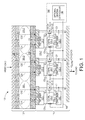
- Fig. 1 depicts a battery assembly 100 for supplying a load current C LOAD to an external load (not shown) according to a generalized embodiment of the present invention, where battery assembly 100 generally includes a battery 101 and an Adaptive Current-collector Electrochemical (ACE) system 110.
- ACE Adaptive Current-collector Electrochemical
- battery 101 is depicted in a generalized form (and not to scale) as including an anode 102, a cathode 103, an electrolyte region 105 and an upper current collection plate 106 that function to generate localized currents C11 to C32 between anode 102 and cathode 103, where each of the localized currents is generated between anode 102 and cathode 103 in an associated region of battery 101.
- Battery 101 is not limited to a particular battery type, but is preferably rechargeable (e.g., lithium-ion and sub types, e.g., Li-NMC Li-NCA, Li-FePO 4 , nickel-metal hydride or zinc-bromide).
- battery 101 is characterized by having a relatively large electrode contact area configuration (i.e., such that a width W of anode 102 and cathode 103 is substantially larger than a thickness T of battery 101, where anode 102 and cathode 103 comprise continuous (without physical segregation) structures over the entire electrode contact area).
- the large contact area configuration facilitates control over discrete battery regions 101-1, 101-2 and 101-3, which are generally depicted by dashed-line ovals.
- electrical current (depicted by two dashed-line arrows) is generated or otherwise flows between anode 102 and cathode 103 according to known battery technology.
- the localized currents in each battery region 101-1 to 101-3 are identified by two dashed-line arrows that pass through an associated dashed-line oval (e.g., localized currents C11 and C12 are generated in associated battery region 101-1, localized currents C21 and C22 are generated in associated battery region 101-2, and localized currents C31 and C32 are generated in associated battery region 101-3).
- the depiction of localized currents using two dashed-line arrows in each battery region is intended solely to indicate that current is generated in substantially all portions of each battery region.
- ACE system 110 includes spaced-apart contact pads (current collectors) 115-1, 115-2 and 115-3 that are attached to an electrode of battery 101 in a way that couples each contact pad 115-1 to 115-3 to an associated battery region 101-1 to 101-3.
- contact pads 115-1 to 115-3 are conductive (e.g., aluminum or other metal) structures that are disposed on (i.e., operably connected to) cathode 103 and arranged a spaced-apart configuration such that associated localized currents generated in battery regions 101-1 to 101-3 flow through contact pads 115-1 to 115-3, respectively.
- contact pad 115-1 is disposed on a portion of cathode 103 under discrete battery region 101-1 such that localized current portions C11 and C12 are received by (i.e., flow through) contact pad 115-1.
- contact pad 115-2 is disposed under discrete battery region 101-2 such that contact pad 115-2 receives localized current portions C21 and C22
- contact pad 115-3 is disposed under discrete battery region 101-3 such that contact pad 115-3 receives localized current portions C31 and C32.
- battery 101 is configured such that cathode 103, which typically comprises a material that is less conductive than the current collector pads, resists or prevents the flow of current between the spaced-apart contact pads (e.g., between contact pads 115-1 and 115-2, and between contact pads 115-2 and 115-3).
- cathode 103 typically comprises a material that is less conductive than the current collector pads, resists or prevents the flow of current between the spaced-apart contact pads (e.g., between contact pads 115-1 and 115-2, and between contact pads 115-2 and 115-3).
- localized battery currents generated in each battery region 101-1 to 101-3 respectively substantially entirely flow only through one associated contact pad 115-1 to 115-3.
- substantially entirely means that current portions generated in the peripheral boundary areas of the battery regions may flow to either of two adjacent contact pads, but that all current portions generated in the interior areas of each battery region flow to only one contact pad).
- contact pads 115-1 to 115-3 are depicted as being connected to cathode 103 (i.e., such that current flows from battery 101 to the load through contact pads 115-1 to 115-3), it is also possible to attached ACE system 110 to battery 101 such that contact pads 115-1 to 115-3 are connected to anode 102 (i.e., such that current flows from the load through contact pads 115-1 to 115-3 to battery 101).
- ACE system 110 includes an array of MOSFET transistors 131-1 to 131-3 that are operably connected between a current collection plate (substrate) 120 and contact pads 115-1 to 115-3, respectively.
- transistor 131-1 has a drain (first) terminal 131-11 connected to associated contact pad 115-1, a source (second) terminal 131-12 connected to collection plate 120, and a gate (control) terminal 131-13 that receives an associated control voltage V C1 .
- transistor 131-1 when transistor 131-1 is turned on by control voltage V C1 (e.g., when control voltage V C1 is above the threshold voltage of transistor 131-1), a localized current C1 (indicated by the dashed-line arrow passing through transistor 131-1) passes from contact pad 115-1 to collection plate 120, where current C1 has a current amount determined by (i.e., proportional to) the voltage level of control voltage V C1 .
- transistor 131-2 has a drain terminal 131-21 connected to contact pad 115-2, a source terminal 131-22 connected to current collection substrate 120, and a gate terminal 131-23 that receives control voltage V C2
- transistor 131-3 has a drain terminal 131-31 connected to contact pad 115-3, a source terminal 131-32 connected to current collection substrate 120, and a gate terminal 131-33 that receives control voltage V C3
- Control voltages V C1 and V C2 respectively control transistors 131-2 and 131-3 to generate localized currents C2 and C3 from contact pads 115-2 and 115-3 to collection plate 120.
- Collection plate 120 is implemented by a sheet of metal or other conductive material that facilitates the combination of localized currents C1 to C3 such that the sum of these currents form load current C LOAD .
- ACE system 110 facilitates individual control over localized battery currents generated in discrete battery regions 101-1 to 101-3 by individually adjusting the operating states of transistors 131-1 to 131-3, respectively. That is, because current portion C1 flowing through contact pad 115-1 is derived only from discrete battery region 101-1, localized control over localized currents C11 and C12 in discrete battery region 101-1 is achieved by adjusting (i.e., increasing or decreasing) control voltage V C1 , whereby the operating state of transistor 131-1 is adjusted. For example, the current flow amount associated with localized currents C11 and C12 in battery region 101-1 is effectively decreased by way of decreasing current portion C1 through transistor 131-1, which is achieved by decreasing control voltage V C1 .
- control voltage VC1 the amount of localized currents C11 and C12 in battery region 101-1 is effectively increased by increasing control voltage VC1.
- localized control over discrete battery regions 101-2 and 101-3 is achieved by way of control voltages V C2 and V C3 .
- ACE system 110 utilizes one or more components (e.g., current sensors 135-1 to 135-3 and/or temperature sensors 137-1 to 137-3) to measure localized battery operating parameters in discrete battery regions 101-1 to 101-3, and utilizes control circuitry 150 to control the operating states of transistors 131-1 to 131-3 in accordance with the measured operating parameters (i.e., to process the data associated with the measured operating parameters, and to generate control voltages V C1 , V C2 and V C3 in accordance with the processed data).
- other components e.g., voltage meters or chemical sensors may be used to measure localized battery operating parameters.
- Current sensors 135-1 to 135-3 measure the amount of current generated in discrete battery regions 101-1 to 101-3 by measuring current portions C1 to C3 passing through transistors 131-1 to 131-3 using known current measurement techniques, and generate associated current sensor signals CS C1 to CS C3 having (data) values determined by (e.g., proportional to) the measured current portions.
- current sensor 135-1 measures current portion C1 flowing between drain terminal 131-11 and source terminal 131-12 of transistor 131-1, which indicates the amount of localized current C11 and C12 generated in discrete battery region 101-1, and generates associated current sensor signal CS C1 having an analog or digital data value corresponding to measured current portion C1.
- Transmitted current sensor signals CS C2 and CS C3 include either analog or digital data values, depending on the circuitry included in current sensors 135-1 to 135-3 and the circuitry used to process the current data.
- Temperature sensors 137-1 to 137-3 are respectively disposed on contact pads 115-1 to 115-3, and measure local operating temperatures T1 to T3 in discrete battery regions 101-1 to 101-3 using known temperature measuring techniques. Temperature sensors 137-1 to 137-3 are also configured to generate associated temperature sensor signals CS T1 to CS T3 having (data) values determined by (e.g., proportional to) the measured localized temperatures T1 to T3, respectively.
- temperature sensor 137-1 is mounted on contact pad 115-1 to measure localized temperature T1 generated in discrete battery region 101-1, and generates associated temperature sensor signal CS T1 having an analog or digital data value corresponding to measured localized temperature T1.
- temperature sensors 137-2 and 137-3 measure localized temperatures T2 and T3 respectively generated in discrete battery regions 101-2 and 101-3, and generate associated temperature sensor signals CS T2 and CS T3 .
- Control circuit 150 is operably configured and fabricated using known techniques to receive and process current sensor signals CS C1 to CS C3 , temperature sensor signals CS T1 to CS T3 , or a combination of current and temperature signals, and to generate control voltages V C1 , V C2 and V C3 having voltage levels that are determined by (e.g., proportional to) at least one of the received sensor signals.
- control circuit 150 generates control voltage V C1 such that it's voltage level is proportional to sensor signals CS C1 or CS T1 , or proportional to a calculated value determined by a combination of sensor signals CS C1 or CS T1 , or proportional to a calculated value determined by two or more of current sensor signals CS C1 to CS C3 and two or more temperature sensor signals CS T1 to CS T3 .
- control circuit 150 then applies (transmits) control voltages V C1 , V C2 and V C3 onto the control terminal of transistors 131-1 to 131-3, respectively, such that localized current portions C1 to C3 passing from associated said contact pads 115-1 to 115-3 to current collection substrate 120 are determined by (e.g., made proportional to) applied control voltages V C1 , V C2 and V C3 .
- control circuit 150 is operably configured to implement a "stand-alone” control logic scheme, a “central controller” control logic scheme, or a combination of these two control logic schemes.
- control circuit 150 includes "local" control circuits 133-1 to 133-3 that are respectively disposed adjacent to discrete battery regions 101-1 to 101-3, where each control circuit 133-1 to 133-3 receives and processes operating parameter data generated for only one associated discrete battery regions 101-1 to 101-3.
- control circuit 133-1 is connected to current sensor 135-1 and is configured to compare current sensor signal CS C1 with a stored target current flow value, and to adjust (generate) control voltage V C1 in accordance with a difference between sensor signal CS C1 and the stored value.
- control circuit 133-1 is connected to receive temperature sensor signal CS T1 from temperature sensor 137-1, and is configured to adjusting control voltage V C1 in accordance with a comparison of temperature sensor signal CS T1 to a stored target temperature value.
- control circuit 133-1 is connected to receive and process both current sensor signal CS C1 and temperature sensor signal CS T1 .
- control circuit 133-2 receives and processes current sensor signal CS C2 from current sensor 135-2 and/or temperature sensor signal CS T2 from temperature sensor 137-2, and generates transistor control voltage V C2 that controls transistor 131-2
- control circuit 133-3 receives and processes current sensor signal CS C3 from current sensor 135-3 and/or temperature sensor signal CS T3 from temperature sensor 137-3, and generates transistor control voltage V C3 that controls transistor 131-3.
- each discrete battery region 101-1 to 101-3 is controlled independently from all other battery regions, where control voltages V C1 to V C3 are generated solely based on localized battery operating parameters.
- a benefit of this "stand-alone" arrangement is that this approach facilitates a cost-effective scalable battery control system that can be used for batteries of many sizes without the use of additional interconnect wiring or electronics.
- control circuit 150 includes a central controller 155 that receives the sensor signals generated by all of the sensors 135-1 to 135-3 and 137-1 to 137-3 by way of one or more bus lines 140, processes the associated data provided by the sensor signals, and transmits associated transistor control voltages V C1 to V C3 to transistors 131-1 to 133-3.
- a central controller 155 that receives the sensor signals generated by all of the sensors 135-1 to 135-3 and 137-1 to 137-3 by way of one or more bus lines 140, processes the associated data provided by the sensor signals, and transmits associated transistor control voltages V C1 to V C3 to transistors 131-1 to 133-3.
- discrete battery regions 101-1 to 101-3 are collectively controlled based on localized battery operating parameters collected from all battery regions.
- a control logic scheme is implemented in which one or more features of the "stand-alone" and “central control” control logic schemes are combined. For example, as described below with reference to Fig. 7 , a central controller is utilized to process and generate coordinated control voltage signals that are transmitted to modified "local" control circuits, which generate the transistor control voltages in response to the coordinated control voltage signals. Those skilled in the art will recognize other control logic schemes may also be utilized that fall within the spirit and scope of the present invention.
- Figs. 2(A) and 2(B) are cross-sectional views showing a partial battery assembly 100A including battery region 101-1 of battery 101 (described above) and an associated ACE system portion 110A-1 according to a first exemplary embodiment.
- ACE system portion 110A-1 includes a contact pad 115A-1 that is coupled to battery region 101-1 in the manner described above, a transistor 131A-1 that is connected between contact pad 115A-1 and a corresponding portion of current collection substrate 120A, a current sensor 135A-1 for measuring current portion (operating parameter) C1 flowing between transistor 131A-1 and current collection substrate 120A and for generating a corresponding current sensor signal CS C1 , and a "stand-alone" control circuit 150A including a local control circuit 133A-1 that receives and processes current sensor signal CS C1 , and generates corresponding control voltage V C1 that is applied on the control terminal of transistor 131A-1.
- Figs. 2(A) and 2(B) also depict current flows and signals generated in partial battery assembly 100A at two different operating time periods, where Fig. 2(A) shows battery assembly 100A at a first time t1 (designated by "100A(t1)" in the figure), and Fig. 2(B) shows battery assembly 100A at a second time t2, where time t2 occurs after time t1.
- local control circuit 133A-1 At time t1, local control circuit 133A-1 generates a control voltage V C1(t1) having a voltage level that causes transistor 131A-1 to generate a current portion C1(t1).
- current sensor 135A-1 measures current portion C1(t1) (which is the equal to the sum of localized currents C11 and C12 in battery region 101-1 at time t1), and transmits a corresponding sensor signal CS C1(t1) to local control circuit 133A-1.
- local control circuit 133A-1 compares sensor signal CS C1(t1) with one or more stored target current flow values CT in order to determine if battery region 101-1 is within a preset target current range, and adjusts (i.e., increases or decreases) control voltage V C1 in accordance with this comparison.
- current portion C1(t1) is deemed lower than the target current range, which is indicated in Fig. 2(A) as "C1(t1) ⁇ CT" and indicates that localized currents C11 and C12 are too low.
- local control circuit 133A-1 reacts by increasing control voltage V C1 in order to increase the flow through transistor 131A-1, which in turn causes localized currents C1 and C2 to increase.
- local control circuit 133A-1 generates adjusted control voltage V C1(t2) having a voltage level that is higher than control voltage V C1(t1) by a predetermined amount, thereby causing transistor 131A-1 to generate a current portion C1(t2) that is higher than current portion C1(t1).
- Current sensor 135A-1 measures current portion C1(t2) (which is the equal to the sum of localized currents C11 and C12 in battery region 101-1 at time t2), and transmits a corresponding sensor signal CS C1(t2) to local control circuit 133A-1, whereby further adjustment (if necessary) is made by repeating the process described above with reference to Fig. 2(A) .
- Figs. 3(A) and 3(B) are cross-sectional views showing a partial battery assembly 100B including battery region 101-1 of battery 101 and an associated ACE system portion 110B-1 according to a second exemplary embodiment that uses the "central controller" control logic scheme.
- ACE system portion 110B-1 includes a transistor 131B-1 connected between contact pad 115B-1 and current collection substrate 120B, and a current sensor 135B-1 for measuring current portion C1.
- control circuit 150B includes a central control (CC) circuit 155B that receives current sensor signals from multiple current sensors (including current sensor signal CS C1 received from current sensor 135B-1) by way of bus line (or dedicated signal lines) 140, and generates corresponding control voltages that are applied on the control terminal of associated transistors (e.g., control voltage V C1 is transmitted to the gate terminal of transistor 131B-1).
- CC central control
- local control circuit 133A-1 At time t3, local control circuit 133A-1 generates a control voltage V C1(t3) that generates a current portion C1(t1) from battery region 101-1 through transistor 131A-1, which is measured by current sensor 135A-1, which passes corresponding sensor signal CS C1(t3) to central controller 155B by way of line 140.
- Central controller 155B receives sensor signal CS C1(t3) and sensor signals from other current sensors, processes the sensor signals in accordance with stored logic (e.g., adjusts control voltage V C1 based on received first sensor signal CS C1(t3) ).
- current portion C1(t3) is deemed higher than the target current range, which is indicated in Fig.
- central controller 155B reacts by decreasing the control voltage for transistor 131B-1 in order to decrease the flow through transistor 131B-1, which in turn causes localized currents C1 and C2 to increase.
- Fig. 3(B) which shows battery assembly 100A at time t4
- local control circuit 133B-1 generates adjusted control voltage V C1(t4) having a voltage level that is lower than control voltage V C1(t3) by a predetermined amount, thereby causing transistor 131B-1 to generate a current portion C1(t4) that is lower than current portion C1(t3).
- Figs. 4(A) and 4(B) illustrate an example in which an over-temperature condition is caused by a minor local fault, the adaptive current collector adjusts current flow to reduce localized temperature.
- ACE system 100C-1 includes a transistor 131C-1 connected between contact pad 115C-1 and substrate 120C, a temperature sensor 137C-1 for measuring a localized operating temperature (operating parameter) T1 of battery 101 in battery region 101-1, and for generating a corresponding temperature sensor signal CS T1 , and a "stand-alone" control circuit 150C including a local control circuit 133C-1 that receives and processes temperature sensor signal CS T1 , and generates corresponding control voltage V C1 that is applied on the control terminal of transistor 131C-1.
- local control circuit 133C-1 At time t5, local control circuit 133C-1 generates a control voltage V C1(t5) that produces current portion C1(t5), and temperature sensor 137C-1 measures temperature T 101-1(t5) , and transmits a corresponding sensor signal CS T1(t5) to local control circuit 133C-1, which compares sensor signal CS T1(t5) with one or more stored target temperature values (e.g., a maximum optimal operating temperature T MAX ), and adjusts (i.e., increases or decreases) control voltage V C1 in accordance with this comparison.
- target temperature values e.g., a maximum optimal operating temperature T MAX
- Figs. 5(A) and 5(B) illustrate another example in which an over-temperature condition is caused by major adverse condition (e.g., a fire) or major fault that cascades across the cell and represents a safety risk, where the adaptive current collector reacts across all control areas to shutdown the battery.
- major adverse condition e.g., a fire
- major fault that cascades across the cell and represents a safety risk
- ACE system portion 110D-1 includes a transistor 131D-1 connected between contact pad 115D-1 and current collection substrate 120D, a temperature sensor 137D-1 disposed to measure localized temperature T 101-1 in region 101-1 of battery 101, where control circuit 150D includes a central control (CC) circuit 155D that receives sensor signals from multiple sensors (including sensor signal CS T1 from temperature sensor 137D-1) by way of lines 140, and generates corresponding control voltages that are transmitted over lines 140 to associated transistors (e.g., signal V C1 is transmitted to transistor 131D-1).
- CC central control
- the adaptive current collector arrangements utilizing "stand-alone" control circuits enable localized control over each battery region when localized currents are lower than or exceed the design threshold (target value), regardless of the cause. If battery 101 has local defects that diminish output by generating an under-current, one or more local control circuits automatically adapt (adjust) their associated control voltage upward (e.g., in the manner control circuit 133A-1 adjusts control voltage V C1 upward as described above with reference to Figs. 2(A) and 2(B) ), thereby reducing transistor resistance (i.e., increases transistor conductance) in the defective battery region(s) to promote current generation.
- the adaptive current collector arrangement automatically decreases conductivity (increases resistance) to maintain current within the control band, as described with reference to Figs. 4(A) and 4(B) .
- the local control circuits automatically adapt by turning off the transistors to terminate current generation inside battery 101 in a manner similar to that described with reference to Fig. 5(B) , whereby the release of energy from battery 101 is unable to exceed the design limit by physical isolation of the active battery material, directly mitigating all downstream risks.
- the closed-loop adaptive control operations performed by control circuit 150A are implemented during both charge and discharge cycles.
- the adaptive current collector arrangements utilizing "central controller" control circuits enable coordinated control over all battery regions to facilitate adjusting localized currents to adjust for current/temperature conditions that are lower than or exceed the design threshold (target value), regardless of the cause.
- target value design threshold
- ACE systems of the present invention facilitate the production of self-sufficient battery assemblies that eliminate the need for most overhead systems.
- Figs. 6(A) and 6(B) are exploded perspective views showing a battery assembly 100E according to a practical embodiment in which ACE system 110E is constructed using thin film electronics.
- Battery 101 includes anode 102, cathode 103, electrolyte region 105, and anode current collector plate 106.
- ACE system 110E includes an array of "stand-alone" control/sensor units 160E disposed on a flexible thin film (e.g., plastic) substrate 111E, an array of array of spaced-apart contact pads 115E disposed over substrate 111E, and a collection plate 120E disposed under substrate 111E.
- a flexible thin film e.g., plastic
- Each control/sensor unit 160E is connected by conductive traces to an associated thin film transistor, which is connected between an associated contact pad 115E and collection plate 120.
- control/sensor unit 160-18 is connected by conductive traces to associated bipolar-type thin film transistor 131E-18, which has an emitter terminal connected by a first metal via structure to contact pad 115E-18, a collector terminal connected by a second metal via structure extending through an insulating layer 112E to current collection substrate 120E, and a control (base) terminal connected to receive a control voltage from control/sensor unit 160E-18.
- Control/sensor unit 160-18 is an integrated circuit including both circuitry for measuring the current passing through transistor 131E-18, and processing circuitry for generating the control voltage applied to the bases terminal of transistor 131E-18 using a "stand-alone" control logic scheme similar to that described above, whereby control/sensor unit 160E-18 controls the localized current portion flowing from contact pad 115E-18 to current collection substrate 120E.
- control/sensor unit 160E-18 controls discrete battery region 101-18 of battery 101, and the remaining control/sensor units 160E individually control discrete battery regions 101-11 to 101-98 of battery 101.
- ACE system 110E is made approximately the same thickness as a conventional aluminum foil, and serves as a substrate for cathode coating to integrate into conventional manufacturing processes.
- Fig. 7 is a simplified block diagram showing an ACE system 110F according to another exemplary embodiment. Similar to the previous embodiment, ACE system 110F is fabricated on a flexible thin film (e.g., plastic) substrate 111F and includes an array of control/sensor (CNT/SEN) units 160F-11 to 160F-mn and associated thin film transistors that are connected to corresponding contact pads 115F-11 to 115F-mn using the techniques described above. ACE system 110F differs from the previous embodiment in that it also includes a central controller 155F configured to communicate with control/sensor units 160F-11 to 160F-mn by way of bus lines 140F-1 to 140F-n.
- CNT/SEN control/sensor
- Central controller 155F implements control logic that combines features of the "stand-alone” and “central controller” logic schemes described above in that each control/sensor units 160F-11 to 160F-mn controls an associated region of a battery (not shown) using the "stand-alone” logic scheme, but also transmits alarm signals (e.g., sensor or other signals) to central controller 155F by way of bus lines 140F-1 to 140F-n.
- alarm signals e.g., sensor or other signals
- each control/sensor units 160F-11 to 160F-mn sets the conductance of its associated transistor based on stored target specification values (e.g., a target current flow value) transmitted from central controller 155F, and utilizes its own "local" sensor measurements to adjust the localized current flow as needed. If the battery region controlled by a particular control/sensor unit exceeds a stored alarm limit (e.g., the current or temperature are too high), then control/sensor units 160F-11 to 160F-mn are configured to shut down the failed battery region and to send an appropriate signal to central controller 155F.
- stored target specification values e.g., a target current flow value
- Central controller 155F is then able to permanently shut down battery regions adjacent to the damaged battery region and make adjustments to the specifications sent to other control/sensor units, thereby providing parallel sensing and control redundancy and robustness with graceful degradation characteristics, acting as a failsafe that provides open circuit isolation of the active material in damaged battery regions.
- Figs. 8-10 illustrate operation of a battery assembly 100F that includes a battery 101 similar to that described above with reference to Fig. 6(A) , and using ACE system 110F, which is described above with reference to Fig. 7 .
- battery 101 includes sixty-four discrete battery regions (indicated by dashed lines) that are accessed by ACE system 110F using the methods described above.
- battery assembly 100F is shown after a discrete battery region 101-36 has failed, which is detected by the associated local control/sensor unit (e.g., by way of measured out-of-range current or temperature).
- the associated control/sensor unit terminates current generation in failed battery region 101-36 (e.g., by applying a "0V" control signal to the transistor controlling battery region 101-36, which is indicated by dark shading), and transmits a control signal to central controller 155F (shown in Fig. 7 ). Subsequently, as indicated in Fig. 9 , central controller 155F transmits specifications to adjacent control/sensor units that reduces current flow in selected battery regions surrounding failed region 101-36 (e.g., battery regions 101-25 and 101-27, indicated by light shading) in order to minimize possible catastrophic failure. In one practical example, these safety actions including decreasing power output from these surrounding battery regions by 20%, resulting in 4% reduction of power generated by battery 101.
- FIG. 10 illustrates battery assembly 100F after central controller 155F implements a compensation scheme in which additional control signals are transmitted to the control/sensor units controlling peripheral battery regions (e.g., battery regions 101-11, 101-88 and the intervening battery regions indicated by the L-shape shaded area in Fig. 10 ), whereby current generation is increased in each of these battery regions by 17%, whereby the total battery output power level of battery 101 is restored to full power.
- peripheral battery regions e.g., battery regions 101-11, 101-88 and the intervening battery regions indicated by the L-shape shaded area in Fig. 10
- ACE system of the present invention will necessarily add marginal cost and decrease volumetric energy density at the cell level, its dramatic impact on the balance of an EV battery system has the potential to offset this cost several times over. Additional cost advantages are possible through reduced battery material purity and fabrication control requirements because the ACE system provides an ability to compensate for minor manufacturing defects. Ongoing EV battery system analysis indicates the potential to achieve an approximately 25% reduction in weight and cost using the system of the present invention.
Landscapes
- Engineering & Computer Science (AREA)
- Manufacturing & Machinery (AREA)
- Chemical & Material Sciences (AREA)
- Chemical Kinetics & Catalysis (AREA)
- Electrochemistry (AREA)
- General Chemical & Material Sciences (AREA)
- Microelectronics & Electronic Packaging (AREA)
- Automation & Control Theory (AREA)
- Secondary Cells (AREA)
- Battery Mounting, Suspending (AREA)
- Charge And Discharge Circuits For Batteries Or The Like (AREA)
Abstract
Description
- This invention relates to batteries, and in particular to battery control systems.
- A battery requires the concentration of energy in order to serve its purpose, and the uncontrolled release of concentrated energy poses an inherent safety risk. In electric vehicles (EVs), for example, the battery system design is driven by the spiraling mitigation of this risk - from lower energy battery chemistry selection, to embedded cell safety elements, to reduced packing density, to battery management system (BMS) monitoring and safety circuits, to vehicle structural protection. These mitigation layers have been only partially successful in preventing catastrophic battery events, and come at the price of increased cost and weight that directly limit EV commercial viability. While more efficient mitigation approaches may be possible, in order to break out of this spiral and achieve the full potential of EVs, battery cells must be made to be self-sufficient with intrinsic mitigation of their inherent risks.
- The present invention is directed to a battery assembly including a battery and an Adaptive Current-collector Electrochemical (ACE) system that controls battery operation (i.e., current flow between the battery and a load circuit) by controlling the generation of localized current flow in discrete regions of the battery.
- According to a first aspect of the present invention, the ACE system utilizes spaced-apart contact pads that are attached to one of the battery's electrodes (i.e., either the anode or the cathode) in a way that couples each contact pad to an associated battery region (i.e., such that substantially all of the localized battery current generated in a particular discrete battery region flows through one associated contact pad). By providing the spaced-apart contact pads in this manner, the present invention facilitates individual control over localized current flows in each battery region.
- According to a second aspect of the present invention, the ACE system includes an array of transistors and associated control circuitry that individually control current flows between the contact pads and a current collection plate (substrate). Each transistor has a first (e.g., drain or emitter) terminal connected to an associated contact pad, a second (e.g., source or collector) terminal connected to the current collection substrate, and a control (e.g., gate or base) terminal that receives an associated control voltage transmitted from the control circuit. By adjusting (i.e., increasing or decreasing) the control voltage applied to each transistor, the ACE system controls the localized current portion flowing from each contact pad to the current collection substrate. Because the current flowing through each contact pad is derived from only one discrete battery region, this arrangement facilitates localized control over battery operations. Specifically, the amount of localized battery current generated a particular discrete battery region is increased, decreased or turned off by controlling the operating state of the transistor coupled to that particular discrete battery region by way of an associated contact pad. The present invention thus provides self-sufficient battery management that both optimizes battery operation and prevents a local failure in one battery region from producing a catastrophic total battery failure by allowing the local failed battery region to be turned off.
- According to a third aspect of the present invention, the ACE system utilizes an array of sensors to measure one or more localized battery operating parameters in each of the discrete battery regions, and the control circuitry processes the sensor data and controls the transistors in accordance with the measured operating parameters such that battery operations are optimized. In one embodiment, both a current sensor and a temperature sensor are utilized to measure localized operating parameters in each of the discrete battery regions (e.g., an amount of current passing through a particular discrete battery region, and the temperature of the particular discrete battery region), and to generate associated sensor signals having values determined in accordance with these measured localized operating parameters. In a "stand-alone" control circuit embodiment, multiple "local" control circuits are utilized such that each control circuit receives sensor signals generated for only one associated discrete battery region, compares the sensor signals with stored target values, and generates an associated transistor control voltage that controls an associated current control transistor. A benefit of this "stand-alone"control logic scheme is that this approach facilitates a cost-effective scalable battery control system that can be used for batteries of many sizes without the use of additional interconnect wiring or electronics. In a "central control" embodiment, a central controller receives and processes data from all of the sensors, and transmits associated transistor control voltages to each current control transistors. Although the "central controller" embodiment requires additional overhead (e.g., bus lines) that limit scalability, this approach facilitates coordinated battery control strategies that cannot be achieved using the stand-alone approach, such as increasing current generation in healthy battery regions while decreasing current generation in failed or problematic battery regions to maintain optimal battery output.
- These and other features, aspects and advantages of the present invention will become better understood with regard to the following description, appended claims, and accompanying drawings, where:
-
Fig. 1 is a simplified diagram showing a battery assembly including an ACE system according to an embodiment of the present invention; -
Figs. 2(A) and 2(B) are partial views showing a battery assembly including an ACE system according to another embodiment of the present invention; -
Figs. 3(A) and 3(B) are partial views showing a battery assembly including an ACE system according to another embodiment of the present invention; -
Figs. 4(A) and 4(B) are partial views showing a battery assembly including an ACE system according to another embodiment of the present invention; -
Figs. 5(A) and 5(B) are partial views showing a battery assembly including an ACE system according to another embodiment of the present invention; -
Fig. 6(A) is an exploded perspective view showing a battery assembly including an ACE system according to another embodiment of the present invention; -
Fig. 6(B) is an enlarged partial exploded perspective view showing a portion of the ACE system ofFig. 6 (A) ; -
Fig. 7 is a simplified block diagram showing an ACE system according to another embodiment of the present invention; -
Fig. 8 is a perspective view showing a battery assembly including the ACE system ofFig. 7 during a first operating period; -
Fig. 9 is a perspective view showing a battery assembly including the ACE system ofFig. 7 during a second operating period; and -
Fig. 10 is a perspective view showing a battery assembly including the ACE system ofFig. 7 during a third operating period. - The present invention relates to an improvement in battery control systems. The following description is presented to enable one of ordinary skill in the art to make and use the invention as provided in the context of a particular application and its requirements. As used herein, directional terms such as "upper", and "over" are intended to provide relative positions for purposes of description, and are not intended to designate an absolute frame of reference. The terms "coupled" and "connected", which are utilized herein, are defined as follows. The term "connected" is used to describe a direct connection between two circuit elements, for example, by way of a metal line formed in accordance with normal integrated circuit fabrication techniques. In contrast, the term "coupled" is used to describe either a direct connection or an indirect connection between two circuit elements. For example, two coupled elements may be directly connected by way of a metal line, or indirectly connected by way of an intervening circuit element (e.g., a capacitor, resistor, inductor, or by way of the source/drain terminals of a transistor) or by inductance. Various modifications to the preferred embodiment will be apparent to those with skill in the art, and the general principles defined herein may be applied to other embodiments. Therefore, the present invention is not intended to be limited to the particular embodiments shown and described, but is to be accorded the widest scope consistent with the principles and novel features herein disclosed.
-
Fig. 1 depicts abattery assembly 100 for supplying a load current CLOAD to an external load (not shown) according to a generalized embodiment of the present invention, wherebattery assembly 100 generally includes abattery 101 and an Adaptive Current-collector Electrochemical (ACE)system 110. - Referring to the upper portion of
Fig. 1 ,battery 101 is depicted in a generalized form (and not to scale) as including ananode 102, acathode 103, anelectrolyte region 105 and an uppercurrent collection plate 106 that function to generate localized currents C11 to C32 betweenanode 102 andcathode 103, where each of the localized currents is generated betweenanode 102 andcathode 103 in an associated region ofbattery 101.Battery 101 is not limited to a particular battery type, but is preferably rechargeable (e.g., lithium-ion and sub types, e.g., Li-NMC Li-NCA, Li-FePO4, nickel-metal hydride or zinc-bromide). In addition,battery 101 is characterized by having a relatively large electrode contact area configuration (i.e., such that a width W ofanode 102 andcathode 103 is substantially larger than a thickness T ofbattery 101, whereanode 102 andcathode 103 comprise continuous (without physical segregation) structures over the entire electrode contact area). As explained below, the large contact area configuration facilitates control over discrete battery regions 101-1, 101-2 and 101-3, which are generally depicted by dashed-line ovals. During operation, electrical current (depicted by two dashed-line arrows) is generated or otherwise flows betweenanode 102 andcathode 103 according to known battery technology. For descriptive purposes, the localized currents in each battery region 101-1 to 101-3 are identified by two dashed-line arrows that pass through an associated dashed-line oval (e.g., localized currents C11 and C12 are generated in associated battery region 101-1, localized currents C21 and C22 are generated in associated battery region 101-2, and localized currents C31 and C32 are generated in associated battery region 101-3). The depiction of localized currents using two dashed-line arrows in each battery region is intended solely to indicate that current is generated in substantially all portions of each battery region. - According to a first aspect of the present invention,
ACE system 110 includes spaced-apart contact pads (current collectors) 115-1, 115-2 and 115-3 that are attached to an electrode ofbattery 101 in a way that couples each contact pad 115-1 to 115-3 to an associated battery region 101-1 to 101-3. In the embodiment shown inFig. 1 , contact pads 115-1 to 115-3 are conductive (e.g., aluminum or other metal) structures that are disposed on (i.e., operably connected to)cathode 103 and arranged a spaced-apart configuration such that associated localized currents generated in battery regions 101-1 to 101-3 flow through contact pads 115-1 to 115-3, respectively. Specifically, contact pad 115-1 is disposed on a portion ofcathode 103 under discrete battery region 101-1 such that localized current portions C11 and C12 are received by (i.e., flow through) contact pad 115-1. Similarly, contact pad 115-2 is disposed under discrete battery region 101-2 such that contact pad 115-2 receives localized current portions C21 and C22, and contact pad 115-3 is disposed under discrete battery region 101-3 such that contact pad 115-3 receives localized current portions C31 and C32. Note thatbattery 101 is configured such thatcathode 103, which typically comprises a material that is less conductive than the current collector pads, resists or prevents the flow of current between the spaced-apart contact pads (e.g., between contact pads 115-1 and 115-2, and between contact pads 115-2 and 115-3). As such, localized battery currents generated in each battery region 101-1 to 101-3 respectively substantially entirely flow only through one associated contact pad 115-1 to 115-3. As used herein, "substantially entirely" means that current portions generated in the peripheral boundary areas of the battery regions may flow to either of two adjacent contact pads, but that all current portions generated in the interior areas of each battery region flow to only one contact pad). Note also that, although contact pads 115-1 to 115-3 are depicted as being connected to cathode 103 (i.e., such that current flows frombattery 101 to the load through contact pads 115-1 to 115-3), it is also possible to attachedACE system 110 tobattery 101 such that contact pads 115-1 to 115-3 are connected to anode 102 (i.e., such that current flows from the load through contact pads 115-1 to 115-3 to battery 101). - According to another aspect of the present invention,
ACE system 110 includes an array of MOSFET transistors 131-1 to 131-3 that are operably connected between a current collection plate (substrate) 120 and contact pads 115-1 to 115-3, respectively. Specifically, transistor 131-1 has a drain (first) terminal 131-11 connected to associated contact pad 115-1, a source (second) terminal 131-12 connected tocollection plate 120, and a gate (control) terminal 131-13 that receives an associated control voltage VC1. With this arrangement, when transistor 131-1 is turned on by control voltage VC1 (e.g., when control voltage VC1 is above the threshold voltage of transistor 131-1), a localized current C1 (indicated by the dashed-line arrow passing through transistor 131-1) passes from contact pad 115-1 tocollection plate 120, where current C1 has a current amount determined by (i.e., proportional to) the voltage level of control voltage VC1. Similarly, transistor 131-2 has a drain terminal 131-21 connected to contact pad 115-2, a source terminal 131-22 connected tocurrent collection substrate 120, and a gate terminal 131-23 that receives control voltage VC2, and transistor 131-3 has a drain terminal 131-31 connected to contact pad 115-3, a source terminal 131-32 connected tocurrent collection substrate 120, and a gate terminal 131-33 that receives control voltage VC3. Control voltages VC1 and VC2 respectively control transistors 131-2 and 131-3 to generate localized currents C2 and C3 from contact pads 115-2 and 115-3 tocollection plate 120.Collection plate 120 is implemented by a sheet of metal or other conductive material that facilitates the combination of localized currents C1 to C3 such that the sum of these currents form load current CLOAD. -
ACE system 110 facilitates individual control over localized battery currents generated in discrete battery regions 101-1 to 101-3 by individually adjusting the operating states of transistors 131-1 to 131-3, respectively. That is, because current portion C1 flowing through contact pad 115-1 is derived only from discrete battery region 101-1, localized control over localized currents C11 and C12 in discrete battery region 101-1 is achieved by adjusting (i.e., increasing or decreasing) control voltage VC1, whereby the operating state of transistor 131-1 is adjusted. For example, the current flow amount associated with localized currents C11 and C12 in battery region 101-1 is effectively decreased by way of decreasing current portion C1 through transistor 131-1, which is achieved by decreasing control voltage VC1. Conversely, the amount of localized currents C11 and C12 in battery region 101-1 is effectively increased by increasing control voltage VC1. In a similar manner, localized control over discrete battery regions 101-2 and 101-3 is achieved by way of control voltages VC2 and VC3. - According to a third aspect of the present invention,
ACE system 110 utilizes one or more components (e.g., current sensors 135-1 to 135-3 and/or temperature sensors 137-1 to 137-3) to measure localized battery operating parameters in discrete battery regions 101-1 to 101-3, and utilizescontrol circuitry 150 to control the operating states of transistors 131-1 to 131-3 in accordance with the measured operating parameters (i.e., to process the data associated with the measured operating parameters, and to generate control voltages VC1, VC2 and VC3 in accordance with the processed data). In addition to current and temperature sensors, other components (e.g., voltage meters or chemical sensors) may be used to measure localized battery operating parameters. - Current sensors 135-1 to 135-3 measure the amount of current generated in discrete battery regions 101-1 to 101-3 by measuring current portions C1 to C3 passing through transistors 131-1 to 131-3 using known current measurement techniques, and generate associated current sensor signals CSC1 to CSC3 having (data) values determined by (e.g., proportional to) the measured current portions.
Specifically, current sensor 135-1 measures current portion C1 flowing between drain terminal 131-11 and source terminal 131-12 of transistor 131-1, which indicates the amount of localized current C11 and C12 generated in discrete battery region 101-1, and generates associated current sensor signal CSC1 having an analog or digital data value corresponding to measured current portion C1. Similarly, current sensors 135-2 and 135-3 measure current portions C2 and C3 respectively flowing through transistors 131-2 and 131-3, and generate associated current sensor signals CSC2 and CSC3. Transmitted current sensor signals CSC2 and CSC3 include either analog or digital data values, depending on the circuitry included in current sensors 135-1 to 135-3 and the circuitry used to process the current data. - Temperature sensors 137-1 to 137-3 are respectively disposed on contact pads 115-1 to 115-3, and measure local operating temperatures T1 to T3 in discrete battery regions 101-1 to 101-3 using known temperature measuring techniques. Temperature sensors 137-1 to 137-3 are also configured to generate associated temperature sensor signals CST1 to CST3 having (data) values determined by (e.g., proportional to) the measured localized temperatures T1 to T3, respectively. Specifically, temperature sensor 137-1 is mounted on contact pad 115-1 to measure localized temperature T1 generated in discrete battery region 101-1, and generates associated temperature sensor signal CST1 having an analog or digital data value corresponding to measured localized temperature T1. Similarly, temperature sensors 137-2 and 137-3 measure localized temperatures T2 and T3 respectively generated in discrete battery regions 101-2 and 101-3, and generate associated temperature sensor signals CST2 and CST3.
-
Control circuit 150 is operably configured and fabricated using known techniques to receive and process current sensor signals CSC1 to CSC3, temperature sensor signals CST1 to CST3, or a combination of current and temperature signals, and to generate control voltages VC1, VC2 and VC3 having voltage levels that are determined by (e.g., proportional to) at least one of the received sensor signals. For example,control circuit 150 generates control voltage VC1 such that it's voltage level is proportional to sensor signals CSC1 or CST1, or proportional to a calculated value determined by a combination of sensor signals CSC1 or CST1, or proportional to a calculated value determined by two or more of current sensor signals CSC1 to CSC3 and two or more temperature sensor signals CST1 to CST3. As mentioned above,control circuit 150 then applies (transmits) control voltages VC1, VC2 and VC3 onto the control terminal of transistors 131-1 to 131-3, respectively, such that localized current portions C1 to C3 passing from associated said contact pads 115-1 to 115-3 tocurrent collection substrate 120 are determined by (e.g., made proportional to) applied control voltages VC1, VC2 and VC3. - According to alternative specific embodiments of the present invention,
control circuit 150 is operably configured to implement a "stand-alone" control logic scheme, a "central controller" control logic scheme, or a combination of these two control logic schemes. - Under the "stand-alone" control logic approach,
control circuit 150 includes "local" control circuits 133-1 to 133-3 that are respectively disposed adjacent to discrete battery regions 101-1 to 101-3, where each control circuit 133-1 to 133-3 receives and processes operating parameter data generated for only one associated discrete battery regions 101-1 to 101-3. For example, control circuit 133-1 is connected to current sensor 135-1 and is configured to compare current sensor signal CSC1 with a stored target current flow value, and to adjust (generate) control voltage VC1 in accordance with a difference between sensor signal CSC1 and the stored value. Alternatively, control circuit 133-1 is connected to receive temperature sensor signal CST1 from temperature sensor 137-1, and is configured to adjusting control voltage VC1 in accordance with a comparison of temperature sensor signal CST1 to a stored target temperature value. In yet another alternative embodiment, control circuit 133-1 is connected to receive and process both current sensor signal CSC1 and temperature sensor signal CST1. At the same time, control circuit 133-2 receives and processes current sensor signal CSC2 from current sensor 135-2 and/or temperature sensor signal CST2 from temperature sensor 137-2, and generates transistor control voltage VC2 that controls transistor 131-2, and control circuit 133-3 receives and processes current sensor signal CSC3 from current sensor 135-3 and/or temperature sensor signal CST3 from temperature sensor 137-3, and generates transistor control voltage VC3 that controls transistor 131-3. As described in additional below with reference to the examples described with reference toFigs. 2(A), 2(B) ,4(A) and 4(B) , each discrete battery region 101-1 to 101-3 is controlled independently from all other battery regions, where control voltages VC1 to VC3 are generated solely based on localized battery operating parameters. A benefit of this "stand-alone" arrangement is that this approach facilitates a cost-effective scalable battery control system that can be used for batteries of many sizes without the use of additional interconnect wiring or electronics. - Under the "central control" control logic approach,
control circuit 150 includes acentral controller 155 that receives the sensor signals generated by all of the sensors 135-1 to 135-3 and 137-1 to 137-3 by way of one ormore bus lines 140, processes the associated data provided by the sensor signals, and transmits associated transistor control voltages VC1 to VC3 to transistors 131-1 to 133-3. As described in additional below with reference to the examples described with reference toFigs. 3(A), 3(B) ,5(A) and 5(B) , discrete battery regions 101-1 to 101-3 are collectively controlled based on localized battery operating parameters collected from all battery regions. Although this "central controller" control logic approach requires additional overhead in the form ofbus lines 140 that increase manufacturing costs and may limit scalability (e.g., a separately manufactured ACE system may be required for different battery sizes), this approach facilitates coordinated battery control schemes (described below) that cannot be achieved using the "stand-alone" approach. - In other embodiments, a control logic scheme is implemented in which one or more features of the "stand-alone" and "central control" control logic schemes are combined. For example, as described below with reference to
Fig. 7 , a central controller is utilized to process and generate coordinated control voltage signals that are transmitted to modified "local" control circuits, which generate the transistor control voltages in response to the coordinated control voltage signals. Those skilled in the art will recognize other control logic schemes may also be utilized that fall within the spirit and scope of the present invention. -
Figs. 2(A) and 2(B) are cross-sectional views showing apartial battery assembly 100A including battery region 101-1 of battery 101 (described above) and an associatedACE system portion 110A-1 according to a first exemplary embodiment. In particular,ACE system portion 110A-1 includes acontact pad 115A-1 that is coupled to battery region 101-1 in the manner described above, atransistor 131A-1 that is connected betweencontact pad 115A-1 and a corresponding portion ofcurrent collection substrate 120A, acurrent sensor 135A-1 for measuring current portion (operating parameter) C1 flowing betweentransistor 131A-1 andcurrent collection substrate 120A and for generating a corresponding current sensor signal CSC1, and a "stand-alone"control circuit 150A including alocal control circuit 133A-1 that receives and processes current sensor signal CSC1, and generates corresponding control voltage VC1 that is applied on the control terminal oftransistor 131A-1.Figs. 2(A) and 2(B) also depict current flows and signals generated inpartial battery assembly 100A at two different operating time periods, whereFig. 2(A) showsbattery assembly 100A at a first time t1 (designated by "100A(t1)" in the figure), andFig. 2(B) showsbattery assembly 100A at a second time t2, where time t2 occurs after time t1. - Referring to
Fig. 2(A) , at time t1,local control circuit 133A-1 generates a control voltage VC1(t1) having a voltage level that causestransistor 131A-1 to generate a current portion C1(t1). At the same time,current sensor 135A-1 measures current portion C1(t1) (which is the equal to the sum of localized currents C11 and C12 in battery region 101-1 at time t1), and transmits a corresponding sensor signal CSC1(t1) tolocal control circuit 133A-1. Using the "stand-alone" control logic scheme,local control circuit 133A-1 compares sensor signal CSC1(t1) with one or more stored target current flow values CT in order to determine if battery region 101-1 is within a preset target current range, and adjusts (i.e., increases or decreases) control voltage VC1 in accordance with this comparison. For purposes of explanation, current portion C1(t1) is deemed lower than the target current range, which is indicated inFig. 2(A) as "C1(t1)<CT" and indicates that localized currents C11 and C12 are too low. As such,local control circuit 133A-1 reacts by increasing control voltage VC1 in order to increase the flow throughtransistor 131A-1, which in turn causes localized currents C1 and C2 to increase. - Referring to
Fig. 2(B) , which showsbattery assembly 100A at time t2 subsequent to time t1,local control circuit 133A-1 generates adjusted control voltage VC1(t2) having a voltage level that is higher than control voltage VC1(t1) by a predetermined amount, thereby causingtransistor 131A-1 to generate a current portion C1(t2) that is higher than current portion C1(t1).Current sensor 135A-1 measures current portion C1(t2) (which is the equal to the sum of localized currents C11 and C12 in battery region 101-1 at time t2), and transmits a corresponding sensor signal CSC1(t2) tolocal control circuit 133A-1, whereby further adjustment (if necessary) is made by repeating the process described above with reference toFig. 2(A) . -
Figs. 3(A) and 3(B) are cross-sectional views showing apartial battery assembly 100B including battery region 101-1 ofbattery 101 and an associatedACE system portion 110B-1 according to a second exemplary embodiment that uses the "central controller" control logic scheme. Similar to the previous embodiment,ACE system portion 110B-1 includes atransistor 131B-1 connected betweencontact pad 115B-1 andcurrent collection substrate 120B, and acurrent sensor 135B-1 for measuring current portion C1.ACE system portion 110B-1 differs from the previous embodiment in thatcontrol circuit 150B includes a central control (CC)circuit 155B that receives current sensor signals from multiple current sensors (including current sensor signal CSC1 received fromcurrent sensor 135B-1) by way of bus line (or dedicated signal lines) 140, and generates corresponding control voltages that are applied on the control terminal of associated transistors (e.g., control voltage VC1 is transmitted to the gate terminal oftransistor 131B-1). Referring toFig. 3(A) , at time t3,local control circuit 133A-1 generates a control voltage VC1(t3) that generates a current portion C1(t1) from battery region 101-1 throughtransistor 131A-1, which is measured bycurrent sensor 135A-1, which passes corresponding sensor signal CSC1(t3) tocentral controller 155B by way ofline 140.Central controller 155B receives sensor signal CSC1(t3) and sensor signals from other current sensors, processes the sensor signals in accordance with stored logic (e.g., adjusts control voltage VC1 based on received first sensor signal CSC1(t3)). For purposes of explanation, current portion C1(t3) is deemed higher than the target current range, which is indicated inFig. 3(A) as "C1(t3)>CT" and indicates that the localized currents in battery region 101-1 are too high. As such,central controller 155B reacts by decreasing the control voltage fortransistor 131B-1 in order to decrease the flow throughtransistor 131B-1, which in turn causes localized currents C1 and C2 to increase. Referring toFig. 3(B) , which showsbattery assembly 100A at time t4, local control circuit 133B-1 generates adjusted control voltage VC1(t4) having a voltage level that is lower than control voltage VC1(t3) by a predetermined amount, thereby causingtransistor 131B-1 to generate a current portion C1(t4) that is lower than current portion C1(t3). -
Figs. 4(A) and 4(B) illustrate an example in which an over-temperature condition is caused by a minor local fault, the adaptive current collector adjusts current flow to reduce localized temperature. In thisembodiment ACE system 100C-1 includes a transistor 131C-1 connected between contact pad 115C-1 andsubstrate 120C, atemperature sensor 137C-1 for measuring a localized operating temperature (operating parameter) T1 ofbattery 101 in battery region 101-1, and for generating a corresponding temperature sensor signal CST1, and a "stand-alone"control circuit 150C including alocal control circuit 133C-1 that receives and processes temperature sensor signal CST1, and generates corresponding control voltage VC1 that is applied on the control terminal of transistor 131C-1. Referring toFig. 4(A) , at time t5,local control circuit 133C-1 generates a control voltage VC1(t5) that produces current portion C1(t5), andtemperature sensor 137C-1 measures temperature T101-1(t5), and transmits a corresponding sensor signal CST1(t5) tolocal control circuit 133C-1, which compares sensor signal CST1(t5) with one or more stored target temperature values (e.g., a maximum optimal operating temperature TMAX), and adjusts (i.e., increases or decreases) control voltage VC1 in accordance with this comparison. For purposes of explanation, temperature T101-1(t5) is deemed higher than the target temperature TMAX. Referring toFig. 4(B) , which showsbattery assembly 100C at time t6 subsequent to time t5,local control circuit 133C-1 generates adjusted control voltage VC1(t6) having a voltage level that is lower than control voltage VC1(t5) by a predetermined amount, thereby causing transistor 131C-1 to generate a current portion C1(t6) that is lower than current portion C1(t5), whereby the localized temperature subsequent to time t6 is reduced from that measured at time t5. -
Figs. 5(A) and 5(B) illustrate another example in which an over-temperature condition is caused by major adverse condition (e.g., a fire) or major fault that cascades across the cell and represents a safety risk, where the adaptive current collector reacts across all control areas to shutdown the battery.ACE system portion 110D-1 includes a transistor 131D-1 connected betweencontact pad 115D-1 andcurrent collection substrate 120D, atemperature sensor 137D-1 disposed to measure localized temperature T101-1 in region 101-1 ofbattery 101, wherecontrol circuit 150D includes a central control (CC)circuit 155D that receives sensor signals from multiple sensors (including sensor signal CST1 fromtemperature sensor 137D-1) by way oflines 140, and generates corresponding control voltages that are transmitted overlines 140 to associated transistors (e.g., signal VC1 is transmitted to transistor 131D-1). Referring toFig. 5(A) , at time t7 while control voltage VC1(t7) is applied to transistor 131D-1 to produce current portion C1(t7) through battery region 101-1,temperature sensor 137D-1 detects temperature T101-1(t7) and transmits corresponding sensor signal CST1(t7) tocentral controller 155B by way oflines 140. As indicated inFig. 5(B) , at time t8central controller 155B determines from sensor signal CST1(t7) that temperature T101-1(t7) is much higher than the target temperature TMAX, and reacts by deactivating control voltage VC1(t8) (i.e., VC1(t8) = 0V), thereby terminating current flow C12 through battery region 101-1. - As described above with reference to the examples of
Figs. 2(A)/2(B) and4(A)/4(B) , the adaptive current collector arrangements utilizing "stand-alone" control circuits enable localized control over each battery region when localized currents are lower than or exceed the design threshold (target value), regardless of the cause. Ifbattery 101 has local defects that diminish output by generating an under-current, one or more local control circuits automatically adapt (adjust) their associated control voltage upward (e.g., in themanner control circuit 133A-1 adjusts control voltage VC1 upward as described above with reference toFigs. 2(A) and 2(B) ), thereby reducing transistor resistance (i.e., increases transistor conductance) in the defective battery region(s) to promote current generation. Conversely, ifbattery 101 has local defects that generate an overcurrent condition, then the adaptive current collector arrangement automatically decreases conductivity (increases resistance) to maintain current within the control band, as described with reference toFigs. 4(A) and 4(B) . Further, when one or more measured current portions indicate an impending catastrophic failure (e.g., rapidly increasing current or temperature), the local control circuits automatically adapt by turning off the transistors to terminate current generation insidebattery 101 in a manner similar to that described with reference toFig. 5(B) , whereby the release of energy frombattery 101 is unable to exceed the design limit by physical isolation of the active battery material, directly mitigating all downstream risks.
In one embodiment, the closed-loop adaptive control operations performed bycontrol circuit 150A are implemented during both charge and discharge cycles. - As set forth by the examples illustrated in
Figs. 3(A)/3(B) and5(A)/5(B) , the adaptive current collector arrangements utilizing "central controller" control circuits enable coordinated control over all battery regions to facilitate adjusting localized currents to adjust for current/temperature conditions that are lower than or exceed the design threshold (target value), regardless of the cause. By adapting the performance of all battery regions to keep their respective current portion contributions within their design performance bands, protecting against both safety risks and cell-to-cell imbalances, ACE systems of the present invention facilitate the production of self-sufficient battery assemblies that eliminate the need for most overhead systems. -
Figs. 6(A) and6(B) are exploded perspective views showing abattery assembly 100E according to a practical embodiment in whichACE system 110E is constructed using thin film electronics.Battery 101 includesanode 102,cathode 103,electrolyte region 105, and anodecurrent collector plate 106.ACE system 110E includes an array of "stand-alone" control/sensor units 160E disposed on a flexible thin film (e.g., plastic)substrate 111E, an array of array of spaced-apartcontact pads 115E disposed oversubstrate 111E, and acollection plate 120E disposed undersubstrate 111E. Each control/sensor unit 160E is connected by conductive traces to an associated thin film transistor, which is connected between an associatedcontact pad 115E andcollection plate 120. For example, referring toFig. 6(B) , control/sensor unit 160-18 is connected by conductive traces to associated bipolar-type thin film transistor 131E-18, which has an emitter terminal connected by a first metal via structure to contactpad 115E-18, a collector terminal connected by a second metal via structure extending through an insulatinglayer 112E tocurrent collection substrate 120E, and a control (base) terminal connected to receive a control voltage from control/sensor unit 160E-18. Control/sensor unit 160-18 is an integrated circuit including both circuitry for measuring the current passing through transistor 131E-18, and processing circuitry for generating the control voltage applied to the bases terminal of transistor 131E-18 using a "stand-alone" control logic scheme similar to that described above, whereby control/sensor unit 160E-18 controls the localized current portion flowing fromcontact pad 115E-18 tocurrent collection substrate 120E. Referring again toFig. 6(A) , in this way, control/sensor unit 160E-18 controls discrete battery region 101-18 ofbattery 101, and the remaining control/sensor units 160E individually control discrete battery regions 101-11 to 101-98 ofbattery 101. By using the thin film fabrication approach illustrated inFigs. 6(A) and6(B) ,ACE system 110E is made approximately the same thickness as a conventional aluminum foil, and serves as a substrate for cathode coating to integrate into conventional manufacturing processes. -
Fig. 7 is a simplified block diagram showing anACE system 110F according to another exemplary embodiment. Similar to the previous embodiment,ACE system 110F is fabricated on a flexible thin film (e.g., plastic) substrate 111F and includes an array of control/sensor (CNT/SEN)units 160F-11 to 160F-mn and associated thin film transistors that are connected tocorresponding contact pads 115F-11 to 115F-mn using the techniques described above.ACE system 110F differs from the previous embodiment in that it also includes acentral controller 155F configured to communicate with control/sensor units 160F-11 to 160F-mn by way ofbus lines 140F-1 to 140F-n.Central controller 155F implements control logic that combines features of the "stand-alone" and "central controller" logic schemes described above in that each control/sensor units 160F-11 to 160F-mn controls an associated region of a battery (not shown) using the "stand-alone" logic scheme, but also transmits alarm signals (e.g., sensor or other signals) tocentral controller 155F by way ofbus lines 140F-1 to 140F-n. This arrangement allowscentral controller 155F to update and transmit operating specifications to each control/sensor unit 160F-11 to 160F-mn. That is, each control/sensor units 160F-11 to 160F-mn sets the conductance of its associated transistor based on stored target specification values (e.g., a target current flow value) transmitted fromcentral controller 155F, and utilizes its own "local" sensor measurements to adjust the localized current flow as needed. If the battery region controlled by a particular control/sensor unit exceeds a stored alarm limit (e.g., the current or temperature are too high), then control/sensor units 160F-11 to 160F-mn are configured to shut down the failed battery region and to send an appropriate signal tocentral controller 155F.Central controller 155F is then able to permanently shut down battery regions adjacent to the damaged battery region and make adjustments to the specifications sent to other control/sensor units, thereby providing parallel sensing and control redundancy and robustness with graceful degradation characteristics, acting as a failsafe that provides open circuit isolation of the active material in damaged battery regions. -
Figs. 8-10 illustrate operation of abattery assembly 100F that includes abattery 101 similar to that described above with reference toFig. 6(A) , and usingACE system 110F, which is described above with reference toFig. 7 . In this example,battery 101 includes sixty-four discrete battery regions (indicated by dashed lines) that are accessed byACE system 110F using the methods described above. Referring toFig. 8 ,battery assembly 100F is shown after a discrete battery region 101-36 has failed, which is detected by the associated local control/sensor unit (e.g., by way of measured out-of-range current or temperature). The associated control/sensor unit terminates current generation in failed battery region 101-36 (e.g., by applying a "0V" control signal to the transistor controlling battery region 101-36, which is indicated by dark shading), and transmits a control signal tocentral controller 155F (shown inFig. 7 ). Subsequently, as indicated inFig. 9 ,central controller 155F transmits specifications to adjacent control/sensor units that reduces current flow in selected battery regions surrounding failed region 101-36 (e.g., battery regions 101-25 and 101-27, indicated by light shading) in order to minimize possible catastrophic failure. In one practical example, these safety actions including decreasing power output from these surrounding battery regions by 20%, resulting in 4% reduction of power generated bybattery 101.Fig. 10 illustratesbattery assembly 100F aftercentral controller 155F implements a compensation scheme in which additional control signals are transmitted to the control/sensor units controlling peripheral battery regions (e.g., battery regions 101-11, 101-88 and the intervening battery regions indicated by the L-shape shaded area inFig. 10 ), whereby current generation is increased in each of these battery regions by 17%, whereby the total battery output power level ofbattery 101 is restored to full power. - While the ACE system of the present invention will necessarily add marginal cost and decrease volumetric energy density at the cell level, its dramatic impact on the balance of an EV battery system has the potential to offset this cost several times over. Additional cost advantages are possible through reduced battery material purity and fabrication control requirements because the ACE system provides an ability to compensate for minor manufacturing defects. Ongoing EV battery system analysis indicates the potential to achieve an approximately 25% reduction in weight and cost using the system of the present invention.
- Although the present invention has been described with respect to certain specific embodiments, it will be clear to those skilled in the art that the inventive features of the present invention are applicable to other embodiments as well, all of which are intended to fall within the scope of the present invention.
Claims (3)
- A battery assembly comprising:a battery including an anode, a cathode, and means for generating localized currents between said anode and said cathode in a plurality of battery regions such that each said localized current passes through an associated said battery region; andan adaptive current-collector electrochemical system for controlling current flow between the battery and a load circuit, the adaptive current-collector electrochemical system including:a plurality of contact pads attached to one of said anode and said cathode such that each contact pad of said plurality of contact pads is coupled to a corresponding said battery region, whereby said associated localized current in said corresponding battery region flows through said each contact pad;a current collection substrate;a plurality of transistors, each said transistor having a first terminal connected to an associated contact pad, a second terminal connected to the current collection substrate, and a control terminal;means for measuring an operating parameter of each of said plurality of battery regions, and for generating a plurality of first sensor signals having values that are determined by said measurements, andmeans for processing said first sensor signals, and for generating a plurality of control voltages such that each said control voltage has a voltage level that is determined by at least one of said first sensor signals, wherein each said control voltage is applied on the control terminal of an associated said transistor such that a localized current portion passing from an associated said contact pad through said associated transistor to said current collection substrate is proportional to said control voltage.
- An adaptive current-collector electrochemical system for controlling current flow between a battery and a load circuit, the battery including an anode, a cathode, and means for generating a plurality of localized currents between said anode and said cathode such that each said localized current is generated in an associated battery region, the system comprising:a plurality of contact pads arranged in a spaced-apart configuration such that, when operably connected to one of said anode and said cathode, each contact pad of said plurality of contact pads is coupled to a corresponding said battery region such that said associated localized current generated in said corresponding battery region flows through said each contact pad;a current collection substrate; anda plurality of transistors, each said transistor having a first terminal connected to an associated associated contact pad and a second terminal connected to the current collection substrate;a plurality of sensors, each said sensor including means for measuring an operating parameter of a corresponding said battery region, and means for generating a first sensor signal having a value set in accordance with said measurement, anda control circuit including means for generating a plurality of control voltages, each said control voltage having a voltage level determined by at least one of said first sensor signals, wherein each said control voltage controls an associated said transistor such that a localized current portion passing from said associated contact pad through said associated transistor to said current collection substrate is determined by said each control voltage.
- A method for controlling current flow between a battery and a load circuit, the battery including an anode, a cathode, and means for generating a plurality of localized currents in a plurality of battery regions such that each said localized current is generated in an associated said battery region between said anode and said cathode, the method comprising:disposing a plurality of contact pads in a spaced-apart configuration on one of said anode and said cathode such that each contact pad of said plurality of contact pads receives an associated said localized current generated in a corresponding battery region;measuring a localized operating parameter in each of the plurality of battery regions, and generating a plurality of sensor signals in accordance with said measured operating parameters; andcontrolling the generation of said localized currents in each of the plurality of battery regions by controlling the flow of said plurality of localized currents between said plurality of contact pads and said load circuit in accordance with said plurality of sensor signals.
Applications Claiming Priority (1)
| Application Number | Priority Date | Filing Date | Title |
|---|---|---|---|
| US14/066,639 US9343781B2 (en) | 2013-10-29 | 2013-10-29 | Adaptive current-collector electrochemical system |
Publications (2)
| Publication Number | Publication Date |
|---|---|
| EP2869386A1 true EP2869386A1 (en) | 2015-05-06 |
| EP2869386B1 EP2869386B1 (en) | 2018-07-25 |
Family
ID=51730375
Family Applications (1)
| Application Number | Title | Priority Date | Filing Date |
|---|---|---|---|
| EP14188707.5A Not-in-force EP2869386B1 (en) | 2013-10-29 | 2014-10-13 | Adaptive current-collector electrochemical system |
Country Status (6)
| Country | Link |
|---|---|
| US (1) | US9343781B2 (en) |
| EP (1) | EP2869386B1 (en) |
| JP (1) | JP6313184B2 (en) |
| KR (1) | KR102125694B1 (en) |
| CN (1) | CN104577233B (en) |
| TW (1) | TWI663807B (en) |
Families Citing this family (9)
| Publication number | Priority date | Publication date | Assignee | Title |
|---|---|---|---|---|
| EP3154116A1 (en) * | 2015-10-09 | 2017-04-12 | Lithium Energy and Power GmbH & Co. KG | Device for increasing the security when using battery systems |
| JP6504093B2 (en) * | 2016-03-24 | 2019-04-24 | トヨタ自動車株式会社 | Control device for secondary battery |
| CN108886176B (en) * | 2016-04-18 | 2022-03-08 | 罗伯特·博世有限公司 | Low profile sensor and electrochemical cell including the same |
| US10971765B2 (en) * | 2018-10-05 | 2021-04-06 | Palo Alto Research Center Incorporated | Current control systems and methods |
| US12040457B2 (en) | 2019-04-26 | 2024-07-16 | The Noco Company | Lithium-ion battery management system (BMS) having diagonal arrangement |
| US12567607B2 (en) | 2019-04-26 | 2026-03-03 | The Noco Company | Lithium-ion battery management system (BMS) having compact heat sinking arrangement, lithium-ion battery having BMS with compact heat sinking arrangement, and method of making BMS with compact heat sinking arrangement |
| US20230291020A1 (en) * | 2022-03-10 | 2023-09-14 | GM Global Technology Operations LLC | Battery cell monitoring system and apparatus |
| US12119700B2 (en) * | 2023-01-20 | 2024-10-15 | Element Energy, Inc. | Systems and methods for adaptive electrochemical cell management |
| JP2026513153A (en) * | 2023-03-06 | 2026-04-23 | ザ・ノコ・カンパニー | A lithium-ion battery management system (BMS) having a compact heat dissipation structure, a lithium-ion battery having a BMS with a compact heat dissipation structure, and a method for manufacturing a BMS with a compact heat dissipation structure. |
Citations (3)
| Publication number | Priority date | Publication date | Assignee | Title |
|---|---|---|---|---|
| WO2000025325A1 (en) * | 1998-10-28 | 2000-05-04 | Tyco Electronics Corporation | Distributed sensor |
| US20110027633A1 (en) * | 2009-07-29 | 2011-02-03 | Searete Llc, A Limited Liability Corporation Of The State Of Delaware | Instrumented fluid-surfaced electrode |
| WO2012156091A1 (en) * | 2011-05-17 | 2012-11-22 | Li-Tec Battery Gmbh | Method for increasing the charging capacity of an electrochemical cell comprising a sensor, electrochemical cell comprising a sensor and production method therefor |
Family Cites Families (18)
| Publication number | Priority date | Publication date | Assignee | Title |
|---|---|---|---|---|
| JP2522410B2 (en) * | 1989-09-29 | 1996-08-07 | 新神戸電機株式会社 | Solid electrolyte assembled battery |
| US6451463B1 (en) * | 1997-10-06 | 2002-09-17 | Reveo, Inc. | Electro-chemical power generation systems employing arrays of electronically-controllable discharging and/or recharging cells within a unity support structure |
| US6835491B2 (en) * | 1998-04-02 | 2004-12-28 | The Board Of Trustees Of The University Of Illinois | Battery having a built-in controller |
| JPH11345604A (en) * | 1998-06-03 | 1999-12-14 | Hitachi Ltd | Lithium secondary battery and battery module |
| US5949219A (en) | 1998-07-24 | 1999-09-07 | The United States Of America As Represented By The United States Department Of Energy | Optical state-of-charge monitor for batteries |
| JP3777496B2 (en) * | 2000-03-10 | 2006-05-24 | 三洋電機株式会社 | Non-aqueous electrolyte secondary battery |
| EP2270526A1 (en) * | 2003-07-09 | 2011-01-05 | Premium Power Corporation | Device for monitoring and charging of a selected group of battery cells |
| US7155075B2 (en) | 2004-03-29 | 2006-12-26 | General Electric Company | Optical battery temperature monitoring system and method |
| US7522786B2 (en) | 2005-12-22 | 2009-04-21 | Palo Alto Research Center Incorporated | Transmitting light with photon energy information |
| US7310153B2 (en) | 2004-08-23 | 2007-12-18 | Palo Alto Research Center, Incorporated | Using position-sensitive detectors for wavelength determination |
| US7511823B2 (en) | 2004-12-21 | 2009-03-31 | Halliburton Energy Services, Inc. | Fiber optic sensor |
| JP4694278B2 (en) | 2005-04-28 | 2011-06-08 | 本田技研工業株式会社 | Battery unit structure |
| US7433552B2 (en) | 2005-12-22 | 2008-10-07 | Palo Alto Research Center Incorporated | Obtaining analyte information |
| US7315667B2 (en) | 2005-12-22 | 2008-01-01 | Palo Alto Research Center Incorporated | Propagating light to be sensed |
| US8437582B2 (en) | 2005-12-22 | 2013-05-07 | Palo Alto Research Center Incorporated | Transmitting light with lateral variation |
| US7718948B2 (en) | 2006-12-04 | 2010-05-18 | Palo Alto Research Center Incorporated | Monitoring light pulses |
| CN101119036B (en) | 2007-07-23 | 2011-01-19 | 柏禄帕迅能源科技有限公司 | Battery management system for electric automobile |
| FR2977986B1 (en) * | 2011-07-13 | 2014-04-25 | Commissariat Energie Atomique | BATTERY WITH ARCHITECTURE IN BRICKS DISPOSED IN SERIES OR IN PARALLEL |
-
2013
- 2013-10-29 US US14/066,639 patent/US9343781B2/en not_active Expired - Fee Related
-
2014
- 2014-10-09 TW TW103135239A patent/TWI663807B/en not_active IP Right Cessation
- 2014-10-11 CN CN201410536043.1A patent/CN104577233B/en not_active Expired - Fee Related
- 2014-10-13 EP EP14188707.5A patent/EP2869386B1/en not_active Not-in-force
- 2014-10-15 KR KR1020140139169A patent/KR102125694B1/en not_active Expired - Fee Related
- 2014-10-17 JP JP2014212319A patent/JP6313184B2/en not_active Expired - Fee Related
Patent Citations (3)
| Publication number | Priority date | Publication date | Assignee | Title |
|---|---|---|---|---|
| WO2000025325A1 (en) * | 1998-10-28 | 2000-05-04 | Tyco Electronics Corporation | Distributed sensor |
| US20110027633A1 (en) * | 2009-07-29 | 2011-02-03 | Searete Llc, A Limited Liability Corporation Of The State Of Delaware | Instrumented fluid-surfaced electrode |
| WO2012156091A1 (en) * | 2011-05-17 | 2012-11-22 | Li-Tec Battery Gmbh | Method for increasing the charging capacity of an electrochemical cell comprising a sensor, electrochemical cell comprising a sensor and production method therefor |
Also Published As
| Publication number | Publication date |
|---|---|
| CN104577233B (en) | 2018-01-02 |
| CN104577233A (en) | 2015-04-29 |
| TWI663807B (en) | 2019-06-21 |
| US9343781B2 (en) | 2016-05-17 |
| JP2015089329A (en) | 2015-05-07 |
| TW201517450A (en) | 2015-05-01 |
| KR102125694B1 (en) | 2020-06-23 |
| US20150118523A1 (en) | 2015-04-30 |
| JP6313184B2 (en) | 2018-04-18 |
| EP2869386B1 (en) | 2018-07-25 |
| KR20150050366A (en) | 2015-05-08 |
Similar Documents
| Publication | Publication Date | Title |
|---|---|---|
| EP2869386B1 (en) | Adaptive current-collector electrochemical system | |
| US11327122B2 (en) | Voltage detection integrated circuit and battery management system comprising same | |
| US6304059B1 (en) | Battery management system, method of operation therefor and battery plant employing the same | |
| JP5434196B2 (en) | Fuel cell system and vehicle equipped with the same | |
| KR20190110054A (en) | Dc charging of an intelligent battery | |
| US11201339B2 (en) | Fuel cell system and method for operating a fuel cell system | |
| US20220021221A1 (en) | System and method for dynamic balancing power in a battery pack | |
| JP2018110518A (en) | Droop compensation using current feedback | |
| US20170187202A1 (en) | Electricity Storage System and Method for Controlling Electricity Storage System | |
| US20230179002A1 (en) | System and method for dynamic balancing power in a battery pack | |
| US20100261083A1 (en) | Power supply apparatus | |
| JP2015070653A (en) | Battery voltage equalization control device and method | |
| JP6853884B2 (en) | Battery monitoring device | |
| JP2015089329A5 (en) | ||
| JP5022623B2 (en) | Elevator system and battery unit | |
| JP2009017630A (en) | Control method for battery capacity | |
| JP5509655B2 (en) | Fuel cell system and vehicle equipped with the same | |
| KR20210051461A (en) | Battery management system and method for determining over voltage of battery cell | |
| KR101689865B1 (en) | Smart battery management system | |
| JP5163624B2 (en) | Battery monitoring device | |
| JP2010118151A (en) | Fuel cell system, and control method thereof | |
| US11088376B2 (en) | Controlling method and device of fuel cell system with multiple stack towers | |
| CA2732389A1 (en) | Fuel cell system with current regulation | |
| CN117269787A (en) | Battery SOC calibration method, device, computer equipment and readable storage medium | |
| JP5426847B2 (en) | Method for charging nickel-metal hydride battery stack and its charge control system |
Legal Events
| Date | Code | Title | Description |
|---|---|---|---|
| PUAI | Public reference made under article 153(3) epc to a published international application that has entered the european phase |
Free format text: ORIGINAL CODE: 0009012 |
|
| 17P | Request for examination filed |
Effective date: 20141013 |
|
| AK | Designated contracting states |
Kind code of ref document: A1 Designated state(s): AL AT BE BG CH CY CZ DE DK EE ES FI FR GB GR HR HU IE IS IT LI LT LU LV MC MK MT NL NO PL PT RO RS SE SI SK SM TR |
|
| AX | Request for extension of the european patent |
Extension state: BA ME |
|
| R17P | Request for examination filed (corrected) |
Effective date: 20151106 |
|
| RBV | Designated contracting states (corrected) |
Designated state(s): AL AT BE BG CH CY CZ DE DK EE ES FI FR GB GR HR HU IE IS IT LI LT LU LV MC MK MT NL NO PL PT RO RS SE SI SK SM TR |
|
| 17Q | First examination report despatched |
Effective date: 20171025 |
|
| REG | Reference to a national code |
Ref country code: DE Ref legal event code: R079 Ref document number: 602014029016 Country of ref document: DE Free format text: PREVIOUS MAIN CLASS: H01M0010040000 Ipc: H01M0006420000 |
|
| GRAP | Despatch of communication of intention to grant a patent |
Free format text: ORIGINAL CODE: EPIDOSNIGR1 |
|
| RIC1 | Information provided on ipc code assigned before grant |
Ipc: H01M 10/42 20060101ALI20180112BHEP Ipc: H01M 4/72 20060101ALI20180112BHEP Ipc: H01M 10/617 20140101ALI20180112BHEP Ipc: H01M 2/20 20060101ALI20180112BHEP Ipc: H01M 10/48 20060101ALI20180112BHEP Ipc: H01M 10/637 20140101ALI20180112BHEP Ipc: H01M 6/42 20060101AFI20180112BHEP Ipc: H01M 10/0585 20100101ALI20180112BHEP Ipc: H01M 10/625 20140101ALI20180112BHEP Ipc: H01M 10/04 20060101ALI20180112BHEP |
|
| INTG | Intention to grant announced |
Effective date: 20180216 |
|
| GRAS | Grant fee paid |
Free format text: ORIGINAL CODE: EPIDOSNIGR3 |
|
| GRAA | (expected) grant |
Free format text: ORIGINAL CODE: 0009210 |
|
| AK | Designated contracting states |
Kind code of ref document: B1 Designated state(s): AL AT BE BG CH CY CZ DE DK EE ES FI FR GB GR HR HU IE IS IT LI LT LU LV MC MK MT NL NO PL PT RO RS SE SI SK SM TR |
|
| REG | Reference to a national code |
Ref country code: GB Ref legal event code: FG4D |
|
| REG | Reference to a national code |
Ref country code: CH Ref legal event code: EP |
|
| REG | Reference to a national code |
Ref country code: AT Ref legal event code: REF Ref document number: 1022725 Country of ref document: AT Kind code of ref document: T Effective date: 20180815 |
|
| REG | Reference to a national code |
Ref country code: IE Ref legal event code: FG4D |
|
| REG | Reference to a national code |
Ref country code: DE Ref legal event code: R096 Ref document number: 602014029016 Country of ref document: DE |
|
| REG | Reference to a national code |
Ref country code: FR Ref legal event code: PLFP Year of fee payment: 5 |
|
| REG | Reference to a national code |
Ref country code: NL Ref legal event code: MP Effective date: 20180725 |
|
| REG | Reference to a national code |
Ref country code: LT Ref legal event code: MG4D |
|
| PG25 | Lapsed in a contracting state [announced via postgrant information from national office to epo] |
Ref country code: NL Free format text: LAPSE BECAUSE OF FAILURE TO SUBMIT A TRANSLATION OF THE DESCRIPTION OR TO PAY THE FEE WITHIN THE PRESCRIBED TIME-LIMIT Effective date: 20180725 |
|
| REG | Reference to a national code |
Ref country code: AT Ref legal event code: MK05 Ref document number: 1022725 Country of ref document: AT Kind code of ref document: T Effective date: 20180725 |
|
| PG25 | Lapsed in a contracting state [announced via postgrant information from national office to epo] |
Ref country code: AT Free format text: LAPSE BECAUSE OF FAILURE TO SUBMIT A TRANSLATION OF THE DESCRIPTION OR TO PAY THE FEE WITHIN THE PRESCRIBED TIME-LIMIT Effective date: 20180725 Ref country code: SE Free format text: LAPSE BECAUSE OF FAILURE TO SUBMIT A TRANSLATION OF THE DESCRIPTION OR TO PAY THE FEE WITHIN THE PRESCRIBED TIME-LIMIT Effective date: 20180725 Ref country code: RS Free format text: LAPSE BECAUSE OF FAILURE TO SUBMIT A TRANSLATION OF THE DESCRIPTION OR TO PAY THE FEE WITHIN THE PRESCRIBED TIME-LIMIT Effective date: 20180725 Ref country code: GR Free format text: LAPSE BECAUSE OF FAILURE TO SUBMIT A TRANSLATION OF THE DESCRIPTION OR TO PAY THE FEE WITHIN THE PRESCRIBED TIME-LIMIT Effective date: 20181026 Ref country code: NO Free format text: LAPSE BECAUSE OF FAILURE TO SUBMIT A TRANSLATION OF THE DESCRIPTION OR TO PAY THE FEE WITHIN THE PRESCRIBED TIME-LIMIT Effective date: 20181025 Ref country code: IS Free format text: LAPSE BECAUSE OF FAILURE TO SUBMIT A TRANSLATION OF THE DESCRIPTION OR TO PAY THE FEE WITHIN THE PRESCRIBED TIME-LIMIT Effective date: 20181125 Ref country code: PL Free format text: LAPSE BECAUSE OF FAILURE TO SUBMIT A TRANSLATION OF THE DESCRIPTION OR TO PAY THE FEE WITHIN THE PRESCRIBED TIME-LIMIT Effective date: 20180725 Ref country code: FI Free format text: LAPSE BECAUSE OF FAILURE TO SUBMIT A TRANSLATION OF THE DESCRIPTION OR TO PAY THE FEE WITHIN THE PRESCRIBED TIME-LIMIT Effective date: 20180725 Ref country code: LT Free format text: LAPSE BECAUSE OF FAILURE TO SUBMIT A TRANSLATION OF THE DESCRIPTION OR TO PAY THE FEE WITHIN THE PRESCRIBED TIME-LIMIT Effective date: 20180725 Ref country code: BG Free format text: LAPSE BECAUSE OF FAILURE TO SUBMIT A TRANSLATION OF THE DESCRIPTION OR TO PAY THE FEE WITHIN THE PRESCRIBED TIME-LIMIT Effective date: 20181025 |
|
| PG25 | Lapsed in a contracting state [announced via postgrant information from national office to epo] |
Ref country code: LV Free format text: LAPSE BECAUSE OF FAILURE TO SUBMIT A TRANSLATION OF THE DESCRIPTION OR TO PAY THE FEE WITHIN THE PRESCRIBED TIME-LIMIT Effective date: 20180725 Ref country code: AL Free format text: LAPSE BECAUSE OF FAILURE TO SUBMIT A TRANSLATION OF THE DESCRIPTION OR TO PAY THE FEE WITHIN THE PRESCRIBED TIME-LIMIT Effective date: 20180725 Ref country code: HR Free format text: LAPSE BECAUSE OF FAILURE TO SUBMIT A TRANSLATION OF THE DESCRIPTION OR TO PAY THE FEE WITHIN THE PRESCRIBED TIME-LIMIT Effective date: 20180725 |
|
| REG | Reference to a national code |
Ref country code: DE Ref legal event code: R097 Ref document number: 602014029016 Country of ref document: DE |
|
| PG25 | Lapsed in a contracting state [announced via postgrant information from national office to epo] |
Ref country code: RO Free format text: LAPSE BECAUSE OF FAILURE TO SUBMIT A TRANSLATION OF THE DESCRIPTION OR TO PAY THE FEE WITHIN THE PRESCRIBED TIME-LIMIT Effective date: 20180725 Ref country code: IT Free format text: LAPSE BECAUSE OF FAILURE TO SUBMIT A TRANSLATION OF THE DESCRIPTION OR TO PAY THE FEE WITHIN THE PRESCRIBED TIME-LIMIT Effective date: 20180725 Ref country code: EE Free format text: LAPSE BECAUSE OF FAILURE TO SUBMIT A TRANSLATION OF THE DESCRIPTION OR TO PAY THE FEE WITHIN THE PRESCRIBED TIME-LIMIT Effective date: 20180725 Ref country code: CZ Free format text: LAPSE BECAUSE OF FAILURE TO SUBMIT A TRANSLATION OF THE DESCRIPTION OR TO PAY THE FEE WITHIN THE PRESCRIBED TIME-LIMIT Effective date: 20180725 Ref country code: ES Free format text: LAPSE BECAUSE OF FAILURE TO SUBMIT A TRANSLATION OF THE DESCRIPTION OR TO PAY THE FEE WITHIN THE PRESCRIBED TIME-LIMIT Effective date: 20180725 |
|
| PG25 | Lapsed in a contracting state [announced via postgrant information from national office to epo] |
Ref country code: SK Free format text: LAPSE BECAUSE OF FAILURE TO SUBMIT A TRANSLATION OF THE DESCRIPTION OR TO PAY THE FEE WITHIN THE PRESCRIBED TIME-LIMIT Effective date: 20180725 Ref country code: DK Free format text: LAPSE BECAUSE OF FAILURE TO SUBMIT A TRANSLATION OF THE DESCRIPTION OR TO PAY THE FEE WITHIN THE PRESCRIBED TIME-LIMIT Effective date: 20180725 Ref country code: SM Free format text: LAPSE BECAUSE OF FAILURE TO SUBMIT A TRANSLATION OF THE DESCRIPTION OR TO PAY THE FEE WITHIN THE PRESCRIBED TIME-LIMIT Effective date: 20180725 |
|
| PLBE | No opposition filed within time limit |
Free format text: ORIGINAL CODE: 0009261 |
|
| REG | Reference to a national code |
Ref country code: CH Ref legal event code: PL |
|
| STAA | Information on the status of an ep patent application or granted ep patent |
Free format text: STATUS: NO OPPOSITION FILED WITHIN TIME LIMIT |
|
| REG | Reference to a national code |
Ref country code: BE Ref legal event code: MM Effective date: 20181031 |
|
| PG25 | Lapsed in a contracting state [announced via postgrant information from national office to epo] |
Ref country code: LU Free format text: LAPSE BECAUSE OF NON-PAYMENT OF DUE FEES Effective date: 20181013 Ref country code: MC Free format text: LAPSE BECAUSE OF FAILURE TO SUBMIT A TRANSLATION OF THE DESCRIPTION OR TO PAY THE FEE WITHIN THE PRESCRIBED TIME-LIMIT Effective date: 20180725 |
|
| 26N | No opposition filed |
Effective date: 20190426 |
|
| REG | Reference to a national code |
Ref country code: IE Ref legal event code: MM4A |
|
| PG25 | Lapsed in a contracting state [announced via postgrant information from national office to epo] |
Ref country code: BE Free format text: LAPSE BECAUSE OF NON-PAYMENT OF DUE FEES Effective date: 20181031 Ref country code: SI Free format text: LAPSE BECAUSE OF FAILURE TO SUBMIT A TRANSLATION OF THE DESCRIPTION OR TO PAY THE FEE WITHIN THE PRESCRIBED TIME-LIMIT Effective date: 20180725 Ref country code: LI Free format text: LAPSE BECAUSE OF NON-PAYMENT OF DUE FEES Effective date: 20181031 Ref country code: CH Free format text: LAPSE BECAUSE OF NON-PAYMENT OF DUE FEES Effective date: 20181031 |
|
| PG25 | Lapsed in a contracting state [announced via postgrant information from national office to epo] |
Ref country code: IE Free format text: LAPSE BECAUSE OF NON-PAYMENT OF DUE FEES Effective date: 20181013 |
|
| PG25 | Lapsed in a contracting state [announced via postgrant information from national office to epo] |
Ref country code: MT Free format text: LAPSE BECAUSE OF NON-PAYMENT OF DUE FEES Effective date: 20181013 |
|
| PG25 | Lapsed in a contracting state [announced via postgrant information from national office to epo] |
Ref country code: TR Free format text: LAPSE BECAUSE OF FAILURE TO SUBMIT A TRANSLATION OF THE DESCRIPTION OR TO PAY THE FEE WITHIN THE PRESCRIBED TIME-LIMIT Effective date: 20180725 |
|
| PG25 | Lapsed in a contracting state [announced via postgrant information from national office to epo] |
Ref country code: PT Free format text: LAPSE BECAUSE OF FAILURE TO SUBMIT A TRANSLATION OF THE DESCRIPTION OR TO PAY THE FEE WITHIN THE PRESCRIBED TIME-LIMIT Effective date: 20180725 |
|
| PG25 | Lapsed in a contracting state [announced via postgrant information from national office to epo] |
Ref country code: CY Free format text: LAPSE BECAUSE OF FAILURE TO SUBMIT A TRANSLATION OF THE DESCRIPTION OR TO PAY THE FEE WITHIN THE PRESCRIBED TIME-LIMIT Effective date: 20180725 Ref country code: MK Free format text: LAPSE BECAUSE OF NON-PAYMENT OF DUE FEES Effective date: 20180725 Ref country code: HU Free format text: LAPSE BECAUSE OF FAILURE TO SUBMIT A TRANSLATION OF THE DESCRIPTION OR TO PAY THE FEE WITHIN THE PRESCRIBED TIME-LIMIT; INVALID AB INITIO Effective date: 20141013 |
|
| PGFP | Annual fee paid to national office [announced via postgrant information from national office to epo] |
Ref country code: GB Payment date: 20220922 Year of fee payment: 9 |
|
| PGFP | Annual fee paid to national office [announced via postgrant information from national office to epo] |
Ref country code: FR Payment date: 20220922 Year of fee payment: 9 |
|
| PGFP | Annual fee paid to national office [announced via postgrant information from national office to epo] |
Ref country code: DE Payment date: 20220920 Year of fee payment: 9 |
|
| REG | Reference to a national code |
Ref country code: DE Ref legal event code: R119 Ref document number: 602014029016 Country of ref document: DE |
|
| GBPC | Gb: european patent ceased through non-payment of renewal fee |
Effective date: 20231013 |
|
| PG25 | Lapsed in a contracting state [announced via postgrant information from national office to epo] |
Ref country code: GB Free format text: LAPSE BECAUSE OF NON-PAYMENT OF DUE FEES Effective date: 20231013 |
|
| PG25 | Lapsed in a contracting state [announced via postgrant information from national office to epo] |
Ref country code: GB Free format text: LAPSE BECAUSE OF NON-PAYMENT OF DUE FEES Effective date: 20231013 Ref country code: FR Free format text: LAPSE BECAUSE OF NON-PAYMENT OF DUE FEES Effective date: 20231031 Ref country code: DE Free format text: LAPSE BECAUSE OF NON-PAYMENT OF DUE FEES Effective date: 20240501 |