EP2868952A1 - Normally low solenoid valve assembly - Google Patents
Normally low solenoid valve assembly Download PDFInfo
- Publication number
- EP2868952A1 EP2868952A1 EP20140186377 EP14186377A EP2868952A1 EP 2868952 A1 EP2868952 A1 EP 2868952A1 EP 20140186377 EP20140186377 EP 20140186377 EP 14186377 A EP14186377 A EP 14186377A EP 2868952 A1 EP2868952 A1 EP 2868952A1
- Authority
- EP
- European Patent Office
- Prior art keywords
- valve
- sleeve
- armature
- solenoid
- seat
- Prior art date
- Legal status (The legal status is an assumption and is not a legal conclusion. Google has not performed a legal analysis and makes no representation as to the accuracy of the status listed.)
- Granted
Links
Images

Classifications
-
- F—MECHANICAL ENGINEERING; LIGHTING; HEATING; WEAPONS; BLASTING
- F16—ENGINEERING ELEMENTS AND UNITS; GENERAL MEASURES FOR PRODUCING AND MAINTAINING EFFECTIVE FUNCTIONING OF MACHINES OR INSTALLATIONS; THERMAL INSULATION IN GENERAL
- F16K—VALVES; TAPS; COCKS; ACTUATING-FLOATS; DEVICES FOR VENTING OR AERATING
- F16K31/00—Actuating devices; Operating means; Releasing devices
- F16K31/02—Actuating devices; Operating means; Releasing devices electric; magnetic
- F16K31/06—Actuating devices; Operating means; Releasing devices electric; magnetic using a magnet, e.g. diaphragm valves, cutting off by means of a liquid
-
- F—MECHANICAL ENGINEERING; LIGHTING; HEATING; WEAPONS; BLASTING
- F16—ENGINEERING ELEMENTS AND UNITS; GENERAL MEASURES FOR PRODUCING AND MAINTAINING EFFECTIVE FUNCTIONING OF MACHINES OR INSTALLATIONS; THERMAL INSULATION IN GENERAL
- F16K—VALVES; TAPS; COCKS; ACTUATING-FLOATS; DEVICES FOR VENTING OR AERATING
- F16K31/00—Actuating devices; Operating means; Releasing devices
- F16K31/02—Actuating devices; Operating means; Releasing devices electric; magnetic
- F16K31/06—Actuating devices; Operating means; Releasing devices electric; magnetic using a magnet, e.g. diaphragm valves, cutting off by means of a liquid
- F16K31/0675—Electromagnet aspects, e.g. electric supply therefor
-
- F—MECHANICAL ENGINEERING; LIGHTING; HEATING; WEAPONS; BLASTING
- F16—ENGINEERING ELEMENTS AND UNITS; GENERAL MEASURES FOR PRODUCING AND MAINTAINING EFFECTIVE FUNCTIONING OF MACHINES OR INSTALLATIONS; THERMAL INSULATION IN GENERAL
- F16K—VALVES; TAPS; COCKS; ACTUATING-FLOATS; DEVICES FOR VENTING OR AERATING
- F16K1/00—Lift valves or globe valves, i.e. cut-off apparatus with closure members having at least a component of their opening and closing motion perpendicular to the closing faces
- F16K1/14—Lift valves or globe valves, i.e. cut-off apparatus with closure members having at least a component of their opening and closing motion perpendicular to the closing faces with ball-shaped valve member
-
- F—MECHANICAL ENGINEERING; LIGHTING; HEATING; WEAPONS; BLASTING
- F16—ENGINEERING ELEMENTS AND UNITS; GENERAL MEASURES FOR PRODUCING AND MAINTAINING EFFECTIVE FUNCTIONING OF MACHINES OR INSTALLATIONS; THERMAL INSULATION IN GENERAL
- F16K—VALVES; TAPS; COCKS; ACTUATING-FLOATS; DEVICES FOR VENTING OR AERATING
- F16K31/00—Actuating devices; Operating means; Releasing devices
- F16K31/02—Actuating devices; Operating means; Releasing devices electric; magnetic
- F16K31/04—Actuating devices; Operating means; Releasing devices electric; magnetic using a motor
-
- F—MECHANICAL ENGINEERING; LIGHTING; HEATING; WEAPONS; BLASTING
- F16—ENGINEERING ELEMENTS AND UNITS; GENERAL MEASURES FOR PRODUCING AND MAINTAINING EFFECTIVE FUNCTIONING OF MACHINES OR INSTALLATIONS; THERMAL INSULATION IN GENERAL
- F16K—VALVES; TAPS; COCKS; ACTUATING-FLOATS; DEVICES FOR VENTING OR AERATING
- F16K31/00—Actuating devices; Operating means; Releasing devices
- F16K31/02—Actuating devices; Operating means; Releasing devices electric; magnetic
- F16K31/06—Actuating devices; Operating means; Releasing devices electric; magnetic using a magnet, e.g. diaphragm valves, cutting off by means of a liquid
- F16K31/0603—Multiple-way valves
- F16K31/0624—Lift valves
- F16K31/0627—Lift valves with movable valve member positioned between seats
- F16K31/0631—Lift valves with movable valve member positioned between seats with ball shaped valve members
-
- H—ELECTRICITY
- H01—ELECTRIC ELEMENTS
- H01F—MAGNETS; INDUCTANCES; TRANSFORMERS; SELECTION OF MATERIALS FOR THEIR MAGNETIC PROPERTIES
- H01F7/00—Magnets
- H01F7/06—Electromagnets; Actuators including electromagnets
- H01F7/08—Electromagnets; Actuators including electromagnets with armatures
- H01F7/16—Rectilinearly-movable armatures
Definitions
- the invention relates generally to a solenoid assembly which ensures stable force balance and pressure control with magnetic and hydraulic forces.
- Solenoids are generally known, and some solenoids are used to control fluid pressure in different types of hydraulic systems. Some transmissions use open-loop systems to control the actuation of different components, and control pressure in different locations in the transmission. Some types of highly precise solenoids have been incorporated into these open-loop applications. However, many different types of solenoids have issues with contamination, and disproportionate magnetic and hydraulic forces during operation. Additionally, despite these solenoids having high levels of precision, the control units for these solenoids need to be individually calibrated in production. Accordingly, there exists a need for a solenoid assembly which overcomes the aforementioned drawbacks, and may be used as part of a closed-loop feedback control system in a transmission to eliminate the need for calibration of the controller.
- the present invention is a normally low solenoid assembly for a transmission, where the normally low solenoid assembly has a low, or zero, output when inactivated.
- the normally low solenoid assembly of the present invention is used for providing control over fluid pressure distribution in a transmission, where the solenoid assembly includes a solenoid portion and a valve portion, and the movement of the valve portion is controlled by the solenoid portion.
- the solenoid assembly includes a solenoid portion and a valve portion, and the movement of the valve portion is controlled by the solenoid portion.
- a plunger is connected to the armature, and in contact with the valve.
- a sleeve surrounds the armature and the valve portion, such that the valve portion is substantially contained within the sleeve.
- a valve seat is part of the valve portion and surrounded by the sleeve, and the valve is selectively in contact with the valve seat.
- a supply port, a control port, and an exhaust port are formed as part of the sleeve such that all three ports are in fluid communication with the valve portion.
- a return spring is located between the magnet core and the armature, the return spring biasing the armature away from the magnet core, such that the return spring biases the valve toward a closed position.
- a coil at least partially surrounds the sleeve, the coil being part of the solenoid portion. The armature and plunger move towards the coil when the coil is energized, allowing fluid flowing into the supply port to move the valve away from the valve seat, such that at least a portion of the fluid flows through the control port. When the coil de-energized, the valve moves towards the valve seat, and at least a portion of the fluid flows through the exhaust port.
- the sleeve includes a small diameter portion and a large diameter portion which are integrally formed together.
- the armature is substantially surrounded by the large diameter portion, and the valve portion is substantially surrounded by the small diameter portion.
- the supply port, the control port, and the exhaust port are all integrally formed as part of the small diameter portion of the sleeve.
- a separation plate is located within the large diameter portion of the sleeve, the separation plate separates the valve portion from the solenoid portion, and the plunger extends through the separation plate.
- the valve seat includes a first insert disposed in the small diameter portion of the sleeve, and a second insert disposed in the small diameter portion of the sleeve.
- the valve in one embodiment is a ball, and the ball is disposed between the first insert and the second insert. The ball is in contact with the second insert when the valve is in the closed position, and the ball moves away from the second insert and towards the first insert when the valve changes to the open position.
- the sleeve and the separation plate are deep drawn parts, but it is within the scope of the invention that other types of manufacturing methods may be used.
- the solenoid assembly of the present invention is used in a closed-loop feedback control system in a hydraulic system for a transmission.
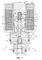
- a solenoid assembly according to the present invention is shown in Figure 1 generally at 10.
- the solenoid assembly 10 includes a solenoid portion, shown generally at 12, and a valve portion, shown generally at 14.
- the solenoid portion 12 includes a magnet core 16 connected to a plate 18.
- the plate 18 is connected to a yoke ring 20 by a press-fit connection, but it is within the scope of the invention that other types of connections may be used.
- the yoke ring 20 partially surrounds an outer surface of a coil 22, and the coil 22 at least partially surrounds a bobbin 24.
- a sleeve 26 Surrounded by the bobbin 24 is a sleeve 26, and the sleeve 26 at least partially surrounds the magnet core 16, and also at least partially surrounds an outer wall 28 formed as part of a housing 30.
- the sleeve 26 is connected to the magnet core 16 and the outer wall 28 through a laser welding process.
- the housing 30 also includes an inner wall 32, and a recess, shown generally at 34, located between the outer wall 28 and inner wall 32. Partially located in the recess 34 is an armature 36, which is able to move relative to the magnet core 16 and the housing 30.
- the armature 36 also includes a stepped portion, shown generally at 38, which is shaped to correspond to a stepped portion, shown generally at 40, formed as part of the magnet core 16.
- a spring 42 is disposed between the magnet core 16 and the armature 36. More specifically, the spring 42 is partially disposed in a recess, shown generally at 44, formed as part of the magnet core 16, and the spring 42 is also partially disposed in another recess, shown generally at 46, formed as part of the armature 36.
- the spring 42 biases the armature 36 away from the magnet core 16, the function of which will be described later.
- the spring 42 is a hot preset spring 42, which helps to ensure a constant spring preload over the lifetime use of the spring 42, and have stable force balancing between the magnetic and hydraulic forces in the solenoid assembly 10.
- the armature 36 also has an aperture 48, and a plunger 50 is press-fit into the aperture 36.
- plunger 50 may be held in place in the aperture 48 in other ways.
- the plunger 50 extends through another aperture 52 formed as part of the inner wall 32 of the housing 30, such that the plunger 50 is at least partially surrounded by the inner wall 32.
- the plunger 50 and armature 36 are also movable relative to the housing 30, such that a portion of the plunger 50 slides within the aperture 52 formed as part of the inner wall 32, and the inner wall 32 also functions as a guide to the movement of the plunger 50, and prevents the armature 36 from moving relative to the sleeve 26 in an undesirable manner.
- the housing 30 also includes an exhaust port 54, which is in fluid communication with an intermediary port 56, the intermediary port 56 is in fluid communication with a control port 58, and the control port 58 is in fluid communication with a supply port 60.
- Disposed in the intermediary port 56 is a first insert 62, and the first insert 62 includes an exhaust seat 64.
- Disposed in the supply port 60 is a second insert 66, and the second insert 66 includes a supply seat 68.
- the first insert 62 is press-fit into the intermediary port 56, and the second insert 66 is press-fit into the supply port 60.
- the plunger 50 also includes a reduced diameter portion 70 which extends through the intermediary port 56 and partially into the control port 58.
- the reduced diameter portion 70 contacts a valve, which in this embodiment is a ball 72, but it is within the scope of the invention that other types of valves may be used.
- the reduced diameter portion 70 and the ball 72 are part of the valve portion 14.
- pressurized fluid flows into the supply port 60 and is prevented from entering into the control port 58 because the spring 42 biases the valve portion 14 to a closed position when no current is applied to the coil 22 (the ball 72 is in contact with the supply seat 68 when the valve portion 14 is in the closed position, as shown in Figure 1 ).
- current is applied to the coil 22
- magnetic force is generated to overcome the force of the spring 42 applied to the armature 36, such that the armature 36 moves toward the magnet core 16, and therefore the plunger 50 also is moved away from the ball 72, allowing the ball 72 to lift off of the supply seat 68, and fluid to pass from the supply port 60 to the control port 58.
- the armature 36 and plunger 50 move close enough to the magnet core 16 to allow the ball 72 to contact the exhaust seat 64, such that all of the fluid from the supply port 60 flows into the control port 58.
- current is applied to the coil 22 to move the armature 36 and allow the ball 72 to move away from the supply seat 68, and provide a pressure balance between the supply port 60 and the control port 58.
- the current applied to the coil 22 may be varied to control the fluid passing between the supply port 60 and control port 58, and therefore control the fluid pressure in the supply port 60 and control port 58.
- a chart depicting the force balance relationship between the current applied to the coil 22, the force applied to the armature 36 by the spring 42, and the position of the armature 36 is shown in Figure 2 .
- the current shown as part of the chart in Figure 2 includes several curves depicting current verses force at multiple currents.
- the curve for the hydraulic force is shown at 96
- the curve for the spring force is shown at 98
- curve for the summation of the hydraulic force 96 and spring force 98 is shown at 100.
- FIG. 3 A chart depicting the pressure in the control port 58 versus the current applied to the coil 22 is shown in Figure 3 .
- the solenoid assembly 10 of the present invention is referred to as a "normally low" solenoid assembly, in reference to the state of the output.
- the solenoid assembly 10 When no current is applied to the coil 22 (the solenoid assembly 10 is inactive), the ball 72 is in contact with the supply seat 68, and the pressure in the control port 58 is very low or substantially zero.
- the pressure in the ports 54,58,60 may be detected using one or more pressure sensors. As the current is applied to the coil 22 and then increased, the ball 72 moves away from the supply seat 68 and closer to the exhaust seat 64, increasing the pressure in the control port 58.
- the solenoid assembly 10 also has several features to prevent debris from flowing into the area around the armature 36.
- the plunger 50 includes several ribs 74 which create a tortuous path for the flow of the fluid, and therefore limits or prevents debris from flowing past the plunger 50 and around the armature 36.
- the ribs 74 also reduce friction between the plunger 50 and the aperture 52, and the fluid in the ribs 74 also provides lubrication to reduce wear.
- the armature 36 is also coated with a Teflon coating to reduce friction between the armature 36 and the outer wall 28.
- exit apertures 76 Formed as part of the sleeve 26 are exit apertures 76, and fluid around the armature 36 is able to flow out of the exit apertures 76 and around the sleeve 26, and out one or more grooves 78 formed as part of the housing 30.
- the exit apertures 76 and the grooves 78 provide pressure equilibrium around the armature 36, such that any fluid that flows into the area around the armature 36 has little to no effect on the movement of the armature 36.
- the flow path through the exit apertures 76 and the grooves 78 creates a tortuous path to prevent dirt migration into the air gap between the armature 36 and magnet core 16 from outside of the assembly 10.
- both the supply seat 68 and exhaust seat 64 have a tapered edge, or sharp edge 68A and 64A, respectively, to balance forces under flow conditions.
- the seats 64,68 also ensure stable functionality over various temperature ranges, and control leakage over the lifetime of the assembly.
- the shape of the edges 64A,68A minimizes the hydraulic force variations at constant supply pressure during positioning of the ball 72, and ensure a stable sealing diameter and hydraulic force on the ball 72 over the lifetime of the assembly 10.
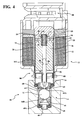
- FIG. 4-5 Another embodiment of the present invention is shown in Figures 4-5 , with like numbers referring to like elements.
- the housing 30 is not used, and the sleeve 26 is larger such that the sleeve 26 contains the valve portion 14.
- the sleeve 26 is a deep drawn part, containing all the parts of the valve portion 14.
- the sleeve 26 shown in Figure 3 is magnetic conductive to optimize the magnetic forces between the armature 36 and the magnet core 16.
- the armature 36 shown in Figure 3 has a Teflon coating to reduce friction between the armature 36 and the sleeve 26, and reduce the magnetic eccentric forces.
- the sleeve 26 in this embodiment has two portions, a large diameter portion 26A and a small diameter portion 26B.
- the armature 36 is located in the large diameter portion 26A, and the valve portion 14 is located in the small diameter portion 26B. More specifically, both of the inserts 62,66 and the ball 72 are located in the small diameter portion 26B of the sleeve 26.
- the ball 72 in this embodiment has a larger diameter than the ball 72 shown in Figure 1 , which reduces hydraulic force variations in the valve portion 14.
- the exhaust port 54 is formed as part of the large diameter portion 26A
- the control port 58 is formed as part of the small diameter portion 26B
- the supply port 60 is formed as part of the small diameter portion 26B.
- the supply port 60 shown in Figure 3 extends outwardly away from the second insert 66, and has a diameter that is smaller than the diameter of the small diameter portion 26B.
- the separation plate 80 located within the sleeve 26, and the plate 80 has an aperture 82 which the plunger 50 extends through.
- the separation plate 80 is located in the large diameter portion 26A of the sleeve 26 in an area between the armature 36 and the exhaust port 54.
- the separation plate 80 separates the valve portion 14 from the solenoid portion 12, preventing the solenoid portion 12 from being exposed to the fluid in the valve portion 14.
- the separation plate 80 is a deep drawn part, but it is within the scope of the invention that other methods may be used to form the separation plate 80.
- the yoke ring 20 shown in Figure 3 is larger than the yoke ring 20 shown in Figure 1 , and includes several retention features shown generally at 86.
- the retentions features 86 are integrally formed with the yoke ring 20, and the yoke ring 20 in this embodiment is formed as a single piece, and as a deep drawn part, but it is within the scope of the invention that other methods may be used to form the yoke ring 20.
- the sleeve 26 is connected to the yoke ring 20 through the use of a first weld connection 90, and the sleeve 26 is also connected to the magnet core 16 through the use of a second weld connection 92.
- the embodiment shown in Figure 3 also includes a cap, shown generally at 88, which connects with and is surrounded by part of the yoke ring 20.
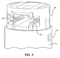
- the cap 88 is connected to the yoke ring 20 through a snap-fit connection, shown generally at 94, in Figure 5 .
- the snap fit connection 94 also functions to properly position the cap 88 relative to the yoke ring 20, such that any data marking on the cap 88 is correctly positioned as well.
- the cap 88 also protects electrical terminals 102 from becoming exposed and contaminated by the fluid.
Landscapes
- Engineering & Computer Science (AREA)
- General Engineering & Computer Science (AREA)
- Mechanical Engineering (AREA)
- Physics & Mathematics (AREA)
- Electromagnetism (AREA)
- Magnetically Actuated Valves (AREA)
- Power Engineering (AREA)
- Electromagnets (AREA)
- Details Of Valves (AREA)
Abstract
Description
- The invention relates generally to a solenoid assembly which ensures stable force balance and pressure control with magnetic and hydraulic forces.
- Solenoids are generally known, and some solenoids are used to control fluid pressure in different types of hydraulic systems. Some transmissions use open-loop systems to control the actuation of different components, and control pressure in different locations in the transmission. Some types of highly precise solenoids have been incorporated into these open-loop applications. However, many different types of solenoids have issues with contamination, and disproportionate magnetic and hydraulic forces during operation. Additionally, despite these solenoids having high levels of precision, the control units for these solenoids need to be individually calibrated in production. Accordingly, there exists a need for a solenoid assembly which overcomes the aforementioned drawbacks, and may be used as part of a closed-loop feedback control system in a transmission to eliminate the need for calibration of the controller.
- The present invention is a normally low solenoid assembly for a transmission, where the normally low solenoid assembly has a low, or zero, output when inactivated. The normally low solenoid assembly of the present invention is used for providing control over fluid pressure distribution in a transmission, where the solenoid assembly includes a solenoid portion and a valve portion, and the movement of the valve portion is controlled by the solenoid portion. There is a valve which is part of the valve portion, and a magnet core and armature which are part of the solenoid portion such that the armature moves toward and away from the magnet core.
- A plunger is connected to the armature, and in contact with the valve. A sleeve surrounds the armature and the valve portion, such that the valve portion is substantially contained within the sleeve. A valve seat is part of the valve portion and surrounded by the sleeve, and the valve is selectively in contact with the valve seat. A supply port, a control port, and an exhaust port are formed as part of the sleeve such that all three ports are in fluid communication with the valve portion.
- A return spring is located between the magnet core and the armature, the return spring biasing the armature away from the magnet core, such that the return spring biases the valve toward a closed position. A coil at least partially surrounds the sleeve, the coil being part of the solenoid portion. The armature and plunger move towards the coil when the coil is energized, allowing fluid flowing into the supply port to move the valve away from the valve seat, such that at least a portion of the fluid flows through the control port. When the coil de-energized, the valve moves towards the valve seat, and at least a portion of the fluid flows through the exhaust port.
- The sleeve includes a small diameter portion and a large diameter portion which are integrally formed together. The armature is substantially surrounded by the large diameter portion, and the valve portion is substantially surrounded by the small diameter portion. The supply port, the control port, and the exhaust port are all integrally formed as part of the small diameter portion of the sleeve. A separation plate is located within the large diameter portion of the sleeve, the separation plate separates the valve portion from the solenoid portion, and the plunger extends through the separation plate.
- The valve seat includes a first insert disposed in the small diameter portion of the sleeve, and a second insert disposed in the small diameter portion of the sleeve. The valve in one embodiment is a ball, and the ball is disposed between the first insert and the second insert. The ball is in contact with the second insert when the valve is in the closed position, and the ball moves away from the second insert and towards the first insert when the valve changes to the open position.
- Different types of manufacturing methods may be used to create the solenoid assembly. In one embodiment, the sleeve and the separation plate are deep drawn parts, but it is within the scope of the invention that other types of manufacturing methods may be used.
- In one embodiment, the solenoid assembly of the present invention is used in a closed-loop feedback control system in a hydraulic system for a transmission.
- Further areas of applicability of the present invention will become apparent from the detailed description provided hereinafter. It should be understood that the detailed description and specific examples, while indicating the preferred embodiment of the invention, are intended for purposes of illustration only and are not intended to limit the scope of the invention.
- The present invention will become more fully understood from the detailed description and the accompanying drawings, wherein:
-
Figure 1 is a sectional side view of a solenoid assembly, according to embodiments of the present invention; -
Figure 2 is a force balance diagram of a solenoid assembly, according to embodiments of the present invention; -
Figure 3 is a diagram depicting pressure versus current characteristics of a solenoid assembly, according to embodiments of the present invention; -
Figure 4 is a sectional side view of an alternate embodiment of a solenoid assembly, according to embodiments of the present invention; -
Figure 5 is a perspective view of a cap connected to a yoke, which is part an alternate embodiment of a solenoid assembly, according to embodiments of the present invention. - The following description of the preferred embodiment(s) is merely exemplary in nature and is in no way intended to limit the invention, its application, or uses.
- A solenoid assembly according to the present invention is shown in
Figure 1 generally at 10. Thesolenoid assembly 10 includes a solenoid portion, shown generally at 12, and a valve portion, shown generally at 14. Thesolenoid portion 12 includes amagnet core 16 connected to aplate 18. Theplate 18 is connected to ayoke ring 20 by a press-fit connection, but it is within the scope of the invention that other types of connections may be used. - The
yoke ring 20 partially surrounds an outer surface of acoil 22, and thecoil 22 at least partially surrounds abobbin 24. Surrounded by thebobbin 24 is asleeve 26, and thesleeve 26 at least partially surrounds themagnet core 16, and also at least partially surrounds anouter wall 28 formed as part of ahousing 30. Thesleeve 26 is connected to themagnet core 16 and theouter wall 28 through a laser welding process. Thehousing 30 also includes an inner wall 32, and a recess, shown generally at 34, located between theouter wall 28 and inner wall 32. Partially located in therecess 34 is anarmature 36, which is able to move relative to themagnet core 16 and thehousing 30. - The
armature 36 also includes a stepped portion, shown generally at 38, which is shaped to correspond to a stepped portion, shown generally at 40, formed as part of themagnet core 16. - A
spring 42 is disposed between themagnet core 16 and thearmature 36. More specifically, thespring 42 is partially disposed in a recess, shown generally at 44, formed as part of themagnet core 16, and thespring 42 is also partially disposed in another recess, shown generally at 46, formed as part of thearmature 36. Thespring 42 biases thearmature 36 away from themagnet core 16, the function of which will be described later. In one embodiment, thespring 42 is ahot preset spring 42, which helps to ensure a constant spring preload over the lifetime use of thespring 42, and have stable force balancing between the magnetic and hydraulic forces in thesolenoid assembly 10. - The
armature 36 also has anaperture 48, and aplunger 50 is press-fit into theaperture 36. However, it is within the scope of the invention that plunger 50 may be held in place in theaperture 48 in other ways. Theplunger 50 extends through another aperture 52 formed as part of the inner wall 32 of thehousing 30, such that theplunger 50 is at least partially surrounded by the inner wall 32. Theplunger 50 andarmature 36 are also movable relative to thehousing 30, such that a portion of theplunger 50 slides within the aperture 52 formed as part of the inner wall 32, and the inner wall 32 also functions as a guide to the movement of theplunger 50, and prevents thearmature 36 from moving relative to thesleeve 26 in an undesirable manner. - The
housing 30 also includes anexhaust port 54, which is in fluid communication with anintermediary port 56, theintermediary port 56 is in fluid communication with acontrol port 58, and thecontrol port 58 is in fluid communication with asupply port 60. Disposed in theintermediary port 56 is afirst insert 62, and thefirst insert 62 includes anexhaust seat 64. Disposed in thesupply port 60 is asecond insert 66, and thesecond insert 66 includes asupply seat 68. Thefirst insert 62 is press-fit into theintermediary port 56, and thesecond insert 66 is press-fit into thesupply port 60. Theplunger 50 also includes a reduceddiameter portion 70 which extends through theintermediary port 56 and partially into thecontrol port 58. The reduceddiameter portion 70 contacts a valve, which in this embodiment is aball 72, but it is within the scope of the invention that other types of valves may be used. The reduceddiameter portion 70 and theball 72 are part of thevalve portion 14. - In operation, pressurized fluid flows into the
supply port 60 and is prevented from entering into thecontrol port 58 because thespring 42 biases thevalve portion 14 to a closed position when no current is applied to the coil 22 (theball 72 is in contact with thesupply seat 68 when thevalve portion 14 is in the closed position, as shown inFigure 1 ). When current is applied to thecoil 22, magnetic force is generated to overcome the force of thespring 42 applied to thearmature 36, such that thearmature 36 moves toward themagnet core 16, and therefore theplunger 50 also is moved away from theball 72, allowing theball 72 to lift off of thesupply seat 68, and fluid to pass from thesupply port 60 to thecontrol port 58. - When the
ball 72 is in the closed position, as shown inFigure 1 , there is an air gap between thearmature 36 and themagnet core 16, and the steppedportions armature 36 andmagnet core 16 create a larger air gap between thearmature 36 and themagnet core 16, as compared to an armature and magnet core not having steppedportions armature 36 and themagnet core 16 when thecoil 22 is energized, and provides for better control over movement of thearmature 36 when thecoil 22 is energized to place thearmature 36 in intermediate positions between themagnet core 16 and thehousing 30. - If enough current is applied to the
coil 22, thearmature 36 andplunger 50 move close enough to themagnet core 16 to allow theball 72 to contact theexhaust seat 64, such that all of the fluid from thesupply port 60 flows into thecontrol port 58. However, when thesolenoid assembly 10 is used in certain applications, current is applied to thecoil 22 to move thearmature 36 and allow theball 72 to move away from thesupply seat 68, and provide a pressure balance between thesupply port 60 and thecontrol port 58. Additionally, the current applied to thecoil 22 may be varied to control the fluid passing between thesupply port 60 andcontrol port 58, and therefore control the fluid pressure in thesupply port 60 andcontrol port 58. - Once the current is no longer applied to the
coil 22, there is no longer a magnetic attraction between thearmature 36 and themagnet core 16, and thespring 42 moves theplunger 50 andarmature 36 away from themagnet core 16, and therefore moves theball 72 toward thesupply seat 68 to place thevalve portion 14 in the closed position. As this occurs, fluid in thecontrol port 58 flows through theintermediary port 56 and through theexhaust port 54. The amount of current applied to thecoil 22 may be varied to vary the position of thearmature 36,plunger 50, and therefore theball 72, to vary the amount of fluid passing from thesupply port 60 to thecontrol port 58 andexhaust port 54. A chart depicting the force balance relationship between the current applied to thecoil 22, the force applied to thearmature 36 by thespring 42, and the position of thearmature 36 is shown inFigure 2 . The current shown as part of the chart inFigure 2 includes several curves depicting current verses force at multiple currents. The curve for the hydraulic force is shown at 96, the curve for the spring force is shown at 98, and curve for the summation of thehydraulic force 96 andspring force 98 is shown at 100. - A chart depicting the pressure in the
control port 58 versus the current applied to thecoil 22 is shown inFigure 3 . Thesolenoid assembly 10 of the present invention is referred to as a "normally low" solenoid assembly, in reference to the state of the output. When no current is applied to the coil 22 (thesolenoid assembly 10 is inactive), theball 72 is in contact with thesupply seat 68, and the pressure in thecontrol port 58 is very low or substantially zero. The pressure in theports coil 22 and then increased, theball 72 moves away from thesupply seat 68 and closer to theexhaust seat 64, increasing the pressure in thecontrol port 58. This relationship of increase in current applied to thecoil 22 and increase in pressure in thecontrol port 58 is shown inFigure 3 . When theball 72 is in contact with theexhaust seat 64, the pressure in thesupply port 60 and the pressure in thecontrol port 58 are substantially equal. In one embodiment, thesolenoid assembly 10 is used as part of a closed-loop feedback control system in a transmission. - The
solenoid assembly 10 also has several features to prevent debris from flowing into the area around thearmature 36. Theplunger 50 includesseveral ribs 74 which create a tortuous path for the flow of the fluid, and therefore limits or prevents debris from flowing past theplunger 50 and around thearmature 36. Theribs 74 also reduce friction between theplunger 50 and the aperture 52, and the fluid in theribs 74 also provides lubrication to reduce wear. In one embodiment, thearmature 36 is also coated with a Teflon coating to reduce friction between thearmature 36 and theouter wall 28. - Formed as part of the
sleeve 26 areexit apertures 76, and fluid around thearmature 36 is able to flow out of theexit apertures 76 and around thesleeve 26, and out one ormore grooves 78 formed as part of thehousing 30. The exit apertures 76 and thegrooves 78 provide pressure equilibrium around thearmature 36, such that any fluid that flows into the area around thearmature 36 has little to no effect on the movement of thearmature 36. Additionally, the flow path through theexit apertures 76 and thegrooves 78 creates a tortuous path to prevent dirt migration into the air gap between thearmature 36 andmagnet core 16 from outside of theassembly 10. - To facilitate optimal contact between the
ball 72 and thesupply seat 68 and contact between theball 72 and theexhaust seat 64, both thesupply seat 68 andexhaust seat 64 have a tapered edge, orsharp edge seats edges ball 72, and ensure a stable sealing diameter and hydraulic force on theball 72 over the lifetime of theassembly 10. - Another embodiment of the present invention is shown in
Figures 4-5 , with like numbers referring to like elements. However, in this embodiment, thehousing 30 is not used, and thesleeve 26 is larger such that thesleeve 26 contains thevalve portion 14. In one embodiment, thesleeve 26 is a deep drawn part, containing all the parts of thevalve portion 14. Thesleeve 26 shown inFigure 3 is magnetic conductive to optimize the magnetic forces between thearmature 36 and themagnet core 16. In one embodiment, thearmature 36 shown inFigure 3 has a Teflon coating to reduce friction between thearmature 36 and thesleeve 26, and reduce the magnetic eccentric forces. Thesleeve 26 in this embodiment has two portions, alarge diameter portion 26A and asmall diameter portion 26B. Thearmature 36 is located in thelarge diameter portion 26A, and thevalve portion 14 is located in thesmall diameter portion 26B. More specifically, both of theinserts ball 72 are located in thesmall diameter portion 26B of thesleeve 26. Theball 72 in this embodiment has a larger diameter than theball 72 shown inFigure 1 , which reduces hydraulic force variations in thevalve portion 14. - Additionally, the
exhaust port 54 is formed as part of thelarge diameter portion 26A, thecontrol port 58 is formed as part of thesmall diameter portion 26B, and thesupply port 60 is formed as part of thesmall diameter portion 26B. Thesupply port 60 shown inFigure 3 extends outwardly away from thesecond insert 66, and has a diameter that is smaller than the diameter of thesmall diameter portion 26B. - Also, in this embodiment, there is a
separation plate 80 located within thesleeve 26, and theplate 80 has anaperture 82 which theplunger 50 extends through. Theseparation plate 80 is located in thelarge diameter portion 26A of thesleeve 26 in an area between thearmature 36 and theexhaust port 54. Theseparation plate 80 separates thevalve portion 14 from thesolenoid portion 12, preventing thesolenoid portion 12 from being exposed to the fluid in thevalve portion 14. In one embodiment, theseparation plate 80 is a deep drawn part, but it is within the scope of the invention that other methods may be used to form theseparation plate 80. - The
yoke ring 20 shown inFigure 3 is larger than theyoke ring 20 shown inFigure 1 , and includes several retention features shown generally at 86. The retentions features 86 are integrally formed with theyoke ring 20, and theyoke ring 20 in this embodiment is formed as a single piece, and as a deep drawn part, but it is within the scope of the invention that other methods may be used to form theyoke ring 20. Thesleeve 26 is connected to theyoke ring 20 through the use of a first weld connection 90, and thesleeve 26 is also connected to themagnet core 16 through the use of asecond weld connection 92. - The embodiment shown in
Figure 3 also includes a cap, shown generally at 88, which connects with and is surrounded by part of theyoke ring 20. Thecap 88 is connected to theyoke ring 20 through a snap-fit connection, shown generally at 94, inFigure 5 . The snapfit connection 94 also functions to properly position thecap 88 relative to theyoke ring 20, such that any data marking on thecap 88 is correctly positioned as well. Furthermore, thecap 88 also protectselectrical terminals 102 from becoming exposed and contaminated by the fluid. - The description of the invention is merely exemplary in nature and, thus, variations that do not depart from the gist of the invention are intended to be within the scope of the invention. Such variations are not to be regarded as a departure from the spirit and scope of the invention.
- Further Embodiments
- 1. An apparatus, comprising:
- a solenoid valve assembly, including:
- a solenoid portion;
- a valve portion controlled by the solenoid portion;
- a sleeve surrounding the solenoid portion and the valve portion; and
- a separation plate located in the sleeve between the solenoid portion and the valve portion;
- wherein the solenoid portion changes the valve portion between an open position and a closed position.
- a solenoid valve assembly, including:
- 2. The apparatus of embodiment 1, the valve portion further comprising:
- a valve; and
- a valve seat, the valve selectively in contact with the valve seat;
- wherein the valve is moved relative to the valve seat by the solenoid portion when the valve is changed between a closed position and an open position.
- 3. The apparatus of
embodiment 2, the solenoid portion further comprising:- an armature;
- a plunger connected to the armature, the plunger also in contact with the valve;
- a magnet core;
- a return spring disposed between the magnet core and the armature, such that the return spring biases the magnet core away from the armature, and the valve towards the closed position; and
- a coil at least partially surrounding the sleeve;
- wherein the movement of the armature overcomes the force applied to the armature from the return spring when a current is applied to the coil, such that the armature moves towards the magnet core, changing the valve from the closed position to the open position.
- 4. The apparatus of
embodiment 2, the valve portion further comprising:- a supply port formed as part of the sleeve;
- a control port formed as part of the sleeve, the control port selectively in fluid communication with the supply port; and
- an exhaust port formed as part of the sleeve, the exhaust port selectively in fluid communication with the control port;
- wherein fluid in the supply port applies pressure to the valve, the valve is moved relative to the valve seat by the armature and the plunger to balance fluid pressure between the supply port and the control port, and when the valve is moved from the open position to the closed position, excess fluid pressure in the control port is relieved in the exhaust port.
- 5. The apparatus of
embodiment 4, the sleeve further comprising:- a small diameter portion, the valve portion substantially surrounded by the small diameter portion; and
- a large diameter portion, the solenoid portion substantially surrounded by the large diameter portion;
- wherein the supply port, the control port, and the exhaust port are formed as part of the small diameter portion of the sleeve.
- 6. The apparatus of embodiment 5, where in the separation plate is located in the large diameter portion of the sleeve between the solenoid portion and the exhaust port.
- 7. The apparatus of
embodiment 2, the valve seat further comprising:- a first insert;
- an exhaust seat formed as part of the first insert;
- a second insert; and
- a supply seat formed as part of the second insert;
- wherein the valve is located between the first insert and the second insert such that the valve is in contact with the supply seat when the valve is in the closed position, and the valve moves away from the supply seat and towards the exhaust seat when the valve moves to the open position.
- 8. A solenoid assembly, comprising:
- a solenoid portion;
- a valve portion controlled by the solenoid portion;
- a sleeve, the valve portion substantially surrounded by the sleeve;
- a plurality of ports in fluid communication with the valve portion, the plurality of ports integrally formed as part of the sleeve;
- an armature being part of the solenoid portion, the armature being substantially surrounded by the sleeve;
- a valve being part of the valve portion, the movement of the valve controlled by the solenoid portion;
- a plunger connected to the armature and in contact with the valve;
- a valve seat being part of the valve portion, the valve selectively in contact with the valve seat; and
- a separation plate surrounded by the sleeve, the separation plate disposed between the solenoid portion and the valve portion;
- wherein the solenoid moves the armature and the plunger to control the movement of the valve relative to the valve seat, to control the fluid pressure in each of the plurality of ports.
- 9. The solenoid assembly of embodiment 8, the solenoid portion further comprising:
- a magnet core;
- a return spring disposed between the magnet core and the armature; and
- a coil substantially surrounding the armature;
- wherein the return spring biases the armature away from the magnet core, such that the valve is biased towards a closed position, and when the coil is energized, magnetic force between the armature and the magnet core overcomes the force from the return spring, moving the armature and plunger towards the magnet core, allowing the valve to move relative to the valve seat and place the valve in an open position.
- 10. The solenoid assembly of embodiment 8, the plurality of ports further comprising:
- a supply port formed as part of the sleeve, the supply port in fluid communication with the valve;
- a control port formed as part of the sleeve, the control port in fluid communication with the valve; and
- an exhaust port formed as part of the sleeve, the exhaust port in fluid communication with the valve;
- wherein fluid in the supply port applies pressure to the valve, and the valve is moved relative to the valve seat by the armature and the plunger to balance fluid pressure between the supply port and the control port, and when the valve is moved from the open position to the closed position, excess fluid pressure in the sleeve is relieved in the exhaust port.
- 11. The solenoid assembly of
embodiment 10, the sleeve further comprising:- a small diameter portion; and
- a large diameter portion integrally formed with the small diameter portion;
- wherein solenoid portion is disposed in the large diameter portion, and the valve portion is located in the small diameter portion.
- 12. The solenoid assembly of embodiment 11, wherein each of the supply port, the control port, and the exhaust port are formed as part of the small diameter portion of the sleeve.
- 13. The solenoid assembly of embodiment 11, where in the separation plate is located in the large diameter portion of the sleeve between the exhaust port and the armature.
- 14. The solenoid assembly of embodiment 8, the valve seat further comprising:
- a first insert disposed in the sleeve in proximity to the valve, the first insert being part of the valve portion;
- an exhaust seat formed as part of the first insert;
- a second insert disposed in the sleeve in proximity to the valve, the second insert being part of the valve portion;
- a supply seat formed as part of the second insert;
- wherein the valve is in contact with the supply seat when the valve is in the closed position, and the valve moves away from the supply seat and towards the exhaust seat when the valve is moved to the open position.
- 15. A solenoid assembly for a transmission, comprising:
- a solenoid portion;
- a valve portion, the movement of the valve portion controlled by the solenoid portion;
- a valve being part of the valve portion;
- a magnet core being part of the solenoid portion;
- an armature being part of the solenoid portion, the armature moveable toward and away from the magnet core;
- a return spring disposed between the magnet core and the armature, the return spring biasing the armature away from the magnet core, such that the return spring biases the valve toward a closed position;
- a plunger connected to the armature, and in contact with the valve;
- a sleeve surrounding the armature and the valve portion, such that the valve portion is substantially contained within the sleeve;
- a supply port formed as part of the sleeve, such that the supply port receives fluid and the supply port is in fluid communication with the valve portion;
- a valve seat being part of the valve portion and surrounded by the sleeve, the valve selectively in contact with the valve seat;
- a control port formed as part of the sleeve such that the control port is in fluid communication with the valve portion;
- an exhaust port formed as part of the sleeve, such that the exhaust port is in fluid communication with the valve portion;
- a coil at least partially surrounding the sleeve, the coil being part of the solenoid portion; and
- a separation plate located within the sleeve, the separation plate separating the valve portion from the solenoid portion, the plunger extending through the separation plate;
- wherein, the armature and plunger move towards the magnet core when the coil is energized, allowing fluid flowing into the supply port to move the valve relative to the valve seat, such that at least a portion of the fluid flows through the control port, and when the coil de-energized, the valve moves relative to the valve seat such that at least a portion of the fluid flows through the exhaust port.
- 16. The solenoid assembly of embodiment 15, the sleeve further comprising:
- a small diameter portion; and
- a large diameter portion integrally formed with the small diameter portion;
- wherein the armature is substantially surrounded by the large diameter portion, and the valve portion is substantially surrounded by the small diameter portion.
- 17. The solenoid assembly of
embodiment 16, wherein the supply port, the control port, and the exhaust port are all integrally formed as part of the small diameter portion of the sleeve. - 18. The solenoid assembly of
embodiment 16, wherein the separation plate is disposed in the large diameter portion of the sleeve. - 19. The solenoid assembly of
embodiment 16, the valve portion further comprising:- a first insert disposed in the small diameter portion of the sleeve;
- an exhaust seat formed as part of the first insert;
- a second insert disposed in the small diameter portion of the sleeve; and
- a supply seat formed as part of the second insert;
- wherein the valve is in contact with the supply seat when the valve is in the closed position, and the valve moves away from the supply seat and towards the exhaust seat when the valve is moved to the open position.
- 20. The solenoid assembly of embodiment 15, wherein the separation plate is located in the sleeve between the exhaust port and the armature.
Claims (15)
- An apparatus, comprising:a solenoid valve assembly, including:a solenoid portion;a valve portion controlled by the solenoid portion;a sleeve surrounding the solenoid portion and the valve portion; anda separation plate located in the sleeve between the solenoid portion and the valve portion;wherein the solenoid portion changes the valve portion between an open position and a closed position.
- The apparatus of claim 1, the valve portion further comprising:a valve; anda valve seat, the valve selectively in contact with the valve seat;wherein the valve is moved relative to the valve seat by the solenoid portion when the valve is changed between a closed position and an open position.
- The apparatus of claim 2, the solenoid portion further comprising:an armature;a plunger connected to the armature, the plunger also in contact with the valve;a magnet core;a return spring disposed between the magnet core and the armature, such that the return spring biases the magnet core away from the armature, and the valve towards the closed position; anda coil at least partially surrounding the sleeve;wherein the movement of the armature overcomes the force applied to the armature from the return spring when a current is applied to the coil, such that the armature moves towards the magnet core, changing the valve from the closed position to the open position.
- The apparatus of claim 2 or 3, the valve portion further comprising:a supply port formed as part of the sleeve;a control port formed as part of the sleeve, the control port selectively in fluid communication with the supply port; andan exhaust port formed as part of the sleeve, the exhaust port selectively in fluid communication with the control port;wherein fluid in the supply port applies pressure to the valve, the valve is moved relative to the valve seat by the armature and the plunger to balance fluid pressure between the supply port and the control port, and when the valve is moved from the open position to the closed position, excess fluid pressure in the control port is relieved in the exhaust port.
- The apparatus of any of the claims 2-4, the sleeve further comprising:a small diameter portion, the valve portion substantially surrounded by the small diameter portion; anda large diameter portion, the solenoid portion substantially surrounded by the large diameter portion;wherein the supply port, the control port, and the exhaust port are formed as part of the small diameter portion of the sleeve.
- The apparatus of any of the claims 2-5, the valve seat further comprising:a first insert;an exhaust seat formed as part of the first insert;a second insert; anda supply seat formed as part of the second insert;wherein the valve is located between the first insert and the second insert such that the valve is in contact with the supply seat when the valve is in the closed position, and the valve moves away from the supply seat and towards the exhaust seat when the valve moves to the open position.
- A solenoid assembly, comprising:a solenoid portion;a valve portion controlled by the solenoid portion;a sleeve, the valve portion substantially surrounded by the sleeve;a plurality of ports in fluid communication with the valve portion, the plurality of ports integrally formed as part of the sleeve;an armature being part of the solenoid portion, the armature being substantially surrounded by the sleeve;a valve being part of the valve portion, the movement of the valve controlled by the solenoid portion;a plunger connected to the armature and in contact with the valve;a valve seat being part of the valve portion, the valve selectively in contact with the valve seat; anda separation plate surrounded by the sleeve, the separation plate disposed between the solenoid portion and the valve portion;wherein the solenoid moves the armature and the plunger to control the movement of the valve relative to the valve seat, to control the fluid pressure in each of the plurality of ports.
- The solenoid assembly of claim 7, the solenoid portion further comprising:a magnet core;a return spring disposed between the magnet core and the armature; anda coil substantially surrounding the armature;wherein the return spring biases the armature away from the magnet core, such that the valve is biased towards a closed position, and when the coil is energized, magnetic force between the armature and the magnet core overcomes the force from the return spring, moving the armature and plunger towards the magnet core, allowing the valve to move relative to the valve seat and place the valve in an open position.
- The solenoid assembly of claim 7 or 8, the plurality of ports further comprising:a supply port formed as part of the sleeve, the supply port in fluid communication with the valve;a control port formed as part of the sleeve, the control port in fluid communication with the valve; andan exhaust port formed as part of the sleeve, the exhaust port in fluid communication with the valve;wherein fluid in the supply port applies pressure to the valve, and the valve is moved relative to the valve seat by the armature and the plunger to balance fluid pressure between the supply port and the control port, and when the valve is moved from the open position to the closed position, excess fluid pressure in the sleeve is relieved in the exhaust port.
- The solenoid assembly of claim 9, the sleeve further comprising:a small diameter portion; anda large diameter portion integrally formed with the small diameter portion;wherein solenoid portion is disposed in the large diameter portion, and the valve portion is located in the small diameter portion.
- The solenoid assembly of claim 10, wherein:each of the supply port, the control port, and the exhaust port are formed as part of the small diameter portion of the sleeve and/or the separation plate is located in the large diameter portion of the sleeve between the exhaust port and the armature.
- The solenoid assembly of any of the claims 7-11, the valve seat further comprising:a first insert disposed in the sleeve in proximity to the valve, the first insert being part of the valve portion;an exhaust seat formed as part of the first insert;a second insert disposed in the sleeve in proximity to the valve, the second insert being part of the valve portion;a supply seat formed as part of the second insert;wherein the valve is in contact with the supply seat when the valve is in the closed position, and the valve moves away from the supply seat and towards the exhaust seat when the valve is moved to the open position.
- A solenoid assembly for a transmission, comprising:a solenoid portion;a valve portion, the movement of the valve portion controlled by the solenoid portion;a valve being part of the valve portion;a magnet core being part of the solenoid portion;an armature being part of the solenoid portion, the armature moveable toward and away from the magnet core;a return spring disposed between the magnet core and the armature, the return spring biasing the armature away from the magnet core, such that the return spring biases the valve toward a closed position;a plunger connected to the armature, and in contact with the valve;a sleeve surrounding the armature and the valve portion, such that the valve portion is substantially contained within the sleeve;a supply port formed as part of the sleeve, such that the supply port receives fluid and the supply port is in fluid communication with the valve portion;a valve seat being part of the valve portion and surrounded by the sleeve, the valve selectively in contact with the valve seat;a control port formed as part of the sleeve such that the control port is in fluid communication with the valve portion;an exhaust port formed as part of the sleeve, such that the exhaust port is in fluid communication with the valve portion;a coil at least partially surrounding the sleeve, the coil being part of the solenoid portion; anda separation plate located within the sleeve, the separation plate separating the valve portion from the solenoid portion, the plunger extending through the separation plate;wherein, the armature and plunger move towards the magnet core when the coil is energized, allowing fluid flowing into the supply port to move the valve relative to the valve seat, such that at least a portion of the fluid flows through the control port, and when the coil de-energized, the valve moves relative to the valve seat such that at least a portion of the fluid flows through the exhaust port.
- The solenoid assembly of claim 13, the sleeve further comprising:a small diameter portion; anda large diameter portion integrally formed with the small diameter portion;wherein the armature is substantially surrounded by the large diameter portion, and the valve portion is substantially surrounded by the small diameter portion.
- The solenoid assembly of claim 13 or 14, wherein:the supply port, the control port, and the exhaust port are all integrally formed as part of a small diameter portion of the sleeve, and/or the separation plate is disposed in a large diameter portion of the sleeve and/or the separation plate is located in the sleeve between the exhaust port and the armature.
Applications Claiming Priority (2)
| Application Number | Priority Date | Filing Date | Title |
|---|---|---|---|
| US201361891007P | 2013-10-15 | 2013-10-15 | |
| US14/489,675 US9377124B2 (en) | 2013-10-15 | 2014-09-18 | Normally low solenoid valve assembly |
Publications (2)
| Publication Number | Publication Date |
|---|---|
| EP2868952A1 true EP2868952A1 (en) | 2015-05-06 |
| EP2868952B1 EP2868952B1 (en) | 2019-03-06 |
Family
ID=51628002
Family Applications (1)
| Application Number | Title | Priority Date | Filing Date |
|---|---|---|---|
| EP14186377.9A Active EP2868952B1 (en) | 2013-10-15 | 2014-09-25 | Normally low solenoid valve assembly |
Country Status (5)
| Country | Link |
|---|---|
| US (1) | US9377124B2 (en) |
| EP (1) | EP2868952B1 (en) |
| JP (1) | JP5930339B2 (en) |
| KR (1) | KR101628235B1 (en) |
| CN (1) | CN104776260B (en) |
Families Citing this family (15)
| Publication number | Priority date | Publication date | Assignee | Title |
|---|---|---|---|---|
| DE102015224421A1 (en) * | 2015-12-07 | 2017-06-08 | Robert Bosch Gmbh | Electromagnetically actuated inlet valve and high-pressure pump with inlet valve |
| KR101929810B1 (en) * | 2017-01-02 | 2018-12-18 | 주식회사 유니크 | Solenoid |
| EP3364015B8 (en) * | 2017-02-15 | 2020-06-03 | Vitesco Technologies GmbH | Electromagnetic switching valve and high-pressure fuel pump |
| US10544842B2 (en) * | 2017-03-24 | 2020-01-28 | Ford Global Technologies, Llc | One-way clutch for a vehicle |
| US11009139B2 (en) * | 2017-05-19 | 2021-05-18 | Aisin Aw Co., Ltd. | Relief valve |
| CN108223886B (en) * | 2017-08-08 | 2019-11-08 | 河南航天液压气动技术有限公司 | A kind of proportional flow control valve and its Electromagnetic Control mechanism |
| US10753498B2 (en) * | 2018-01-25 | 2020-08-25 | Mac Valves, Inc. | Flow-through liquid valve |
| EP3575645A1 (en) * | 2018-06-01 | 2019-12-04 | Hamilton Sundstrand Corporation | Device for pilot valve |
| JP7377036B2 (en) * | 2019-09-09 | 2023-11-09 | カヤバ株式会社 | Solenoids, solenoid valves, and shock absorbers |
| JP7377034B2 (en) * | 2019-09-09 | 2023-11-09 | カヤバ株式会社 | Solenoids, solenoid valves, and shock absorbers |
| CN112431930A (en) * | 2020-11-23 | 2021-03-02 | 石家庄禾柏生物技术股份有限公司 | Sealing valve and liquid outlet structure comprising same |
| CN113483140A (en) * | 2021-07-22 | 2021-10-08 | 舍弗勒技术股份两合公司 | Hydraulic actuator |
| WO2023036253A1 (en) * | 2021-09-10 | 2023-03-16 | 浙江盾安人工环境股份有限公司 | Solenoid valve |
| CN115789269A (en) * | 2021-09-10 | 2023-03-14 | 浙江盾安人工环境股份有限公司 | Electromagnetic valve |
| EP4202271B1 (en) * | 2021-12-23 | 2024-09-11 | AVS, Ingenieur J.C. Römer GmbH | Fluid valve with a magnetic drive unit |
Citations (7)
| Publication number | Priority date | Publication date | Assignee | Title |
|---|---|---|---|---|
| US4165762A (en) * | 1978-02-21 | 1979-08-28 | International Telephone And Telegraph Corporation | Latching valve |
| DE19624897A1 (en) * | 1996-06-21 | 1998-01-08 | Mannesmann Sachs Ag | Damping valve with adjustable damping force |
| DE10047399A1 (en) * | 2000-09-26 | 2002-04-11 | Continental Teves Ag & Co Ohg | Electromagnetic valve, especially for hydraulic brake system with slip control, has restoring spring supported on stop arranged near joint between valve seat body and valve housing |
| WO2003091079A1 (en) * | 2002-04-26 | 2003-11-06 | Continental Teves Ag & Co. Ohg | Electromagnetic valve, especially for slip regulated motor vehicle brake systems |
| DE102010002216A1 (en) * | 2010-02-23 | 2011-08-25 | Robert Bosch GmbH, 70469 | Solenoid valve with immersion stage for controlling a fluid |
| KR101239704B1 (en) * | 2011-12-28 | 2013-03-06 | 주식회사 만도 | Solenoid valve for brake system |
| DE102012202485A1 (en) * | 2012-02-17 | 2013-08-22 | Zf Friedrichshafen Ag | Adjustable damper valve device for a vibration damper |
Family Cites Families (37)
| Publication number | Priority date | Publication date | Assignee | Title |
|---|---|---|---|---|
| US4578662A (en) * | 1984-10-11 | 1986-03-25 | Lectron Products, Inc. | Solenoid assembly |
| DE3518978A1 (en) * | 1985-05-25 | 1986-11-27 | Robert Bosch Gmbh, 7000 Stuttgart | ELECTROMAGNETIC VALVE |
| US4783049A (en) * | 1986-03-24 | 1988-11-08 | Lectron Products, Inc. | Electrically operated automatic transmission controller assembly |
| JPS63103105U (en) | 1986-12-24 | 1988-07-04 | ||
| JPH0224177U (en) * | 1988-08-02 | 1990-02-16 | ||
| US4998559A (en) * | 1988-09-13 | 1991-03-12 | Coltec Industries Inc. | Solenoid operated pressure control valve |
| JPH03157576A (en) * | 1989-11-15 | 1991-07-05 | Aisin Aw Co Ltd | Three-way solenoid valve and manufacture thereof |
| JPH03199789A (en) * | 1989-12-28 | 1991-08-30 | Aisin Aw Co Ltd | Electromagnetic valve |
| US5050642A (en) * | 1990-08-23 | 1991-09-24 | Siemens Automotive L.P. | Pressure-compensated three-way solenoid valve |
| US5368274A (en) * | 1992-09-17 | 1994-11-29 | Wilson Greatbatch Ltd. | Low power electromagnetic valve |
| US5651391A (en) * | 1996-05-06 | 1997-07-29 | Borg-Warner Automotive, Inc. | Three-way solenoid valve |
| JP2000154883A (en) | 1998-11-18 | 2000-06-06 | Toyota Motor Corp | Solenoid valve |
| US6209563B1 (en) * | 2000-01-07 | 2001-04-03 | Saturn Electronics & Engineering, Inc. | Solenoid control valve |
| US20070241298A1 (en) * | 2000-02-29 | 2007-10-18 | Kay Herbert | Electromagnetic apparatus and method for controlling fluid flow |
| DE10252231A1 (en) * | 2002-04-26 | 2003-11-06 | Continental Teves Ag & Co Ohg | Solenoid valve, in particular for slip-controlled motor vehicle brake systems |
| US6866063B2 (en) * | 2002-09-06 | 2005-03-15 | Delphi Technologies, Inc. | Low leak pressure control actuator |
| US6877526B2 (en) * | 2003-07-02 | 2005-04-12 | Delphi Technologies, Inc. | Magnetic actuator and method |
| US6997436B2 (en) * | 2003-08-26 | 2006-02-14 | Delphi Technologies, Inc. | Vehicle actuator with valve seat cushioned by o-ring |
| JP4179114B2 (en) * | 2003-09-09 | 2008-11-12 | 三菱ふそうトラック・バス株式会社 | Fluid device with a structure to prevent foreign matter from entering |
| DE10359364B4 (en) * | 2003-12-18 | 2012-10-11 | Schaeffler Technologies Gmbh & Co. Kg | Electromagnetic hydraulic valve, in particular 3/2-way switching valve for controlling a varialblen valve train of an internal combustion engine |
| DE10359363A1 (en) * | 2003-12-18 | 2005-07-14 | Ina-Schaeffler Kg | Electromagnetic hydraulic valve, in particular 3/2-way switching valve for controlling a variable valve train of an internal combustion engine |
| US7051993B2 (en) * | 2004-03-10 | 2006-05-30 | Eaton Corporation | Solenoid operated valve and method of making same |
| JP4758626B2 (en) | 2004-09-02 | 2011-08-31 | イーグル工業株式会社 | Solenoid valve |
| FR2887005B1 (en) * | 2005-06-14 | 2009-04-24 | Bontaz Ct Soc Par Actions Simp | SHOULDER RELEASE SOLENOID VALVE |
| DE102005044672A1 (en) * | 2005-09-19 | 2007-03-22 | Robert Bosch Gmbh | magnetic valve |
| US8127791B2 (en) * | 2005-12-21 | 2012-03-06 | Saturn Electronics & Engineering, Inc. | Solenoid operated fluid control valve |
| US20070284008A1 (en) * | 2006-06-13 | 2007-12-13 | Brower Brent J | Pressure regulating valve |
| US20100078507A1 (en) * | 2008-09-29 | 2010-04-01 | Short Jason C | Heated and insulated fuel injector |
| EP2376813A1 (en) * | 2009-01-09 | 2011-10-19 | Toyota Jidosha Kabushiki Kaisha | Control device for vehicular on/off control valve |
| KR100948508B1 (en) * | 2009-12-15 | 2010-03-23 | 주식회사 유니크 | Oil control valve for variable valve lift system |
| DE102010055035A1 (en) * | 2010-12-17 | 2012-06-21 | Pierburg Gmbh | Solenoid valve |
| KR20120109122A (en) | 2011-03-28 | 2012-10-08 | 주식회사 만도 | Solenoid valve for brake systerm |
| DE102011077252B4 (en) | 2011-06-09 | 2018-10-04 | Robert Bosch Gmbh | Valve for controlling a fluid |
| CN102221023A (en) * | 2011-06-20 | 2011-10-19 | 重庆华渝电气仪表总厂 | Guide normally-closed type hydraulic electromagnetic valve |
| KR101167505B1 (en) * | 2011-11-01 | 2012-07-23 | 주식회사 유니크 | Oil pump control valve |
| DE102012205503A1 (en) * | 2012-04-04 | 2013-10-10 | Continental Teves Ag & Co. Ohg | Electromagnetic valve, in particular for slip-controlled motor vehicle brake systems |
| DE102012207406A1 (en) * | 2012-05-04 | 2013-11-07 | Robert Bosch Gmbh | Valve for metering fluid |
-
2014
- 2014-09-18 US US14/489,675 patent/US9377124B2/en active Active
- 2014-09-25 EP EP14186377.9A patent/EP2868952B1/en active Active
- 2014-10-14 JP JP2014209812A patent/JP5930339B2/en active Active
- 2014-10-15 CN CN201410543703.9A patent/CN104776260B/en active Active
- 2014-10-15 KR KR1020140139174A patent/KR101628235B1/en active Active
Patent Citations (7)
| Publication number | Priority date | Publication date | Assignee | Title |
|---|---|---|---|---|
| US4165762A (en) * | 1978-02-21 | 1979-08-28 | International Telephone And Telegraph Corporation | Latching valve |
| DE19624897A1 (en) * | 1996-06-21 | 1998-01-08 | Mannesmann Sachs Ag | Damping valve with adjustable damping force |
| DE10047399A1 (en) * | 2000-09-26 | 2002-04-11 | Continental Teves Ag & Co Ohg | Electromagnetic valve, especially for hydraulic brake system with slip control, has restoring spring supported on stop arranged near joint between valve seat body and valve housing |
| WO2003091079A1 (en) * | 2002-04-26 | 2003-11-06 | Continental Teves Ag & Co. Ohg | Electromagnetic valve, especially for slip regulated motor vehicle brake systems |
| DE102010002216A1 (en) * | 2010-02-23 | 2011-08-25 | Robert Bosch GmbH, 70469 | Solenoid valve with immersion stage for controlling a fluid |
| KR101239704B1 (en) * | 2011-12-28 | 2013-03-06 | 주식회사 만도 | Solenoid valve for brake system |
| DE102012202485A1 (en) * | 2012-02-17 | 2013-08-22 | Zf Friedrichshafen Ag | Adjustable damper valve device for a vibration damper |
Also Published As
| Publication number | Publication date |
|---|---|
| US9377124B2 (en) | 2016-06-28 |
| US20150102242A1 (en) | 2015-04-16 |
| EP2868952B1 (en) | 2019-03-06 |
| CN104776260B (en) | 2018-06-08 |
| CN104776260A (en) | 2015-07-15 |
| JP5930339B2 (en) | 2016-06-08 |
| JP2015110996A (en) | 2015-06-18 |
| KR20150044008A (en) | 2015-04-23 |
| KR101628235B1 (en) | 2016-06-21 |
Similar Documents
| Publication | Publication Date | Title |
|---|---|---|
| US9377124B2 (en) | Normally low solenoid valve assembly | |
| US9945492B2 (en) | Normally high solenoid assembly | |
| CN104471505B (en) | Direct action type solenoid actuator | |
| EP0683445A1 (en) | Variable force solenoid valve | |
| EP2631516A1 (en) | Solenoid-actuated pressure control valve | |
| CN102834656A (en) | Balance poppet type solenoid valve | |
| US20070158606A1 (en) | Linear solenoid with abutted portion | |
| JP4703615B2 (en) | Bleed valve device | |
| US20090014076A1 (en) | Bleed valve apparatus | |
| US7438276B2 (en) | Electromagnetic valve for brake control | |
| JP4301318B2 (en) | Bleed valve device | |
| US9739394B2 (en) | Solenoid valve | |
| JP5513918B2 (en) | Solenoid proportional throttle valve | |
| WO2019102931A1 (en) | Solenoid valve device | |
| EP3967911B1 (en) | Solenoid valve | |
| JP7183985B2 (en) | solenoid | |
| JP7025741B2 (en) | Proportional solenoid | |
| JP2008095813A (en) | Bleed valve device | |
| JP2020051610A (en) | Spool valve and spool valve device |
Legal Events
| Date | Code | Title | Description |
|---|---|---|---|
| PUAI | Public reference made under article 153(3) epc to a published international application that has entered the european phase |
Free format text: ORIGINAL CODE: 0009012 |
|
| 17P | Request for examination filed |
Effective date: 20140925 |
|
| AK | Designated contracting states |
Kind code of ref document: A1 Designated state(s): AL AT BE BG CH CY CZ DE DK EE ES FI FR GB GR HR HU IE IS IT LI LT LU LV MC MK MT NL NO PL PT RO RS SE SI SK SM TR |
|
| AX | Request for extension of the european patent |
Extension state: BA ME |
|
| R17P | Request for examination filed (corrected) |
Effective date: 20151028 |
|
| RBV | Designated contracting states (corrected) |
Designated state(s): AL AT BE BG CH CY CZ DE DK EE ES FI FR GB GR HR HU IE IS IT LI LT LU LV MC MK MT NL NO PL PT RO RS SE SI SK SM TR |
|
| STAA | Information on the status of an ep patent application or granted ep patent |
Free format text: STATUS: EXAMINATION IS IN PROGRESS |
|
| 17Q | First examination report despatched |
Effective date: 20170118 |
|
| GRAP | Despatch of communication of intention to grant a patent |
Free format text: ORIGINAL CODE: EPIDOSNIGR1 |
|
| STAA | Information on the status of an ep patent application or granted ep patent |
Free format text: STATUS: GRANT OF PATENT IS INTENDED |
|
| INTG | Intention to grant announced |
Effective date: 20180709 |
|
| GRAJ | Information related to disapproval of communication of intention to grant by the applicant or resumption of examination proceedings by the epo deleted |
Free format text: ORIGINAL CODE: EPIDOSDIGR1 |
|
| STAA | Information on the status of an ep patent application or granted ep patent |
Free format text: STATUS: EXAMINATION IS IN PROGRESS |
|
| GRAP | Despatch of communication of intention to grant a patent |
Free format text: ORIGINAL CODE: EPIDOSNIGR1 |
|
| STAA | Information on the status of an ep patent application or granted ep patent |
Free format text: STATUS: GRANT OF PATENT IS INTENDED |
|
| INTC | Intention to grant announced (deleted) | ||
| INTG | Intention to grant announced |
Effective date: 20181022 |
|
| GRAS | Grant fee paid |
Free format text: ORIGINAL CODE: EPIDOSNIGR3 |
|
| GRAA | (expected) grant |
Free format text: ORIGINAL CODE: 0009210 |
|
| STAA | Information on the status of an ep patent application or granted ep patent |
Free format text: STATUS: THE PATENT HAS BEEN GRANTED |
|
| AK | Designated contracting states |
Kind code of ref document: B1 Designated state(s): AL AT BE BG CH CY CZ DE DK EE ES FI FR GB GR HR HU IE IS IT LI LT LU LV MC MK MT NL NO PL PT RO RS SE SI SK SM TR |
|
| REG | Reference to a national code |
Ref country code: GB Ref legal event code: FG4D |
|
| REG | Reference to a national code |
Ref country code: CH Ref legal event code: EP Ref country code: AT Ref legal event code: REF Ref document number: 1105002 Country of ref document: AT Kind code of ref document: T Effective date: 20190315 |
|
| REG | Reference to a national code |
Ref country code: DE Ref legal event code: R096 Ref document number: 602014042226 Country of ref document: DE |
|
| REG | Reference to a national code |
Ref country code: IE Ref legal event code: FG4D |
|
| REG | Reference to a national code |
Ref country code: NL Ref legal event code: MP Effective date: 20190306 |
|
| REG | Reference to a national code |
Ref country code: LT Ref legal event code: MG4D |
|
| PG25 | Lapsed in a contracting state [announced via postgrant information from national office to epo] |
Ref country code: SE Free format text: LAPSE BECAUSE OF FAILURE TO SUBMIT A TRANSLATION OF THE DESCRIPTION OR TO PAY THE FEE WITHIN THE PRESCRIBED TIME-LIMIT Effective date: 20190306 Ref country code: LT Free format text: LAPSE BECAUSE OF FAILURE TO SUBMIT A TRANSLATION OF THE DESCRIPTION OR TO PAY THE FEE WITHIN THE PRESCRIBED TIME-LIMIT Effective date: 20190306 Ref country code: FI Free format text: LAPSE BECAUSE OF FAILURE TO SUBMIT A TRANSLATION OF THE DESCRIPTION OR TO PAY THE FEE WITHIN THE PRESCRIBED TIME-LIMIT Effective date: 20190306 Ref country code: NO Free format text: LAPSE BECAUSE OF FAILURE TO SUBMIT A TRANSLATION OF THE DESCRIPTION OR TO PAY THE FEE WITHIN THE PRESCRIBED TIME-LIMIT Effective date: 20190606 |
|
| PG25 | Lapsed in a contracting state [announced via postgrant information from national office to epo] |
Ref country code: BG Free format text: LAPSE BECAUSE OF FAILURE TO SUBMIT A TRANSLATION OF THE DESCRIPTION OR TO PAY THE FEE WITHIN THE PRESCRIBED TIME-LIMIT Effective date: 20190606 Ref country code: LV Free format text: LAPSE BECAUSE OF FAILURE TO SUBMIT A TRANSLATION OF THE DESCRIPTION OR TO PAY THE FEE WITHIN THE PRESCRIBED TIME-LIMIT Effective date: 20190306 Ref country code: RS Free format text: LAPSE BECAUSE OF FAILURE TO SUBMIT A TRANSLATION OF THE DESCRIPTION OR TO PAY THE FEE WITHIN THE PRESCRIBED TIME-LIMIT Effective date: 20190306 Ref country code: NL Free format text: LAPSE BECAUSE OF FAILURE TO SUBMIT A TRANSLATION OF THE DESCRIPTION OR TO PAY THE FEE WITHIN THE PRESCRIBED TIME-LIMIT Effective date: 20190306 Ref country code: GR Free format text: LAPSE BECAUSE OF FAILURE TO SUBMIT A TRANSLATION OF THE DESCRIPTION OR TO PAY THE FEE WITHIN THE PRESCRIBED TIME-LIMIT Effective date: 20190607 Ref country code: HR Free format text: LAPSE BECAUSE OF FAILURE TO SUBMIT A TRANSLATION OF THE DESCRIPTION OR TO PAY THE FEE WITHIN THE PRESCRIBED TIME-LIMIT Effective date: 20190306 |
|
| REG | Reference to a national code |
Ref country code: AT Ref legal event code: MK05 Ref document number: 1105002 Country of ref document: AT Kind code of ref document: T Effective date: 20190306 |
|
| PG25 | Lapsed in a contracting state [announced via postgrant information from national office to epo] |
Ref country code: CZ Free format text: LAPSE BECAUSE OF FAILURE TO SUBMIT A TRANSLATION OF THE DESCRIPTION OR TO PAY THE FEE WITHIN THE PRESCRIBED TIME-LIMIT Effective date: 20190306 Ref country code: IT Free format text: LAPSE BECAUSE OF FAILURE TO SUBMIT A TRANSLATION OF THE DESCRIPTION OR TO PAY THE FEE WITHIN THE PRESCRIBED TIME-LIMIT Effective date: 20190306 Ref country code: RO Free format text: LAPSE BECAUSE OF FAILURE TO SUBMIT A TRANSLATION OF THE DESCRIPTION OR TO PAY THE FEE WITHIN THE PRESCRIBED TIME-LIMIT Effective date: 20190306 Ref country code: SK Free format text: LAPSE BECAUSE OF FAILURE TO SUBMIT A TRANSLATION OF THE DESCRIPTION OR TO PAY THE FEE WITHIN THE PRESCRIBED TIME-LIMIT Effective date: 20190306 Ref country code: AL Free format text: LAPSE BECAUSE OF FAILURE TO SUBMIT A TRANSLATION OF THE DESCRIPTION OR TO PAY THE FEE WITHIN THE PRESCRIBED TIME-LIMIT Effective date: 20190306 Ref country code: PT Free format text: LAPSE BECAUSE OF FAILURE TO SUBMIT A TRANSLATION OF THE DESCRIPTION OR TO PAY THE FEE WITHIN THE PRESCRIBED TIME-LIMIT Effective date: 20190706 Ref country code: EE Free format text: LAPSE BECAUSE OF FAILURE TO SUBMIT A TRANSLATION OF THE DESCRIPTION OR TO PAY THE FEE WITHIN THE PRESCRIBED TIME-LIMIT Effective date: 20190306 Ref country code: ES Free format text: LAPSE BECAUSE OF FAILURE TO SUBMIT A TRANSLATION OF THE DESCRIPTION OR TO PAY THE FEE WITHIN THE PRESCRIBED TIME-LIMIT Effective date: 20190306 |
|
| PG25 | Lapsed in a contracting state [announced via postgrant information from national office to epo] |
Ref country code: SM Free format text: LAPSE BECAUSE OF FAILURE TO SUBMIT A TRANSLATION OF THE DESCRIPTION OR TO PAY THE FEE WITHIN THE PRESCRIBED TIME-LIMIT Effective date: 20190306 Ref country code: PL Free format text: LAPSE BECAUSE OF FAILURE TO SUBMIT A TRANSLATION OF THE DESCRIPTION OR TO PAY THE FEE WITHIN THE PRESCRIBED TIME-LIMIT Effective date: 20190306 |
|
| REG | Reference to a national code |
Ref country code: DE Ref legal event code: R097 Ref document number: 602014042226 Country of ref document: DE |
|
| PG25 | Lapsed in a contracting state [announced via postgrant information from national office to epo] |
Ref country code: IS Free format text: LAPSE BECAUSE OF FAILURE TO SUBMIT A TRANSLATION OF THE DESCRIPTION OR TO PAY THE FEE WITHIN THE PRESCRIBED TIME-LIMIT Effective date: 20190706 Ref country code: AT Free format text: LAPSE BECAUSE OF FAILURE TO SUBMIT A TRANSLATION OF THE DESCRIPTION OR TO PAY THE FEE WITHIN THE PRESCRIBED TIME-LIMIT Effective date: 20190306 |
|
| PLBE | No opposition filed within time limit |
Free format text: ORIGINAL CODE: 0009261 |
|
| STAA | Information on the status of an ep patent application or granted ep patent |
Free format text: STATUS: NO OPPOSITION FILED WITHIN TIME LIMIT |
|
| PG25 | Lapsed in a contracting state [announced via postgrant information from national office to epo] |
Ref country code: DK Free format text: LAPSE BECAUSE OF FAILURE TO SUBMIT A TRANSLATION OF THE DESCRIPTION OR TO PAY THE FEE WITHIN THE PRESCRIBED TIME-LIMIT Effective date: 20190306 |
|
| 26N | No opposition filed |
Effective date: 20191209 |
|
| PG25 | Lapsed in a contracting state [announced via postgrant information from national office to epo] |
Ref country code: SI Free format text: LAPSE BECAUSE OF FAILURE TO SUBMIT A TRANSLATION OF THE DESCRIPTION OR TO PAY THE FEE WITHIN THE PRESCRIBED TIME-LIMIT Effective date: 20190306 |
|
| PG25 | Lapsed in a contracting state [announced via postgrant information from national office to epo] |
Ref country code: TR Free format text: LAPSE BECAUSE OF FAILURE TO SUBMIT A TRANSLATION OF THE DESCRIPTION OR TO PAY THE FEE WITHIN THE PRESCRIBED TIME-LIMIT Effective date: 20190306 |
|
| PG25 | Lapsed in a contracting state [announced via postgrant information from national office to epo] |
Ref country code: MC Free format text: LAPSE BECAUSE OF FAILURE TO SUBMIT A TRANSLATION OF THE DESCRIPTION OR TO PAY THE FEE WITHIN THE PRESCRIBED TIME-LIMIT Effective date: 20190306 |
|
| REG | Reference to a national code |
Ref country code: CH Ref legal event code: PL |
|
| PG25 | Lapsed in a contracting state [announced via postgrant information from national office to epo] |
Ref country code: LI Free format text: LAPSE BECAUSE OF NON-PAYMENT OF DUE FEES Effective date: 20190930 Ref country code: LU Free format text: LAPSE BECAUSE OF NON-PAYMENT OF DUE FEES Effective date: 20190925 Ref country code: IE Free format text: LAPSE BECAUSE OF NON-PAYMENT OF DUE FEES Effective date: 20190925 Ref country code: CH Free format text: LAPSE BECAUSE OF NON-PAYMENT OF DUE FEES Effective date: 20190930 |
|
| REG | Reference to a national code |
Ref country code: BE Ref legal event code: MM Effective date: 20190930 |
|
| PG25 | Lapsed in a contracting state [announced via postgrant information from national office to epo] |
Ref country code: BE Free format text: LAPSE BECAUSE OF NON-PAYMENT OF DUE FEES Effective date: 20190930 |
|
| GBPC | Gb: european patent ceased through non-payment of renewal fee |
Effective date: 20190925 |
|
| PG25 | Lapsed in a contracting state [announced via postgrant information from national office to epo] |
Ref country code: GB Free format text: LAPSE BECAUSE OF NON-PAYMENT OF DUE FEES Effective date: 20190925 |
|
| PG25 | Lapsed in a contracting state [announced via postgrant information from national office to epo] |
Ref country code: CY Free format text: LAPSE BECAUSE OF FAILURE TO SUBMIT A TRANSLATION OF THE DESCRIPTION OR TO PAY THE FEE WITHIN THE PRESCRIBED TIME-LIMIT Effective date: 20190306 |
|
| PG25 | Lapsed in a contracting state [announced via postgrant information from national office to epo] |
Ref country code: MT Free format text: LAPSE BECAUSE OF FAILURE TO SUBMIT A TRANSLATION OF THE DESCRIPTION OR TO PAY THE FEE WITHIN THE PRESCRIBED TIME-LIMIT Effective date: 20190306 Ref country code: HU Free format text: LAPSE BECAUSE OF FAILURE TO SUBMIT A TRANSLATION OF THE DESCRIPTION OR TO PAY THE FEE WITHIN THE PRESCRIBED TIME-LIMIT; INVALID AB INITIO Effective date: 20140925 |
|
| REG | Reference to a national code |
Ref country code: DE Ref legal event code: R081 Ref document number: 602014042226 Country of ref document: DE Owner name: VITESCO TECHNOLOGIES USA, LLC, AUBURN HILLS, US Free format text: FORMER OWNER: CONTINENTAL AUTOMOTIVE SYSTEMS, INC., 48326 AUBIRN HILLS, US Ref country code: DE Ref legal event code: R081 Ref document number: 602014042226 Country of ref document: DE Owner name: SCHAEFFLER TECHNOLOGIES AG & CO. KG, DE Free format text: FORMER OWNER: CONTINENTAL AUTOMOTIVE SYSTEMS, INC., 48326 AUBIRN HILLS, US Ref country code: DE Ref legal event code: R082 Ref document number: 602014042226 Country of ref document: DE Representative=s name: WALDMANN, ALEXANDER, DE |
|
| PG25 | Lapsed in a contracting state [announced via postgrant information from national office to epo] |
Ref country code: MK Free format text: LAPSE BECAUSE OF FAILURE TO SUBMIT A TRANSLATION OF THE DESCRIPTION OR TO PAY THE FEE WITHIN THE PRESCRIBED TIME-LIMIT Effective date: 20190306 |
|
| P01 | Opt-out of the competence of the unified patent court (upc) registered |
Effective date: 20230530 |
|
| REG | Reference to a national code |
Ref country code: DE Ref legal event code: R081 Ref document number: 602014042226 Country of ref document: DE Owner name: SCHAEFFLER TECHNOLOGIES AG & CO. KG, DE Free format text: FORMER OWNER: VITESCO TECHNOLOGIES USA, LLC, AUBURN HILLS, MI, US Ref country code: DE Ref legal event code: R082 Ref document number: 602014042226 Country of ref document: DE |
|
| PGFP | Annual fee paid to national office [announced via postgrant information from national office to epo] |
Ref country code: DE Payment date: 20250930 Year of fee payment: 12 |
|
| PGFP | Annual fee paid to national office [announced via postgrant information from national office to epo] |
Ref country code: FR Payment date: 20250922 Year of fee payment: 12 |