EP2868853A1 - Actuation system and oven comprising said actuation system - Google Patents
Actuation system and oven comprising said actuation system Download PDFInfo
- Publication number
- EP2868853A1 EP2868853A1 EP20130191079 EP13191079A EP2868853A1 EP 2868853 A1 EP2868853 A1 EP 2868853A1 EP 20130191079 EP20130191079 EP 20130191079 EP 13191079 A EP13191079 A EP 13191079A EP 2868853 A1 EP2868853 A1 EP 2868853A1
- Authority
- EP
- European Patent Office
- Prior art keywords
- actuation
- household appliance
- actuation system
- anyone
- oven
- Prior art date
- Legal status (The legal status is an assumption and is not a legal conclusion. Google has not performed a legal analysis and makes no representation as to the accuracy of the status listed.)
- Granted
Links
Images

Classifications
-
- E—FIXED CONSTRUCTIONS
- E05—LOCKS; KEYS; WINDOW OR DOOR FITTINGS; SAFES
- E05F—DEVICES FOR MOVING WINGS INTO OPEN OR CLOSED POSITION; CHECKS FOR WINGS; WING FITTINGS NOT OTHERWISE PROVIDED FOR, CONCERNED WITH THE FUNCTIONING OF THE WING
- E05F15/00—Power-operated mechanisms for wings
- E05F15/60—Power-operated mechanisms for wings using electrical actuators
-
- E—FIXED CONSTRUCTIONS
- E05—LOCKS; KEYS; WINDOW OR DOOR FITTINGS; SAFES
- E05D—HINGES OR SUSPENSION DEVICES FOR DOORS, WINDOWS OR WINGS
- E05D11/00—Additional features or accessories of hinges
-
- F—MECHANICAL ENGINEERING; LIGHTING; HEATING; WEAPONS; BLASTING
- F03—MACHINES OR ENGINES FOR LIQUIDS; WIND, SPRING, OR WEIGHT MOTORS; PRODUCING MECHANICAL POWER OR A REACTIVE PROPULSIVE THRUST, NOT OTHERWISE PROVIDED FOR
- F03G—SPRING, WEIGHT, INERTIA OR LIKE MOTORS; MECHANICAL-POWER PRODUCING DEVICES OR MECHANISMS, NOT OTHERWISE PROVIDED FOR OR USING ENERGY SOURCES NOT OTHERWISE PROVIDED FOR
- F03G7/00—Mechanical-power-producing mechanisms, not otherwise provided for or using energy sources not otherwise provided for
- F03G7/06—Mechanical-power-producing mechanisms, not otherwise provided for or using energy sources not otherwise provided for using expansion or contraction of bodies due to heating, cooling, moistening, drying or the like
- F03G7/061—Mechanical-power-producing mechanisms, not otherwise provided for or using energy sources not otherwise provided for using expansion or contraction of bodies due to heating, cooling, moistening, drying or the like characterised by the actuating element
- F03G7/0614—Mechanical-power-producing mechanisms, not otherwise provided for or using energy sources not otherwise provided for using expansion or contraction of bodies due to heating, cooling, moistening, drying or the like characterised by the actuating element using shape memory elements
-
- F—MECHANICAL ENGINEERING; LIGHTING; HEATING; WEAPONS; BLASTING
- F03—MACHINES OR ENGINES FOR LIQUIDS; WIND, SPRING, OR WEIGHT MOTORS; PRODUCING MECHANICAL POWER OR A REACTIVE PROPULSIVE THRUST, NOT OTHERWISE PROVIDED FOR
- F03G—SPRING, WEIGHT, INERTIA OR LIKE MOTORS; MECHANICAL-POWER PRODUCING DEVICES OR MECHANISMS, NOT OTHERWISE PROVIDED FOR OR USING ENERGY SOURCES NOT OTHERWISE PROVIDED FOR
- F03G7/00—Mechanical-power-producing mechanisms, not otherwise provided for or using energy sources not otherwise provided for
- F03G7/06—Mechanical-power-producing mechanisms, not otherwise provided for or using energy sources not otherwise provided for using expansion or contraction of bodies due to heating, cooling, moistening, drying or the like
- F03G7/061—Mechanical-power-producing mechanisms, not otherwise provided for or using energy sources not otherwise provided for using expansion or contraction of bodies due to heating, cooling, moistening, drying or the like characterised by the actuating element
- F03G7/0614—Mechanical-power-producing mechanisms, not otherwise provided for or using energy sources not otherwise provided for using expansion or contraction of bodies due to heating, cooling, moistening, drying or the like characterised by the actuating element using shape memory elements
- F03G7/06143—Wires
-
- F—MECHANICAL ENGINEERING; LIGHTING; HEATING; WEAPONS; BLASTING
- F24—HEATING; RANGES; VENTILATING
- F24C—DOMESTIC STOVES OR RANGES ; DETAILS OF DOMESTIC STOVES OR RANGES, OF GENERAL APPLICATION
- F24C15/00—Details
- F24C15/02—Doors specially adapted for stoves or ranges
- F24C15/028—Stoves doors
-
- E—FIXED CONSTRUCTIONS
- E05—LOCKS; KEYS; WINDOW OR DOOR FITTINGS; SAFES
- E05Y—INDEXING SCHEME ASSOCIATED WITH SUBCLASSES E05D AND E05F, RELATING TO CONSTRUCTION ELEMENTS, ELECTRIC CONTROL, POWER SUPPLY, POWER SIGNAL OR TRANSMISSION, USER INTERFACES, MOUNTING OR COUPLING, DETAILS, ACCESSORIES, AUXILIARY OPERATIONS NOT OTHERWISE PROVIDED FOR, APPLICATION THEREOF
- E05Y2201/00—Constructional elements; Accessories therefor
- E05Y2201/40—Motors; Magnets; Springs; Weights; Accessories therefor
- E05Y2201/43—Motors
-
- E—FIXED CONSTRUCTIONS
- E05—LOCKS; KEYS; WINDOW OR DOOR FITTINGS; SAFES
- E05Y—INDEXING SCHEME ASSOCIATED WITH SUBCLASSES E05D AND E05F, RELATING TO CONSTRUCTION ELEMENTS, ELECTRIC CONTROL, POWER SUPPLY, POWER SIGNAL OR TRANSMISSION, USER INTERFACES, MOUNTING OR COUPLING, DETAILS, ACCESSORIES, AUXILIARY OPERATIONS NOT OTHERWISE PROVIDED FOR, APPLICATION THEREOF
- E05Y2800/00—Details, accessories and auxiliary operations not otherwise provided for
- E05Y2800/67—Materials; Strength alteration thereof
-
- E—FIXED CONSTRUCTIONS
- E05—LOCKS; KEYS; WINDOW OR DOOR FITTINGS; SAFES
- E05Y—INDEXING SCHEME ASSOCIATED WITH SUBCLASSES E05D AND E05F, RELATING TO CONSTRUCTION ELEMENTS, ELECTRIC CONTROL, POWER SUPPLY, POWER SIGNAL OR TRANSMISSION, USER INTERFACES, MOUNTING OR COUPLING, DETAILS, ACCESSORIES, AUXILIARY OPERATIONS NOT OTHERWISE PROVIDED FOR, APPLICATION THEREOF
- E05Y2900/00—Application of doors, windows, wings or fittings thereof
- E05Y2900/30—Application of doors, windows, wings or fittings thereof for domestic appliances
- E05Y2900/308—Application of doors, windows, wings or fittings thereof for domestic appliances for ovens
-
- F—MECHANICAL ENGINEERING; LIGHTING; HEATING; WEAPONS; BLASTING
- F24—HEATING; RANGES; VENTILATING
- F24C—DOMESTIC STOVES OR RANGES ; DETAILS OF DOMESTIC STOVES OR RANGES, OF GENERAL APPLICATION
- F24C15/00—Details
- F24C15/02—Doors specially adapted for stoves or ranges
- F24C15/023—Mounting of doors, e.g. hinges, counterbalancing
Definitions
- the present invention relates generally to the field of actuation systems. More specifically, the present invention is related to an activation system for household appliances based on shape memory alloys.
- Ovens for food preparation are well-known in prior art.
- Said ovens comprise a base body forming an oven cavity with a cavity opening for receiving the food to be prepared.
- the oven comprises a door for closing the cavity opening.
- the oven door acts as thermal barrier to keep the heat energy in the cavity during operation of the oven.
- oven doors are at least partially transparent in order to enable the user to control the process of foot preparation within the closed cavity.
- the oven door may be pivotally mounted to the oven cavity by means of hinges which allow a movement of the oven door relative to the oven cavity.
- hinges which allow a movement of the oven door relative to the oven cavity.
- door arrangements which are particularly suited for actuation by actuation systems, namely a so-called drop-down door which is pivotally mounted at a horizontal rotation axis, a so-called side-opening door pivotally mounted at a vertical rotation axis or a so-called “French door” consisting of two doors being pivotally mounted at opposite sides of the oven cavity to be opened by rotating or swinging in different directions around vertical rotation axes.
- Typical oven doors are manually operated. They comprise a handle for applying manual force to the door to be opened. Furthermore, another type of ovens comprise an automatically actuated door wherein the activation is done by an electric motor.
- a drawback of known ovens comprising an automatically actuated door is that the electric motor requires a lot of space which has negative impact on the volume of the oven cavity. Furthermore, electric motors are expensive and mechanical coupling of the motor to the door to be opened is quite complex. Accordingly, there is a need for improvements of existing household appliances comprising an automatically actuated door in order to save installation space within the household appliance and to save costs and constructional expenses.
- the invention relates to an actuation system for automatic actuation of at least one element covering an opening of a household appliance.
- the opening may be a cavity opening or an opening providing access to interior parts of the household appliance.
- Said element may be a door covering a cavity of the household appliance or a covering element adapted to cover an opening of the household appliance.
- the household appliance may be an oven, a heatable drawer, a refrigerator, a freezer etc..
- the actuation system comprises at least one actuation element constituted by at least one shape memory alloy element and the actuation system is adapted to actuate the element when applying heat to the actuation element.
- the element When activating the actuation system, the element may get opened or closed.
- the inventive actuation system is significantly smaller than actuation systems comprising an electrical motor with comparable actuating performance.
- actuation systems based on shape memory alloys are less expensive because said actuators do not need rare-earth magnets like compact electrical motors of comparable performance.
- actuation systems based on shape memory alloys operate silently, so there is no noise generated while opening the element.
- the actuation element comprises a plurality of shape memory alloy wires and/or the actuation element comprises a stack of at least two laminar shape memory alloy elements.
- the actuation element comprises a planar shape and is adapted to contract to a memorized shape when heated.
- the actuation of the element may be achieved by a tensile force applied to the element and/or the body of the household appliance, respectively, to the arms of a hinge pivotally mounting the element to the household appliance.
- the actuation element comprises a curved shape and is adapted to reduce the curvature when heated.
- the actuation of the element may be achieved by a pressure applied to the element and/or the body of the household appliance, respectively, to the arms of a hinge pivotally mounting the element to the body of the household appliance.
- the actuation system is an integral part of a hinge for pivotally mounting the element to the body of the household appliance.
- Said hinge may be specifically adapted to the active principle of the actuation element thereby raising the performance of the actuation system.
- the actuation system forms an extension module to be integrated in or connected to an existing hinge.
- the extension module may be adapted to be arranged at standard hinges, especially standard household appliance hinges and a plurality of passive hinges can be retrofitted with the actuation system according to the invention.
- the actuation element is electrically heated.
- Said heating may be achieved by an electrical heating element which is thermally coupled with the SMA actuation element or said SMA actuation element heating itself by Joule heating, i.e. resistance heating.
- the invention refers to a household appliance comprising at least one element covering an opening of the household appliance.
- the household appliance comprises at least one actuation system described above for automatic actuating the at least one element.
- the household appliance may be an oven, a heatable drawer, a refrigerator, a freezer etc..
- the opening may be a cavity opening or an opening providing access to interior parts of the household appliance, for example to a frequently operated object, e.g. a water tank.
- Said element may be a door covering a cavity of the household appliance or a covering element adapted to cover an opening of the household appliance.
- the element is designed to be opened from a closed position to a maximum opening angle and the actuation system is adapted to actuate the element through a portion of the maximum opening angle.
- the opening of the element may be realized with lower technical effort.
- a handle of the element is located such that it only gets accessible to the user after the element has at least partially been opened by the actuation system. Thereby, in the closed state the handle is invisible and does not stick out laterally at the outer face of the household appliance.
- the element is pivotally mounted to the body of the household appliance by at least two hinges, wherein one of said hinges is actuated by the actuation system.
- the actuation may be realized with reduced technical effort.
- the element is pivotally mounted to the body of the household appliance by at least two hinges, wherein two or more of said hinges are actuated by the actuation system. Thereby the actuation force may be additionally raised.
- two elements are pivotally mounted at opposite sides of the body of the household appliance to be opened by rotating or swinging in different directions, wherein each element is autonomously moved by a separate actuation system.
- the activation and control of the elements may be synchronized in order to achieve desired opening characteristics.
- two elements are pivotally mounted at opposite sides of the body of the household appliance to be opened by swiveling in different directions, wherein the two elements are connected by a mechanic coupling mechanism and mechanically powered by only one actuation system.
- the actuation may be realized with reduced technical effort.
- Fig. 1 to Fig. 3 show different types of ovens 1.
- All ovens 1 comprise an oven cavity 6 with a cavity opening 6.1 and at least one oven door 2 which is adapted to cover the cavity opening 6.1.
- Fig. 1 shows a schematic side view of an oven 1 with a so-called drop-down door, i.e. the door is pivotally mounted at a lower border of the oven cavity 6.1 in order to enable the door to pivot around a lower horizontal pivot axis.
- the door is adapted to be opened from a closed position in which the cavity opening is sealed to a maximum opening angle ⁇ max .
- the maximum opening angle ⁇ max may be 90 ° or essentially 90°.
- Fig. 2 shows a schematic top view of an oven 1 with a side-opening door, i.e. the door is pivotally mounted at the left or right border of the oven cavity 6.1 in order to enable the door to pivot around a vertical pivot axis.
- the door is adapted to be opened from a closed position in which the cavity opening is sealed to a maximum opening angle ⁇ max .
- the maximum opening angle ⁇ max may be 90° or essentially 90°.
- Fig. 3 shows a schematic top view of an oven 1 with so-called "French-door” concept.
- the oven 1 comprises a pair of oven doors 2, 2' wherein a first door 2 is pivotally mounted at the left border of the oven cavity 6.1 by a first vertical pivot axis and a second door 2' is pivotally mounted at the right border of the oven cavity 6.1 by a second vertical pivot axis parallel to the first pivot axis.
- the doors 2, 2' are mounted at opposite sides of the oven cavity 6.1, wherein the first door 2 opens to the left side and the second door 2' opens to the right side.
- both doors 2, 2' are closed, the cavity opening 6.1 is covered by both doors 2, 2'.
- Both doors are adapted to be opened from a closed position in which the cavity opening 6.1 is sealed to a maximum opening angle ⁇ max .
- the maximum opening angle ⁇ max may be 90° or essentially 90°.
- Fig. 4 and 5 show actuation elements 3 for actuating an oven door 2.
- the actuation element 3 is formed by a shape memory alloy element consisting of a shape memory alloy (SMA).
- SMA shape memory alloy
- Shape memory alloy is characterized by a cold state, i.e. when the temperature of the alloy is below its martensite finish temperature.
- a shape memory alloy is also characterized by a hot state, i.e, in the temperature of the alloy is above its austenite finish temperature.
- An object formed of the alloy may be characterized by a predetermined shape. When the object is deformed in the cold state, the strain may be reversed by heating the object above its austenite finish temperature, i.e. heating the object above its austenite finish temperature will cause the object to return to its predetermined shape.
- a first type of actuation element 3 shown in fig. 4 may comprise a planar or essentially planar shape in the released, cold state.
- the geometric dimensions of the actuation element 3 are reduced, e.g. the length is reduced from a first length l 1 (cold length) to a second length l 2 (hot length), wherein l 2 ⁇ l 1 .
- the actuation element 3 is contracting to a memorized length by applying heat.
- tensile force can be applied to the oven door 2, respectively, the oven cavity 6 in order to actuated the oven door 2, i.e. the tensile force leads to an opening and/or closing of the oven door 2.
- Fig. 5 shows a second type of actuation element 3.
- the actuation element 3 comprises curved shape.
- the actuation element 3 shows a convex shape in the released, cold state.
- pressure F (as indicated by the dashed arrow) can be applied to the oven door 2, respectively, the oven cavity 6 in order to actuated the oven door 2, i.e. the pressure leads to an opening and/or closing of the oven door 2.
- actuation systems based on single shape memory alloy wires are restricted to applications where only low to medium forces occur.
- a plurality of shape memory alloy elements may be combined within the actuation system.
- Fig. 6 shows a stacked arrangement of laminar shape memory alloy elements 4b.
- the shape memory alloy elements 4b may be adapted to apply tensile force (as described before in connection with fig. 4 ) or may be adapted to apply pressure (as described before in connection with fig. 5 ). When heat is applied to the stack of shape memory alloy elements 4b, all elements are deformed leading to an increased tensile force or pressure.
- Fig. 7 shows another possibility of increasing the actuation force of the actuation system.
- the shape memory alloy element 4a shows a steel-rope-like structure with a round cross-section.
- the shape memory alloy element 4a comprises a plurality of wires consisting of shape memory alloy. When heat is applied to the plurality of wires, all wires are deformed leading to an increased tensile force.
- Fig. 8 shows a schematic integration of the actuation system comprising at least one actuation element 3 made of shape memory alloy in a hinge 5 adapted for pivotally mounting an oven door 2 to the oven cavity 6.
- the actuation element 3 may be an integral part of the hinge 5, i.e. the hinge 5 replaces a conventional hinge of the oven.
- the actuation element 3 may be adapted as extension module which may be capable of being integrated into an existing hinge 5. Thereby, it is possible to combine the extension module with different types of conventional hinges 5.
- the actuation element 3 may be thermally coupled with an electric heating element 7 for applying heat to the actuation element 3.
- the actuation element 3 may comprise a heating element embedded in the interior of the actuation element 3.
- the electric heating element 7 may be connected to the mains supply or powered via a transformer with an appropriate voltage.
- the actuation system may be adapted to open the oven door 2 from a closed position to a certain opening angle ⁇ wherein the opening angle ⁇ is smaller than the maximum opening angle ⁇ max of the oven door 2 ( ⁇ ⁇ ⁇ max ).
- the oven may comprise a handle which is not accessible by the user in the closed position of the oven door 2. If the oven door 2 is automatically opened by the actuation system to the opening angle ⁇ , the handle may be accessible and may be manually opened by the user by means of the handle.
- the oven door 2 may be mounted to the oven cavity 6 by means of at least two hinges 5, wherein only one hinge comprises an actuation system as described before.
- at least two or all hinges 5 fixing the oven door 2 at the oven cavity 6.1 comprise said actuation system and the actuation elements 3 of the actuation systems are synchronously powered in order to cause the oven door 2 to be opened.
- each door may comprise at least one actuation system based on a shape memory alloy actuation element 3.
- each door is driven by a separate actuation system.
- only one door comprises an actuation system as mentioned above and the further door is driven by a mechanically coupling between the first and second door 2, 2'. Thereby, both doors can be opened using only one actuation system.
- Fig. 9 shows as a further embodiment an oven 1 with a sliding oven door 2.
- the sliding oven door is adapted to be pulled away from the oven cavity 6 for opening the cavity and to be slid in for closing the cavity.
- the movement of the sliding oven door may be at least partially actuated by an actuation system comprising at least one SMA element.
- Fig. 10 shows as a heatable drawer 10.
- the heatable drawer comprises a sliding element 11 and a heatable cavity 12.
- the sliding element 11 is adapted to be pulled away from the heatable cavity 12 for opening the cavity and to be slid in for closing the heatable cavity 12.
- the movement of the sliding element 11 may be at least partially actuated by an actuation system comprising at least one SMA element.
- Fig. 11 shows as a further embodiment an oven 1 with a movable covering element 8.
- the covering element 8 may be constituted by the control panel or may comprise said control panel. Said control panel may comprise a user interface for operating the oven 1.
- the covering element 8 is rotatably mounted at the cavity by means of a hinge, wherein the rotation axis may be a vertical or a horizontal axis.
- the movement of the covering element 8 may be at least partially actuated by an actuation system comprising at least one SMA element.
- the covering element 8 may in a closed position cover an opening of the oven 1 and may provide access to said opening in an open position.
- a detachable part 9 of the oven may be located, for example a water tank of a steam cooker.
Landscapes
- Engineering & Computer Science (AREA)
- Chemical & Material Sciences (AREA)
- Combustion & Propulsion (AREA)
- Mechanical Engineering (AREA)
- General Engineering & Computer Science (AREA)
- Electric Ovens (AREA)
Abstract
Description
- The present invention relates generally to the field of actuation systems. More specifically, the present invention is related to an activation system for household appliances based on shape memory alloys.
- Ovens for food preparation are well-known in prior art. Said ovens comprise a base body forming an oven cavity with a cavity opening for receiving the food to be prepared. In addition, the oven comprises a door for closing the cavity opening. The oven door acts as thermal barrier to keep the heat energy in the cavity during operation of the oven. Typically, oven doors are at least partially transparent in order to enable the user to control the process of foot preparation within the closed cavity.
- The oven door may be pivotally mounted to the oven cavity by means of hinges which allow a movement of the oven door relative to the oven cavity. There are several types of door arrangements, which are particularly suited for actuation by actuation systems, namely a so-called drop-down door which is pivotally mounted at a horizontal rotation axis, a so-called side-opening door pivotally mounted at a vertical rotation axis or a so-called "French door" consisting of two doors being pivotally mounted at opposite sides of the oven cavity to be opened by rotating or swinging in different directions around vertical rotation axes.
- Typical oven doors are manually operated. They comprise a handle for applying manual force to the door to be opened. Furthermore, another type of ovens comprise an automatically actuated door wherein the activation is done by an electric motor.
- A drawback of known ovens comprising an automatically actuated door is that the electric motor requires a lot of space which has negative impact on the volume of the oven cavity. Furthermore, electric motors are expensive and mechanical coupling of the motor to the door to be opened is quite complex. Accordingly, there is a need for improvements of existing household appliances comprising an automatically actuated door in order to save installation space within the household appliance and to save costs and constructional expenses.
- It is an objective of embodiments of the invention to provide for an improved activation system for a household appliance and a household appliance with an improved door activation system. The objective is solved by the features of the independent claims. Preferred embodiments are given in the dependent claims. If not explicitly indicated otherwise, embodiments of the invention can be freely combined with each other.
- According to a first aspect of the invention, the invention relates to an actuation system for automatic actuation of at least one element covering an opening of a household appliance. The opening may be a cavity opening or an opening providing access to interior parts of the household appliance. Said element may be a door covering a cavity of the household appliance or a covering element adapted to cover an opening of the household appliance. The household appliance may be an oven, a heatable drawer, a refrigerator, a freezer etc.. The actuation system comprises at least one actuation element constituted by at least one shape memory alloy element and the actuation system is adapted to actuate the element when applying heat to the actuation element.
- When activating the actuation system, the element may get opened or closed. Advantageously, the inventive actuation system is significantly smaller than actuation systems comprising an electrical motor with comparable actuating performance. Additionally, actuation systems based on shape memory alloys are less expensive because said actuators do not need rare-earth magnets like compact electrical motors of comparable performance. Finally, in contrast to conventional electrical motors, actuation systems based on shape memory alloys operate silently, so there is no noise generated while opening the element.
- According to preferred embodiments, the actuation element comprises a plurality of shape memory alloy wires and/or the actuation element comprises a stack of at least two laminar shape memory alloy elements. Thereby, the force generated by the actuation system can be significantly increased.
- According to preferred embodiments, the actuation element comprises a planar shape and is adapted to contract to a memorized shape when heated. Thereby, the actuation of the element may be achieved by a tensile force applied to the element and/or the body of the household appliance, respectively, to the arms of a hinge pivotally mounting the element to the household appliance.
- According to preferred embodiments, the actuation element comprises a curved shape and is adapted to reduce the curvature when heated. Thereby, the actuation of the element may be achieved by a pressure applied to the element and/or the body of the household appliance, respectively, to the arms of a hinge pivotally mounting the element to the body of the household appliance.
- According to preferred embodiments, the actuation system is an integral part of a hinge for pivotally mounting the element to the body of the household appliance. Said hinge may be specifically adapted to the active principle of the actuation element thereby raising the performance of the actuation system.
- According to preferred embodiments, the actuation system forms an extension module to be integrated in or connected to an existing hinge. So, the extension module may be adapted to be arranged at standard hinges, especially standard household appliance hinges and a plurality of passive hinges can be retrofitted with the actuation system according to the invention.
- According to preferred embodiments, the actuation element is electrically heated. Said heating may be achieved by an electrical heating element which is thermally coupled with the SMA actuation element or said SMA actuation element heating itself by Joule heating, i.e. resistance heating.
- According to a second aspect, the invention refers to a household appliance comprising at least one element covering an opening of the household appliance. The household appliance comprises at least one actuation system described above for automatic actuating the at least one element. The household appliance may be an oven, a heatable drawer, a refrigerator, a freezer etc.. The opening may be a cavity opening or an opening providing access to interior parts of the household appliance, for example to a frequently operated object, e.g. a water tank. Said element may be a door covering a cavity of the household appliance or a covering element adapted to cover an opening of the household appliance.
- According to preferred embodiments, the element is designed to be opened from a closed position to a maximum opening angle and the actuation system is adapted to actuate the element through a portion of the maximum opening angle. Thereby, the opening of the element may be realized with lower technical effort. According to preferred embodiments, a handle of the element is located such that it only gets accessible to the user after the element has at least partially been opened by the actuation system. Thereby, in the closed state the handle is invisible and does not stick out laterally at the outer face of the household appliance.
- According to preferred embodiments, the element is pivotally mounted to the body of the household appliance by at least two hinges, wherein one of said hinges is actuated by the actuation system. Thereby the actuation may be realized with reduced technical effort.
- According to preferred embodiments, the element is pivotally mounted to the body of the household appliance by at least two hinges, wherein two or more of said hinges are actuated by the actuation system. Thereby the actuation force may be additionally raised.
- According to preferred embodiments, two elements are pivotally mounted at opposite sides of the body of the household appliance to be opened by rotating or swinging in different directions, wherein each element is autonomously moved by a separate actuation system. The activation and control of the elements may be synchronized in order to achieve desired opening characteristics.
- According to other preferred embodiments, two elements are pivotally mounted at opposite sides of the body of the household appliance to be opened by swiveling in different directions, wherein the two elements are connected by a mechanic coupling mechanism and mechanically powered by only one actuation system. Thereby the actuation may be realized with reduced technical effort.
- The term "essentially" or "approximately" as used in the invention means deviations from the exact value by +/- 10%, preferably by +/- 5% and/or deviations in the form of changes that are insignificant for the function.
- The various aspects of the invention, including its particular features and advantages, will be readily understood from the following detailed description and the accompanying drawings, in which:
- Fig. 1
- shows a schematic side view of an oven with a partially opened door;
- Fig. 2
- shows a schematic top view of an oven with a partially opened door;
- Fig. 3
- shows a schematic top view of an oven with partially opened "French-type" doors;
- Fig. 4
- shows a first type of shape memory alloy with a essentially planar structure;
- Fig. 5
- shows a second type of shape memory alloy with a curved structure;
- Fig. 6
- shows an actuation element comprising a stack of planar shape memory alloys;
- Fig. 7
- shows an actuation element comprising a plurality of shape memory alloy wires;
- Fig. 8
- shows a hinge with an actuation element in a schematic side view;
- Fig. 9
- shows a schematic side view of an oven with a partially opened sliding door;
- Fig. 10
- shows a schematic side view of a heatable drawer with a sliding element; and
- Fig. 11
- shows a schematic side view of an oven with a partially opened covering element.
- The present invention will now be described more fully with reference to the accompanying drawings, in which example embodiments are shown. However, this invention should not be construed as limited to the embodiments set forth herein. Throughout the following description similar reference numerals have been used to denote similar elements, parts, items or features, when applicable.
- In the following, the embodiments of the invention are described using an oven as an example of a household appliance.
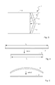
Fig. 1 to Fig. 3 show different types ofovens 1. Allovens 1 comprise anoven cavity 6 with a cavity opening 6.1 and at least oneoven door 2 which is adapted to cover the cavity opening 6.1.Fig. 1 shows a schematic side view of anoven 1 with a so-called drop-down door, i.e. the door is pivotally mounted at a lower border of the oven cavity 6.1 in order to enable the door to pivot around a lower horizontal pivot axis. The door is adapted to be opened from a closed position in which the cavity opening is sealed to a maximum opening angle αmax. The maximum opening angle αmax may be 90 ° or essentially 90°. -
Fig. 2 shows a schematic top view of anoven 1 with a side-opening door, i.e. the door is pivotally mounted at the left or right border of the oven cavity 6.1 in order to enable the door to pivot around a vertical pivot axis. The door is adapted to be opened from a closed position in which the cavity opening is sealed to a maximum opening angle αmax. The maximum opening angle αmax may be 90° or essentially 90°. -
Fig. 3 shows a schematic top view of anoven 1 with so-called "French-door" concept. Theoven 1 comprises a pair ofoven doors 2, 2' wherein afirst door 2 is pivotally mounted at the left border of the oven cavity 6.1 by a first vertical pivot axis and a second door 2' is pivotally mounted at the right border of the oven cavity 6.1 by a second vertical pivot axis parallel to the first pivot axis. In other words, thedoors 2, 2' are mounted at opposite sides of the oven cavity 6.1, wherein thefirst door 2 opens to the left side and the second door 2' opens to the right side. If bothdoors 2, 2' are closed, the cavity opening 6.1 is covered by bothdoors 2, 2'. Both doors are adapted to be opened from a closed position in which the cavity opening 6.1 is sealed to a maximum opening angle αmax. The maximum opening angle αmax may be 90° or essentially 90°. -
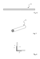
Fig. 4 and 5 show actuation elements 3 for actuating anoven door 2. Theactuation element 3 is formed by a shape memory alloy element consisting of a shape memory alloy (SMA). Shape memory alloy is characterized by a cold state, i.e. when the temperature of the alloy is below its martensite finish temperature. A shape memory alloy is also characterized by a hot state, i.e, in the temperature of the alloy is above its austenite finish temperature. An object formed of the alloy may be characterized by a predetermined shape. When the object is deformed in the cold state, the strain may be reversed by heating the object above its austenite finish temperature, i.e. heating the object above its austenite finish temperature will cause the object to return to its predetermined shape. - A first type of
actuation element 3 shown infig. 4 may comprise a planar or essentially planar shape in the released, cold state. When heat is applied to the actuation element 3 (as indicated by the arrow), the geometric dimensions of theactuation element 3 are reduced, e.g. the length is reduced from a first length l1 (cold length) to a second length l2 (hot length), wherein l2 < l1. In other words, theactuation element 3 is contracting to a memorized length by applying heat. Thereby, tensile force can be applied to theoven door 2, respectively, theoven cavity 6 in order to actuated theoven door 2, i.e. the tensile force leads to an opening and/or closing of theoven door 2. -
Fig. 5 shows a second type ofactuation element 3. Theactuation element 3 comprises curved shape. In the current embodiment, theactuation element 3 shows a convex shape in the released, cold state. By heating the actuation element 3 (as indicated by the arrow), saidactuation element 3 is activated and the curvature is minimized or theactuation element 3 reforms to a straight, planar shape. Due to the deforming, pressure F (as indicated by the dashed arrow) can be applied to theoven door 2, respectively, theoven cavity 6 in order to actuated theoven door 2, i.e. the pressure leads to an opening and/or closing of theoven door 2. - Typically, actuation systems based on single shape memory alloy wires are restricted to applications where only low to medium forces occur. In order to increase the force of the actuation system, a plurality of shape memory alloy elements may be combined within the actuation system.
-
Fig. 6 shows a stacked arrangement of laminar shapememory alloy elements 4b. The shapememory alloy elements 4b may be adapted to apply tensile force (as described before in connection withfig. 4 ) or may be adapted to apply pressure (as described before in connection withfig. 5 ). When heat is applied to the stack of shapememory alloy elements 4b, all elements are deformed leading to an increased tensile force or pressure. -
Fig. 7 shows another possibility of increasing the actuation force of the actuation system. The shapememory alloy element 4a shows a steel-rope-like structure with a round cross-section. The shapememory alloy element 4a comprises a plurality of wires consisting of shape memory alloy. When heat is applied to the plurality of wires, all wires are deformed leading to an increased tensile force. -
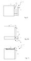
Fig. 8 shows a schematic integration of the actuation system comprising at least oneactuation element 3 made of shape memory alloy in ahinge 5 adapted for pivotally mounting anoven door 2 to theoven cavity 6. Theactuation element 3 may be an integral part of thehinge 5, i.e. thehinge 5 replaces a conventional hinge of the oven. - In another embodiment, the
actuation element 3 may be adapted as extension module which may be capable of being integrated into an existinghinge 5. Thereby, it is possible to combine the extension module with different types ofconventional hinges 5. - The
actuation element 3 may be thermally coupled with anelectric heating element 7 for applying heat to theactuation element 3. Alternatively, theactuation element 3 may comprise a heating element embedded in the interior of theactuation element 3. Theelectric heating element 7 may be connected to the mains supply or powered via a transformer with an appropriate voltage. - According to preferred embodiments, the actuation system may be adapted to open the
oven door 2 from a closed position to a certain opening angle β wherein the opening angle β is smaller than the maximum opening angle αmax of the oven door 2 (β < αmax). The oven may comprise a handle which is not accessible by the user in the closed position of theoven door 2. If theoven door 2 is automatically opened by the actuation system to the opening angle β, the handle may be accessible and may be manually opened by the user by means of the handle. - The
oven door 2 may be mounted to theoven cavity 6 by means of at least twohinges 5, wherein only one hinge comprises an actuation system as described before. In another embodiment, at least two or allhinges 5 fixing theoven door 2 at the oven cavity 6.1 comprise said actuation system and theactuation elements 3 of the actuation systems are synchronously powered in order to cause theoven door 2 to be opened. - In "French-type" ovens comprising a pair of
oven doors 2, 2' each door may comprise at least one actuation system based on a shape memoryalloy actuation element 3. In other words, each door is driven by a separate actuation system. Alternatively, only one door comprises an actuation system as mentioned above and the further door is driven by a mechanically coupling between the first andsecond door 2, 2'. Thereby, both doors can be opened using only one actuation system. -
Fig. 9 shows as a further embodiment anoven 1 with a slidingoven door 2. The sliding oven door is adapted to be pulled away from theoven cavity 6 for opening the cavity and to be slid in for closing the cavity. The movement of the sliding oven door may be at least partially actuated by an actuation system comprising at least one SMA element. -
Fig. 10 shows as aheatable drawer 10. The heatable drawer comprises a slidingelement 11 and aheatable cavity 12. The slidingelement 11 is adapted to be pulled away from theheatable cavity 12 for opening the cavity and to be slid in for closing theheatable cavity 12. The movement of the slidingelement 11 may be at least partially actuated by an actuation system comprising at least one SMA element. -
Fig. 11 shows as a further embodiment anoven 1 with a movable covering element 8. The covering element 8 may be constituted by the control panel or may comprise said control panel. Said control panel may comprise a user interface for operating theoven 1. The covering element 8 is rotatably mounted at the cavity by means of a hinge, wherein the rotation axis may be a vertical or a horizontal axis. The movement of the covering element 8 may be at least partially actuated by an actuation system comprising at least one SMA element. The covering element 8 may in a closed position cover an opening of theoven 1 and may provide access to said opening in an open position. Within said opening adetachable part 9 of the oven may be located, for example a water tank of a steam cooker. - Above, embodiments of the door actuation system according to the present invention as defined in the appended claims have been described. These should be seen as merely non-limiting examples. As understood by a skilled person, many modifications and alternative embodiments are possible within the scope of the invention.
-
- 1
- oven
- 2, 2'
- oven door
- 3
- actuation element
- 4a, 4b
- shape memory alloy element
- 5
- hinge
- 6
- oven cavity
- 6.1
- cavity opening
- 7
- electric heating element
- 8
- detachable part
- 9
- covering element
- 10
- heatable drawer
- 11
- sliding element
- 12
- heatable cavity
- αmax
- maximum opening angle
- β
- reduced opening angle
- l1
- first length
- l2
- second length
Claims (15)
- Actuation system for automatic actuation of at least one element (2, 8, 11) covering an opening of a household appliance, characterised in that,
the actuation system comprises at least one actuation element (3) constituted by at least one shape memory alloy element (4a, 4b) and the actuation system is adapted to actuate the element (2, 8, 11) when applying heat to the actuation element (3). - Actuation system according to claim 1, wherein the actuation element (3) comprises a plurality of shape memory alloy wires (4a) and/or the actuation element (3) comprises a stack of at least two laminar shape memory alloy elements (4b).
- Actuation system according to claim 1 or 2, wherein the actuation element (3) comprises a planar shape and is adapted to contract to a memorized shape when heated.
- Actuation system according to claim 1 or 2, wherein the actuation element (3) comprises a curved shape and is adapted to reduce the curvature when heated.
- Actuation system to anyone of the preceding claims, wherein the actuation system is an integral part of a hinge (5) for pivotally mounting the element (2, 8) to the body of the household appliance.
- Actuation system to anyone of the preceding claims 1 to 4,
wherein the actuation system forms an extension module to be integrated in an existing hinge (5). - Actuation system to anyone of the preceding claims, wherein the actuation element (3) is electrically heated.
- Actuation system according to anyone of the preceding claims, wherein the element actuated by the actuation element (3) is a door (2, 8, 11) covering a cavity of the household appliance and/or a covering element (2, 8, 11) to be moved relatively to the body of the household appliance.
- Household appliance comprising an at least one element (2, 8, 11) covering an opening of the household appliance, characterised in that, the household appliance comprises at least one actuation system according to anyone of the preceding claims for automatic actuating the at least one element (2, 8, 11).
- Household appliance according to claim 9, wherein the element actuated by the actuation element (3) is a door covering a cavity of the household appliance and/or a covering element to be moved relatively to the body of the household appliance.
- Household appliance according to claim 9 or 10, wherein the element (2) is adapted to be opened from a closed position to a maximum opening angle (αmax) and the actuation system is adapted to actuate the element through a portion (β) of the maximum opening angle (αmax).
- Household appliance according to anyone of the preceding claims 9 to 11, wherein a handle of the element (2) is located such that it only gets accessible to the user after the element (2) has at least partially been opened by the actuation system.
- Household appliance according to anyone of the preceding claims 9 to 12, wherein the element (2) is pivotally mounted to the body of the household appliance by at least two hinges (5), wherein one of said hinges (5) is actuated by the actuation system.
- Household appliance according to anyone of the preceding claims 9 to 12, wherein the element (2) is pivotally mounted to the body of the household appliance by at least two hinges (5), wherein two or more of said hinges (5) are actuated by the actuation system.
- Household appliance according to anyone of the preceding claims 9 to 12, comprising two element (2, 2') being pivotally mounted at opposite sides of the body of the household appliance to be opened by swinging in different directions, wherein each element (2, 2') is autonomously moved by a separate actuation system or the two elements (2, 2') are connected by a mechanic coupling mechanism and mechanically powered by only one actuation system.
Priority Applications (5)
| Application Number | Priority Date | Filing Date | Title |
|---|---|---|---|
| EP13191079.6A EP2868853B1 (en) | 2013-10-31 | 2013-10-31 | Household appliance comprising an actuation system |
| CN201480057485.6A CN105658894A (en) | 2013-10-31 | 2014-07-30 | Actuation system and oven comprising said actuation system |
| AU2014344185A AU2014344185B2 (en) | 2013-10-31 | 2014-07-30 | Actuation system and oven comprising said actuation system |
| PCT/EP2014/066326 WO2015062757A1 (en) | 2013-10-31 | 2014-07-30 | Actuation system and oven comprising said actuation system |
| US14/915,420 US10301861B2 (en) | 2013-10-31 | 2014-07-30 | Actuation system and oven comprising said actuation system |
Applications Claiming Priority (1)
| Application Number | Priority Date | Filing Date | Title |
|---|---|---|---|
| EP13191079.6A EP2868853B1 (en) | 2013-10-31 | 2013-10-31 | Household appliance comprising an actuation system |
Publications (2)
| Publication Number | Publication Date |
|---|---|
| EP2868853A1 true EP2868853A1 (en) | 2015-05-06 |
| EP2868853B1 EP2868853B1 (en) | 2018-12-26 |
Family
ID=49517326
Family Applications (1)
| Application Number | Title | Priority Date | Filing Date |
|---|---|---|---|
| EP13191079.6A Not-in-force EP2868853B1 (en) | 2013-10-31 | 2013-10-31 | Household appliance comprising an actuation system |
Country Status (5)
| Country | Link |
|---|---|
| US (1) | US10301861B2 (en) |
| EP (1) | EP2868853B1 (en) |
| CN (1) | CN105658894A (en) |
| AU (1) | AU2014344185B2 (en) |
| WO (1) | WO2015062757A1 (en) |
Cited By (2)
| Publication number | Priority date | Publication date | Assignee | Title |
|---|---|---|---|---|
| CN111853877A (en) * | 2019-04-30 | 2020-10-30 | 广东美的厨房电器制造有限公司 | cooking utensils |
| DE102019121737A1 (en) * | 2019-08-13 | 2021-02-18 | Dr. Ing. H.C. F. Porsche Aktiengesellschaft | hinge |
Families Citing this family (21)
| Publication number | Priority date | Publication date | Assignee | Title |
|---|---|---|---|---|
| US9830289B2 (en) | 2014-09-16 | 2017-11-28 | Apple Inc. | Methods and apparatus for aggregating packet transfer over a virtual bus interface |
| US10078361B2 (en) | 2014-10-08 | 2018-09-18 | Apple Inc. | Methods and apparatus for running and booting an inter-processor communication link between independently operable processors |
| US10042794B2 (en) | 2015-06-12 | 2018-08-07 | Apple Inc. | Methods and apparatus for synchronizing uplink and downlink transactions on an inter-device communication link |
| US10112745B2 (en) * | 2015-10-22 | 2018-10-30 | Autosplice, Inc. | Selectively accessible container apparatus, hinge assembly with a shape memory alloy filament, and methods |
| US10085214B2 (en) | 2016-01-27 | 2018-09-25 | Apple Inc. | Apparatus and methods for wake-limiting with an inter-device communication link |
| US10558580B2 (en) | 2016-02-29 | 2020-02-11 | Apple Inc. | Methods and apparatus for loading firmware on demand |
| US10198364B2 (en) | 2016-03-31 | 2019-02-05 | Apple Inc. | Memory access protection apparatus and methods for memory mapped access between independently operable processors |
| US10591976B2 (en) | 2016-11-10 | 2020-03-17 | Apple Inc. | Methods and apparatus for providing peripheral sub-system stability |
| US11792307B2 (en) | 2018-03-28 | 2023-10-17 | Apple Inc. | Methods and apparatus for single entity buffer pool management |
| US10585699B2 (en) | 2018-07-30 | 2020-03-10 | Apple Inc. | Methods and apparatus for verifying completion of groups of data transactions between processors |
| US10719376B2 (en) | 2018-08-24 | 2020-07-21 | Apple Inc. | Methods and apparatus for multiplexing data flows via a single data structure |
| US10846224B2 (en) | 2018-08-24 | 2020-11-24 | Apple Inc. | Methods and apparatus for control of a jointly shared memory-mapped region |
| US11558348B2 (en) | 2019-09-26 | 2023-01-17 | Apple Inc. | Methods and apparatus for emerging use case support in user space networking |
| US11829303B2 (en) | 2019-09-26 | 2023-11-28 | Apple Inc. | Methods and apparatus for device driver operation in non-kernel space |
| CN111255300A (en) * | 2020-02-27 | 2020-06-09 | 江苏精研科技股份有限公司 | A shape memory alloy assisted smart door |
| US11606302B2 (en) | 2020-06-12 | 2023-03-14 | Apple Inc. | Methods and apparatus for flow-based batching and processing |
| US11775359B2 (en) | 2020-09-11 | 2023-10-03 | Apple Inc. | Methods and apparatuses for cross-layer processing |
| US11954540B2 (en) | 2020-09-14 | 2024-04-09 | Apple Inc. | Methods and apparatus for thread-level execution in non-kernel space |
| US11799986B2 (en) | 2020-09-22 | 2023-10-24 | Apple Inc. | Methods and apparatus for thread level execution in non-kernel space |
| US11876719B2 (en) | 2021-07-26 | 2024-01-16 | Apple Inc. | Systems and methods for managing transmission control protocol (TCP) acknowledgements |
| US11882051B2 (en) | 2021-07-26 | 2024-01-23 | Apple Inc. | Systems and methods for managing transmission control protocol (TCP) acknowledgements |
Citations (3)
| Publication number | Priority date | Publication date | Assignee | Title |
|---|---|---|---|---|
| DE19817399A1 (en) * | 1997-04-21 | 1998-11-12 | Georg Dr Ing Kraft | Shape-memorising alloy drive for doors and windows |
| US20080148960A1 (en) * | 2004-02-12 | 2008-06-26 | Miele & Cie. Kg | Method For Operating a Cooking Appliance and Device For Carrying Out Said Method |
| US20130091772A1 (en) * | 2011-10-14 | 2013-04-18 | Justin Berger | Ice dispensing apparatus with a shape memory alloy actuator |
Family Cites Families (33)
| Publication number | Priority date | Publication date | Assignee | Title |
|---|---|---|---|---|
| US4842136A (en) * | 1987-02-13 | 1989-06-27 | Canon Kabushiki Kaisha | Dust-proof container having improved construction for holding a reticle therein |
| US4984953A (en) * | 1987-02-20 | 1991-01-15 | Canon Kabushiki Kaisha | Plate-like article conveying system |
| US5272888A (en) * | 1993-01-05 | 1993-12-28 | Whirlpool Corporation | Top mount refrigerator with exterior ice service |
| JPH08210241A (en) * | 1995-02-06 | 1996-08-20 | Sunpot Co Ltd | Spring device |
| US5796152A (en) * | 1997-01-24 | 1998-08-18 | Roxburgh Ltd. | Cantilevered microstructure |
| US6175989B1 (en) * | 1998-05-26 | 2001-01-23 | Lockheed Corp | Shape memory alloy controllable hinge apparatus |
| KR20010087231A (en) * | 2000-03-03 | 2001-09-15 | 레비스 스테픈 이 | Shape memory alloy bundles and actuators |
| CN2464876Y (en) * | 2001-01-21 | 2001-12-12 | 兰州西脉记忆合金股份有限公司 | Automatic open/close device for door and window |
| US6772479B2 (en) * | 2001-06-21 | 2004-08-10 | The Aerospace Corporation | Conductive shape memory metal deployment latch hinge |
| US20020195177A1 (en) * | 2001-06-21 | 2002-12-26 | The Aerospace Corporation | Conductive shape memory metal deployment latch hinge deployment method |
| CN1317478C (en) * | 2004-02-25 | 2007-05-23 | 山东大学 | Emergency door (Window) with auto induction and opening shen fire occurred |
| US20050198777A1 (en) * | 2004-03-09 | 2005-09-15 | Mabe James H. | Hinge apparatus with two-way controllable shape memory alloy (SMA) hinge pin actuator and methods of making two-way SMA parts |
| US20050247411A1 (en) * | 2004-05-04 | 2005-11-10 | Youngtak Shim | Door cover systems and methods |
| US7632361B2 (en) * | 2004-05-06 | 2009-12-15 | Tini Alloy Company | Single crystal shape memory alloy devices and methods |
| US7284786B2 (en) * | 2005-02-19 | 2007-10-23 | Gm Global Technology Operations, Inc. | Panels having active material based fold lines |
| DE102005021592A1 (en) * | 2005-05-10 | 2006-11-16 | BSH Bosch und Siemens Hausgeräte GmbH | Refrigeration device with door opening help |
| CN2795731Y (en) * | 2005-05-12 | 2006-07-12 | 甘肃省机械科学研究院 | Energy sving type memory alloy pipeline type automatic ventilator |
| WO2007038170A1 (en) * | 2005-09-23 | 2007-04-05 | Daniels William B | Passive ventilation control system |
| US7354033B1 (en) * | 2006-08-01 | 2008-04-08 | The United States Of America As Represented By The Secretary Of The Air Force | Tape-spring deployable hinge |
| US7770959B2 (en) * | 2006-10-30 | 2010-08-10 | Gm Global Technology Operations, Inc. | Door actuation systems using active materials |
| US7593524B2 (en) * | 2006-11-27 | 2009-09-22 | Nokia Corporation | Hinge arrangement |
| JP2008166465A (en) * | 2006-12-28 | 2008-07-17 | Nippon Densan Corp | Heat sink fan |
| US20100212312A1 (en) * | 2007-06-15 | 2010-08-26 | Dickory Rudduck | Stacked Morphing Actuator |
| US8282153B2 (en) * | 2007-08-31 | 2012-10-09 | GM Global Technology Operations LLC | Active material based seam concealment device |
| US8733099B2 (en) * | 2009-10-05 | 2014-05-27 | Massachusetts Institute Of Technology | Flexible actuator based on shape memory alloy sheet |
| KR101752670B1 (en) * | 2010-08-11 | 2017-07-03 | 삼성전자주식회사 | Refrigerator |
| FR2968372B1 (en) * | 2010-12-06 | 2012-12-21 | Centre Nat Etd Spatiales | BRAKE BEAM HAMMER DEVICE IN SHAPE MEMORY MATERIAL. |
| US20150015001A1 (en) * | 2011-04-28 | 2015-01-15 | Electrolux Home Products Corporation N.V. | Electric Household Appliance Door Locking Device |
| US20130000206A1 (en) * | 2011-06-30 | 2013-01-03 | GM Global Technology Operations LLC | Shape memory alloy actuator with double ended force multiplication |
| US8797703B2 (en) * | 2012-03-15 | 2014-08-05 | GM Global Technology Operations LLC | Active material actuator having a magnetorheological overload protector |
| US9334675B2 (en) * | 2012-08-15 | 2016-05-10 | Raytheon Company | Passive safety mechanism utilizing self-fracturing shape memory material |
| US9470213B2 (en) * | 2012-10-16 | 2016-10-18 | Raytheon Company | Heat-actuated release mechanism |
| US9638176B2 (en) * | 2013-05-10 | 2017-05-02 | The Boeing Company | Vortex generator using shape memory alloys |
-
2013
- 2013-10-31 EP EP13191079.6A patent/EP2868853B1/en not_active Not-in-force
-
2014
- 2014-07-30 WO PCT/EP2014/066326 patent/WO2015062757A1/en not_active Ceased
- 2014-07-30 US US14/915,420 patent/US10301861B2/en not_active Expired - Fee Related
- 2014-07-30 CN CN201480057485.6A patent/CN105658894A/en active Pending
- 2014-07-30 AU AU2014344185A patent/AU2014344185B2/en not_active Ceased
Patent Citations (3)
| Publication number | Priority date | Publication date | Assignee | Title |
|---|---|---|---|---|
| DE19817399A1 (en) * | 1997-04-21 | 1998-11-12 | Georg Dr Ing Kraft | Shape-memorising alloy drive for doors and windows |
| US20080148960A1 (en) * | 2004-02-12 | 2008-06-26 | Miele & Cie. Kg | Method For Operating a Cooking Appliance and Device For Carrying Out Said Method |
| US20130091772A1 (en) * | 2011-10-14 | 2013-04-18 | Justin Berger | Ice dispensing apparatus with a shape memory alloy actuator |
Cited By (2)
| Publication number | Priority date | Publication date | Assignee | Title |
|---|---|---|---|---|
| CN111853877A (en) * | 2019-04-30 | 2020-10-30 | 广东美的厨房电器制造有限公司 | cooking utensils |
| DE102019121737A1 (en) * | 2019-08-13 | 2021-02-18 | Dr. Ing. H.C. F. Porsche Aktiengesellschaft | hinge |
Also Published As
| Publication number | Publication date |
|---|---|
| US20160208539A1 (en) | 2016-07-21 |
| AU2014344185B2 (en) | 2017-12-21 |
| WO2015062757A1 (en) | 2015-05-07 |
| US10301861B2 (en) | 2019-05-28 |
| EP2868853B1 (en) | 2018-12-26 |
| AU2014344185A1 (en) | 2016-03-10 |
| CN105658894A (en) | 2016-06-08 |
Similar Documents
| Publication | Publication Date | Title |
|---|---|---|
| US10301861B2 (en) | Actuation system and oven comprising said actuation system | |
| US10301866B2 (en) | Hinge for household appliance such as oven | |
| CN108369013B (en) | Cooking appliance having a door opener for automatically setting a door in an intermediate position and method for opening a door of a cooking appliance | |
| CN104968881B (en) | Hinge | |
| CN105089388B (en) | Flush door handle and heated sealing with marmem actuator | |
| AU2012203141B2 (en) | Household appliance with a door and a handle | |
| EP3143336B1 (en) | Windowed door for a cooking appliance | |
| KR100837009B1 (en) | Double doors | |
| TW200848593A (en) | Pusher for movable furniture elements | |
| JP2014525293A (en) | Furniture comprising an inner body that can be raised and lowered and a leaf that covers it | |
| CN106164359A (en) | Locking device for domestic appliance door | |
| CN203704561U (en) | Vacuum oven with three doors | |
| EP3431689B1 (en) | Door hinge system for a pivotng door of a domestic appliance | |
| CN110214251A (en) | Heating device | |
| US20080148960A1 (en) | Method For Operating a Cooking Appliance and Device For Carrying Out Said Method | |
| TW200938789A (en) | Refrigerator | |
| CN107960877B (en) | Oven capable of automatically opening and closing door | |
| CN111053459A (en) | Baking oven | |
| CN109276157A (en) | A kind of novel baking oven | |
| CN111616608B (en) | Baking oven | |
| US7185925B2 (en) | Motorized oven door lock mechanism with pull-in capabilities | |
| EP2085725A3 (en) | Refrigerator and method of controlling the same | |
| EP2789941B1 (en) | Refrigerator | |
| WO2010078894A2 (en) | Household appliance, in particular oven | |
| CN211673842U (en) | oven |
Legal Events
| Date | Code | Title | Description |
|---|---|---|---|
| PUAI | Public reference made under article 153(3) epc to a published international application that has entered the european phase |
Free format text: ORIGINAL CODE: 0009012 |
|
| 17P | Request for examination filed |
Effective date: 20131031 |
|
| AK | Designated contracting states |
Kind code of ref document: A1 Designated state(s): AL AT BE BG CH CY CZ DE DK EE ES FI FR GB GR HR HU IE IS IT LI LT LU LV MC MK MT NL NO PL PT RO RS SE SI SK SM TR |
|
| AX | Request for extension of the european patent |
Extension state: BA ME |
|
| R17P | Request for examination filed (corrected) |
Effective date: 20151023 |
|
| RBV | Designated contracting states (corrected) |
Designated state(s): AL AT BE BG CH CY CZ DE DK EE ES FI FR GB GR HR HU IE IS IT LI LT LU LV MC MK MT NL NO PL PT RO RS SE SI SK SM TR |
|
| STAA | Information on the status of an ep patent application or granted ep patent |
Free format text: STATUS: EXAMINATION IS IN PROGRESS |
|
| 17Q | First examination report despatched |
Effective date: 20170201 |
|
| GRAP | Despatch of communication of intention to grant a patent |
Free format text: ORIGINAL CODE: EPIDOSNIGR1 |
|
| STAA | Information on the status of an ep patent application or granted ep patent |
Free format text: STATUS: GRANT OF PATENT IS INTENDED |
|
| INTG | Intention to grant announced |
Effective date: 20180723 |
|
| GRAS | Grant fee paid |
Free format text: ORIGINAL CODE: EPIDOSNIGR3 |
|
| GRAA | (expected) grant |
Free format text: ORIGINAL CODE: 0009210 |
|
| STAA | Information on the status of an ep patent application or granted ep patent |
Free format text: STATUS: THE PATENT HAS BEEN GRANTED |
|
| AK | Designated contracting states |
Kind code of ref document: B1 Designated state(s): AL AT BE BG CH CY CZ DE DK EE ES FI FR GB GR HR HU IE IS IT LI LT LU LV MC MK MT NL NO PL PT RO RS SE SI SK SM TR |
|
| REG | Reference to a national code |
Ref country code: GB Ref legal event code: FG4D |
|
| REG | Reference to a national code |
Ref country code: CH Ref legal event code: EP |
|
| REG | Reference to a national code |
Ref country code: AT Ref legal event code: REF Ref document number: 1081651 Country of ref document: AT Kind code of ref document: T Effective date: 20190115 |
|
| REG | Reference to a national code |
Ref country code: DE Ref legal event code: R096 Ref document number: 602013048696 Country of ref document: DE |
|
| REG | Reference to a national code |
Ref country code: IE Ref legal event code: FG4D |
|
| PG25 | Lapsed in a contracting state [announced via postgrant information from national office to epo] |
Ref country code: LV Free format text: LAPSE BECAUSE OF FAILURE TO SUBMIT A TRANSLATION OF THE DESCRIPTION OR TO PAY THE FEE WITHIN THE PRESCRIBED TIME-LIMIT Effective date: 20181226 Ref country code: NO Free format text: LAPSE BECAUSE OF FAILURE TO SUBMIT A TRANSLATION OF THE DESCRIPTION OR TO PAY THE FEE WITHIN THE PRESCRIBED TIME-LIMIT Effective date: 20190326 Ref country code: BG Free format text: LAPSE BECAUSE OF FAILURE TO SUBMIT A TRANSLATION OF THE DESCRIPTION OR TO PAY THE FEE WITHIN THE PRESCRIBED TIME-LIMIT Effective date: 20190326 Ref country code: LT Free format text: LAPSE BECAUSE OF FAILURE TO SUBMIT A TRANSLATION OF THE DESCRIPTION OR TO PAY THE FEE WITHIN THE PRESCRIBED TIME-LIMIT Effective date: 20181226 Ref country code: HR Free format text: LAPSE BECAUSE OF FAILURE TO SUBMIT A TRANSLATION OF THE DESCRIPTION OR TO PAY THE FEE WITHIN THE PRESCRIBED TIME-LIMIT Effective date: 20181226 Ref country code: FI Free format text: LAPSE BECAUSE OF FAILURE TO SUBMIT A TRANSLATION OF THE DESCRIPTION OR TO PAY THE FEE WITHIN THE PRESCRIBED TIME-LIMIT Effective date: 20181226 |
|
| REG | Reference to a national code |
Ref country code: NL Ref legal event code: MP Effective date: 20181226 |
|
| REG | Reference to a national code |
Ref country code: LT Ref legal event code: MG4D |
|
| PG25 | Lapsed in a contracting state [announced via postgrant information from national office to epo] |
Ref country code: GR Free format text: LAPSE BECAUSE OF FAILURE TO SUBMIT A TRANSLATION OF THE DESCRIPTION OR TO PAY THE FEE WITHIN THE PRESCRIBED TIME-LIMIT Effective date: 20190327 Ref country code: RS Free format text: LAPSE BECAUSE OF FAILURE TO SUBMIT A TRANSLATION OF THE DESCRIPTION OR TO PAY THE FEE WITHIN THE PRESCRIBED TIME-LIMIT Effective date: 20181226 Ref country code: AL Free format text: LAPSE BECAUSE OF FAILURE TO SUBMIT A TRANSLATION OF THE DESCRIPTION OR TO PAY THE FEE WITHIN THE PRESCRIBED TIME-LIMIT Effective date: 20181226 Ref country code: SE Free format text: LAPSE BECAUSE OF FAILURE TO SUBMIT A TRANSLATION OF THE DESCRIPTION OR TO PAY THE FEE WITHIN THE PRESCRIBED TIME-LIMIT Effective date: 20181226 |
|
| REG | Reference to a national code |
Ref country code: AT Ref legal event code: MK05 Ref document number: 1081651 Country of ref document: AT Kind code of ref document: T Effective date: 20181226 |
|
| PG25 | Lapsed in a contracting state [announced via postgrant information from national office to epo] |
Ref country code: NL Free format text: LAPSE BECAUSE OF FAILURE TO SUBMIT A TRANSLATION OF THE DESCRIPTION OR TO PAY THE FEE WITHIN THE PRESCRIBED TIME-LIMIT Effective date: 20181226 |
|
| PG25 | Lapsed in a contracting state [announced via postgrant information from national office to epo] |
Ref country code: CZ Free format text: LAPSE BECAUSE OF FAILURE TO SUBMIT A TRANSLATION OF THE DESCRIPTION OR TO PAY THE FEE WITHIN THE PRESCRIBED TIME-LIMIT Effective date: 20181226 Ref country code: PT Free format text: LAPSE BECAUSE OF FAILURE TO SUBMIT A TRANSLATION OF THE DESCRIPTION OR TO PAY THE FEE WITHIN THE PRESCRIBED TIME-LIMIT Effective date: 20190426 Ref country code: ES Free format text: LAPSE BECAUSE OF FAILURE TO SUBMIT A TRANSLATION OF THE DESCRIPTION OR TO PAY THE FEE WITHIN THE PRESCRIBED TIME-LIMIT Effective date: 20181226 Ref country code: PL Free format text: LAPSE BECAUSE OF FAILURE TO SUBMIT A TRANSLATION OF THE DESCRIPTION OR TO PAY THE FEE WITHIN THE PRESCRIBED TIME-LIMIT Effective date: 20181226 |
|
| PG25 | Lapsed in a contracting state [announced via postgrant information from national office to epo] |
Ref country code: RO Free format text: LAPSE BECAUSE OF FAILURE TO SUBMIT A TRANSLATION OF THE DESCRIPTION OR TO PAY THE FEE WITHIN THE PRESCRIBED TIME-LIMIT Effective date: 20181226 Ref country code: SK Free format text: LAPSE BECAUSE OF FAILURE TO SUBMIT A TRANSLATION OF THE DESCRIPTION OR TO PAY THE FEE WITHIN THE PRESCRIBED TIME-LIMIT Effective date: 20181226 Ref country code: IS Free format text: LAPSE BECAUSE OF FAILURE TO SUBMIT A TRANSLATION OF THE DESCRIPTION OR TO PAY THE FEE WITHIN THE PRESCRIBED TIME-LIMIT Effective date: 20190426 Ref country code: SM Free format text: LAPSE BECAUSE OF FAILURE TO SUBMIT A TRANSLATION OF THE DESCRIPTION OR TO PAY THE FEE WITHIN THE PRESCRIBED TIME-LIMIT Effective date: 20181226 Ref country code: EE Free format text: LAPSE BECAUSE OF FAILURE TO SUBMIT A TRANSLATION OF THE DESCRIPTION OR TO PAY THE FEE WITHIN THE PRESCRIBED TIME-LIMIT Effective date: 20181226 |
|
| REG | Reference to a national code |
Ref country code: DE Ref legal event code: R097 Ref document number: 602013048696 Country of ref document: DE |
|
| PG25 | Lapsed in a contracting state [announced via postgrant information from national office to epo] |
Ref country code: AT Free format text: LAPSE BECAUSE OF FAILURE TO SUBMIT A TRANSLATION OF THE DESCRIPTION OR TO PAY THE FEE WITHIN THE PRESCRIBED TIME-LIMIT Effective date: 20181226 Ref country code: DK Free format text: LAPSE BECAUSE OF FAILURE TO SUBMIT A TRANSLATION OF THE DESCRIPTION OR TO PAY THE FEE WITHIN THE PRESCRIBED TIME-LIMIT Effective date: 20181226 |
|
| PLBE | No opposition filed within time limit |
Free format text: ORIGINAL CODE: 0009261 |
|
| STAA | Information on the status of an ep patent application or granted ep patent |
Free format text: STATUS: NO OPPOSITION FILED WITHIN TIME LIMIT |
|
| 26N | No opposition filed |
Effective date: 20190927 |
|
| PGFP | Annual fee paid to national office [announced via postgrant information from national office to epo] |
Ref country code: DE Payment date: 20191021 Year of fee payment: 7 |
|
| PG25 | Lapsed in a contracting state [announced via postgrant information from national office to epo] |
Ref country code: SI Free format text: LAPSE BECAUSE OF FAILURE TO SUBMIT A TRANSLATION OF THE DESCRIPTION OR TO PAY THE FEE WITHIN THE PRESCRIBED TIME-LIMIT Effective date: 20181226 |
|
| PGFP | Annual fee paid to national office [announced via postgrant information from national office to epo] |
Ref country code: IT Payment date: 20191028 Year of fee payment: 7 Ref country code: FR Payment date: 20191028 Year of fee payment: 7 |
|
| PG25 | Lapsed in a contracting state [announced via postgrant information from national office to epo] |
Ref country code: TR Free format text: LAPSE BECAUSE OF FAILURE TO SUBMIT A TRANSLATION OF THE DESCRIPTION OR TO PAY THE FEE WITHIN THE PRESCRIBED TIME-LIMIT Effective date: 20181226 |
|
| PGFP | Annual fee paid to national office [announced via postgrant information from national office to epo] |
Ref country code: GB Payment date: 20191021 Year of fee payment: 7 |
|
| PG25 | Lapsed in a contracting state [announced via postgrant information from national office to epo] |
Ref country code: MC Free format text: LAPSE BECAUSE OF FAILURE TO SUBMIT A TRANSLATION OF THE DESCRIPTION OR TO PAY THE FEE WITHIN THE PRESCRIBED TIME-LIMIT Effective date: 20181226 |
|
| REG | Reference to a national code |
Ref country code: CH Ref legal event code: PL |
|
| PG25 | Lapsed in a contracting state [announced via postgrant information from national office to epo] |
Ref country code: LU Free format text: LAPSE BECAUSE OF NON-PAYMENT OF DUE FEES Effective date: 20191031 Ref country code: LI Free format text: LAPSE BECAUSE OF NON-PAYMENT OF DUE FEES Effective date: 20191031 Ref country code: CH Free format text: LAPSE BECAUSE OF NON-PAYMENT OF DUE FEES Effective date: 20191031 |
|
| REG | Reference to a national code |
Ref country code: BE Ref legal event code: MM Effective date: 20191031 |
|
| PG25 | Lapsed in a contracting state [announced via postgrant information from national office to epo] |
Ref country code: BE Free format text: LAPSE BECAUSE OF NON-PAYMENT OF DUE FEES Effective date: 20191031 |
|
| PG25 | Lapsed in a contracting state [announced via postgrant information from national office to epo] |
Ref country code: IE Free format text: LAPSE BECAUSE OF NON-PAYMENT OF DUE FEES Effective date: 20191031 |
|
| REG | Reference to a national code |
Ref country code: DE Ref legal event code: R119 Ref document number: 602013048696 Country of ref document: DE |
|
| PG25 | Lapsed in a contracting state [announced via postgrant information from national office to epo] |
Ref country code: CY Free format text: LAPSE BECAUSE OF FAILURE TO SUBMIT A TRANSLATION OF THE DESCRIPTION OR TO PAY THE FEE WITHIN THE PRESCRIBED TIME-LIMIT Effective date: 20181226 |
|
| GBPC | Gb: european patent ceased through non-payment of renewal fee |
Effective date: 20201031 |
|
| PG25 | Lapsed in a contracting state [announced via postgrant information from national office to epo] |
Ref country code: MT Free format text: LAPSE BECAUSE OF FAILURE TO SUBMIT A TRANSLATION OF THE DESCRIPTION OR TO PAY THE FEE WITHIN THE PRESCRIBED TIME-LIMIT Effective date: 20181226 Ref country code: HU Free format text: LAPSE BECAUSE OF FAILURE TO SUBMIT A TRANSLATION OF THE DESCRIPTION OR TO PAY THE FEE WITHIN THE PRESCRIBED TIME-LIMIT; INVALID AB INITIO Effective date: 20131031 Ref country code: DE Free format text: LAPSE BECAUSE OF NON-PAYMENT OF DUE FEES Effective date: 20210501 Ref country code: FR Free format text: LAPSE BECAUSE OF NON-PAYMENT OF DUE FEES Effective date: 20201031 |
|
| PG25 | Lapsed in a contracting state [announced via postgrant information from national office to epo] |
Ref country code: GB Free format text: LAPSE BECAUSE OF NON-PAYMENT OF DUE FEES Effective date: 20201031 |
|
| PG25 | Lapsed in a contracting state [announced via postgrant information from national office to epo] |
Ref country code: IT Free format text: LAPSE BECAUSE OF NON-PAYMENT OF DUE FEES Effective date: 20201031 |
|
| PG25 | Lapsed in a contracting state [announced via postgrant information from national office to epo] |
Ref country code: MK Free format text: LAPSE BECAUSE OF FAILURE TO SUBMIT A TRANSLATION OF THE DESCRIPTION OR TO PAY THE FEE WITHIN THE PRESCRIBED TIME-LIMIT Effective date: 20181226 |