EP2868619A1 - Material handling machine - Google Patents
Material handling machine Download PDFInfo
- Publication number
- EP2868619A1 EP2868619A1 EP20140190435 EP14190435A EP2868619A1 EP 2868619 A1 EP2868619 A1 EP 2868619A1 EP 20140190435 EP20140190435 EP 20140190435 EP 14190435 A EP14190435 A EP 14190435A EP 2868619 A1 EP2868619 A1 EP 2868619A1
- Authority
- EP
- European Patent Office
- Prior art keywords
- distance
- pivots
- link
- pivot
- line
- Prior art date
- Legal status (The legal status is an assumption and is not a legal conclusion. Google has not performed a legal analysis and makes no representation as to the accuracy of the status listed.)
- Granted
Links
Images



Classifications
-
- B—PERFORMING OPERATIONS; TRANSPORTING
- B65—CONVEYING; PACKING; STORING; HANDLING THIN OR FILAMENTARY MATERIAL
- B65G—TRANSPORT OR STORAGE DEVICES, e.g. CONVEYORS FOR LOADING OR TIPPING, SHOP CONVEYOR SYSTEMS OR PNEUMATIC TUBE CONVEYORS
- B65G65/00—Loading or unloading
- B65G65/02—Loading or unloading machines comprising essentially a conveyor for moving the loads associated with a device for picking-up the loads
-
- B—PERFORMING OPERATIONS; TRANSPORTING
- B66—HOISTING; LIFTING; HAULING
- B66F—HOISTING, LIFTING, HAULING OR PUSHING, NOT OTHERWISE PROVIDED FOR, e.g. DEVICES WHICH APPLY A LIFTING OR PUSHING FORCE DIRECTLY TO THE SURFACE OF A LOAD
- B66F9/00—Devices for lifting or lowering bulky or heavy goods for loading or unloading purposes
- B66F9/06—Devices for lifting or lowering bulky or heavy goods for loading or unloading purposes movable, with their loads, on wheels or the like, e.g. fork-lift trucks
- B66F9/065—Devices for lifting or lowering bulky or heavy goods for loading or unloading purposes movable, with their loads, on wheels or the like, e.g. fork-lift trucks non-masted
-
- B—PERFORMING OPERATIONS; TRANSPORTING
- B65—CONVEYING; PACKING; STORING; HANDLING THIN OR FILAMENTARY MATERIAL
- B65G—TRANSPORT OR STORAGE DEVICES, e.g. CONVEYORS FOR LOADING OR TIPPING, SHOP CONVEYOR SYSTEMS OR PNEUMATIC TUBE CONVEYORS
- B65G65/00—Loading or unloading
- B65G65/02—Loading or unloading machines comprising essentially a conveyor for moving the loads associated with a device for picking-up the loads
- B65G65/04—Loading or unloading machines comprising essentially a conveyor for moving the loads associated with a device for picking-up the loads with pick-up shovels
-
- E—FIXED CONSTRUCTIONS
- E02—HYDRAULIC ENGINEERING; FOUNDATIONS; SOIL SHIFTING
- E02F—DREDGING; SOIL-SHIFTING
- E02F3/00—Dredgers; Soil-shifting machines
- E02F3/04—Dredgers; Soil-shifting machines mechanically-driven
- E02F3/28—Dredgers; Soil-shifting machines mechanically-driven with digging tools mounted on a dipper- or bucket-arm, i.e. there is either one arm or a pair of arms, e.g. dippers, buckets
- E02F3/283—Dredgers; Soil-shifting machines mechanically-driven with digging tools mounted on a dipper- or bucket-arm, i.e. there is either one arm or a pair of arms, e.g. dippers, buckets with a single arm pivoted directly on the chassis
-
- E—FIXED CONSTRUCTIONS
- E02—HYDRAULIC ENGINEERING; FOUNDATIONS; SOIL SHIFTING
- E02F—DREDGING; SOIL-SHIFTING
- E02F3/00—Dredgers; Soil-shifting machines
- E02F3/04—Dredgers; Soil-shifting machines mechanically-driven
- E02F3/28—Dredgers; Soil-shifting machines mechanically-driven with digging tools mounted on a dipper- or bucket-arm, i.e. there is either one arm or a pair of arms, e.g. dippers, buckets
- E02F3/34—Dredgers; Soil-shifting machines mechanically-driven with digging tools mounted on a dipper- or bucket-arm, i.e. there is either one arm or a pair of arms, e.g. dippers, buckets with bucket-arms, i.e. a pair of arms, e.g. manufacturing processes, form, geometry, material of bucket-arms directly pivoted on the frames of tractors or self-propelled machines
-
- E—FIXED CONSTRUCTIONS
- E02—HYDRAULIC ENGINEERING; FOUNDATIONS; SOIL SHIFTING
- E02F—DREDGING; SOIL-SHIFTING
- E02F3/00—Dredgers; Soil-shifting machines
- E02F3/04—Dredgers; Soil-shifting machines mechanically-driven
- E02F3/28—Dredgers; Soil-shifting machines mechanically-driven with digging tools mounted on a dipper- or bucket-arm, i.e. there is either one arm or a pair of arms, e.g. dippers, buckets
- E02F3/34—Dredgers; Soil-shifting machines mechanically-driven with digging tools mounted on a dipper- or bucket-arm, i.e. there is either one arm or a pair of arms, e.g. dippers, buckets with bucket-arms, i.e. a pair of arms, e.g. manufacturing processes, form, geometry, material of bucket-arms directly pivoted on the frames of tractors or self-propelled machines
- E02F3/3405—Dredgers; Soil-shifting machines mechanically-driven with digging tools mounted on a dipper- or bucket-arm, i.e. there is either one arm or a pair of arms, e.g. dippers, buckets with bucket-arms, i.e. a pair of arms, e.g. manufacturing processes, form, geometry, material of bucket-arms directly pivoted on the frames of tractors or self-propelled machines and comprising an additional linkage mechanism
Definitions
- the present invention relates to a material handling machine including an implement manoeuvring apparatus.
- the material handling machines are known in particular loading shovel machines.
- Such loading shovel machines include a material handling implement in the form of a shovel.
- the shovel is mounted on a linkage mechanism connected to the chassis or other part of the loading shovel machine.
- the linkage mechanism is operable by hydraulic rams to lift and lower the shovel.
- the linkage mechanism is also capable of "dumping" the shovel relative to the machine, i.e. tipping the shovel forwards such that loose material contained therein falls out.
- the linkage mechanism is capable of "crowding" the shovel, i.e. tipping the shovel backwards so that loose material can be held within the shovel.
- the shovel will be crowded as the vehicle is being driven into a pile of loose material to be moved.
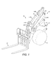
- the material handling machine is a loading shovel machine having a front part 12 which is articulated via a pivot arrangement 14 (only part of which is shown) to a rear part (not shown).
- the rear part includes an operator cab, an engine and rear ground engaging wheels.
- the front part 12 includes a front left ground engaging wheel 15 and a front right ground engaging wheel (not shown) which is positioned on the right hand side of the front part 12 opposite the front left ground engaging wheel 15.
- Mounted on front part 12 is an implement manoeuvring apparatus 16 (also known as linkage arrangement) on the front of which can be mounted a materials handling implement 18, in this case a pair of pallet tines.
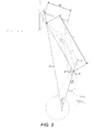
- the apparatus 16 is defined by a set of links interconnected by pivots as will be further described below. As can be seen in figure 2 , the apparatus 16 has a first link L1, a second link L2, a third link L3, a fourth link L4, a fifth link L5 and a support 20.
- the first link is defined by a pair of spaced apart links L1A and L1B.
- the second link defines part of a quick attach structure to which implements, such as pallet tines 18 can be quickly attached and detached.
- the third link is defined by a rod.
- the fourth link is defined by a pair of spaced apart plates L4A and L4B.
- the fifth link is defined by an adjustable link, in this case by a hydraulically actuated ram 22.
- the support 20 is defined by a pair of plates 24A and 24B and by a central plate 25. Plates 24A, 24B and 25 are all secured together to form the support 20.
- the first link is pivotally mounted on the support 20 at a first pivot P1.
- the second link is pivotally mounted relative to the first link at a second pivot P2.
- the third link is pivotally mounted relative to the second link at a third pivot P3.
- the fourth link is pivotally mounted relative to the third link at a fourth pivot P4.
- the fourth link is also pivotally mounted relative to the first link at a fifth pivot P5.
- the fifth link is pivotally mounted to the fourth link at a sixth pivot P6.
- the fifth link is also pivotally mounted on the support at a seventh pivot P7.
- the fifth pivot P5 is located on the first link between the first and second pivots.
- a first line A is defined between the first and second pivots.
- the sixth pivot is located on the fourth link between the fourth and fifth pivots.
- a second line B is defined between the fourth and the fifth pivots.
- the fifth pivot is positioned on a same side of the first line (A) as the fourth pivot.
- the perpendicular distance between the first line A and the fifth pivot is 95.2 mm i.e. 0.057 times L (see below) or 0.131 M (see below).
- the sixth pivot is positioned on a same side of the second line (B) as the seventh pivot.
- the perpendicular distance between the second line B and the sixth pivot is 47.9 mm i.e. 0.029 times L (see below) or 0.066 times M (see below).
- the distance between the first and second pivots is a fixed distance L (see figure 3 ), which in this example is 1655 mm.
- the second, third, fourth and fifth pivots together form a quadrilateral in which all internal angles are less than 180°.
- the first, fifth, sixth and seventh pivots together form quadrilateral in which all internal angles are less than 180°.
- the seventh pivot P7 is positioned higher than the first pivot P1.
- a lift ram 28 is pivotally mounted at one end to the support 20 at pivot P8 and is pivotally mounted to the first link L1 at pivot P9.
- a further lift ram 29 is mounted on the right hand side of link L1B and is similarly pivotally mounted to the support and to the first link.
- the lift rams 28 and 29 can be operated so as to extend, thereby causing the material handling implement 18 to be lifted, for example to the position shown in figure 3 or any intermediate position.
- the material handling implement 18 can be lowered from figure 3 position to the figure 1 position or any intermediate position by contracting the lift rams 28 and 29.
- Figure 2 shows the implement manoeuvring apparatus 16 in a lowered position. In this position a line C drawn between the first and seventh pivots intersects a line D drawn between the second and third pivots at an angle E, which is 27.55°. As shown in figure 2 the angle F between lines A and C is 21.24°.
- an analysis of the geometry shows that when moving from the figure 2 position to the figure 3 position (whilst maintaining the length of the fifth link the same, i.e. whilst not extending or reducing the length of the ram 22) the second link (and hence the pallet tines 18) do not "dump" i.e. tip forwards or rotate anticlockwise during any part of the movement from the figure 2 position to the figure 3 position.
- the linkage arrangement 16 has been designed to lift the pallet tines (and hence any pallet mounted thereon) substantially parallel to the ground. This reduces the risk of a pallet or a load on a pallet falling. It also results in faster loadings/unloading since the pallet tines remain substantially parallel to the ground at all positions during lift, this means that the pallet tines will remain substantially parallel to the ground at whatever height a pallet is picked up from, and will also remain parallel to the ground at whatever height a pallet is deposited at.
- FIG 5 A comparison between figure 5 and figure 2 shows that in figure 5 the fifth link L5 has been shortened when compared to figure 2 .
- the length of the fifth link in the figure 5 and figure 6 position is 1088.3 mm i.e. 0.658 times L.
- the shovel In figure 5 the shovel is fully “crowded" and the angle E" between lines C and D is 12.02°. In figure 5 the angle F" is 21.24°.
- Figure 6 shows the shovel 19 in a fully raised position wherein angle E'" is 12.86° and angle F'" is 132.72°.
- angle E' is 12.86°
- angle F' is 132.72°.
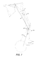
- FIG. 7 shows that the first link L1 is in the same position as shown in figure 6 .
- the ram 22 has been extended so as to rotate the fourth link anticlockwise. This in turn has caused the third link to move to the left when viewing the drawings resulting in the bucket rotating anticlockwise about the second pivot, i.e. rotating in a dump direction.
- the distances between various pivots have been shown as a proportion of the largest distance between any two pivots.
- the largest distance between any two pivots is the distance between the first and second pivots and this distance is defined as distance L. Consequently, for example the distance between, say, the first and fifth pivots can be described as 0.712 L.
- the "master" pivot distance is the distance L between the first and second pivots.
- An alternative analysis can be carried out by choosing a different "master" pivot distance, i.e. a distance between a different pair of pivots.
- the following analysis uses the distance between the third and fourth pivots as the "master" pivot distance.
- the distance between the third and fourth pivots is a fixed distance M (see figure 3 ), which (as mentioned above) is 725 mm.
- the length of the fifth link is (as mentioned above) 1,125 mm i.e. 1.552 M.
- the length of the fifth link is (as mentioned above) 1.088.3 mm, i.e. 1.501 M.
- the first link L1 can be replaced with a longer link having dimensions as follows:-
- the fifth pivot is positioned on a same side of the first line (A) as the fourth pivot.
- the perpendicular distance between the first line A and the fifth pivot is 106 mm i.e. 0.146 times M.
Landscapes
- Engineering & Computer Science (AREA)
- Mechanical Engineering (AREA)
- Structural Engineering (AREA)
- Civil Engineering (AREA)
- Transportation (AREA)
- General Engineering & Computer Science (AREA)
- Mining & Mineral Resources (AREA)
- Life Sciences & Earth Sciences (AREA)
- Geology (AREA)
- Forklifts And Lifting Vehicles (AREA)
- Carbon Steel Or Casting Steel Manufacturing (AREA)
- Earth Drilling (AREA)
- Jib Cranes (AREA)
Abstract
Description
- The present invention relates to a material handling machine including an implement manoeuvring apparatus.
- The material handling machines are known in particular loading shovel machines. Such loading shovel machines include a material handling implement in the form of a shovel. The shovel is mounted on a linkage mechanism connected to the chassis or other part of the loading shovel machine. The linkage mechanism is operable by hydraulic rams to lift and lower the shovel. The linkage mechanism is also capable of "dumping" the shovel relative to the machine, i.e. tipping the shovel forwards such that loose material contained therein falls out. Additionally the linkage mechanism is capable of "crowding" the shovel, i.e. tipping the shovel backwards so that loose material can be held within the shovel. Typically the shovel will be crowded as the vehicle is being driven into a pile of loose material to be moved. The combination of driving the vehicle into the pile whilst simultaneously crowding the shovel causes the shovel to fill with material. Once this step has been completed, the shovel will be fully crowded and also full of material. However, it will be at a relatively low position, i.e. close to the ground. It is often necessary to load the loose material into a hopper, truck body, or other container at a high level and accordingly the linkage mechanism is operable to lift the shovel from at or near ground position to a higher position. In prior art linkage mechanisms, as the shovel is being lifted the linkage mechanism is such that the shovel tends to tip either forwards or backwards during the lifting operation and this causes some loose material to fall out of the shovel. Dropping of loose material from the shovel during lifting is clearly inefficient.
- In prior art machines it is possible to change a shovel for another implement, such as a pair of pallet tines. Under these circumstances, the pallet tines will be arranged horizontally as they are inserted under a pallet for example which may be standing on the ground. Similarly, it is often necessary to lift the pallet to a position significantly above the ground. Prior art linkage mechanisms tend to tip the tines either forwards (in a dump direction) or backwards (in a crowd direction) as the pallet is lifted. Under some circumstances this many cause the pallet to slide off the pallet tines or the load to slide the pallet. Under other circumstances as the pallet is placed at a high level, the pallet tines are no longer horizontal with the ground, and hence they can be difficult to extract from within the pallet. This tends to increase loading/unloading time of the pallets which is therefore inefficient.
- There is therefore a need for an improved linkage mechanism which dumps and/or crowds an implement mounted thereon less as the implement is lifted when compared to the prior art.
- Thus, according to the present invention there is provided a material handling machine as defined in the accompanying claims.
- The invention will now be described by way of example only with reference to the accompanying drawings in which:-
-
Figure 1 is an isometric view of part of a material handling machine according to the present invention, -
Figure 2 is a side view offigure 1 with the lifting tines in a lowered position, -
Figure 3 is a side view offigure 1 with the lifting tines in a raised position, -
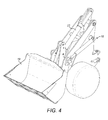
Figure 4 shows the material handling machine offigure 1 fitted with a shovel, -
Figure 5 is a side view offigure 4 with the shovel in a lowered crowded position, -
Figure 6 is a side view offigure 4 with the shovel in a raised crowded position, and -
Figure 7 is a side view offigure 4 with the shovel in a raised dumped position. - With reference to the figures there is shown a
material handling machine 10, only part of which is shown. In this case the material handling machine is a loading shovel machine having afront part 12 which is articulated via a pivot arrangement 14 (only part of which is shown) to a rear part (not shown). The rear part includes an operator cab, an engine and rear ground engaging wheels. Thefront part 12 includes a front left groundengaging wheel 15 and a front right ground engaging wheel (not shown) which is positioned on the right hand side of thefront part 12 opposite the front left groundengaging wheel 15. Mounted onfront part 12 is an implement manoeuvring apparatus 16 (also known as linkage arrangement) on the front of which can be mounted a materials handling implement 18, in this case a pair of pallet tines. Theapparatus 16 is defined by a set of links interconnected by pivots as will be further described below. As can be seen infigure 2 , theapparatus 16 has a first link L1, a second link L2, a third link L3, a fourth link L4, a fifth link L5 and asupport 20. - The first link is defined by a pair of spaced apart links L1A and L1B. The second link defines part of a quick attach structure to which implements, such as
pallet tines 18 can be quickly attached and detached. The third link is defined by a rod. The fourth link is defined by a pair of spaced apart plates L4A and L4B. The fifth link is defined by an adjustable link, in this case by a hydraulically actuatedram 22. Thesupport 20 is defined by a pair ofplates central plate 25.Plates support 20. - The first link is pivotally mounted on the
support 20 at a first pivot P1. The second link is pivotally mounted relative to the first link at a second pivot P2. The third link is pivotally mounted relative to the second link at a third pivot P3. The fourth link is pivotally mounted relative to the third link at a fourth pivot P4. The fourth link is also pivotally mounted relative to the first link at a fifth pivot P5. The fifth link is pivotally mounted to the fourth link at a sixth pivot P6. The fifth link is also pivotally mounted on the support at a seventh pivot P7. - The fifth pivot P5 is located on the first link between the first and second pivots. A first line A is defined between the first and second pivots.
- The sixth pivot is located on the fourth link between the fourth and fifth pivots. A second line B is defined between the fourth and the fifth pivots.
- The fifth pivot is positioned on a same side of the first line (A) as the fourth pivot. The perpendicular distance between the first line A and the fifth pivot is 95.2 mm i.e. 0.057 times L (see below) or 0.131 M (see below).
- The sixth pivot is positioned on a same side of the second line (B) as the seventh pivot. The perpendicular distance between the second line B and the sixth pivot is 47.9 mm i.e. 0.029 times L (see below) or 0.066 times M (see below).
- The distance between the first and second pivots is a fixed distance L (see
figure 3 ), which in this example is 1655 mm. - The distance between certain other pivots is a fixed percentage of the distance between the first and second pivots, thus:-
- the distance between the first and fifth pivots is 1178.8 mm i.e. 0.712 times L
- the distance between the second and fifth pivots is 489.3 mm i.e. 0.296 times L
- the distance between the second and third pivots is 303 mm i.e. 0.183 times L
- the distance between the third and fourth pivots is 725 mm i.e. 0.438 times L
- the distance between the fourth and sixth pivots is 212.9 mm i.e. 0.129 times L
- the distance between the fifth and sixth pivots is 318 mm i.e. 0.192 times L
- the distance between the first and seventh pivots is 230 mm i.e. 0.139 times L
- The second, third, fourth and fifth pivots together form a quadrilateral in which all internal angles are less than 180°. The first, fifth, sixth and seventh pivots together form quadrilateral in which all internal angles are less than 180°. The seventh pivot P7 is positioned higher than the first pivot P1.
- A
lift ram 28 is pivotally mounted at one end to thesupport 20 at pivot P8 and is pivotally mounted to the first link L1 at pivot P9. A further lift ram 29 is mounted on the right hand side of link L1B and is similarly pivotally mounted to the support and to the first link. The lift rams 28 and 29 can be operated so as to extend, thereby causing the material handling implement 18 to be lifted, for example to the position shown infigure 3 or any intermediate position. The material handling implement 18 can be lowered fromfigure 3 position to thefigure 1 position or any intermediate position by contracting the lift rams 28 and 29. -
Figure 2 shows the implementmanoeuvring apparatus 16 in a lowered position. In this position a line C drawn between the first and seventh pivots intersects a line D drawn between the second and third pivots at an angle E, which is 27.55°. As shown infigure 2 the angle F between lines A and C is 21.24°. - As shown in
figure 3 , in the raised position lines C and D intersect at angle E', which is 25.95°, this being less than 4° less than angle E as shown onfigure 2 . In other words when moving from thefigure 2 position to thefigure 3 position, thepallet tines 18 have "crowded" i.e. tipped backwards (rotated clockwise when viewing the figures) less than 4 degrees. In both thefigure 2 andfigure 3 position the length of the fifth link L5 is the same, i.e. in bothfigure 2 andfigure 3 position theram 22 had not been extended or contracted. As shown infigures 2 and3 the length of the fifth link is 1125 mm i.e. 0.680 times L. - Furthermore, an analysis of the geometry shows that when moving from the
figure 2 position to thefigure 3 position (whilst maintaining the length of the fifth link the same, i.e. whilst not extending or reducing the length of the ram 22) the second link (and hence the pallet tines 18) do not "dump" i.e. tip forwards or rotate anticlockwise during any part of the movement from thefigure 2 position to thefigure 3 position. - As will be appreciated, the
linkage arrangement 16 has been designed to lift the pallet tines (and hence any pallet mounted thereon) substantially parallel to the ground. This reduces the risk of a pallet or a load on a pallet falling. It also results in faster loadings/unloading since the pallet tines remain substantially parallel to the ground at all positions during lift, this means that the pallet tines will remain substantially parallel to the ground at whatever height a pallet is picked up from, and will also remain parallel to the ground at whatever height a pallet is deposited at. This in turn means that the material handling operator does not need to adjust the angle of the pallet by lengthening or shortening the ram 22 (the fifth link) in order to ensure the tines can be driven under the pallet when picking up the pallet or withdrawn from under the pallet when having just deposited a pallet. This results in faster operation. With reference tofigures 4 to 7 there is shown thematerial handling machine 10 offigure 1 . In this case thepallet tines 18 have been removed and replaced with ashovel 19. This is a relatively simple task for the operator to achieve since the second link 2 has a "quick hitch" attachment onto which can be mounted either thepallet tines 18 or theshovel 19. - A comparison between
figure 5 andfigure 2 shows that infigure 5 the fifth link L5 has been shortened when compared tofigure 2 . The length of the fifth link in thefigure 5 andfigure 6 position is 1088.3 mm i.e. 0.658 times L. Infigure 5 the shovel is fully "crowded" and the angle E" between lines C and D is 12.02°. Infigure 5 the angle F" is 21.24°. -
Figure 6 shows theshovel 19 in a fully raised position wherein angle E'" is 12.86° and angle F'" is 132.72°. As will be appreciated, in moving from thefigure 5 position to thefigure 6 position theshovel 19 has dumped by only 0.8°, i.e. less than 1°. - Furthermore, an analysis of the geometry shows that when moving from the
figure 5 position to thefigure 6 position the second link, and hence thebucket 19 does not "dump" i.e. tip forwards by more than 3.5° and it does not "crowd" i.e. tip backwards by more than 0.2°. Accordingly, in moving from thefigure 5 position to thefigure 6 position the angle of the bucket remains substantially the same and therefore less loose material and the like will be spilled from the bucket during the lift than when compared with the prior art. - Consideration of
figure 7 shows that the first link L1 is in the same position as shown infigure 6 . However, infigure 7 theram 22 has been extended so as to rotate the fourth link anticlockwise. This in turn has caused the third link to move to the left when viewing the drawings resulting in the bucket rotating anticlockwise about the second pivot, i.e. rotating in a dump direction. - In the above analysis, the distances between various pivots have been shown as a proportion of the largest distance between any two pivots. Thus, the largest distance between any two pivots is the distance between the first and second pivots and this distance is defined as distance L. Consequently, for example the distance between, say, the first and fifth pivots can be described as 0.712 L. In this analysis the "master" pivot distance is the distance L between the first and second pivots.
- An alternative analysis can be carried out by choosing a different "master" pivot distance, i.e. a distance between a different pair of pivots.
- The following analysis uses the distance between the third and fourth pivots as the "master" pivot distance.
- The distance between the third and fourth pivots is a fixed distance M (see
figure 3 ), which (as mentioned above) is 725 mm. - The distance between certain other pivots is a fixed percentage of the distance between the third and fourth pivots, thus:-
- the distance between the first and second pivots is (as mentioned above) 1655 mm, i.e. 2.283 times M
- the distance between the first and fifth pivots is (as mentioned above) 1178.8 mm, i.e. 1.626 times M
- the distance between the second and fifth pivots is (as mentioned above) 489.3 mm, i.e. 0.675 times M
- the distance between the second and third pivots is (as mentioned above) 303 mm, i.e. 0.418 times M
- the distance between the fourth and sixth pivots is (as mentioned above) 212.9 mm, i.e. 0.294 times M
- the distance between the fifth and sixth pivots is (as mentioned above) 318 mm, i.e. 0.439 times M
- the distance between the first and seventh pivots is (as mentioned above) 230 mm, i.e. 0.317 times M
- As shown in
figures 2 and3 the length of the fifth link is (as mentioned above) 1,125 mm i.e. 1.552 M. - As shown in
figures 5 and6 the length of the fifth link is (as mentioned above) 1.088.3 mm, i.e. 1.501 M. - In a second embodiment (not shown) the first link L1 can be replaced with a longer link having dimensions as follows:-
- the distance between the first and second pivots is 1890 mm i.e. 2.607 M
- the distance between the first and fifth pivots is 1425 mm i.e. 1.966 M
- the distance between the second and fifth pivots is 481 mm i.e. 0.663 M
- The fifth pivot is positioned on a same side of the first line (A) as the fourth pivot. The perpendicular distance between the first line A and the fifth pivot is 106 mm i.e. 0.146 times M.
- An analysis of the geometry of such an arrangement shows that moving from a lowered position (the equivalent of the
figure 2 position) where the first line A is angled by 23.24° relative to line C to a raised position (the equivalent of thefigure 3 position) where the first line A is angled by 127.07° relative to line C whilst the distance between the sixth and seventh pivots remains at 1350.35 mm (i.e. 1.863 M) results in the second link crowding by less than 2° e.g. less than 4° between the lowered and raised positions. At every intermediate position the second link has not dumped. At every intermediate position the second link has crowded by less than 2° e.g. has crowded by less than 4°. - An analysis of the geometry of such an arrangement shows that moving from a lowered position (the equivalent of the
figure 5 position) where the first line A is angled by 23.24° relative to line C and a raised position (the equivalent of thefigure 6 position) where the first line A is angled by 127.07° relative to line C whilst the distance between the sixth and seventh pivots remains at 1,326 mm, i.e. 1.829 M results in the second link crowding by less than 0.5° e.g. less than 1° between the lowered and raised positions. At every intermediate position the second link has not dumped by more than 2.5° e.g. has not dumped by more than 3.5°. At every intermediate position the second link has not crowded by more than 0.5° e.g. has not crowded by more than 4°.
Claims (13)
- A material handling machine including an implement manoeuvring apparatus, the implement manoeuvring apparatus including
a support,
a first link,
a second link,
a third link,
a fourth link and
a fifth link,
the first link being pivotally mounted relative to the support at a first pivot,
the second link being pivotally mounted relative to the first link at a second pivot,
the third link being pivotally mounted relative to the second link at a third pivot, the fourth link being pivotally mounted relative to the third link at a fourth pivot, the fourth link being pivotally mounted relative to the first link at a fifth pivot, the fifth link being pivotally mounted relative to the fourth link at a sixth pivot, the fifth link being pivotally mounted relative to the support at a seventh pivot, the fifth pivot being located on the first link between the first and second pivots, the sixth pivot being located on the fourth link between the fourth and fifth pivots,
a distance between the third and fourth pivots being a fixed distance M,
a distance between the first and second pivots being a fixed distance,
a distance between the first and fifth pivots being a fixed distance,
a distance between the second and fifth pivots being a fixed distance,
a distance between the second and third pivots being a fixed distance 0.418 M ± 2%,
a distance between the fourth and sixth pivots being a fixed distance 0.294 M ± 2%,
a distance between the fifth and sixth pivots being a fixed distance 0.439 M ± 2%,
a distance between the first and seventh pivots being a fixed distance 0.317 M ± 2%,
a distance between the sixth and seventh pivots being capable of being varied,
a first line (A) being defined between the first and second pivots, the fifth pivot being positioned on a same side of the first line (A) as the fourth pivot,
a second line (B) being defined between the fourth and fifth pivots, the sixth pivot being positioned on a same side of the second line (B) as the seventh pivot, a perpendicular distance between the second line and the sixth pivot is 0.066 M ± 10%,
the second, third, fourth and fifth pivots forming a quadrilateral in which all internal angles are less than 180°,
the first, fifth, sixth and seventh pivots forming a quadrilateral in which all internal angles are less than 180°,
the seventh pivot being positioned higher than the first pivot,
the mechanism having:a first position where the first line (A) is angled by 24° (F) relative to a line (C) drawn between the first and seventh pivots, and the distance between the sixth and seventh pivots is a first distance and a line (C) drawn between the first and seventh pivots is angled at a first angle (E) relative to a line drawn between the second and third pivots, anda second position where the first line (A) is angled by 127° (F') relative to the line (C) drawn between the first and seventh pivots, and the distance between the sixth and seventh pivots is said first distance and wherein the second link has crowded less than 4° relative to the first angle of the second link. - A material handling machine as defined in claim 1 wherein the apparatus has a plurality of intermediate positions between the first position and the second position and at every intermediate position the distance between the sixth pivot and the seventh pivot is said first distance and the second link has not dumped relative to the first angle.
- A material handling machine as defined in claim 2 wherein at every intermediate position the second link has not crowded by more than 4° relative to the first angle.
- A material handling machine including an implement manoeuvring apparatus, the implement manoeuvring apparatus including:a support,a first link,a second link,a third link,a fourth link anda fifth link,the first link being pivotally mounted relative to the support at a first pivot,the second link being pivotally mounted relative to the first link at a second pivot,the third link being pivotally mounted relative to the second link at a third pivot,the fourth link being pivotally mounted relative to the third link at a fourth pivot,the fourth link being pivotally mounted relative to the first link at a fifth pivot,the fifth link being pivotally mounted relative to the fourth link at a sixth pivot,the fifth link being pivotally mounted relative to the support at a seventh pivot,the fifth pivot being located on the first link between the first and second pivots,the sixth pivot being located on the fourth link between the fourth and fifth pivots,a distance between the third and fourth pivots being a fixed distance M,a distance between the first and second pivots being a fixed distance,a distance between the first and fifth pivots being a fixed distance,a distance between the second and fifth pivots being a fixed distance,a distance between the second and third pivots being a fixed distance 0.418 M ± 2%,a distance between the fourth and sixth pivots being a fixed distance 0.294 M ± 2%,a distance between the fifth and sixth pivots being a fixed distance 0.439 M ± 2%,a distance between the first and seventh pivots being a fixed distance 0.317 M ± 2%,a distance between the sixth and seventh pivots being capable of being varied,a first line (A) being defined between the first and second pivots, the fifth pivot being positioned on a same side of the first line (A) as the fourth pivot,a second line (B) being defined between the fourth and fifth pivots, the sixth pivot being positioned on a same side of the second line (B) as the seventh pivot, a perpendicular distance between the second line and the sixth pivot is 0.066 M ± 10%,the second, third, fourth and fifth pivots forming a quadrilateral in which all internal angles are less than 180°,the first, fifth, sixth and seventh pivots forming a quadrilateral in which all internal angles are less than 180°,the seventh pivot being positioned higher than the first pivot,the mechanism having:a first position where the first line (A) is angled by 24° (F") relative to a line (C) drawn between the first and seventh pivots, and the distance between the sixth and seventh pivots is a second distance and a line (C) drawn between the first and seventh pivots is angled at a first angle (E) relative to a line drawn between the second and third pivots, anda second position where the first line (A) is angled by 127° (F"') relative to the line (C) drawn between the first and seventh pivots, and the distance between the sixth and seventh pivots is said second distance and wherein the second link has dumped less than 1° relative to the first angle of the second link, and/or has crowded less than 0.5° relative to the first angle of the second link.
- A material handling machine as defined in claim 4 wherein the apparatus has a plurality of intermediate positions between the first position and the second position and at every intermediate position the distance between the sixth pivot and the seventh pivot is said second distance and the second link has not dumped by more than 3.5° relative to the first angle.
- A material handling machine as defined in claim 5 wherein at every intermediate position the second link has not crowded by more than 0.5° relative to the first angle.
- A material handling machine as defined in claim 1 or 4 wherein:- the distance between the first and second pivots is between 2.283 M ± 0.3% and 2.607 M ± 0.3%, and/or
the distance between the first and fifth pivots is between 1.626 M ± 0.4% and 1.965 M ± 0.4%, and/or
the distance between the second and fifth pivots is between 0.675 M ± 1.0% and 0.663 M ± 1.0%, and/or
a perpendicular distance between the first line (A) and the fifth pivot is between 0.131 M ± 5% and 0.146 M ± 5%. - A material handling machine as defined in claim 1 or 4 wherein:- the distance between the first and second pivots is 2.283 M ± 0.3%, and/or
the distance between the first and fifth pivots is 1.626 M ± 0.4%, and/or
the distance between the second and fifth pivots is 0.675 M ± 1.0%, and/or
a perpendicular distance between the first line (A) and the fifth pivot is 0.131 M ± 5%. - A material handling machine as defined in claim 1 or 8 wherein the first distance is 1.552 M.
- A material handling machine as defined in claim 1 or 8 when dependent upon claim 4 wherein the second distance is 1.501 M.
- A material handling machine as defined in claim 1 or 4 wherein:- the distance between the first and second pivots is 2.607 M ± 0.3%, and/or
the distance between the first and fifth pivots is 1.965 M ± 0.4%, and/or
the distance between the second and fifth pivots is 0.663 M ± 1.0%, and/or
a perpendicular distance between the first line (A) and the fifth pivot is 0.146 M ± 5%. - A material handling machine as defined in claim 1 or 11 wherein the first distance is 1.863 M.
- A material handling machine as defined in claim 1 or 11 when dependent upon claim 4 wherein the second distance is 1.829 M.
Applications Claiming Priority (1)
| Application Number | Priority Date | Filing Date | Title |
|---|---|---|---|
| GB1319211.7A GB2519799B (en) | 2013-10-31 | 2013-10-31 | Material handling machine |
Publications (3)
| Publication Number | Publication Date |
|---|---|
| EP2868619A1 true EP2868619A1 (en) | 2015-05-06 |
| EP2868619B1 EP2868619B1 (en) | 2017-11-29 |
| EP2868619B8 EP2868619B8 (en) | 2021-10-27 |
Family
ID=49767439
Family Applications (1)
| Application Number | Title | Priority Date | Filing Date |
|---|---|---|---|
| EP14190435.9A Active EP2868619B8 (en) | 2013-10-31 | 2014-10-27 | Material handling machine |
Country Status (4)
| Country | Link |
|---|---|
| EP (1) | EP2868619B8 (en) |
| CN (2) | CN204265013U (en) |
| AU (1) | AU2014256379B2 (en) |
| GB (1) | GB2519799B (en) |
Families Citing this family (4)
| Publication number | Priority date | Publication date | Assignee | Title |
|---|---|---|---|---|
| GB2519799B (en) * | 2013-10-31 | 2018-04-25 | Jc Bamford Excavators Ltd | Material handling machine |
| CN109867148B (en) * | 2019-03-05 | 2020-05-01 | 项赛赛 | A charging device used in the field of housing construction |
| CN112079294B (en) * | 2020-09-25 | 2022-02-15 | 山河智能装备股份有限公司 | Cargo handling device and cargo handling car |
| CN112193137B (en) * | 2020-10-10 | 2022-04-01 | 北京航天发射技术研究所 | Cabin synchronous retraction device |
Citations (2)
| Publication number | Priority date | Publication date | Assignee | Title |
|---|---|---|---|---|
| WO1999001620A1 (en) * | 1997-06-30 | 1999-01-14 | Caterpillar Commercial S.A.R.L. | Tilt linkage arrangement |
| EP0957208A2 (en) * | 1998-05-12 | 1999-11-17 | FKI Fai Komatsu Industries S.p.A. | Shovel arm for earth-moving vehicles |
Family Cites Families (6)
| Publication number | Priority date | Publication date | Assignee | Title |
|---|---|---|---|---|
| US3155253A (en) * | 1963-06-21 | 1964-11-03 | John S Pilch | Control system for tractor mounted apparatus |
| US3487958A (en) * | 1968-01-31 | 1970-01-06 | Caterpillar Tractor Co | Self-cycling loader |
| US5964301A (en) * | 1998-08-12 | 1999-10-12 | Glasgow; Kenny Ern | Tilting loader bucket mechanism |
| CN2543910Y (en) * | 2002-02-10 | 2003-04-09 | 张志远 | Raking unloading type loading/unloading machine |
| JP4956008B2 (en) * | 2006-01-13 | 2012-06-20 | 株式会社小松製作所 | Work machine |
| GB2519799B (en) * | 2013-10-31 | 2018-04-25 | Jc Bamford Excavators Ltd | Material handling machine |
-
2013
- 2013-10-31 GB GB1319211.7A patent/GB2519799B/en active Active
-
2014
- 2014-10-27 EP EP14190435.9A patent/EP2868619B8/en active Active
- 2014-10-30 AU AU2014256379A patent/AU2014256379B2/en not_active Ceased
- 2014-10-31 CN CN201420642969.4U patent/CN204265013U/en not_active Withdrawn - After Issue
- 2014-10-31 CN CN201410602262.5A patent/CN104590907B/en not_active Expired - Fee Related
Patent Citations (2)
| Publication number | Priority date | Publication date | Assignee | Title |
|---|---|---|---|---|
| WO1999001620A1 (en) * | 1997-06-30 | 1999-01-14 | Caterpillar Commercial S.A.R.L. | Tilt linkage arrangement |
| EP0957208A2 (en) * | 1998-05-12 | 1999-11-17 | FKI Fai Komatsu Industries S.p.A. | Shovel arm for earth-moving vehicles |
Also Published As
| Publication number | Publication date |
|---|---|
| CN104590907B (en) | 2018-12-14 |
| EP2868619B8 (en) | 2021-10-27 |
| CN204265013U (en) | 2015-04-15 |
| GB201319211D0 (en) | 2013-12-18 |
| CN104590907A (en) | 2015-05-06 |
| AU2014256379A1 (en) | 2015-05-14 |
| GB2519799B (en) | 2018-04-25 |
| AU2014256379B2 (en) | 2017-10-26 |
| EP2868619B1 (en) | 2017-11-29 |
| GB2519799A (en) | 2015-05-06 |
Similar Documents
| Publication | Publication Date | Title |
|---|---|---|
| US4952111A (en) | Pick up and stacking device for large hay bales | |
| CN103328730B (en) | Improved reverse linkage mechanism for wheel loaders | |
| EP2868619B1 (en) | Material handling machine | |
| US3152706A (en) | Grapple device | |
| US7887275B2 (en) | Bale handling vehicle | |
| EP3116748B1 (en) | Self-propelled utility vehicle having a trough | |
| US20150289449A1 (en) | Bale Handler | |
| CN106275116B (en) | Crawler-type multifunctional agriculture and forestry equipment | |
| US2870925A (en) | Apparatus for stocking small logs and picking up same from a stock for loading vehicles | |
| DE202014004566U1 (en) | Lifting device for coupling to the changing devices of Hofladern, front loaders and three-point linkage to increase the lifting height of the implements | |
| US3348715A (en) | Vehicle with bucket | |
| EP2774811B1 (en) | Vehicle with a pivoting loading surface | |
| CN101102918A (en) | container loading equipment | |
| US20140119869A1 (en) | Bucket Design for Maximizing Liquid Transport | |
| US3235983A (en) | Earth moving apparatus | |
| DE19800164A1 (en) | Mobile loading machine with front loading equipment | |
| US2755944A (en) | Loader devices on tractors | |
| DE1961969A1 (en) | Loading shovel for a shovel loader or the like. | |
| EP2647280A1 (en) | Bale lifting device and method for lifting a bale | |
| US3175711A (en) | Tractor loaders | |
| CN223534451U (en) | A loader | |
| AT408498B (en) | Transfer device on cutter loaders | |
| KR20150062765A (en) | The fork lift truck of the self loading and dump | |
| CN104609341A (en) | Self-loading and self-unloading device for forklift | |
| US20020154969A1 (en) | Bale lifter |
Legal Events
| Date | Code | Title | Description |
|---|---|---|---|
| PUAI | Public reference made under article 153(3) epc to a published international application that has entered the european phase |
Free format text: ORIGINAL CODE: 0009012 |
|
| 17P | Request for examination filed |
Effective date: 20141027 |
|
| AK | Designated contracting states |
Kind code of ref document: A1 Designated state(s): AL AT BE BG CH CY CZ DE DK EE ES FI FR GB GR HR HU IE IS IT LI LT LU LV MC MK MT NL NO PL PT RO RS SE SI SK SM TR |
|
| AX | Request for extension of the european patent |
Extension state: BA ME |
|
| R17P | Request for examination filed (corrected) |
Effective date: 20151028 |
|
| RBV | Designated contracting states (corrected) |
Designated state(s): AL AT BE BG CH CY CZ DE DK EE ES FI FR GB GR HR HU IE IS IT LI LT LU LV MC MK MT NL NO PL PT RO RS SE SI SK SM TR |
|
| RIC1 | Information provided on ipc code assigned before grant |
Ipc: E02F 3/34 20060101ALI20170407BHEP Ipc: B66F 9/065 20060101AFI20170407BHEP Ipc: E02F 3/28 20060101ALI20170407BHEP |
|
| GRAP | Despatch of communication of intention to grant a patent |
Free format text: ORIGINAL CODE: EPIDOSNIGR1 |
|
| STAA | Information on the status of an ep patent application or granted ep patent |
Free format text: STATUS: GRANT OF PATENT IS INTENDED |
|
| INTG | Intention to grant announced |
Effective date: 20170530 |
|
| GRAS | Grant fee paid |
Free format text: ORIGINAL CODE: EPIDOSNIGR3 |
|
| GRAA | (expected) grant |
Free format text: ORIGINAL CODE: 0009210 |
|
| STAA | Information on the status of an ep patent application or granted ep patent |
Free format text: STATUS: THE PATENT HAS BEEN GRANTED |
|
| AK | Designated contracting states |
Kind code of ref document: B1 Designated state(s): AL AT BE BG CH CY CZ DE DK EE ES FI FR GB GR HR HU IE IS IT LI LT LU LV MC MK MT NL NO PL PT RO RS SE SI SK SM TR |
|
| REG | Reference to a national code |
Ref country code: CH Ref legal event code: EP |
|
| REG | Reference to a national code |
Ref country code: AT Ref legal event code: REF Ref document number: 950183 Country of ref document: AT Kind code of ref document: T Effective date: 20171215 |
|
| REG | Reference to a national code |
Ref country code: IE Ref legal event code: FG4D |
|
| REG | Reference to a national code |
Ref country code: DE Ref legal event code: R096 Ref document number: 602014017827 Country of ref document: DE |
|
| REG | Reference to a national code |
Ref country code: NL Ref legal event code: FP |
|
| REG | Reference to a national code |
Ref country code: LT Ref legal event code: MG4D |
|
| REG | Reference to a national code |
Ref country code: AT Ref legal event code: MK05 Ref document number: 950183 Country of ref document: AT Kind code of ref document: T Effective date: 20171129 |
|
| PG25 | Lapsed in a contracting state [announced via postgrant information from national office to epo] |
Ref country code: NO Free format text: LAPSE BECAUSE OF FAILURE TO SUBMIT A TRANSLATION OF THE DESCRIPTION OR TO PAY THE FEE WITHIN THE PRESCRIBED TIME-LIMIT Effective date: 20180228 Ref country code: LT Free format text: LAPSE BECAUSE OF FAILURE TO SUBMIT A TRANSLATION OF THE DESCRIPTION OR TO PAY THE FEE WITHIN THE PRESCRIBED TIME-LIMIT Effective date: 20171129 Ref country code: FI Free format text: LAPSE BECAUSE OF FAILURE TO SUBMIT A TRANSLATION OF THE DESCRIPTION OR TO PAY THE FEE WITHIN THE PRESCRIBED TIME-LIMIT Effective date: 20171129 Ref country code: SE Free format text: LAPSE BECAUSE OF FAILURE TO SUBMIT A TRANSLATION OF THE DESCRIPTION OR TO PAY THE FEE WITHIN THE PRESCRIBED TIME-LIMIT Effective date: 20171129 Ref country code: ES Free format text: LAPSE BECAUSE OF FAILURE TO SUBMIT A TRANSLATION OF THE DESCRIPTION OR TO PAY THE FEE WITHIN THE PRESCRIBED TIME-LIMIT Effective date: 20171129 |
|
| PG25 | Lapsed in a contracting state [announced via postgrant information from national office to epo] |
Ref country code: HR Free format text: LAPSE BECAUSE OF FAILURE TO SUBMIT A TRANSLATION OF THE DESCRIPTION OR TO PAY THE FEE WITHIN THE PRESCRIBED TIME-LIMIT Effective date: 20171129 Ref country code: GR Free format text: LAPSE BECAUSE OF FAILURE TO SUBMIT A TRANSLATION OF THE DESCRIPTION OR TO PAY THE FEE WITHIN THE PRESCRIBED TIME-LIMIT Effective date: 20180301 Ref country code: AT Free format text: LAPSE BECAUSE OF FAILURE TO SUBMIT A TRANSLATION OF THE DESCRIPTION OR TO PAY THE FEE WITHIN THE PRESCRIBED TIME-LIMIT Effective date: 20171129 Ref country code: RS Free format text: LAPSE BECAUSE OF FAILURE TO SUBMIT A TRANSLATION OF THE DESCRIPTION OR TO PAY THE FEE WITHIN THE PRESCRIBED TIME-LIMIT Effective date: 20171129 Ref country code: BG Free format text: LAPSE BECAUSE OF FAILURE TO SUBMIT A TRANSLATION OF THE DESCRIPTION OR TO PAY THE FEE WITHIN THE PRESCRIBED TIME-LIMIT Effective date: 20180228 Ref country code: LV Free format text: LAPSE BECAUSE OF FAILURE TO SUBMIT A TRANSLATION OF THE DESCRIPTION OR TO PAY THE FEE WITHIN THE PRESCRIBED TIME-LIMIT Effective date: 20171129 |
|
| PG25 | Lapsed in a contracting state [announced via postgrant information from national office to epo] |
Ref country code: SK Free format text: LAPSE BECAUSE OF FAILURE TO SUBMIT A TRANSLATION OF THE DESCRIPTION OR TO PAY THE FEE WITHIN THE PRESCRIBED TIME-LIMIT Effective date: 20171129 Ref country code: CZ Free format text: LAPSE BECAUSE OF FAILURE TO SUBMIT A TRANSLATION OF THE DESCRIPTION OR TO PAY THE FEE WITHIN THE PRESCRIBED TIME-LIMIT Effective date: 20171129 Ref country code: CY Free format text: LAPSE BECAUSE OF FAILURE TO SUBMIT A TRANSLATION OF THE DESCRIPTION OR TO PAY THE FEE WITHIN THE PRESCRIBED TIME-LIMIT Effective date: 20171129 Ref country code: EE Free format text: LAPSE BECAUSE OF FAILURE TO SUBMIT A TRANSLATION OF THE DESCRIPTION OR TO PAY THE FEE WITHIN THE PRESCRIBED TIME-LIMIT Effective date: 20171129 Ref country code: DK Free format text: LAPSE BECAUSE OF FAILURE TO SUBMIT A TRANSLATION OF THE DESCRIPTION OR TO PAY THE FEE WITHIN THE PRESCRIBED TIME-LIMIT Effective date: 20171129 |
|
| REG | Reference to a national code |
Ref country code: DE Ref legal event code: R097 Ref document number: 602014017827 Country of ref document: DE |
|
| PG25 | Lapsed in a contracting state [announced via postgrant information from national office to epo] |
Ref country code: PL Free format text: LAPSE BECAUSE OF FAILURE TO SUBMIT A TRANSLATION OF THE DESCRIPTION OR TO PAY THE FEE WITHIN THE PRESCRIBED TIME-LIMIT Effective date: 20171129 Ref country code: IT Free format text: LAPSE BECAUSE OF FAILURE TO SUBMIT A TRANSLATION OF THE DESCRIPTION OR TO PAY THE FEE WITHIN THE PRESCRIBED TIME-LIMIT Effective date: 20171129 Ref country code: SM Free format text: LAPSE BECAUSE OF FAILURE TO SUBMIT A TRANSLATION OF THE DESCRIPTION OR TO PAY THE FEE WITHIN THE PRESCRIBED TIME-LIMIT Effective date: 20171129 Ref country code: RO Free format text: LAPSE BECAUSE OF FAILURE TO SUBMIT A TRANSLATION OF THE DESCRIPTION OR TO PAY THE FEE WITHIN THE PRESCRIBED TIME-LIMIT Effective date: 20171129 |
|
| PLBE | No opposition filed within time limit |
Free format text: ORIGINAL CODE: 0009261 |
|
| STAA | Information on the status of an ep patent application or granted ep patent |
Free format text: STATUS: NO OPPOSITION FILED WITHIN TIME LIMIT |
|
| 26N | No opposition filed |
Effective date: 20180830 |
|
| PG25 | Lapsed in a contracting state [announced via postgrant information from national office to epo] |
Ref country code: SI Free format text: LAPSE BECAUSE OF FAILURE TO SUBMIT A TRANSLATION OF THE DESCRIPTION OR TO PAY THE FEE WITHIN THE PRESCRIBED TIME-LIMIT Effective date: 20171129 |
|
| REG | Reference to a national code |
Ref country code: CH Ref legal event code: PL |
|
| REG | Reference to a national code |
Ref country code: BE Ref legal event code: MM Effective date: 20181031 |
|
| PG25 | Lapsed in a contracting state [announced via postgrant information from national office to epo] |
Ref country code: LU Free format text: LAPSE BECAUSE OF NON-PAYMENT OF DUE FEES Effective date: 20181027 Ref country code: MC Free format text: LAPSE BECAUSE OF FAILURE TO SUBMIT A TRANSLATION OF THE DESCRIPTION OR TO PAY THE FEE WITHIN THE PRESCRIBED TIME-LIMIT Effective date: 20171129 |
|
| REG | Reference to a national code |
Ref country code: IE Ref legal event code: MM4A |
|
| PG25 | Lapsed in a contracting state [announced via postgrant information from national office to epo] |
Ref country code: CH Free format text: LAPSE BECAUSE OF NON-PAYMENT OF DUE FEES Effective date: 20181031 Ref country code: LI Free format text: LAPSE BECAUSE OF NON-PAYMENT OF DUE FEES Effective date: 20181031 Ref country code: BE Free format text: LAPSE BECAUSE OF NON-PAYMENT OF DUE FEES Effective date: 20181031 Ref country code: FR Free format text: LAPSE BECAUSE OF NON-PAYMENT OF DUE FEES Effective date: 20181031 |
|
| PG25 | Lapsed in a contracting state [announced via postgrant information from national office to epo] |
Ref country code: IE Free format text: LAPSE BECAUSE OF NON-PAYMENT OF DUE FEES Effective date: 20181027 |
|
| PG25 | Lapsed in a contracting state [announced via postgrant information from national office to epo] |
Ref country code: MT Free format text: LAPSE BECAUSE OF NON-PAYMENT OF DUE FEES Effective date: 20181027 |
|
| PG25 | Lapsed in a contracting state [announced via postgrant information from national office to epo] |
Ref country code: TR Free format text: LAPSE BECAUSE OF FAILURE TO SUBMIT A TRANSLATION OF THE DESCRIPTION OR TO PAY THE FEE WITHIN THE PRESCRIBED TIME-LIMIT Effective date: 20171129 |
|
| PG25 | Lapsed in a contracting state [announced via postgrant information from national office to epo] |
Ref country code: PT Free format text: LAPSE BECAUSE OF FAILURE TO SUBMIT A TRANSLATION OF THE DESCRIPTION OR TO PAY THE FEE WITHIN THE PRESCRIBED TIME-LIMIT Effective date: 20171129 |
|
| PG25 | Lapsed in a contracting state [announced via postgrant information from national office to epo] |
Ref country code: HU Free format text: LAPSE BECAUSE OF FAILURE TO SUBMIT A TRANSLATION OF THE DESCRIPTION OR TO PAY THE FEE WITHIN THE PRESCRIBED TIME-LIMIT; INVALID AB INITIO Effective date: 20141027 Ref country code: MK Free format text: LAPSE BECAUSE OF NON-PAYMENT OF DUE FEES Effective date: 20171129 |
|
| PG25 | Lapsed in a contracting state [announced via postgrant information from national office to epo] |
Ref country code: IS Free format text: LAPSE BECAUSE OF FAILURE TO SUBMIT A TRANSLATION OF THE DESCRIPTION OR TO PAY THE FEE WITHIN THE PRESCRIBED TIME-LIMIT Effective date: 20180329 Ref country code: AL Free format text: LAPSE BECAUSE OF FAILURE TO SUBMIT A TRANSLATION OF THE DESCRIPTION OR TO PAY THE FEE WITHIN THE PRESCRIBED TIME-LIMIT Effective date: 20171129 |
|
| GRAT | Correction requested after decision to grant or after decision to maintain patent in amended form |
Free format text: ORIGINAL CODE: EPIDOSNCDEC |
|
| PLAA | Information modified related to event that no opposition was filed |
Free format text: ORIGINAL CODE: 0009299DELT |
|
| PLBE | No opposition filed within time limit |
Free format text: ORIGINAL CODE: 0009261 |
|
| REG | Reference to a national code |
Ref country code: CH Ref legal event code: PK Free format text: BERICHTIGUNG B8 |
|
| R26N | No opposition filed (corrected) |
Effective date: 20180830 |
|
| RAP4 | Party data changed (patent owner data changed or rights of a patent transferred) |
Owner name: J.C. BAMFORD EXCAVATORS LIMITED |
|
| P01 | Opt-out of the competence of the unified patent court (upc) registered |
Free format text: CASE NUMBER: UPC_APP_427045/2023 Effective date: 20230525 |
|
| PGFP | Annual fee paid to national office [announced via postgrant information from national office to epo] |
Ref country code: NL Payment date: 20251021 Year of fee payment: 12 |
|
| PGFP | Annual fee paid to national office [announced via postgrant information from national office to epo] |
Ref country code: DE Payment date: 20251021 Year of fee payment: 12 |
|
| PGFP | Annual fee paid to national office [announced via postgrant information from national office to epo] |
Ref country code: GB Payment date: 20251016 Year of fee payment: 12 |