EP2868523A2 - An attachment structure for supporting and releasably attaching a container, a corresponding support structure, a transport vehicle and a container - Google Patents
An attachment structure for supporting and releasably attaching a container, a corresponding support structure, a transport vehicle and a container Download PDFInfo
- Publication number
- EP2868523A2 EP2868523A2 EP14190711.3A EP14190711A EP2868523A2 EP 2868523 A2 EP2868523 A2 EP 2868523A2 EP 14190711 A EP14190711 A EP 14190711A EP 2868523 A2 EP2868523 A2 EP 2868523A2
- Authority
- EP
- European Patent Office
- Prior art keywords
- container
- attachment structure
- support
- locking
- attachment
- Prior art date
- Legal status (The legal status is an assumption and is not a legal conclusion. Google has not performed a legal analysis and makes no representation as to the accuracy of the status listed.)
- Withdrawn
Links
Images




Classifications
-
- B—PERFORMING OPERATIONS; TRANSPORTING
- B60—VEHICLES IN GENERAL
- B60P—VEHICLES ADAPTED FOR LOAD TRANSPORTATION OR TO TRANSPORT, TO CARRY, OR TO COMPRISE SPECIAL LOADS OR OBJECTS
- B60P7/00—Securing or covering of load on vehicles
- B60P7/06—Securing of load
- B60P7/13—Securing freight containers or forwarding containers on vehicles
-
- B—PERFORMING OPERATIONS; TRANSPORTING
- B60—VEHICLES IN GENERAL
- B60P—VEHICLES ADAPTED FOR LOAD TRANSPORTATION OR TO TRANSPORT, TO CARRY, OR TO COMPRISE SPECIAL LOADS OR OBJECTS
- B60P3/00—Vehicles adapted to transport, to carry or to comprise special loads or objects
- B60P3/42—Vehicles adapted to transport, to carry or to comprise special loads or objects convertible from one use to a different one
-
- B—PERFORMING OPERATIONS; TRANSPORTING
- B60—VEHICLES IN GENERAL
- B60P—VEHICLES ADAPTED FOR LOAD TRANSPORTATION OR TO TRANSPORT, TO CARRY, OR TO COMPRISE SPECIAL LOADS OR OBJECTS
- B60P1/00—Vehicles predominantly for transporting loads and modified to facilitate loading, consolidating the load, or unloading
- B60P1/64—Vehicles predominantly for transporting loads and modified to facilitate loading, consolidating the load, or unloading the load supporting or containing element being readily removable
- B60P1/6418—Vehicles predominantly for transporting loads and modified to facilitate loading, consolidating the load, or unloading the load supporting or containing element being readily removable the load-transporting element being a container or similar
- B60P1/6481—Specially adapted for carrying different numbers of container or containers of different sizes
Definitions
- the present invention relates generally to containers and similar means for accommodating goods to be transported and more specifically to means for releasable attachment of such containers to a transport means, such as trucks, lorries, trailers or railway wagons.
- the invention furthermore relates to the use of such containers and transport means for distributing goods in an environmentally friendly manner, for instance within a city.
- US3363803 describes an attachment structure for supporting and releasably attaching a container, cargo bed or the like to a transport vehicle.
- the attachment structure has two parallel spaced elongated attachment members.
- the elongated attachment members have a downwardly facing support surface for abutting an upwardly directed support surface of a support structure on the transport vehicle.
- the elongated attachment members are provided with a laterally facing guide and engagement surface.
- the containers/swap boxes of the present invention are provided with means for releasable attachment to mating means provided on a transport vehicle, preferably a vehicle of a kind that is particularly friendly to the environment.
- a transport vehicle preferably a vehicle of a kind that is particularly friendly to the environment.
- Such vehicles could for instance be battery-powered distribution vehicles. The advantages of such vehicles are low emission, low noise level, and good battery longevity for short distance distribution.
- a “container” should be interpreted broadly to comprise any means that can accommodate goods to be transported and/or stored. Thus, for instance, an upwardly open box of wood or any other material will also fall within the scope of the term “container” as used in this specification.
- a further advantage of small vehicles is that they are more maneuverable in the city, and are better for traffic safety.
- vehicles that are categorized as environmentally friendly are either electric battery powered or powered by an environmental friendly combustion engine or powered by a combination of an electric battery and an environmental friendly combustion engine.
- the objects of the invention are solved by the provision of containers or similar means that are provided with an attachment structure that is either a separate structure that can be attached to the bottom surface of the container or which is formed as an integral part of the container.
- the attachment structure is designed such that it can be releasably attached and secured to a corresponding support structure that is either a separate structure or an integral structure on a transport vehicle, such as a truck, lorry, trailer or railway wagon.
- the support structure is a separate structure that is designed such that it can be attached to any suitable vehicle despite differences in the construction/chassis frame of the vehicle.
- the support structure is provided with quick lock mechanisms that allow quick and easy locking of the attachment structure to the support structure, and thereby the container to the transport vehicle, upon which the support structure is provided.
- quick lock mechanisms allow for securing and releasing without the use of tools.
- an attachment structure for supporting and releasably attaching a container, cargo bed or the like to a transport vehicle, where the container or cargo bed has a length and a width, and where the attachment structure comprises two parallel spaced elongated attachment/support members that extend along at least most of the length of the container or cargo bed, where the elongated attachment members comprises a downwardly facing support surface for abutting an upwardly directed support surface of a support structure on the transport vehicle, where the elongated attachment members are provided with a laterally facing guide and engagement surface, that is provided with recesses or apertures for entering in a locking engagement with a lock mechanism associated with the transport vehicle.
- a container comprising an attachment structure as described above.
- the attachment structure is a separate entity as described above, but it can alternatively be formed as an integral part of the container.
- a support structure for supporting and securing a container, cargo bed or the like to a transport means, such as a vehicle or railway wagon, where the support structure comprises a plurality of transverse support members for supporting an attachment structure according to the invention as described above and a plurality of locking members provided on respective locking mechanisms for releasable locking of the attachment structure to the support structure.
- transport means such as a truck, lorry, trailer, train wagon etc. for transporting containers
- transport means is provided with a support structure as described above.
- This support structure can either be formed as a separate entity that can be mounted on a transport means on demand or be formed as an integral part of a transport means.
- the invention relates to an assembly of an attachment structure according to the invention and a support structure according to the invention, where the attachment structure is provided with means that are adapted to enter into a locking and releasable engagement with mating means provided on the support structure.
- the invention relates to the use of containers and transport vehicles according to the invention for environmentally friendly transport and distribution of goods for instance in central parts of a city.
- the flexible and versatile containers provided with an attachment structure according to the invention together with transport vehicles provided with support structures according to the invention makes it easy to re-load goods from larger and less environmental friendly vehicles unto transport vehicles/containers according to the invention and distribute the good for instance within a central part of a city, where transport using larger and less environmental friendly vehicles would be problematic.
- attachment structures, containers, support structures and transport vehicles are given, but it is understood that these embodiments only constitute non-limiting examples of how the present invention can be implemented in practice. Also, a practical example of using these various means fro environmental friendly transport of goods is given.
- FIG. 1 With reference to figure 1 there is shown a schematic perspective representation of a container according to a first example embodiment of the invention.
- the container is generally indicated by reference numeral 1 and is provided with an attachment structure 2 at the bottom surface of the container.
- an attachment structure 2 Extending longitudinally through the bottom portion 4 the is provided an attachment structure 2 according to an example embodiment of the invention for attaching and locking the container to a support structure 31 on a transport vehicle, as will be described in detail below.
- the attachment structure comprises laterally facing guide and engagement surfaces or rails 7 that are provided with through apertures 8 for locking the attachment structure to a support structure 31 (see figures 5 and 7 ) provided on a transport vehicle.
- the container 1 may further be provided with retaining means allowing containers to be stacked upon each other, here shown as an opening 9 corresponding with a mating means 9' (not shown) provided at the top portion of the container. It is understood that although the attachment structure 2 in this embodiment extends longitudinally along the bottom portion of the container it would also be possible to provide the attachment structure at other angles relative to the bottom portion 4, for instance in a transversal direction relative to the bottom portion.
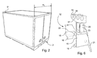
- FIG 2 With reference to figure 2 there is shown a schematic perspective representation of a container 1 according to an example embodiment of the invention, the width of the container being designated by W C .
- FIG 3 With reference to figure 3 there is shown a schematic perspective representation of a plurality of containers 1 according to the invention arranged side-by-side and on top of each other.
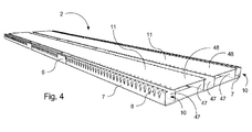
- FIG 4 there is shown a schematic perspective representation of an example embodiment of the attachment structure 2 according to the invention.
- This structure comprises parallel spaced elongated attachment/support members 10at either edge portions of the structure, which parallel spaced elongated attachment/support members 10 comprise laterally facing guide and engagement surfaces 7 that 7 are provided with locking openings 8 extending through the surfaces. These locking apertures could have any appropriate shape, not only the one actually shown in the figures.
- the attachment structure 2 according to this embodiment of the invention comprises further structural elements 47 and 48 that (together with a container attached to the structure) provide rigidity to the structure.
- FIG 5 there is shown a schematic perspective representation of the attachment structure shown in figure 4 attached to a support structure 31 according to an embodiment of the invention, which support structure in the shown example comprises three transverse support members 13 that can be mounted on a suitable transportation vehicle, wherein the laterally facing guide and engagement surfaces 7 of the attachment structure 2 are secured to the transverse support members 13 by means of releasable locking mechanisms 12, each being in locking engagement with corresponding openings 8 in the laterally facing guide and engagement surfaces 7.
- an end beam 13' is provided with an abutment 14 that prevents the attachment structure from being pushed further to the left (as seen in figure 5 ) than the position defined by the end beam 13'.
- FIG 6 there is shown a schematic perspective representation of an embodiment of a releasable locking mechanism generally designated by reference numeral 12 for locking the container to an underlying structure for instance on a lorry.
- the locking mechanism 12 comprises opposing support portions 15, 16, where the portion 16 can be attached to the transverse support members 13 shown in figures 4 and 5 .
- a locking means as such, which comprises a support plate 17 on which is provided locking members 18, 19 that are formed for insertion into the openings 8 provided in the laterally facing guide and engagement surfaces 7 of the attachment structure 2.
- FIG 7 there is shown a schematic view corresponding to that of figure 6 showing locking mechanisms 12 being provided on a number of transverse support members 13, the locking mechanisms 12 being in locking engagement with the attachment structure 2. Also, the abutment 14 described above is shown mounted to the transverse support member 13 furthest to the right in figure 7 .
- FIG 8 there is shown a schematic perspective representation of a lorry 25 that can be used in connection with the containers/swap boxes of the present invention, the lorry 25 being shown prior to the provision of the transverse support members 13 as for instance shown in figure 7 .
- These members 13 are to be attached to the longitudinal chassis beams 26 of the lorry as shown in figure 9 .
- the distance between the outwardly facing surfaces of the respective beams 26 is designated by D and the distance between the inner surfaces of the wheels is designated by Dw.
- FIG 9 there is shown a schematic perspective representation of the lorry 25 of figure 8 provided with transverse support members 13 and locking mechanisms 12 provided on some of the transverse support members 13. It would also be possible to provide locking mechanisms 12 on all of the transverse support members 13, if desired.
- the provision of locking mechanisms on all support members 13 increases the strength and stability of the connection between the attachment structure and the support structure.
- the optimum number of transverse support members 13 to be used depends among others on the dimensions of the container/swap box to be attached to the support structure 31 and on the weight of the container/swap box.
- the transverse support members 13 are at either longitudinal end provided with support and guide structures 27 for guiding the attachment structure on the container/swap box into its correct position on the transverse support members 13 during loading of the container/swap box on the lorry 25.
- the support and guide structure 27 comprises a support portion 28 for attachment to the transverse support member 13, outwardly inclined guide portions 29 for guiding the attachment structure on the container/swap box into its proper position on the transverse support members 13 and inwardly facing guide and retaining surfaces 30 for providing lateral support for the attachment structure, once the container 1 and associated attachment structure 2 is in the final position on the transverse support members 13.
- the process of locating an attachment structure 2 into the support structure is illustrated by the sequence of pictures shown in figures 10, 11 and 12 .
- the transverse support member 13 and the support and guide structure 27 are characterized by the parameters W B , i.e. the longitudinal extension of the transverse support member 13 and W S , i.e. the distance along the respective transverse support member 13 between the opposing inwardly facing guide and retaining surfaces 30.
- W B the longitudinal extension of the transverse support member 13
- W S the distance along the respective transverse support member 13 between the opposing inwardly facing guide and retaining surfaces 30.
- the support and guide structure 27 comprises through openings 33 for attachment to the underlying transverse support member 13. Other means of attachment would of cause also be possible. Further, two separate outwardly inclined guide portions 29 are provided in the illustrated embodiment of the support and guide structure 27, but a single inclined guide portion could alternatively be used.
- Figure 10 further shown the provision of a central support surface 34 on the transverse support member 13 upon which a corresponding portion of the attachment structure 2 can be supported.
- the attachment structure 2 is thus supported on each transverse support member 13 by the three support surfaces 28 and 34.
- Other arrangements of support surfaces may alternatively be used.
- FIGS. 14 , 15 and 16 there are shown schematic perspective representations that illustrate the loading of a container 1 according to the invention on a lorry 25.
- the maximum width of the container and support structure is determined by the distance D W between the wheels of the lorry.
- FIG 17 there is shown a schematic perspective representation of an alternative transport vehicle (a trailer) generally designated by reference numeral 32 that can be used with the containers according to the invention.
- the trailer 32 is in this embodiment provided with two transverse support members 13 as described above resting on, and fixed to the chassis beams 26 of the trailer.
- the various elements shown in the figure are designated by the same reference numerals as the corresponding elements described above.
- the transverse support members 13 can be provided with series of openings 34 for attachment of the respective support and guide structure 27 at the appropriate locations on the transverse support members 13.
- FIG 18 there is shown the trailer 32 of figure 17 provided with one example of a container, in the shown example in the shape of an upwardly open box 35.
- a container in the shown example in the shape of an upwardly open box 35.
- other kinds of containers could be used instead of the box 35, for instance swap boxes.
- Such alternatives are shown in figures 19 and 20 .
- D, W S and W B are: D ⁇ 1.1 meters, W B ⁇ 1.1 meters and W B,min ⁇ W S ⁇ W B , where W B,min is determined be the transversal distance between the laterally facing guide and engagement surfaces 7 of the specific attachment structure 2 to be used together with the specific support structure 31.
- Containers 1 can for instance be stacked 36 or be placed on suitable vehicles such as the trailers 37 shown in the figure.
- An automobile 41 may pick up a trailer with a container and leave the transit area 46, or a lorry 42 may pick up a trailer 40 provided with support means according to the invention after which a container is placed on the trailer for instance by means of a fork lift.
- the container according to the invention may also be provided directly on the bed of a lorry 43 that is provided with support means according to the invention. Distribution of the goods in the containers according to the invention finally takes place by means of environmental friendly vehicles as indicated by reference numerals 45 and 46.
- the flexible and versatile containers and transport vehicles according to the invention makes it easy and economically attractive to re-load goods from less environmental friendly and possibly larger vehicles to more environmental friendly and possibly smaller vehicles, that can furthermore be more easy to maneuver within an inner region of a city with narrow streets and much traffic.
- the invention facilitates easy and flexible distribution of goods by means of environmental friendly vehicles for instance within the inner region of a city.
Landscapes
- Engineering & Computer Science (AREA)
- Mechanical Engineering (AREA)
- Transportation (AREA)
- Health & Medical Sciences (AREA)
- Public Health (AREA)
- Details Of Rigid Or Semi-Rigid Containers (AREA)
- Fittings On The Vehicle Exterior For Carrying Loads, And Devices For Holding Or Mounting Articles (AREA)
Abstract
Description
- The present invention relates generally to containers and similar means for accommodating goods to be transported and more specifically to means for releasable attachment of such containers to a transport means, such as trucks, lorries, trailers or railway wagons. The invention furthermore relates to the use of such containers and transport means for distributing goods in an environmentally friendly manner, for instance within a city.
- The field of cargo transport faces a number of challenges. In known and existing goods distribution transfer systems the goods are collected in the country and outside of the country and transported over individual routes. All transport has to go through the outer zones of the city. This results in a great deal of traffic with conventional combustion engine driven or vehicles in the peripheral zone of the city leading to dense-traffic situations, high emission levels and noise levels. Traditionally, delivery of goods in the inner zone of a city takes place with large or small distribution vehicles of any kind, which vehicles may not be particularly friendly to the environment.
-
US3363803 describes an attachment structure for supporting and releasably attaching a container, cargo bed or the like to a transport vehicle. The attachment structure has two parallel spaced elongated attachment members. The elongated attachment members have a downwardly facing support surface for abutting an upwardly directed support surface of a support structure on the transport vehicle. The elongated attachment members are provided with a laterally facing guide and engagement surface. - It would hence be desirable to provide transportation means that are friendly to the environment and which can take care of transport of goods for instance in the inner regions of a city.
- On this background, it is an object of the invention to provide transport vehicles and transport means that allow environmentally friendly transport of goods primarily - although not necessarily - within the inner regions of cities. This object can be achieved by the provision of containers or swap boxes that are provided with means for easy and effective loading and unloading on/from transport vehicles. To this effect, the containers/swap boxes of the present invention are provided with means for releasable attachment to mating means provided on a transport vehicle, preferably a vehicle of a kind that is particularly friendly to the environment. Such vehicles could for instance be battery-powered distribution vehicles. The advantages of such vehicles are low emission, low noise level, and good battery longevity for short distance distribution.
- It is noted that although the specific term "container" is used throughout this specification, sometimes together with the alternative term "swap box", a "container" should be interpreted broadly to comprise any means that can accommodate goods to be transported and/or stored. Thus, for instance, an upwardly open box of wood or any other material will also fall within the scope of the term "container" as used in this specification.
- A further advantage of small vehicles is that they are more maneuverable in the city, and are better for traffic safety.
- According to an embodiment of the invention, vehicles that are categorized as environmentally friendly are either electric battery powered or powered by an environmental friendly combustion engine or powered by a combination of an electric battery and an environmental friendly combustion engine.
- The objects of the invention are solved by the provision of containers or similar means that are provided with an attachment structure that is either a separate structure that can be attached to the bottom surface of the container or which is formed as an integral part of the container. The attachment structure is designed such that it can be releasably attached and secured to a corresponding support structure that is either a separate structure or an integral structure on a transport vehicle, such as a truck, lorry, trailer or railway wagon.
- Preferably, the support structure is a separate structure that is designed such that it can be attached to any suitable vehicle despite differences in the construction/chassis frame of the vehicle.
- Preferably, the support structure is provided with quick lock mechanisms that allow quick and easy locking of the attachment structure to the support structure, and thereby the container to the transport vehicle, upon which the support structure is provided. Such quick lock mechanisms allow for securing and releasing without the use of tools.
- According to a first aspect of the present invention there is provided an attachment structure for supporting and releasably attaching a container, cargo bed or the like to a transport vehicle, where the container or cargo bed has a length and a width, and where the attachment structure comprises two parallel spaced elongated attachment/support members that extend along at least most of the length of the container or cargo bed, where the elongated attachment members comprises a downwardly facing support surface for abutting an upwardly directed support surface of a support structure on the transport vehicle, where the elongated attachment members are provided with a laterally facing guide and engagement surface, that is provided with recesses or apertures for entering in a locking engagement with a lock mechanism associated with the transport vehicle.
- According to a second aspect of the invention there is provided a container comprising an attachment structure as described above.
- According to an implementation of the second aspect, the attachment structure is a separate entity as described above, but it can alternatively be formed as an integral part of the container.
- According to a third aspect of the invention there is provided a support structure for supporting and securing a container, cargo bed or the like to a transport means, such as a vehicle or railway wagon, where the support structure comprises a plurality of transverse support members for supporting an attachment structure according to the invention as described above and a plurality of locking members provided on respective locking mechanisms for releasable locking of the attachment structure to the support structure.
- According to a fourth aspect of the invention, there is provided transport means, such as a truck, lorry, trailer, train wagon etc. for transporting containers, where the transport means is provided with a support structure as described above. This support structure can either be formed as a separate entity that can be mounted on a transport means on demand or be formed as an integral part of a transport means.
- According to a fifth aspect, the invention relates to an assembly of an attachment structure according to the invention and a support structure according to the invention, where the attachment structure is provided with means that are adapted to enter into a locking and releasable engagement with mating means provided on the support structure.
- According to a sixth aspect, the invention relates to the use of containers and transport vehicles according to the invention for environmentally friendly transport and distribution of goods for instance in central parts of a city. The flexible and versatile containers provided with an attachment structure according to the invention together with transport vehicles provided with support structures according to the invention makes it easy to re-load goods from larger and less environmental friendly vehicles unto transport vehicles/containers according to the invention and distribute the good for instance within a central part of a city, where transport using larger and less environmental friendly vehicles would be problematic.
- Although in the following detailed description of the invention the example embodiments show application of the principles of the invention specifically on road vehicles, such as trucks, lorries or trailers, it is understood that other transportation means, such as trains, could also be used, and that the application of such means would also fall within the scope of the present invention.
- Further objects, features, advantages and properties of the platform system according to the disclosure will become apparent from the detailed description.
- In the following detailed portion of the description, the invention will be explained in more detail with reference to the exemplary embodiments shown in the drawings, in which:
-
Fig. 1 is a schematic perspective representation of a container according to en example embodiment of the invention showing attachment means provided at the bottom surface of the container; -
Fig. 2 is a schematic perspective representation of a container according to en example embodiment of the invention; -
Fig. 3 is a schematic perspective representation of a plurality of containers according to the invention arranged side-by-side and on top of each other; -
Fig. 4 is a schematic perspective representation of an example embodiment of the attachment structure according to the invention that is provided at the bottom surface of the container; -
Fig. 5 is a schematic perspective representation of the attachment structure shown infigure 4 attached to three transversal beams mounted on a suitable transportation vehicle, wherein the attachment structure is secured to the beams by means of releasable locking members; -
Fig. 6 is a schematic perspective representation of an embodiment of releasable locking member for locking the container to an underlying structure for instance on a truck; -
Fig. 7 is a schematic view corresponding to that of figure six showing the locking means being provided on a number of transversal beams mounted on for instance a truck, the locking means being in locking engagement with the attachment structure; -
Fig. 8 is a schematic perspective representation of a lorry that can be used in connection with the containers of the present invention, prior to the provision of transversal beams as for instance shown infigure 7 ; -
Fig. 9 is a schematic perspective representation of the lorry of figure eight provided with transversal beams and locking means provided on some of the transversal beams; -
Fig. 10, 11, 12 and 13 are schematic perspective representations that illustrate the provision of edge guide means at the longitudinal ends of the transversal beams for guiding the container with its attachment structure into its proper position on the transversal beams; -
Fig. 14 ,15 and16 are schematic perspective representations that illustrate the loading of a container according to the invention on a lorry; -
Fig. 17 is a schematic perspective representation of an alternative transport vehicle (a trailer) that can be used with the containers according to the invention, the vehicle being provided with two transversal beams according to an example embodiment of the invention; -
Fig. 18 is a schematic perspective representation of the use of an alternative container on the trailer shown in figure seventeen; -
Fig. 19 is a schematic perspective representation of the provision on the trailer of a container of the same kind as shown for instance in figure one; -
Fig. 20 is a schematic perspective representation of a container according to the invention provided on still another kind of transport vehicle; and -
Fig. 21 is a schematic perspective representation of an example use of containers and transport means according to the invention. - In the following a detailed description example embodiments of attachment structures, containers, support structures and transport vehicles according to the invention are given, but it is understood that these embodiments only constitute non-limiting examples of how the present invention can be implemented in practice. Also, a practical example of using these various means fro environmental friendly transport of goods is given.
- With reference to
figure 1 there is shown a schematic perspective representation of a container according to a first example embodiment of the invention. The container is generally indicated byreference numeral 1 and is provided with anattachment structure 2 at the bottom surface of the container. In thebottom portion 4 of thecontainer 1 there are providedrecesses 5 for engagement with lift means of for instance a forklift. Extending longitudinally through thebottom portion 4 the is provided anattachment structure 2 according to an example embodiment of the invention for attaching and locking the container to asupport structure 31 on a transport vehicle, as will be described in detail below. The attachment structure comprises laterally facing guide and engagement surfaces orrails 7 that are provided with throughapertures 8 for locking the attachment structure to a support structure 31 (seefigures 5 and7 ) provided on a transport vehicle. Throughapertures 6 for the passage of lift means of for instance a forklift are also provided in therespective rails 7 at locations corresponding to therecesses 5 in the edge portion of thebottom portion 4 of the container. Thecontainer 1 may further be provided with retaining means allowing containers to be stacked upon each other, here shown as anopening 9 corresponding with a mating means 9' (not shown) provided at the top portion of the container. It is understood that although theattachment structure 2 in this embodiment extends longitudinally along the bottom portion of the container it would also be possible to provide the attachment structure at other angles relative to thebottom portion 4, for instance in a transversal direction relative to the bottom portion. - With reference to
figure 2 there is shown a schematic perspective representation of acontainer 1 according to an example embodiment of the invention, the width of the container being designated by WC. - With reference to
figure 3 there is shown a schematic perspective representation of a plurality ofcontainers 1 according to the invention arranged side-by-side and on top of each other. - With reference to
figure 4 there is shown a schematic perspective representation of an example embodiment of theattachment structure 2 according to the invention. This structure comprises parallel spaced elongated attachment/support members 10at either edge portions of the structure, which parallel spaced elongated attachment/support members 10 comprise laterally facing guide andengagement surfaces 7 that 7 are provided with lockingopenings 8 extending through the surfaces. These locking apertures could have any appropriate shape, not only the one actually shown in the figures. Through the parallel spaced elongated attachment/support members 10 7 there also extend theopenings 6 referred to above. Theattachment structure 2 according to this embodiment of the invention comprises furtherstructural elements - With reference to
figure 5 there is shown a schematic perspective representation of the attachment structure shown infigure 4 attached to asupport structure 31 according to an embodiment of the invention, which support structure in the shown example comprises threetransverse support members 13 that can be mounted on a suitable transportation vehicle, wherein the laterally facing guide andengagement surfaces 7 of theattachment structure 2 are secured to thetransverse support members 13 by means of releasable lockingmechanisms 12, each being in locking engagement withcorresponding openings 8 in the laterally facing guide and engagement surfaces 7. As it appears more clearly fromfigure 7 , an end beam 13' is provided with anabutment 14 that prevents the attachment structure from being pushed further to the left (as seen infigure 5 ) than the position defined by the end beam 13'. - With reference to
figure 6 there is shown a schematic perspective representation of an embodiment of a releasable locking mechanism generally designated byreference numeral 12 for locking the container to an underlying structure for instance on a lorry. Thelocking mechanism 12 comprises opposingsupport portions portion 16 can be attached to thetransverse support members 13 shown infigures 4 and5 . On theaxle 22 extending between the opposingsupport portions 15 there is provided a locking means as such, which comprises asupport plate 17 on which is provided lockingmembers openings 8 provided in the laterally facing guide andengagement surfaces 7 of theattachment structure 2. Due to the shape of theopenings 8 it is possible to insert the lockingmembers lever arrangement stem portion 18 of the locking members into the narrow portion of theopenings 8. In this position of the lockingmembers transverse support member 13, and hence to a vehicle, upon which these members are mounted. - It is understood that other locking means than the one actually described above could also be used and that the application of such alternative locking means would also fall within the scope of the present invention.
- With reference to
figure 7 there is shown a schematic view corresponding to that offigure 6 showing locking mechanisms 12 being provided on a number oftransverse support members 13, the lockingmechanisms 12 being in locking engagement with theattachment structure 2. Also, theabutment 14 described above is shown mounted to thetransverse support member 13 furthest to the right infigure 7 . - With reference to
figure 8 there is shown a schematic perspective representation of alorry 25 that can be used in connection with the containers/swap boxes of the present invention, thelorry 25 being shown prior to the provision of thetransverse support members 13 as for instance shown infigure 7 . Thesemembers 13 are to be attached to the longitudinal chassis beams 26 of the lorry as shown infigure 9 . The distance between the outwardly facing surfaces of therespective beams 26 is designated by D and the distance between the inner surfaces of the wheels is designated by Dw. These dimensions impose limitations on the dimensions of the various structures according to the invention as will be described below. Distance D is typically 900 mm, 110 mm or 1300 mm, depending on the make and model of the vehicle. - With reference to
figure 9 there is shown a schematic perspective representation of thelorry 25 offigure 8 provided withtransverse support members 13 and lockingmechanisms 12 provided on some of thetransverse support members 13. It would also be possible to providelocking mechanisms 12 on all of thetransverse support members 13, if desired. The provision of locking mechanisms on allsupport members 13 increases the strength and stability of the connection between the attachment structure and the support structure. The optimum number oftransverse support members 13 to be used depends among others on the dimensions of the container/swap box to be attached to thesupport structure 31 and on the weight of the container/swap box. Thetransverse support members 13 are at either longitudinal end provided with support and guidestructures 27 for guiding the attachment structure on the container/swap box into its correct position on thetransverse support members 13 during loading of the container/swap box on thelorry 25. - With reference to
figures 10, 11, 12 and 13 there are shown schematic perspective representations that illustrate the provision of the support and guidestructure 27 at chosen locations on thetransverse support members 13, for instance as shown at either the longitudinal end hereof for guiding thecontainer 1 with itsattachment structure 2 into its proper position on thetransverse support members 13. Specifically, the support and guidestructure 27 comprises asupport portion 28 for attachment to thetransverse support member 13, outwardlyinclined guide portions 29 for guiding the attachment structure on the container/swap box into its proper position on thetransverse support members 13 and inwardly facing guide and retainingsurfaces 30 for providing lateral support for the attachment structure, once thecontainer 1 and associatedattachment structure 2 is in the final position on thetransverse support members 13. The process of locating anattachment structure 2 into the support structure is illustrated by the sequence of pictures shown infigures 10, 11 and 12 . - As shown in
figure 11 , thetransverse support member 13 and the support and guidestructure 27 are characterized by the parameters WB, i.e. the longitudinal extension of thetransverse support member 13 and WS, i.e. the distance along the respectivetransverse support member 13 between the opposing inwardly facing guide and retaining surfaces 30. Although the support and guidestructure 27 is generally shown positioned at either longitudinal ends of the respectivetransverse support member 13, it would also be possible to locate the support and guidestructure 27 at other locations on the beam and hence with a distance WS that could be even substantially less than the longitudinal extension of thetransverse support member 13. Even an asymmetrical positioning of the opposing support and guidestructures 27 would be possible, if desired. - The support and guide
structure 27 comprises throughopenings 33 for attachment to the underlyingtransverse support member 13. Other means of attachment would of cause also be possible. Further, two separate outwardlyinclined guide portions 29 are provided in the illustrated embodiment of the support and guidestructure 27, but a single inclined guide portion could alternatively be used. -
Figure 10 further shown the provision of acentral support surface 34 on thetransverse support member 13 upon which a corresponding portion of theattachment structure 2 can be supported. In the shown embodiments, theattachment structure 2 is thus supported on eachtransverse support member 13 by the threesupport surfaces - With reference to
figures 14 ,15 and16 there are shown schematic perspective representations that illustrate the loading of acontainer 1 according to the invention on alorry 25. The maximum width of the container and support structure is determined by the distance DW between the wheels of the lorry. - With reference to
figure 17 there is shown a schematic perspective representation of an alternative transport vehicle (a trailer) generally designated byreference numeral 32 that can be used with the containers according to the invention. Thetrailer 32 is in this embodiment provided with twotransverse support members 13 as described above resting on, and fixed to the chassis beams 26 of the trailer. The various elements shown in the figure are designated by the same reference numerals as the corresponding elements described above. Thetransverse support members 13 can be provided with series ofopenings 34 for attachment of the respective support and guidestructure 27 at the appropriate locations on thetransverse support members 13. - With reference to
figure 18 there is shown thetrailer 32 offigure 17 provided with one example of a container, in the shown example in the shape of an upwardlyopen box 35. Alternatively, other kinds of containers could be used instead of thebox 35, for instance swap boxes. Such alternatives are shown infigures 19 and20 . - Although the scope of the invention is not limited to any specific numerical values of the various dimensions described above, typical values/ranges of the dimensions D, WS and WB are: D ≤ 1.1 meters, WB ≤ 1.1 meters and WB,min ≤ WS ≤ WB, where WB,min is determined be the transversal distance between the laterally facing guide and
engagement surfaces 7 of thespecific attachment structure 2 to be used together with thespecific support structure 31. - The fact that according to the invention it is possible to support and attach containers/attachment structures of a width within a broad range and if desired of a much smaller width than the distance D between the
beams 26 of the chassis of the transport vehicle makes the invention extremely useful for easy loading/reloading and transport of many different types and dimensions of containers. This ease of application is further increased by the provision of thequick lock mechanisms 12 on at least some of thetransverse support members 13. With reference tofigure 21 there is shown a schematic perspective representation of an example use of containers and transport means according to the invention. Goods have been delivered to atransit area 35 for instance on large trucks or on railway wagons (not shown in the figure) and stored incontainers 1 according to the invention.Containers 1 can for instance be stacked 36 or be placed on suitable vehicles such as thetrailers 37 shown in the figure. Anautomobile 41 may pick up a trailer with a container and leave thetransit area 46, or alorry 42 may pick up atrailer 40 provided with support means according to the invention after which a container is placed on the trailer for instance by means of a fork lift. The container according to the invention may also be provided directly on the bed of alorry 43 that is provided with support means according to the invention. Distribution of the goods in the containers according to the invention finally takes place by means of environmental friendly vehicles as indicated byreference numerals - It is an advantage of the invention that it provides for an attachment structure (2) for supporting and releasably attaching a
container 1, cargo bed or the like to atransport vehicle mating support structure 31 configured to be provided on thetransport vehicle mechanisms 12 configured to provide a releasable locking of theattachment structure 2 to thesupport structure 31. The invention facilitates easy and flexible distribution of goods by means of environmental friendly vehicles for instance within the inner region of a city. - Although the teaching of this application has been described in detail for purpose of illustration, it is understood that such detail is solely for that purpose, and variations can be made therein by those skilled in the art without departing from the scope of the teaching of this application.
- The term "comprising" as used in the claims does not exclude other elements or steps. The term "a" or "an" as used in the claims does not exclude a plurality.
Claims (14)
- An attachment structure for supporting and releasably attaching a container (1), cargo bed or the like to a transport vehicle (25, 30), said container (1) or cargo bed has a length and a width, said attachment structure comprises two parallel spaced elongated attachment/support members (10) that extend along at least most of the length of said container (1) or cargo bed, said elongated attachment members (10) comprising a downwardly facing support surface (35) for abutting an upwardly directed support surface (28) of a support structure (31) on said transport vehicle (25, 32), said elongated attachment members (10) are provided with a laterally facing guide and engagement surface (7), said laterally facing guide and engagement surface (7) being provided with recesses or apertures (8) for entering in a locking engagement with a lock mechanism (12) associated with said transport vehicle (25, 32).
- An attachment structure according to claim 1, wherein said laterally facing guide and engagement surfaces (7) are directed oppositely and outwardly facing and are spaced (Wa) so as to match the distance (Ws) of lateral and parallel spaced inwardly facing guide and retaining surfaces (30) of said support structure (31).
- An attachment structure according to claim 1 or 2, wherein said attachment structure (2) is a bed that can be located at the bottom of said container (1) or cargo bed or form the bottom of said container (1) or cargo bed.
- An attachment structure according to claims 1, 2 or 3, wherein the spacing (Wa) between the laterally facing guide and engagement surfaces (7) is substantially less than the width (Wc) of the container or cargo bed.
- An attachment structure according to any of the preceding claims 1 to 4, wherein said recesses or apertures (8) are distributed along substantially the entire longitudinal extension of said laterally facing guide and engagement surfaces (7), said recesses or apertures (8) preferably being substantially evenly distributed along substantially the entire longitudinal extension of said laterally facing guide and engagement surfaces (7) or substantially evenly distributed along one or more portions hereof.
- A container comprising an attachment structure according to any of the preceding claims 1 to 5, said attachment structure preferably being formed as an integral part of the container.
- A support structure (31) for supporting and securing a container (1), cargo bed or the like to a transport means (25, 32), such as a vehicle or railway wagon, said support structure (31) comprising a plurality of transverse support members (13) for supporting an attachment structure (2) according to any of the preceding claims 1 to 5, and a plurality of locking members (24) provided on respective locking mechanisms (12) for releasable locking of said attachment structure (2) to said support structure (31) with at least one of said transverse support members (13) preferably being provided with said locking mechanisms (12) at its either longitudinal ends.
- A support structure according to claim 7, wherein said locking mechanism (12) comprises locking members (18, 19) that are configured for releasable engagement with mating locking means (8) provided in said attachment structure (2).
- A support structure according to claim 7 or 8, wherein said locking mechanisms (12) are quick lock mechanisms comprising locking members (18, 19) configured to be inserted into said recesses or apertures (8) of the attachment structure (2) and upon activation of an actuator, such as for instance a handle (21), locking the locking members (18, 19) to corresponding of said recesses or apertures (8) and/or wherein at least some of said transverse support members (13) are provided with a pair of spaced apart support and guide structures (27) provided with an inwardly facing guide and retaining surfaces (30), where the distance (Ws) between the inwardly facing guide and retaining surfaces (30) of a given pair of support and guide structures (27) is substantially equal to or less than the distance (Wa) between said laterally facing guide and engagement surfaces (7) of said attachment structure (2) and/or wherein said support and guide structure (27) is provided with outwardly inclined guide portions (29) for guiding said attachment structure (2) into its final position on the transverse support member (13) and/ or wherein the width (WB) of the transverse support members (13) exceeds the typical exceeds the typical distance (D) between outer sides of the longitudinal beams (26) of a cargo vehicle (25, 32) and/or wherein said distance (Ws) between said inwardly facing guide and retaining surfaces (30) of a given pair of support and guide structures (27) is less than said width (WB) of the transverse support members (13).
- A support structure according to any of the preceding claims 7 to 9, wherein said transverse support members (13) are provided with a pattern of through holes or openings (34) distributed in the longitudinal direction of the transverse support member (13) for attachment of the transverse support member (13) to longitudinally extending beams (26) of the chassis of a transport vehicle (25, 32).
- A transport vehicle, such as e.g. a truck (25), lorry, trailer (30) or railway wagon, for transporting containers (1), said transport vehicle being provided with a support structure according to any of the preceding claims 7 to 10.
- An assembly comprising an attachment structure (2) according to any of the preceding claims 1 to 5 and a support structure (31) according to any of the preceding claims 7 to 10, wherein said laterally facing guide and engagement surfaces (7) of the attachment structure (2) are adapted to fit into the space formed between said inwardly facing guide and retaining surfaces (30) of the support structure (31).
- An assembly according to claim 12, wherein said laterally facing guide and engagement surfaces (7) are provided with recesses or apertures (8) for entering in a locking engagement with a lock mechanism (12) provided on the support structure (31).
- The use of one or more containers according to claim 6 and/or transport vehicles according to claim 11 for environmental friendly transport and distribution, the use comprising:(i) reloading goods from a less environmental friendly vehicle to a container according to claim 6;(ii) providing said container on a more environmental friendly vehicle according to claim 11; and(iii) distributing said goods within a given geographical area, such as an inner region of a city.
Applications Claiming Priority (1)
| Application Number | Priority Date | Filing Date | Title |
|---|---|---|---|
| DK201300623A DK178379B1 (en) | 2013-11-01 | 2013-11-01 | An attachment structure for supporting and releasably attaching a container, a corresponding support structure, a transport vehicle and a container |
Publications (2)
| Publication Number | Publication Date |
|---|---|
| EP2868523A2 true EP2868523A2 (en) | 2015-05-06 |
| EP2868523A3 EP2868523A3 (en) | 2016-09-21 |
Family
ID=51794821
Family Applications (1)
| Application Number | Title | Priority Date | Filing Date |
|---|---|---|---|
| EP14190711.3A Withdrawn EP2868523A3 (en) | 2013-11-01 | 2014-10-28 | An attachment structure for supporting and releasably attaching a container, a corresponding support structure, a transport vehicle and a container |
Country Status (3)
| Country | Link |
|---|---|
| US (1) | US9527426B2 (en) |
| EP (1) | EP2868523A3 (en) |
| DK (1) | DK178379B1 (en) |
Cited By (1)
| Publication number | Priority date | Publication date | Assignee | Title |
|---|---|---|---|---|
| CN109436791A (en) * | 2018-10-20 | 2019-03-08 | 沈靖林 | A kind of logistics transportation mobile loading and unloading clamp of container |
Families Citing this family (6)
| Publication number | Priority date | Publication date | Assignee | Title |
|---|---|---|---|---|
| FR3002193B1 (en) * | 2013-02-20 | 2015-04-03 | Sh2M | UTILITY VEHICLE WITH MODULAR BODY |
| US9884575B2 (en) * | 2016-05-25 | 2018-02-06 | Dropstor, Inc. | Container having a spring-counter-balanced ramp wall |
| GB2570099B (en) * | 2017-11-08 | 2021-09-08 | George Arrowsmith Mark | Utility trailer, utility trailer system and methods of configuring utility trailers |
| US12221183B2 (en) * | 2020-03-06 | 2025-02-11 | Terry Repp | Trailer and interchangeable modules |
| US20230182835A1 (en) * | 2021-12-14 | 2023-06-15 | Anthony W. Phelps | Configurable trailer |
| CN117087520A (en) * | 2023-10-08 | 2023-11-21 | 福建中青时代新能源科技有限公司 | A battery box placement device and battery box transport vehicle |
Citations (1)
| Publication number | Priority date | Publication date | Assignee | Title |
|---|---|---|---|---|
| US3363803A (en) | 1967-02-21 | 1968-01-16 | Strick Corp | Corner member for van size cargo container |
Family Cites Families (7)
| Publication number | Priority date | Publication date | Assignee | Title |
|---|---|---|---|---|
| US3259400A (en) * | 1964-04-01 | 1966-07-05 | Fruehauf Corp | Semi-trailer apparatus for vehicu-larizing containers |
| DE4027586A1 (en) * | 1989-09-08 | 1991-03-21 | Zeppelin Metallwerke Gmbh | Locking device for container on vehicle chassis - consists of centering bolts on contained and holders on chassis |
| DE4236513C2 (en) * | 1992-10-26 | 1997-07-10 | Inst Schienenfahrzeuge | Container arrangements in one or two-story freight and double-decker coaches, especially for high speeds |
| DE9318630U1 (en) * | 1993-12-06 | 1994-03-03 | Waggonbau Dessau Gmbh, 06844 Dessau | Keyhole plate system, especially for the side walls of a swap body |
| US5829946A (en) * | 1995-01-24 | 1998-11-03 | Mcneilus Truck And Manufacturing, Inc. | Detachable truck body and handling mechanism |
| CA2482342A1 (en) * | 2004-01-12 | 2005-07-12 | Aus Struct Services Pty Ltd. | Work platform |
| FR2933649B1 (en) * | 2008-07-09 | 2011-02-11 | Fbi | FIXING AND LOCKING DEVICE IN POSITION OF A BODY ON THE CHASSIS OF A BEARING, TRAILING AND SEMI-TRAILER VEHICLE |
-
2013
- 2013-11-01 DK DK201300623A patent/DK178379B1/en not_active IP Right Cessation
-
2014
- 2014-10-28 EP EP14190711.3A patent/EP2868523A3/en not_active Withdrawn
- 2014-10-30 US US14/528,092 patent/US9527426B2/en active Active
Patent Citations (1)
| Publication number | Priority date | Publication date | Assignee | Title |
|---|---|---|---|---|
| US3363803A (en) | 1967-02-21 | 1968-01-16 | Strick Corp | Corner member for van size cargo container |
Cited By (2)
| Publication number | Priority date | Publication date | Assignee | Title |
|---|---|---|---|---|
| CN109436791A (en) * | 2018-10-20 | 2019-03-08 | 沈靖林 | A kind of logistics transportation mobile loading and unloading clamp of container |
| CN109436791B (en) * | 2018-10-20 | 2020-07-24 | 黄石新港港口股份有限公司 | Commodity circulation is container removal loading and unloading anchor clamps for transportation |
Also Published As
| Publication number | Publication date |
|---|---|
| DK178379B1 (en) | 2016-01-25 |
| US20150125232A1 (en) | 2015-05-07 |
| EP2868523A3 (en) | 2016-09-21 |
| US9527426B2 (en) | 2016-12-27 |
| DK201300623A1 (en) | 2015-05-11 |
Similar Documents
| Publication | Publication Date | Title |
|---|---|---|
| US9527426B2 (en) | Attachment structure for supporting and releasably attaching a container, a corresponding support structure, a transport vehicle and a container | |
| US9422015B1 (en) | Extendable truck chassis with roller bogie | |
| US8740526B2 (en) | Load beam assembly | |
| US20080232921A1 (en) | Method and device for restraining a cargo pallet | |
| US7874773B2 (en) | Chassis packing system | |
| US20070170676A1 (en) | Dolly, and transportation using same | |
| US7963731B2 (en) | Thermoformed separator pad | |
| WO2001094243A2 (en) | Metal skid | |
| US9604656B2 (en) | Wheel chock storage apparatuses and methods of using the same | |
| US8978519B2 (en) | Tire chain installation ramp | |
| JP4772094B2 (en) | Container chassis towed by tractor | |
| EP1641669B1 (en) | System for connecting units to a truck and a device forming part of the system | |
| CN103661444B (en) | A kind of upper strata moving floor of double-layered transport vehicles rolling stock and using method thereof | |
| CN110139779B (en) | Transportation platform | |
| JP4807839B2 (en) | Commercial vehicle bodywork placement mechanism | |
| RU2270114C2 (en) | Multipurpose railway platform body | |
| CN110509943A (en) | Vehicle frame and flatcar | |
| JPS6031440A (en) | Stack housing device for container trailer etc. | |
| CN104648496A (en) | Carriage of express logistics vehicle | |
| CN212243107U (en) | Bracket assembly | |
| CN202147721U (en) | Frame with curtain of box type semi-trailer | |
| KR200373892Y1 (en) | 3shaft axle equipment a minimum arrangement distance for enlargement load space of loading box | |
| EP1222347A1 (en) | Multiple automobile transport system | |
| KR20120139714A (en) | Motor vehicle having a lining module, lining module and composite group | |
| FR3127936A1 (en) | Crate for the transport of goods |
Legal Events
| Date | Code | Title | Description |
|---|---|---|---|
| PUAI | Public reference made under article 153(3) epc to a published international application that has entered the european phase |
Free format text: ORIGINAL CODE: 0009012 |
|
| 17P | Request for examination filed |
Effective date: 20141028 |
|
| AK | Designated contracting states |
Kind code of ref document: A2 Designated state(s): AL AT BE BG CH CY CZ DE DK EE ES FI FR GB GR HR HU IE IS IT LI LT LU LV MC MK MT NL NO PL PT RO RS SE SI SK SM TR |
|
| AX | Request for extension of the european patent |
Extension state: BA ME |
|
| PUAL | Search report despatched |
Free format text: ORIGINAL CODE: 0009013 |
|
| AK | Designated contracting states |
Kind code of ref document: A3 Designated state(s): AL AT BE BG CH CY CZ DE DK EE ES FI FR GB GR HR HU IE IS IT LI LT LU LV MC MK MT NL NO PL PT RO RS SE SI SK SM TR |
|
| AX | Request for extension of the european patent |
Extension state: BA ME |
|
| RIC1 | Information provided on ipc code assigned before grant |
Ipc: B60P 1/64 20060101AFI20160818BHEP Ipc: B60P 7/13 20060101ALI20160818BHEP |
|
| STAA | Information on the status of an ep patent application or granted ep patent |
Free format text: STATUS: REQUEST FOR EXAMINATION WAS MADE |
|
| R17P | Request for examination filed (corrected) |
Effective date: 20170714 |
|
| RBV | Designated contracting states (corrected) |
Designated state(s): AL AT BE BG CH CY CZ DE DK EE ES FI FR GB GR HR HU IE IS IT LI LT LU LV MC MK MT NL NO PL PT RO RS SE SI SK SM TR |
|
| STAA | Information on the status of an ep patent application or granted ep patent |
Free format text: STATUS: EXAMINATION IS IN PROGRESS |
|
| 17Q | First examination report despatched |
Effective date: 20231109 |
|
| STAA | Information on the status of an ep patent application or granted ep patent |
Free format text: STATUS: THE APPLICATION IS DEEMED TO BE WITHDRAWN |
|
| 18D | Application deemed to be withdrawn |
Effective date: 20250128 |