EP2868509A1 - Access ports for accessing covered fuel tanks of a work vehicle - Google Patents
Access ports for accessing covered fuel tanks of a work vehicle Download PDFInfo
- Publication number
- EP2868509A1 EP2868509A1 EP20140190733 EP14190733A EP2868509A1 EP 2868509 A1 EP2868509 A1 EP 2868509A1 EP 20140190733 EP20140190733 EP 20140190733 EP 14190733 A EP14190733 A EP 14190733A EP 2868509 A1 EP2868509 A1 EP 2868509A1
- Authority
- EP
- European Patent Office
- Prior art keywords
- housing
- cab
- work vehicle
- fuel tank
- cover
- Prior art date
- Legal status (The legal status is an assumption and is not a legal conclusion. Google has not performed a legal analysis and makes no representation as to the accuracy of the status listed.)
- Granted
Links
Images





Classifications
-
- B—PERFORMING OPERATIONS; TRANSPORTING
- B60—VEHICLES IN GENERAL
- B60K—ARRANGEMENT OR MOUNTING OF PROPULSION UNITS OR OF TRANSMISSIONS IN VEHICLES; ARRANGEMENT OR MOUNTING OF PLURAL DIVERSE PRIME-MOVERS IN VEHICLES; AUXILIARY DRIVES FOR VEHICLES; INSTRUMENTATION OR DASHBOARDS FOR VEHICLES; ARRANGEMENTS IN CONNECTION WITH COOLING, AIR INTAKE, GAS EXHAUST OR FUEL SUPPLY OF PROPULSION UNITS IN VEHICLES
- B60K15/00—Arrangement in connection with fuel supply of combustion engines or other fuel consuming energy converters, e.g. fuel cells; Mounting or construction of fuel tanks
- B60K15/03—Fuel tanks
- B60K15/063—Arrangement of tanks
-
- B—PERFORMING OPERATIONS; TRANSPORTING
- B60—VEHICLES IN GENERAL
- B60K—ARRANGEMENT OR MOUNTING OF PROPULSION UNITS OR OF TRANSMISSIONS IN VEHICLES; ARRANGEMENT OR MOUNTING OF PLURAL DIVERSE PRIME-MOVERS IN VEHICLES; AUXILIARY DRIVES FOR VEHICLES; INSTRUMENTATION OR DASHBOARDS FOR VEHICLES; ARRANGEMENTS IN CONNECTION WITH COOLING, AIR INTAKE, GAS EXHAUST OR FUEL SUPPLY OF PROPULSION UNITS IN VEHICLES
- B60K15/00—Arrangement in connection with fuel supply of combustion engines or other fuel consuming energy converters, e.g. fuel cells; Mounting or construction of fuel tanks
- B60K15/03—Fuel tanks
- B60K15/04—Tank inlets
- B60K15/05—Inlet covers
-
- B—PERFORMING OPERATIONS; TRANSPORTING
- B60—VEHICLES IN GENERAL
- B60K—ARRANGEMENT OR MOUNTING OF PROPULSION UNITS OR OF TRANSMISSIONS IN VEHICLES; ARRANGEMENT OR MOUNTING OF PLURAL DIVERSE PRIME-MOVERS IN VEHICLES; AUXILIARY DRIVES FOR VEHICLES; INSTRUMENTATION OR DASHBOARDS FOR VEHICLES; ARRANGEMENTS IN CONNECTION WITH COOLING, AIR INTAKE, GAS EXHAUST OR FUEL SUPPLY OF PROPULSION UNITS IN VEHICLES
- B60K15/00—Arrangement in connection with fuel supply of combustion engines or other fuel consuming energy converters, e.g. fuel cells; Mounting or construction of fuel tanks
- B60K15/03—Fuel tanks
- B60K15/063—Arrangement of tanks
- B60K15/067—Mounting of tanks
- B60K15/07—Mounting of tanks of gas tanks
-
- B—PERFORMING OPERATIONS; TRANSPORTING
- B60—VEHICLES IN GENERAL
- B60K—ARRANGEMENT OR MOUNTING OF PROPULSION UNITS OR OF TRANSMISSIONS IN VEHICLES; ARRANGEMENT OR MOUNTING OF PLURAL DIVERSE PRIME-MOVERS IN VEHICLES; AUXILIARY DRIVES FOR VEHICLES; INSTRUMENTATION OR DASHBOARDS FOR VEHICLES; ARRANGEMENTS IN CONNECTION WITH COOLING, AIR INTAKE, GAS EXHAUST OR FUEL SUPPLY OF PROPULSION UNITS IN VEHICLES
- B60K15/00—Arrangement in connection with fuel supply of combustion engines or other fuel consuming energy converters, e.g. fuel cells; Mounting or construction of fuel tanks
- B60K15/03—Fuel tanks
- B60K15/04—Tank inlets
- B60K15/05—Inlet covers
- B60K2015/0515—Arrangements for closing or opening of inlet cover
- B60K2015/053—Arrangements for closing or opening of inlet cover with hinged connection to the vehicle body
-
- B—PERFORMING OPERATIONS; TRANSPORTING
- B60—VEHICLES IN GENERAL
- B60K—ARRANGEMENT OR MOUNTING OF PROPULSION UNITS OR OF TRANSMISSIONS IN VEHICLES; ARRANGEMENT OR MOUNTING OF PLURAL DIVERSE PRIME-MOVERS IN VEHICLES; AUXILIARY DRIVES FOR VEHICLES; INSTRUMENTATION OR DASHBOARDS FOR VEHICLES; ARRANGEMENTS IN CONNECTION WITH COOLING, AIR INTAKE, GAS EXHAUST OR FUEL SUPPLY OF PROPULSION UNITS IN VEHICLES
- B60K15/00—Arrangement in connection with fuel supply of combustion engines or other fuel consuming energy converters, e.g. fuel cells; Mounting or construction of fuel tanks
- B60K15/03—Fuel tanks
- B60K15/063—Arrangement of tanks
- B60K2015/0638—Arrangement of tanks the fuel tank is arranged in the rear of the vehicle
-
- B—PERFORMING OPERATIONS; TRANSPORTING
- B60—VEHICLES IN GENERAL
- B60K—ARRANGEMENT OR MOUNTING OF PROPULSION UNITS OR OF TRANSMISSIONS IN VEHICLES; ARRANGEMENT OR MOUNTING OF PLURAL DIVERSE PRIME-MOVERS IN VEHICLES; AUXILIARY DRIVES FOR VEHICLES; INSTRUMENTATION OR DASHBOARDS FOR VEHICLES; ARRANGEMENTS IN CONNECTION WITH COOLING, AIR INTAKE, GAS EXHAUST OR FUEL SUPPLY OF PROPULSION UNITS IN VEHICLES
- B60K15/00—Arrangement in connection with fuel supply of combustion engines or other fuel consuming energy converters, e.g. fuel cells; Mounting or construction of fuel tanks
- B60K15/03—Fuel tanks
- B60K15/063—Arrangement of tanks
- B60K2015/0639—Arrangement of tanks the fuel tank is arranged near or in the roof
-
- B—PERFORMING OPERATIONS; TRANSPORTING
- B60—VEHICLES IN GENERAL
- B60Y—INDEXING SCHEME RELATING TO ASPECTS CROSS-CUTTING VEHICLE TECHNOLOGY
- B60Y2200/00—Type of vehicle
- B60Y2200/20—Off-Road Vehicles
- B60Y2200/22—Agricultural vehicles
- B60Y2200/221—Tractors
Definitions
- the present subject matter relates generally to work vehicles and, more particularly, to access ports for accessing the covered fuel tanks of a work vehicle.
- Work vehicles such as agricultural tractors, earth-moving vehicles and other vehicles, typically include one or more fuel tanks configured to hold fuel for powering the engine.
- fuel tanks configured to hold fuel for powering the engine.
- it is often desirable to hide the vehicle's fuel tank(s) from view for aesthetic purposes.
- it may be desirable to provide a protecting covering(s) for a fuel tank(s) in order to prevent damage to the tank(s).
- fuel tank coverings may serve aesthetic and/or protective purposes, such coverings also serve to limit operator access to the fuel tank(s).
- the present subject matter is directed to a work vehicle including a cab and a fuel tank coupled to the cab.
- the work vehicle may also include a cab housing configured to cover the fuel tank.
- the cab housing may define an access port configured to provide access to the fuel tank.
- the work vehicle may include a cover panel configured to be coupled to the cab housing so as to cover the access port.
- the present subject matter is directed to access ports for accessing one or more covered fuel tanks of a work vehicle.
- the work vehicle may include one or more housings configured to cover one or more fuel tanks mounted to portions of the vehicle.
- Each housing may define one or more access ports for accessing the fuel tank(s) disposed underneath such housing.
- each housing may include one or more cover panels configured to cover the access port(s).
- each cover panel may be removably or hingedly coupled to the housing at one of the access ports so that the panel may be removed or otherwise moved away from the access port when access to the fuel tank(s) is needed.
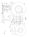
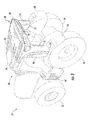
- FIGS. 1-7 illustrate various views of one embodiment of a work vehicle 20.
- the work vehicle 20 is configured as an agricultural tractor.
- the work vehicle 20 may be configured as any other suitable work vehicle known in the art, such as various other agricultural vehicles, earth-moving vehicles, loaders and/or various other off-road vehicles.
- the work vehicle 20 includes a pair of front wheels 22, a pair or rear wheels 24 and a chassis 26 coupled to and supported by the wheels 22, 24.
- An operator's cab 28 may be supported by a portion of the chassis 26 and may house various control or input devices (not shown) for permitting an operator to control the operation of the work vehicle 20.
- the work vehicle 20 may include an engine 30 ( FIG. 1 ) and a transmission 32 ( FIG. 1 ) mounted on the chassis 26.
- the transmission 32 may be operably coupled to the engine 30 and may provide variably adjusted gear ratios for transferring engine power to the wheels 24 via an axle/differential 34 ( FIG. 1 ).
- the work vehicle 20 may also include or more fuel tanks 36, 38, 40, 42 for containing fuel configured to be supplied to the engine 30 or any other suitable component of the vehicle 20.
- the fuel tanks 36, 38, 40, 42 may be configured to contain a pressurized or compressed fuel, such as methane or natural gas, hydrogen and/or any other suitable fuels.
- each fuel tank 36, 38, 40, 42 may correspond to a pressure vessel (e.g., a pressurized fluid cylinder) for containing the pressurized or compressed fuel.
- the fuel tanks 36, 38, 40, 42 may be configured to contain non-pressurized fuel, such as gasoline or diesel fuel.
- the fuel tanks 36, 38, 40, 42 may generally have any suitable configuration that allows the fuel to be contained therein.
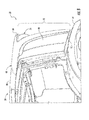
- one or more of the fuel tanks 36, 38, 40 may be coupled to the rear of the cab 28.
- a first fuel tank 36 is coupled to the left, rear of the cab 28 and extends vertically from generally adjacent to a left tire well 44 of the work vehicle 10 to generally adjacent to a top 46 of the cab 28.
- a second fuel tank 38 is coupled to the right, rear of the cab 28 and extends vertically from generally adjacent to a right tire well 48 of the work vehicle 10 to generally adjacent to the top 46 of the cab 28.
- a third fuel tank 40 is coupled to the rear of the cab 28 and extends horizontally generally adjacent to the top 46 of the cab 18 between the first and second fuel tanks 36, 38.
- any other suitable number of fuel tanks may be coupled to and/or disposed adjacent to the rear of the cab 28, such as less than three fuel tanks or greater than the three fuel tanks.
- the work vehicle 20 may also include one or more fuel tanks 42 located along one or both of the sides of the vehicle 20.
- one or more fuel tanks 42 located along the left side of the work vehicle 20 at a location adjacent to a cab ladder 50 defining steps 52 configured to provide an operator access to the left side of the cab 28.
- one or more fuel tanks may also be located on the right side of the work vehicle 20, such as at the location of the side housing 64 ( FIG. 3 ) positioned on the right side of the vehicle 20.
- the various fuel tanks 36, 38, 40, 42 of the work vehicle 20 may be located at any other suitable location on and/or along the vehicle 20.
- the fuel tanks 36, 38, 40, 42 may generally be configured to be coupled to portions of the work vehicle 20 at their respective positions using any suitable attachments means and/or method known in the art.
- the fuel tanks 36, 38, 40 are coupled to the rear of the cab 28 via suitable brackets 54 and mechanical fasteners 56.
- the side fuel tanks 42 are coupled to a portion of the work vehicle 20 adjacent to the cab ladder 50 using suitable brackets 54 and mechanical fasteners 56.
- the fuel tanks 36, 38, 40, 42 may be coupled to the work vehicle 20 at their respective positions using any other suitable attachments means.
- each tank 36, 38, 40, 42 may include a valve(s) 58 for opening/closing the tank 36, 38, 40, 42, thereby allowing the supply of fuel from each tank 36, 38, 40, 42 to be turned on and off.
- each tank 36, 38, 40, 42 may include a tank valve 58 located at one end of the tank 36, 38, 40, 42.
- the valve 58 may be configured to be manually opened and closed (e.g., a wheel valve) or automatically opened and closed (e.g., an electronically operated valve controlled via a controller of the vehicle 20).
- each fuel tank 36, 38, 40, 42 may include a fuel cap as opposed to the tank valve to allow the fuel tank 36, 38, 40, 42 to be opened and closed.
- the work vehicle 20 may also include one or more housings 60, 62, 64 configured to partially or fully encase, surround and/or otherwise cover the fuel tanks 36, 38, 40, 42.
- the work vehicle 20 includes a cab housing 60 configured to cover the fuel tanks 36, 38, 40 coupled to the rear of the cab 28.
- the work vehicle 20 may include a side housing(s) 62, 64 for covering any fuel tanks 42 located along the side of the work vehicle 20.
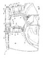
- the work vehicle 20 includes a first side housing 62 (shown as being transparent in FIG. 14 ) for covering the side tanks 42 located along the left side of the work vehicle 20.
- the work vehicle 20 may also include a second side housing 64 for covering any side tanks (not shown) located along the right side of the work vehicle 20.
- the various housings 60, 62, 64 may be configured to serve as protective coverings for the fuel tanks 36, 38, 40, 42.
- the housings 60, 62, 64 may also be configured to enhance the overall look, feel and/or design of the work vehicle 20. For instance, as opposed to simply mounting the fuel tanks 36, 38, 40, 42 to the exterior of the vehicle 20, the housings 60, 62, 64 may provide a more aesthetically pleasing look to the vehicle's exterior.
- the cab housing 60 may form all or a part of the housing component(s) that are configured to house and/or cover the various structural members and/or interior components of the cab 28.
- the cab housing 60 may be configured to extend horizontally along the top 46 of the cab 28 between a front end 66 disposed at the front the cab 28 and a rear end 68 disposed at the rear of the cab 28.
- the cab housing 60 may be configured to extend vertically along the rear of the cab 28 between the rear end 68 and a bottom end 70 located generally adjacent to the tire wells 44, 46.
- the cab housing 60 may be formed from multiple housing components configured to be coupled together or from a single housing component.
- the cab housing 60 described herein may simply be configured to correspond to the portion of the vehicle housing component(s) that extend around and/or cover the various fuel tanks 36, 38, 40 mounted at the rear of the cab 28.
- the cab housing 60 may include a first housing portion 72 configured to extend vertically along the left, rear of the cab 28 so as to fully or partially surround and/or cover the first fuel tank 36.
- the first housing portion 72 generally extends vertically between the rear and bottom ends 68, 78 of the cab housing 60 along the left, rear side of the cab 28.
- the cab housing 60 may include a second housing portion 74 configured to extend vertically along the right, rear of the cab 28 so as to fully or partially surround and/or cover the second fuel tank 38.
- the second housing portion 74 generally extends vertically between the rear and bottom ends 68, 78 of the cab housing 60 along the right, rear side of the cab 28.
- the cab housing 60 may include a third housing portion 76 extending horizontally along the top, rear of the cab 28 so as to fully or partially surround and/or cover the third fuel tank 42.
- the third housing portion 76 generally extends horizontally between the first and second housing portions 72, 74 along the rear end 68 of the cab housing 60.
- the cab housing 60 may be formed from multiple housing components or from a single housing component.
- the first, second and third housing portions 72, 74, 76 may be formed as separate components (e.g., separate housing panels) configured to be separately attached to one another.
- the first, second and third housing portions 72, 74, 76 may be formed integrally as a single component (e.g., a single molded housing component).
- the third housing portion 76 may be configured to accommodate one or more lighting components of the work vehicle 20.
- the third housing portion 76 may define a first recess 78 located adjacent to the left side of the cab housing 60 and a second recess 80 located adjacent to the right side of the cab housing 60.
- one or more lights or lighting modules 82 may be configured to be mounted to the cab housing 60 within each recess 78, 80.
- the side housing(s) 62, 64 of the work vehicle 20 may also have any suitable configuration that allows such housing(s) 62, 64 to at least partially surround and/or cover any side fuel tanks 42 of the vehicle 20.
- the first side housing 62 may be configured as an elongated cover extending lengthwise between a first end 84 and a second end 86 so as to define a height sufficient to allow one or more side tanks 42 to be positioned within the housing 62 along the left side of the work vehicle 20.
- the second side housing 64 may be configured to define any suitable dimension(s) that allows the housing 64 to at least partially surround and/or cover any side fuel tanks 42 located along the right side of the work vehicle 20.
- the second side housing 64 may also be configured to serve as ladder to allow an operator to gain access to the right side of the cab 28. Specifically, as shown in FIG. 3 , the second side housing 64 may define one or more steps 88 that may be used by an operator to move from the ground to a top side 90 of the housing 64 in order to access the right side of the cab 28.
- the housing(s) 60, 62, 64 may define one or more access ports 92, 94, 96 to allow an operator to access the fuel tank(s) 36, 38, 40, 42 located underneath each housing 60, 62, 64.
- an operator may be required to access the fuel tank(s) 36, 38, 40, 42 in order to manipulate the tank valve 58 (or fuel cap) associated with each tank 36, 38, 40, 42, to clean the fuel tanks 36, 38, 40, 42 and/or to perform any other suitable maintenance and/or service operation(s).
- the work vehicle 20 may also include one or more cover panels 98, 100, 102 configured to cover the access ports 92, 94, 96 when operator access to the fuel tank(s) 36, 38, 40, 42 is not required.
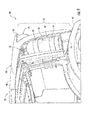
- FIGS. 8 and 9 illustrate a left side view of a portion of the work vehicle 20 shown in FIGS. 1-7 , particularly illustrating a side view of the first housing portion 72 of the cab housing 60.
- the first housing portion 72 may be configured to define a first access port 92 extending along the left side of the cab housing 60 in order to provide access to the first fuel tank 36 disposed therein.
- a first cover panel 98 may be configured to be coupled to the cab housing 60 so as to extend over and/or cover the first access port 92.
- the first cover panel 98 may be removed or otherwise moved away from the first access port 92 to allow access within the first housing portion 72.
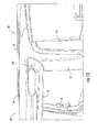
- FIGS. 10 and 11 illustrate a right side view of a portion of the work vehicle 20 shown in FIGS. 1-7 , particularly illustrating a side view of the second housing portion 74 of the cab housing 60.
- the second housing portion 74 may be configured to define a second access port 94 extending along the right side of the cab housing 60 in order to provide access to the second fuel tank 38 disposed therein.
- a second cover panel 100 may be configured to be coupled to the cab housing 60 so as to extend over and/or cover the second access port 94.
- the second cover panel 100 may be removed or otherwise moved away from the second access port 94 to allow access within the second housing portion 74.
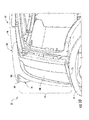
- FIGS. 12 and 13 illustrate a right, rear perspective view of a portion of the work vehicle 20 shown in FIGS. 1-7 , particularly illustrating a perspective view of the right side of the third housing portion 76 of the cab housing 60.
- the third housing portion 76 may be configured to define a third access port 96 at the top, right side of the cab housing 60 in order to provide access to the third fuel tank 40 disposed therein.
- a third cover panel 102 may be configured to be coupled to the cab housing 60 so as to extend over and/or cover third access port 96. Thus, when access to the third fuel tank 40 is required, the third cover panel 102 may be removed or otherwise moved away from the third access port 96 to allow access within the third housing portion 76.
- each access port 92, 94, 96 may generally vary depending on the amount of access to be provided to an operator. For example, as shown in FIGS. 9 and 11 , in one embodiment, each access port 92, 94, 96 may be large enough to access all or a significant portion of the corresponding fuel tank 36, 38, 40. However, as shown in FIG. 13 , in another embodiment, each access port 92, 94, 96 may only be configured to allow access to a small portion of the corresponding fuel tank 36, 38, 40, such as by providing access to the tank valve 58 associated with the fuel tank.
- the access ports 92, 94, 96 may generally be defined at any suitable location within the cab housing 60 that provides access to the fuel tank(s) 36, 38, 40 covered by the housing 60.
- the first and second access ports 92, 94 may be defined at any other suitable location(s), such as at the rear of each housing portion 72, 74 or along the inner side of each housing portion 72, 74 (e.g., the side facing the opposite housing portion 72, 74).
- the third access port 96 may be defined at any other suitable location, such as at the left side of third housing portion 76 or along the rear face of the housing portion 76 (e.g., along all or a portion of the face along which the lighting recesses 78, 80 are defined).
- cover panels 98, 100, 102 may generally be configured to be coupled to the cab housing 60 using any suitable means that allows each panel 98, 100, 102 to be moved relative to the cab housing 60 in order to allow access to its corresponding access port 92, 94, 96.
- the cover panels 98, 100, 102 may be configured to be removably coupled to the cab housing 60 at the location of each access port 92, 94, 96.
- suitable fastening mechanisms such as fasteners, clips, brackets and/or the like, may be used to couple the cover panels 98, 100, 102 to the cab housing 60.
- the fastening mechanisms may be removed, loosened or otherwise manipulated to allow each cover panel 98, 100, 102 to be removed from the cab housing 60 in order to expose the underlying access port 92, 94, 96.
- the cover panels 98, 100, 102 may simply be configured to be inserted into and removed from each access port 92, 94, 96.
- each cover panel 98, 100, 102 may be dimensioned such that, when the cover panel 98, 100, 102 is pushed into its corresponding access port 92, 94, 96, the cover panel 98, 100, 102 is retained within access port 92, 94, 96 via contact and/or engagement with the cab housing 60 and/or a component coupled to the cab housing 60 (e.g., a retaining clip or other feature).
- a component coupled to the cab housing 60 e.g., a retaining clip or other feature.
- each cover panel 98, 100, 102 may be configured to be hingedly coupled to the cab housing 60 at the location of each access port 92, 94, 96.
- each cover panel 98, 100, 102 may be coupled to the cab housing 60 using a hinge or any other suitable type of hinged or pivoting attachment mechanism.
- each cover panel 98, 100, 102 may be pivoted or otherwise moved relative to the cab housing 60 to allow access to the fuel tank(s) 36, 38, 40 via the corresponding access port 92, 94, 96.
- Similar access ports may also be defined in the side housing(s) 62, 64 to allow access to the interior of such housing(s) 62, 64.
- a side cover panel 104 may be coupled to the first side housing 62 to allow access to the side fuel tank(s) 42 contained therein.
- a side cover panel (not shown) may also be coupled to the second side housing 64 to allow access to any side fuel tanks 42 contained therein.
- the configuration of the work vehicle 20 described above and shown in the illustrated embodiment is provided only to place the present subject matter in an exemplary field of use.
- the present subject matter may be readily adaptable to any manner of work vehicle configuration.
- the disclosed fuel tanks 36, 38, 40, 42, housings 60, 62, 64, access ports 92, 94, 96, cover panels 98, 100, 102, 104 and/or any combination thereof may be provided on any other agricultural vehicle(s) and/or any other suitable type of work vehicle(s), such as earth-moving vehicles, loaders and/or various other off-road vehicles.
Landscapes
- Engineering & Computer Science (AREA)
- Life Sciences & Earth Sciences (AREA)
- Sustainable Development (AREA)
- Sustainable Energy (AREA)
- Chemical & Material Sciences (AREA)
- Combustion & Propulsion (AREA)
- Transportation (AREA)
- Mechanical Engineering (AREA)
- Cooling, Air Intake And Gas Exhaust, And Fuel Tank Arrangements In Propulsion Units (AREA)
- Body Structure For Vehicles (AREA)
Abstract
Description
- The present subject matter relates generally to work vehicles and, more particularly, to access ports for accessing the covered fuel tanks of a work vehicle.
- Work vehicles, such as agricultural tractors, earth-moving vehicles and other vehicles, typically include one or more fuel tanks configured to hold fuel for powering the engine. When designing a work vehicle, it is often desirable to hide the vehicle's fuel tank(s) from view for aesthetic purposes. In addition, it may be desirable to provide a protecting covering(s) for a fuel tank(s) in order to prevent damage to the tank(s). However, while fuel tank coverings may serve aesthetic and/or protective purposes, such coverings also serve to limit operator access to the fuel tank(s).
- Accordingly, a fuel tank covering or housing that provides an operator with proper access to the fuel tank(s) located underneath would be welcomed in the technology.
- Aspects and advantages of the invention will be set forth in part in the following description, or may be obvious from the description, or may be learned through practice of the invention.
- In one aspect, the present subject matter is directed to a work vehicle including a cab and a fuel tank coupled to the cab. The work vehicle may also include a cab housing configured to cover the fuel tank. The cab housing may define an access port configured to provide access to the fuel tank. In addition, the work vehicle may include a cover panel configured to be coupled to the cab housing so as to cover the access port.
- These and other features, aspects and advantages of the present invention will become better understood with reference to the following description and appended claims. The accompanying drawings, which are incorporated in and constitute a part of this specification, illustrate embodiments of the invention and, together with the description, serve to explain the principles of the invention.
- A full and enabling disclosure of the present invention, including the best mode thereof, directed to one of ordinary skill in the art, is set forth in the specification, which makes reference to the appended figures, in which:
-
FIG. 1 illustrates a left side view of one embodiment of a work vehicle in accordance with aspects of the present subject matter; -
FIG. 2 illustrates a left, rear perspective view of the work vehicle shown inFIG. 1 ; -
FIG. 3 illustrates a right, front perspective view of the work vehicle shown inFIG. 1 ; -
FIG. 4 illustrates a rear view of the work vehicle shown inFIG. 1 ; -
FIG. 5 illustrates another left, rear perspective view of the work vehicle shown inFIG. 1 ; -
FIG. 6 illustrates a right, rear perspective view of the work vehicle shown inFIG. 1 ; -
FIG. 7 illustrates a left, rear perspective view of a portion of the work vehicle shown inFIG. 1 , particularly illustrating a plurality of fuel tanks mounted to the rear of an operator's cab of the work vehicle; -
FIG. 8 illustrates a left side view of a portion of the work vehicle shown inFIG. 1 , particularly illustrating a portion of the left side of a housing that covers the fuel tanks coupled to the rear of the operator's cab; -
FIG. 9 illustrates another left side view of the portion of the work vehicle shown inFIG. 8 , particularly illustrating a panel of the housing removed so as to provide an access port for accessing the fuel tank coupled to the left rear of the operator's cab; -
FIG. 10 illustrates a right side view of a portion of the work vehicle shown inFIG. 1 , particularly illustrating a portion of the right side of the housing that covers the fuel tanks coupled to the rear of the operator's cab; -
FIG. 11 illustrates another right side view of the portion of the work vehicle shown inFIG. 10 , particularly illustrating a panel of the housing removed so as to provide an access port for accessing the fuel tank coupled to the right rear of the operator's cab; -
FIG. 12 illustrates a right, rear perspective view of a portion of the work vehicle shown inFIG. 1 , particularly illustrating a portion of the rear of the housing that covers the fuel tanks coupled to the rear of the operator's cab; -
FIG. 13 illustrates another right, rear perspective view of the portion of the work vehicle shown inFIG. 12 , particularly illustrating a panel of the housing removed so as to provide an access port for accessing the fuel tank coupled to the top rear of the operator's cab; and -
FIG. 14 illustrates a partial perspective view of a portion of the work vehicle shown inFIG. 1 , particularly illustrating a transparent view of a side housing of the work vehicle to allow the fuel tanks covered by the housing to be viewed. - Reference now will be made in detail to embodiments of the invention, one or more examples of which are illustrated in the drawings. Each example is provided by way of explanation of the invention, not limitation of the invention. In fact, it will be apparent to those skilled in the art that various modifications and variations can be made in the present invention without departing from the scope or spirit of the invention. For instance, features illustrated or described as part of one embodiment can be used with another embodiment to yield a still further embodiment. Thus, it is intended that the present invention covers such modifications and variations as come within the scope of the appended claims and their equivalents.
- In general, the present subject matter is directed to access ports for accessing one or more covered fuel tanks of a work vehicle. Specifically, in several embodiments, the work vehicle may include one or more housings configured to cover one or more fuel tanks mounted to portions of the vehicle. Each housing may define one or more access ports for accessing the fuel tank(s) disposed underneath such housing. Additionally, each housing may include one or more cover panels configured to cover the access port(s). For example, each cover panel may be removably or hingedly coupled to the housing at one of the access ports so that the panel may be removed or otherwise moved away from the access port when access to the fuel tank(s) is needed.
- Referring now to the drawings,
FIGS. 1-7 illustrate various views of one embodiment of awork vehicle 20. As shown, thework vehicle 20 is configured as an agricultural tractor. However, in other embodiments, thework vehicle 20 may be configured as any other suitable work vehicle known in the art, such as various other agricultural vehicles, earth-moving vehicles, loaders and/or various other off-road vehicles. - As shown in the illustrated embodiment, the
work vehicle 20 includes a pair offront wheels 22, a pair orrear wheels 24 and achassis 26 coupled to and supported by thewheels cab 28 may be supported by a portion of thechassis 26 and may house various control or input devices (not shown) for permitting an operator to control the operation of thework vehicle 20. Moreover, thework vehicle 20 may include an engine 30 (FIG. 1 ) and a transmission 32 (FIG. 1 ) mounted on thechassis 26. Thetransmission 32 may be operably coupled to theengine 30 and may provide variably adjusted gear ratios for transferring engine power to thewheels 24 via an axle/differential 34 (FIG. 1 ). - As is generally understood, the
work vehicle 20 may also include ormore fuel tanks engine 30 or any other suitable component of thevehicle 20. In several embodiments, thefuel tanks FIGS. 7 and14 , eachfuel tank fuel tanks fuel tanks - As shown in
FIG. 7 , in several embodiments, one or more of thefuel tanks cab 28. Specifically, as shown, afirst fuel tank 36 is coupled to the left, rear of thecab 28 and extends vertically from generally adjacent to a left tire well 44 of the work vehicle 10 to generally adjacent to atop 46 of thecab 28. Additionally, asecond fuel tank 38 is coupled to the right, rear of thecab 28 and extends vertically from generally adjacent to aright tire well 48 of the work vehicle 10 to generally adjacent to thetop 46 of thecab 28. Moreover, athird fuel tank 40 is coupled to the rear of thecab 28 and extends horizontally generally adjacent to thetop 46 of the cab 18 between the first andsecond fuel tanks cab 28, such as less than three fuel tanks or greater than the three fuel tanks. - In addition, the
work vehicle 20 may also include one ormore fuel tanks 42 located along one or both of the sides of thevehicle 20. For example, as shown inFIG. 14 , twoside tanks 42 are located along the left side of thework vehicle 20 at a location adjacent to acab ladder 50 definingsteps 52 configured to provide an operator access to the left side of thecab 28. Although not shown, one or more fuel tanks may also be located on the right side of thework vehicle 20, such as at the location of the side housing 64 (FIG. 3 ) positioned on the right side of thevehicle 20. - It should be appreciated that, in other embodiments, the
various fuel tanks work vehicle 20 may be located at any other suitable location on and/or along thevehicle 20. - Additionally, the
fuel tanks work vehicle 20 at their respective positions using any suitable attachments means and/or method known in the art. For example, as shown inFIG. 7 , thefuel tanks cab 28 viasuitable brackets 54 andmechanical fasteners 56. Similarly, as shown inFIG. 14 , theside fuel tanks 42 are coupled to a portion of thework vehicle 20 adjacent to thecab ladder 50 usingsuitable brackets 54 andmechanical fasteners 56. In other embodiments, thefuel tanks work vehicle 20 at their respective positions using any other suitable attachments means. - It should be appreciated that, in embodiments in which the
fuel tanks tank tank tank FIGS. 7 and14 , eachtank tank valve 58 located at one end of thetank valve 58 may be configured to be manually opened and closed (e.g., a wheel valve) or automatically opened and closed (e.g., an electronically operated valve controlled via a controller of the vehicle 20). Alternatively, in embodiments in which thefuel tanks fuel tank fuel tank - Moreover, the
work vehicle 20 may also include one ormore housings fuel tanks work vehicle 20 includes acab housing 60 configured to cover thefuel tanks cab 28. Additionally, thework vehicle 20 may include a side housing(s) 62, 64 for covering anyfuel tanks 42 located along the side of thework vehicle 20. For example, as shown inFIGS. 1 ,2 ,5 and14 , thework vehicle 20 includes a first side housing 62 (shown as being transparent inFIG. 14 ) for covering theside tanks 42 located along the left side of thework vehicle 20. Similarly, as shown inFIGS. 3 and6 , thework vehicle 20 may also include asecond side housing 64 for covering any side tanks (not shown) located along the right side of thework vehicle 20. It should be appreciated that thevarious housings fuel tanks housings work vehicle 20. For instance, as opposed to simply mounting thefuel tanks vehicle 20, thehousings - In several embodiments, the
cab housing 60 may form all or a part of the housing component(s) that are configured to house and/or cover the various structural members and/or interior components of thecab 28. For example, as shown in the illustrated embodiment, thecab housing 60 may be configured to extend horizontally along the top 46 of thecab 28 between afront end 66 disposed at the front thecab 28 and arear end 68 disposed at the rear of thecab 28. Additionally, thecab housing 60 may be configured to extend vertically along the rear of thecab 28 between therear end 68 and abottom end 70 located generally adjacent to thetire wells cab housing 60 may be formed from multiple housing components configured to be coupled together or from a single housing component. Alternatively, thecab housing 60 described herein may simply be configured to correspond to the portion of the vehicle housing component(s) that extend around and/or cover thevarious fuel tanks cab 28. - In several embodiments, the
cab housing 60 may include afirst housing portion 72 configured to extend vertically along the left, rear of thecab 28 so as to fully or partially surround and/or cover thefirst fuel tank 36. Specifically, as shown in the illustrated embodiment, thefirst housing portion 72 generally extends vertically between the rear and bottom ends 68, 78 of thecab housing 60 along the left, rear side of thecab 28. Additionally, thecab housing 60 may include asecond housing portion 74 configured to extend vertically along the right, rear of thecab 28 so as to fully or partially surround and/or cover thesecond fuel tank 38. For example, as shown in the illustrated embodiment, thesecond housing portion 74 generally extends vertically between the rear and bottom ends 68, 78 of thecab housing 60 along the right, rear side of thecab 28. Moreover, thecab housing 60 may include athird housing portion 76 extending horizontally along the top, rear of thecab 28 so as to fully or partially surround and/or cover thethird fuel tank 42. For instance, as shown in the illustrated embodiment, thethird housing portion 76 generally extends horizontally between the first andsecond housing portions rear end 68 of thecab housing 60. - As indicated above, in several embodiments, the
cab housing 60 may be formed from multiple housing components or from a single housing component. Thus, it should be appreciated that the first, second andthird housing portions third housing portions - Additionally, in several embodiments, the
third housing portion 76 may configured to accommodate one or more lighting components of thework vehicle 20. For example, as shown inFIGS. 4 and5 , thethird housing portion 76 may define afirst recess 78 located adjacent to the left side of thecab housing 60 and asecond recess 80 located adjacent to the right side of thecab housing 60. In such an embodiment, one or more lights orlighting modules 82 may be configured to be mounted to thecab housing 60 within eachrecess - Moreover, it should be appreciated that the side housing(s) 62, 64 of the
work vehicle 20 may also have any suitable configuration that allows such housing(s) 62, 64 to at least partially surround and/or cover anyside fuel tanks 42 of thevehicle 20. For example, as shown inFIGS 1 and14 , thefirst side housing 62 may be configured as an elongated cover extending lengthwise between afirst end 84 and asecond end 86 so as to define a height sufficient to allow one ormore side tanks 42 to be positioned within thehousing 62 along the left side of thework vehicle 20. Similarly, thesecond side housing 64 may be configured to define any suitable dimension(s) that allows thehousing 64 to at least partially surround and/or cover anyside fuel tanks 42 located along the right side of thework vehicle 20. - In one embodiment, the
second side housing 64 may also be configured to serve as ladder to allow an operator to gain access to the right side of thecab 28. Specifically, as shown inFIG. 3 , thesecond side housing 64 may define one ormore steps 88 that may be used by an operator to move from the ground to atop side 90 of thehousing 64 in order to access the right side of thecab 28. - Moreover, in several embodiments, the housing(s) 60, 62, 64 may define one or
more access ports housing tank fuel tanks work vehicle 20 may also include one ormore cover panels access ports - For example,
FIGS. 8 and9 illustrate a left side view of a portion of thework vehicle 20 shown inFIGS. 1-7 , particularly illustrating a side view of thefirst housing portion 72 of thecab housing 60. As particularly shown inFIG. 9 , thefirst housing portion 72 may be configured to define afirst access port 92 extending along the left side of thecab housing 60 in order to provide access to thefirst fuel tank 36 disposed therein. Additionally, as shown inFIG. 8 , afirst cover panel 98 may be configured to be coupled to thecab housing 60 so as to extend over and/or cover thefirst access port 92. Thus, when access to thefirst fuel tank 36 is required, thefirst cover panel 98 may be removed or otherwise moved away from thefirst access port 92 to allow access within thefirst housing portion 72. - Similarly,
FIGS. 10 and11 illustrate a right side view of a portion of thework vehicle 20 shown inFIGS. 1-7 , particularly illustrating a side view of thesecond housing portion 74 of thecab housing 60. As particularly shown inFIG. 11 , thesecond housing portion 74 may be configured to define asecond access port 94 extending along the right side of thecab housing 60 in order to provide access to thesecond fuel tank 38 disposed therein. Additionally, as shown inFIG. 10 , asecond cover panel 100 may be configured to be coupled to thecab housing 60 so as to extend over and/or cover thesecond access port 94. Thus, when access to thesecond fuel tank 38 is required, thesecond cover panel 100 may be removed or otherwise moved away from thesecond access port 94 to allow access within thesecond housing portion 74. - Moreover,
FIGS. 12 and13 illustrate a right, rear perspective view of a portion of thework vehicle 20 shown inFIGS. 1-7 , particularly illustrating a perspective view of the right side of thethird housing portion 76 of thecab housing 60. As particularly shown inFIG. 13 , thethird housing portion 76 may be configured to define athird access port 96 at the top, right side of thecab housing 60 in order to provide access to thethird fuel tank 40 disposed therein. Additionally, as shown inFIG. 12 , athird cover panel 102 may be configured to be coupled to thecab housing 60 so as to extend over and/or coverthird access port 96. Thus, when access to thethird fuel tank 40 is required, thethird cover panel 102 may be removed or otherwise moved away from thethird access port 96 to allow access within thethird housing portion 76. - It should be appreciated that the particular size of each
access port FIGS. 9 and11 , in one embodiment, eachaccess port fuel tank FIG. 13 , in another embodiment, eachaccess port fuel tank tank valve 58 associated with the fuel tank. - It should also be appreciated that the
access ports cab housing 60 that provides access to the fuel tank(s) 36, 38, 40 covered by thehousing 60. For example, instead of being defined along the outer sides of the first andsecond housing portions second access ports housing portion housing portion 72, 74 (e.g., the side facing theopposite housing portion 72, 74). Similarly, instead of being defined at the right side of thethird housing portion 76, thethird access port 96 may be defined at any other suitable location, such as at the left side ofthird housing portion 76 or along the rear face of the housing portion 76 (e.g., along all or a portion of the face along which the lighting recesses 78, 80 are defined). - It should also be appreciated that the
cover panels cab housing 60 using any suitable means that allows eachpanel cab housing 60 in order to allow access to itscorresponding access port cover panels cab housing 60 at the location of eachaccess port cover panels cab housing 60. In such an embodiment, the fastening mechanisms may be removed, loosened or otherwise manipulated to allow eachcover panel cab housing 60 in order to expose theunderlying access port cover panels access port cover panel cover panel corresponding access port cover panel access port cab housing 60 and/or a component coupled to the cab housing 60 (e.g., a retaining clip or other feature). - Alternatively, the
cover panel cab housing 60 at the location of eachaccess port cover panel cab housing 60 using a hinge or any other suitable type of hinged or pivoting attachment mechanism. In such an embodiment, eachcover panel cab housing 60 to allow access to the fuel tank(s) 36, 38, 40 via thecorresponding access port - Additionally, it should be appreciated that similar access ports may also be defined in the side housing(s) 62, 64 to allow access to the interior of such housing(s) 62, 64. For example, as shown in
FIG. 1 , aside cover panel 104 may be coupled to thefirst side housing 62 to allow access to the side fuel tank(s) 42 contained therein. Similarly, a side cover panel (not shown) may also be coupled to thesecond side housing 64 to allow access to anyside fuel tanks 42 contained therein. - It should also be appreciated that the configuration of the
work vehicle 20 described above and shown in the illustrated embodiment is provided only to place the present subject matter in an exemplary field of use. Thus, it should be appreciated that the present subject matter may be readily adaptable to any manner of work vehicle configuration. For example, the disclosedfuel tanks housings access ports cover panels - This written description uses examples to disclose the invention, including the best mode, and also to enable any person skilled in the art to practice the invention, including making and using any devices or systems and performing any incorporated methods. The patentable scope of the invention is defined by the claims, and may include other examples that occur to those skilled in the art. Such other examples are intended to be within the scope of the claims if they include structural elements that do not differ from the literal language of the claims, or if they include equivalent structural elements with insubstantial differences from the literal languages of the claims.
Claims (10)
- A work vehicle (20), comprising:- a cab (28);- at least one fuel tank (36, 38 40, 42) coupled to the cab (28);- a cab housing (60) configured to cover the at least one fuel tank (36, 38, 40, 42), the cab housing (60) defining at least one access port (92, 94, 96) configured to provide access to the at least one fuel tank (36, 38, 40, 42); and- at least one cover panel (98, 100, 102) configured to be coupled to the cab housing (60) so as to cover the at least one access port (92, 94, 96).
- The work vehicle (20) of claim 1, wherein the at least one fuel tank (36, 38, 40, 42) is coupled to a rear of the cab (28).
- The work vehicle (20) of claim 1, wherein the at least one cover panel (98, 100, 102) is removably coupled to the cab housing (60).
- The work vehicle (20) of claim 1, wherein the at least one cover panel (98, 100, 102) is hingedly coupled to the cab housing (60).
- The work vehicle of claim 1, wherein the at least one fuel tank (36, 38, 40) comprises a first fuel tank (36), a second fuel tank (38) and a third fuel tank (40), the first, second and third fuel tanks being coupled to the cab (28).
- The work vehicle (20) of claim 5, wherein the cab housing (60) includes a first housing portion (72) extending between a top of the cab (28) and a left tire well (44) of the work vehicle (20), a second housing portion (74) extending between the top of the cab (28) and a right tire well (48) of the work vehicle (20) and a third housing portion (76) extending between the first and second housing portions (72, 74).
- The work vehicle (20) of claim 6, wherein the first housing portion (72) is configured to at least partially cover the first fuel tank (36), the second housing portion (74) is configured to at least partially cover the second fuel tank (38) and the third housing portion (76) is configured to at least partially cover the third fuel tank (40.
- The work vehicle (20) of claim 7, wherein the at least one access port (92, 94, 96) comprises a first access port (92) defined in the first housing portion (72) to provide access to the first fuel tank (36), a second access port (94) defined in the second housing portion (74) to provide access to the second fuel tank (38) and a third access port (96) defined in the third housing portion (76) to provide access to the third fuel tank (40).
- The work vehicle (20) of claim 9, wherein the at least one cover panel (98, 100, 102) comprises a first cover panel (98) configured to cover the first access port (92), a second cover panel (100) configured to cover the second access port (94) and a third cover panel (102) configured to cover the third access port (96).
- The work vehicle (20) of claim 1, further comprising at least one side housing (64) positioned along a side of the work vehicle (20), the at least one side housing (64) configured to cover at least one side fuel tank (42) coupled to the work vehicle (20).
Applications Claiming Priority (1)
| Application Number | Priority Date | Filing Date | Title |
|---|---|---|---|
| US201361898962P | 2013-11-01 | 2013-11-01 |
Publications (2)
| Publication Number | Publication Date |
|---|---|
| EP2868509A1 true EP2868509A1 (en) | 2015-05-06 |
| EP2868509B1 EP2868509B1 (en) | 2016-10-12 |
Family
ID=51830231
Family Applications (1)
| Application Number | Title | Priority Date | Filing Date |
|---|---|---|---|
| EP14190733.7A Active EP2868509B1 (en) | 2013-11-01 | 2014-10-28 | Access ports for accessing covered fuel tanks of a work vehicle |
Country Status (3)
| Country | Link |
|---|---|
| US (1) | US20150123393A1 (en) |
| EP (1) | EP2868509B1 (en) |
| BR (1) | BR102014023485B1 (en) |
Cited By (3)
| Publication number | Priority date | Publication date | Assignee | Title |
|---|---|---|---|---|
| WO2018234810A1 (en) * | 2017-06-23 | 2018-12-27 | J.C. Bamford Excavators Ltd | A dual fuel system for work vehicles |
| RU2777889C2 (en) * | 2017-06-23 | 2022-08-11 | Дж.С. Бэмфорд Экскавейторс Лтд | Working machine |
| EP4119379A1 (en) * | 2021-07-15 | 2023-01-18 | Kubota Corporation | Working machine |
Families Citing this family (10)
| Publication number | Priority date | Publication date | Assignee | Title |
|---|---|---|---|---|
| RU193895U1 (en) * | 2017-07-11 | 2019-11-20 | Общество с ограниченной ответственностью "ИНТЕГРАЛ-77" | Tractor layout |
| JP7197453B2 (en) * | 2019-10-02 | 2022-12-27 | トヨタ自動車株式会社 | Towing vehicles, trailers and tractors |
| DE102021130374A1 (en) * | 2021-11-19 | 2023-05-25 | Liebherr-Werk Bischofshofen Gmbh | working machine |
| DE202022100634U1 (en) * | 2022-02-03 | 2023-05-05 | Liebherr-Werk Bischofshofen Gmbh | working machine |
| JP7788918B2 (en) * | 2022-03-31 | 2025-12-19 | 株式会社日立建機ティエラ | Construction machinery |
| US11993144B2 (en) | 2022-04-01 | 2024-05-28 | Caterpillar Inc. | Mounting system for machine |
| JP7801447B2 (en) * | 2022-06-28 | 2026-01-16 | 株式会社クボタ | Work vehicles |
| GB2625057B (en) * | 2022-12-01 | 2025-06-18 | Bamford Excavators Ltd | A gaseous fuel storage system for a working machine |
| GB2625058B (en) * | 2022-12-01 | 2025-07-23 | Bamford Excavators Ltd | A gaseous fuel storage system for a working machine |
| CN120603721A (en) * | 2022-12-01 | 2025-09-05 | J.C.班福德挖掘机有限公司 | Storage systems for gaseous fuels |
Citations (8)
| Publication number | Priority date | Publication date | Assignee | Title |
|---|---|---|---|---|
| US5975574A (en) * | 1998-06-24 | 1999-11-02 | Spare Tank Co., Inc. | Auxiliary propane fuel tank system for vehicles |
| JP2001239956A (en) * | 2000-02-28 | 2001-09-04 | Mitsubishi Automob Eng Co Ltd | Bus roof structure |
| US20080115998A1 (en) * | 2005-01-07 | 2008-05-22 | Yoshiaki Naganuma | Gas Fuel Tank-Equipped Vehicle |
| EP2116702A1 (en) * | 2008-05-07 | 2009-11-11 | Emitec Gesellschaft für Emissionstechnologie mbH | Tank for a reduction agent, motor vehicle with same and method for operating a SCR assembly of a motor vehicle |
| US20100078244A1 (en) * | 2008-09-26 | 2010-04-01 | Ford Global Technologies, Llc | CNG-Fueled Vehicle with Fuel Tanks Packaged Between Cab and Bed |
| US20110140483A1 (en) * | 2010-11-01 | 2011-06-16 | Ford Global Technologies, Llc | Vehicle Fuel Storage System |
| US20140061266A1 (en) * | 2013-11-11 | 2014-03-06 | dHybrid Systems, LLC | Compressed natural gas fueling system with integrated fill receptacle |
| US20140069972A1 (en) * | 2012-09-10 | 2014-03-13 | Alternative Fuel Containers, LLC (KSR Technologies Co.) | Method and apparatus for mounting cng/ang tanks to heavy trucks |
Family Cites Families (3)
| Publication number | Priority date | Publication date | Assignee | Title |
|---|---|---|---|---|
| WO2011133569A1 (en) * | 2010-04-19 | 2011-10-27 | Icr Turbine Engine Corporation | Multi-fuel vehicle strategy |
| US9114930B2 (en) * | 2011-03-07 | 2015-08-25 | Casella Waste Systems, Inc. | Compressed natural gas vehicle apparatus and method |
| US9086187B2 (en) * | 2012-11-21 | 2015-07-21 | Trilogy Engineered Solutions, LLC | Methods and systems for compressed natural gas (CNG) |
-
2014
- 2014-09-22 BR BR102014023485-3A patent/BR102014023485B1/en not_active IP Right Cessation
- 2014-10-15 US US14/514,446 patent/US20150123393A1/en not_active Abandoned
- 2014-10-28 EP EP14190733.7A patent/EP2868509B1/en active Active
Patent Citations (8)
| Publication number | Priority date | Publication date | Assignee | Title |
|---|---|---|---|---|
| US5975574A (en) * | 1998-06-24 | 1999-11-02 | Spare Tank Co., Inc. | Auxiliary propane fuel tank system for vehicles |
| JP2001239956A (en) * | 2000-02-28 | 2001-09-04 | Mitsubishi Automob Eng Co Ltd | Bus roof structure |
| US20080115998A1 (en) * | 2005-01-07 | 2008-05-22 | Yoshiaki Naganuma | Gas Fuel Tank-Equipped Vehicle |
| EP2116702A1 (en) * | 2008-05-07 | 2009-11-11 | Emitec Gesellschaft für Emissionstechnologie mbH | Tank for a reduction agent, motor vehicle with same and method for operating a SCR assembly of a motor vehicle |
| US20100078244A1 (en) * | 2008-09-26 | 2010-04-01 | Ford Global Technologies, Llc | CNG-Fueled Vehicle with Fuel Tanks Packaged Between Cab and Bed |
| US20110140483A1 (en) * | 2010-11-01 | 2011-06-16 | Ford Global Technologies, Llc | Vehicle Fuel Storage System |
| US20140069972A1 (en) * | 2012-09-10 | 2014-03-13 | Alternative Fuel Containers, LLC (KSR Technologies Co.) | Method and apparatus for mounting cng/ang tanks to heavy trucks |
| US20140061266A1 (en) * | 2013-11-11 | 2014-03-06 | dHybrid Systems, LLC | Compressed natural gas fueling system with integrated fill receptacle |
Cited By (5)
| Publication number | Priority date | Publication date | Assignee | Title |
|---|---|---|---|---|
| WO2018234810A1 (en) * | 2017-06-23 | 2018-12-27 | J.C. Bamford Excavators Ltd | A dual fuel system for work vehicles |
| RU2777889C2 (en) * | 2017-06-23 | 2022-08-11 | Дж.С. Бэмфорд Экскавейторс Лтд | Working machine |
| EP4119379A1 (en) * | 2021-07-15 | 2023-01-18 | Kubota Corporation | Working machine |
| JP2023013186A (en) * | 2021-07-15 | 2023-01-26 | 株式会社クボタ | work machine |
| US12330517B2 (en) | 2021-07-15 | 2025-06-17 | Kubota Corporation | Working machine |
Also Published As
| Publication number | Publication date |
|---|---|
| US20150123393A1 (en) | 2015-05-07 |
| EP2868509B1 (en) | 2016-10-12 |
| BR102014023485A2 (en) | 2016-04-19 |
| BR102014023485B1 (en) | 2022-04-12 |
Similar Documents
| Publication | Publication Date | Title |
|---|---|---|
| EP2868509B1 (en) | Access ports for accessing covered fuel tanks of a work vehicle | |
| US8534403B2 (en) | CNG-fueled vehicle with fuel tanks packaged between cab and bed | |
| US7077178B2 (en) | Fuel-dispensing nozzle inhibitor | |
| KR0182675B1 (en) | Four-clad with bonnet that tops driver's seat | |
| US9187023B2 (en) | Utility vehicle | |
| US8337579B2 (en) | Air cleaner assemblies and vehicles including same | |
| US9676272B2 (en) | Installation of a urea tank in a commercial vehicle having a diesel engine and corresponding vehicle | |
| US11047110B2 (en) | Hydraulic sub-assembly for a power machine | |
| ES2664099T3 (en) | Deposit system for a vehicle | |
| JP6328343B2 (en) | Automobile injection system having at least two storage tanks for liquid or gaseous working substances | |
| KR20160140584A (en) | Industrial vehicle | |
| KR102359648B1 (en) | Cabin of Tractor | |
| DE3820644A1 (en) | STEM FOR MOTOR VEHICLES | |
| US7758680B2 (en) | Tractor | |
| US9446796B2 (en) | Utility vehicle | |
| WO2021058271A1 (en) | Removable cover for an access hatch to a fuel tank and to a battery charger for a hybrid motor vehicle | |
| US8789633B2 (en) | Vehicle including intake assembly having snorkel | |
| CN101652520B (en) | Compartment mounted at an underside of an upper frame of a construction equipment | |
| JP2001260947A (en) | Bonnet equipment for turning work machine | |
| EP0139380B1 (en) | Fuel filler assembly for a motor vehicle | |
| JP2008149767A (en) | Tractor | |
| WO2016060022A1 (en) | Working vehicle | |
| GB2452928A (en) | A filter installation | |
| JP2000219160A (en) | Tractor bonnet structure | |
| KR102275192B1 (en) | Agricultural vehicle |
Legal Events
| Date | Code | Title | Description |
|---|---|---|---|
| PUAI | Public reference made under article 153(3) epc to a published international application that has entered the european phase |
Free format text: ORIGINAL CODE: 0009012 |
|
| 17P | Request for examination filed |
Effective date: 20141028 |
|
| AK | Designated contracting states |
Kind code of ref document: A1 Designated state(s): AL AT BE BG CH CY CZ DE DK EE ES FI FR GB GR HR HU IE IS IT LI LT LU LV MC MK MT NL NO PL PT RO RS SE SI SK SM TR |
|
| AX | Request for extension of the european patent |
Extension state: BA ME |
|
| R17P | Request for examination filed (corrected) |
Effective date: 20151106 |
|
| RBV | Designated contracting states (corrected) |
Designated state(s): AL AT BE BG CH CY CZ DE DK EE ES FI FR GB GR HR HU IE IS IT LI LT LU LV MC MK MT NL NO PL PT RO RS SE SI SK SM TR |
|
| GRAP | Despatch of communication of intention to grant a patent |
Free format text: ORIGINAL CODE: EPIDOSNIGR1 |
|
| INTG | Intention to grant announced |
Effective date: 20160506 |
|
| GRAS | Grant fee paid |
Free format text: ORIGINAL CODE: EPIDOSNIGR3 |
|
| GRAA | (expected) grant |
Free format text: ORIGINAL CODE: 0009210 |
|
| REG | Reference to a national code |
Ref country code: FR Ref legal event code: PLFP Year of fee payment: 3 |
|
| AK | Designated contracting states |
Kind code of ref document: B1 Designated state(s): AL AT BE BG CH CY CZ DE DK EE ES FI FR GB GR HR HU IE IS IT LI LT LU LV MC MK MT NL NO PL PT RO RS SE SI SK SM TR |
|
| REG | Reference to a national code |
Ref country code: GB Ref legal event code: FG4D |
|
| REG | Reference to a national code |
Ref country code: CH Ref legal event code: EP |
|
| REG | Reference to a national code |
Ref country code: AT Ref legal event code: REF Ref document number: 836163 Country of ref document: AT Kind code of ref document: T Effective date: 20161015 |
|
| REG | Reference to a national code |
Ref country code: DE Ref legal event code: R084 Ref document number: 602014004194 Country of ref document: DE |
|
| REG | Reference to a national code |
Ref country code: IE Ref legal event code: FG4D |
|
| REG | Reference to a national code |
Ref country code: DE Ref legal event code: R096 Ref document number: 602014004194 Country of ref document: DE |
|
| REG | Reference to a national code |
Ref country code: LT Ref legal event code: MG4D |
|
| REG | Reference to a national code |
Ref country code: NL Ref legal event code: MP Effective date: 20161012 |
|
| PG25 | Lapsed in a contracting state [announced via postgrant information from national office to epo] |
Ref country code: LV Free format text: LAPSE BECAUSE OF FAILURE TO SUBMIT A TRANSLATION OF THE DESCRIPTION OR TO PAY THE FEE WITHIN THE PRESCRIBED TIME-LIMIT Effective date: 20161012 Ref country code: BE Free format text: LAPSE BECAUSE OF NON-PAYMENT OF DUE FEES Effective date: 20161031 |
|
| PG25 | Lapsed in a contracting state [announced via postgrant information from national office to epo] |
Ref country code: SE Free format text: LAPSE BECAUSE OF FAILURE TO SUBMIT A TRANSLATION OF THE DESCRIPTION OR TO PAY THE FEE WITHIN THE PRESCRIBED TIME-LIMIT Effective date: 20161012 Ref country code: LT Free format text: LAPSE BECAUSE OF FAILURE TO SUBMIT A TRANSLATION OF THE DESCRIPTION OR TO PAY THE FEE WITHIN THE PRESCRIBED TIME-LIMIT Effective date: 20161012 Ref country code: NO Free format text: LAPSE BECAUSE OF FAILURE TO SUBMIT A TRANSLATION OF THE DESCRIPTION OR TO PAY THE FEE WITHIN THE PRESCRIBED TIME-LIMIT Effective date: 20170112 Ref country code: GR Free format text: LAPSE BECAUSE OF FAILURE TO SUBMIT A TRANSLATION OF THE DESCRIPTION OR TO PAY THE FEE WITHIN THE PRESCRIBED TIME-LIMIT Effective date: 20170113 |
|
| PG25 | Lapsed in a contracting state [announced via postgrant information from national office to epo] |
Ref country code: RS Free format text: LAPSE BECAUSE OF FAILURE TO SUBMIT A TRANSLATION OF THE DESCRIPTION OR TO PAY THE FEE WITHIN THE PRESCRIBED TIME-LIMIT Effective date: 20161012 Ref country code: FI Free format text: LAPSE BECAUSE OF FAILURE TO SUBMIT A TRANSLATION OF THE DESCRIPTION OR TO PAY THE FEE WITHIN THE PRESCRIBED TIME-LIMIT Effective date: 20161012 Ref country code: IS Free format text: LAPSE BECAUSE OF FAILURE TO SUBMIT A TRANSLATION OF THE DESCRIPTION OR TO PAY THE FEE WITHIN THE PRESCRIBED TIME-LIMIT Effective date: 20170212 Ref country code: BE Free format text: LAPSE BECAUSE OF FAILURE TO SUBMIT A TRANSLATION OF THE DESCRIPTION OR TO PAY THE FEE WITHIN THE PRESCRIBED TIME-LIMIT Effective date: 20161012 Ref country code: ES Free format text: LAPSE BECAUSE OF FAILURE TO SUBMIT A TRANSLATION OF THE DESCRIPTION OR TO PAY THE FEE WITHIN THE PRESCRIBED TIME-LIMIT Effective date: 20161012 Ref country code: NL Free format text: LAPSE BECAUSE OF FAILURE TO SUBMIT A TRANSLATION OF THE DESCRIPTION OR TO PAY THE FEE WITHIN THE PRESCRIBED TIME-LIMIT Effective date: 20161012 Ref country code: PL Free format text: LAPSE BECAUSE OF FAILURE TO SUBMIT A TRANSLATION OF THE DESCRIPTION OR TO PAY THE FEE WITHIN THE PRESCRIBED TIME-LIMIT Effective date: 20161012 Ref country code: PT Free format text: LAPSE BECAUSE OF FAILURE TO SUBMIT A TRANSLATION OF THE DESCRIPTION OR TO PAY THE FEE WITHIN THE PRESCRIBED TIME-LIMIT Effective date: 20170213 Ref country code: HR Free format text: LAPSE BECAUSE OF FAILURE TO SUBMIT A TRANSLATION OF THE DESCRIPTION OR TO PAY THE FEE WITHIN THE PRESCRIBED TIME-LIMIT Effective date: 20161012 |
|
| REG | Reference to a national code |
Ref country code: DE Ref legal event code: R097 Ref document number: 602014004194 Country of ref document: DE |
|
| REG | Reference to a national code |
Ref country code: IE Ref legal event code: MM4A |
|
| PG25 | Lapsed in a contracting state [announced via postgrant information from national office to epo] |
Ref country code: MC Free format text: LAPSE BECAUSE OF FAILURE TO SUBMIT A TRANSLATION OF THE DESCRIPTION OR TO PAY THE FEE WITHIN THE PRESCRIBED TIME-LIMIT Effective date: 20161012 Ref country code: SK Free format text: LAPSE BECAUSE OF FAILURE TO SUBMIT A TRANSLATION OF THE DESCRIPTION OR TO PAY THE FEE WITHIN THE PRESCRIBED TIME-LIMIT Effective date: 20161012 Ref country code: EE Free format text: LAPSE BECAUSE OF FAILURE TO SUBMIT A TRANSLATION OF THE DESCRIPTION OR TO PAY THE FEE WITHIN THE PRESCRIBED TIME-LIMIT Effective date: 20161012 Ref country code: DK Free format text: LAPSE BECAUSE OF FAILURE TO SUBMIT A TRANSLATION OF THE DESCRIPTION OR TO PAY THE FEE WITHIN THE PRESCRIBED TIME-LIMIT Effective date: 20161012 Ref country code: CZ Free format text: LAPSE BECAUSE OF FAILURE TO SUBMIT A TRANSLATION OF THE DESCRIPTION OR TO PAY THE FEE WITHIN THE PRESCRIBED TIME-LIMIT Effective date: 20161012 Ref country code: RO Free format text: LAPSE BECAUSE OF FAILURE TO SUBMIT A TRANSLATION OF THE DESCRIPTION OR TO PAY THE FEE WITHIN THE PRESCRIBED TIME-LIMIT Effective date: 20161012 |
|
| PLBE | No opposition filed within time limit |
Free format text: ORIGINAL CODE: 0009261 |
|
| STAA | Information on the status of an ep patent application or granted ep patent |
Free format text: STATUS: NO OPPOSITION FILED WITHIN TIME LIMIT |
|
| PG25 | Lapsed in a contracting state [announced via postgrant information from national office to epo] |
Ref country code: SM Free format text: LAPSE BECAUSE OF FAILURE TO SUBMIT A TRANSLATION OF THE DESCRIPTION OR TO PAY THE FEE WITHIN THE PRESCRIBED TIME-LIMIT Effective date: 20161012 Ref country code: BG Free format text: LAPSE BECAUSE OF FAILURE TO SUBMIT A TRANSLATION OF THE DESCRIPTION OR TO PAY THE FEE WITHIN THE PRESCRIBED TIME-LIMIT Effective date: 20170112 Ref country code: LU Free format text: LAPSE BECAUSE OF NON-PAYMENT OF DUE FEES Effective date: 20161028 |
|
| 26N | No opposition filed |
Effective date: 20170713 |
|
| REG | Reference to a national code |
Ref country code: FR Ref legal event code: PLFP Year of fee payment: 4 |
|
| PG25 | Lapsed in a contracting state [announced via postgrant information from national office to epo] |
Ref country code: SI Free format text: LAPSE BECAUSE OF FAILURE TO SUBMIT A TRANSLATION OF THE DESCRIPTION OR TO PAY THE FEE WITHIN THE PRESCRIBED TIME-LIMIT Effective date: 20161012 Ref country code: IE Free format text: LAPSE BECAUSE OF NON-PAYMENT OF DUE FEES Effective date: 20161028 |
|
| PG25 | Lapsed in a contracting state [announced via postgrant information from national office to epo] |
Ref country code: HU Free format text: LAPSE BECAUSE OF FAILURE TO SUBMIT A TRANSLATION OF THE DESCRIPTION OR TO PAY THE FEE WITHIN THE PRESCRIBED TIME-LIMIT; INVALID AB INITIO Effective date: 20141028 |
|
| REG | Reference to a national code |
Ref country code: CH Ref legal event code: PL |
|
| PG25 | Lapsed in a contracting state [announced via postgrant information from national office to epo] |
Ref country code: MK Free format text: LAPSE BECAUSE OF FAILURE TO SUBMIT A TRANSLATION OF THE DESCRIPTION OR TO PAY THE FEE WITHIN THE PRESCRIBED TIME-LIMIT Effective date: 20161012 Ref country code: CY Free format text: LAPSE BECAUSE OF FAILURE TO SUBMIT A TRANSLATION OF THE DESCRIPTION OR TO PAY THE FEE WITHIN THE PRESCRIBED TIME-LIMIT Effective date: 20161012 Ref country code: MT Free format text: LAPSE BECAUSE OF NON-PAYMENT OF DUE FEES Effective date: 20161031 |
|
| PG25 | Lapsed in a contracting state [announced via postgrant information from national office to epo] |
Ref country code: LI Free format text: LAPSE BECAUSE OF NON-PAYMENT OF DUE FEES Effective date: 20171031 Ref country code: CH Free format text: LAPSE BECAUSE OF NON-PAYMENT OF DUE FEES Effective date: 20171031 |
|
| REG | Reference to a national code |
Ref country code: FR Ref legal event code: PLFP Year of fee payment: 5 |
|
| PG25 | Lapsed in a contracting state [announced via postgrant information from national office to epo] |
Ref country code: TR Free format text: LAPSE BECAUSE OF FAILURE TO SUBMIT A TRANSLATION OF THE DESCRIPTION OR TO PAY THE FEE WITHIN THE PRESCRIBED TIME-LIMIT Effective date: 20161012 |
|
| REG | Reference to a national code |
Ref country code: AT Ref legal event code: UEP Ref document number: 836163 Country of ref document: AT Kind code of ref document: T Effective date: 20161012 |
|
| REG | Reference to a national code |
Ref country code: DE Ref legal event code: R082 Ref document number: 602014004194 Country of ref document: DE Representative=s name: MEISSNER BOLTE PATENTANWAELTE RECHTSANWAELTE P, DE |
|
| PG25 | Lapsed in a contracting state [announced via postgrant information from national office to epo] |
Ref country code: AL Free format text: LAPSE BECAUSE OF FAILURE TO SUBMIT A TRANSLATION OF THE DESCRIPTION OR TO PAY THE FEE WITHIN THE PRESCRIBED TIME-LIMIT Effective date: 20161012 |
|
| PGFP | Annual fee paid to national office [announced via postgrant information from national office to epo] |
Ref country code: DE Payment date: 20251028 Year of fee payment: 12 |
|
| PGFP | Annual fee paid to national office [announced via postgrant information from national office to epo] |
Ref country code: GB Payment date: 20251021 Year of fee payment: 12 |
|
| PGFP | Annual fee paid to national office [announced via postgrant information from national office to epo] |
Ref country code: AT Payment date: 20251017 Year of fee payment: 12 |
|
| PGFP | Annual fee paid to national office [announced via postgrant information from national office to epo] |
Ref country code: IT Payment date: 20251024 Year of fee payment: 12 |
|
| PGFP | Annual fee paid to national office [announced via postgrant information from national office to epo] |
Ref country code: FR Payment date: 20251027 Year of fee payment: 12 |