EP2868479A1 - Apparatus for treating media sheets - Google Patents
Apparatus for treating media sheets Download PDFInfo
- Publication number
- EP2868479A1 EP2868479A1 EP20140189866 EP14189866A EP2868479A1 EP 2868479 A1 EP2868479 A1 EP 2868479A1 EP 20140189866 EP20140189866 EP 20140189866 EP 14189866 A EP14189866 A EP 14189866A EP 2868479 A1 EP2868479 A1 EP 2868479A1
- Authority
- EP
- European Patent Office
- Prior art keywords
- substrate
- sheets
- media sheets
- stabilization zone
- cooling system
- Prior art date
- Legal status (The legal status is an assumption and is not a legal conclusion. Google has not performed a legal analysis and makes no representation as to the accuracy of the status listed.)
- Withdrawn
Links
- 239000000758 substrate Substances 0.000 claims abstract description 73
- 238000001816 cooling Methods 0.000 claims abstract description 37
- 230000006641 stabilisation Effects 0.000 claims abstract description 30
- 238000011105 stabilization Methods 0.000 claims abstract description 30
- 238000000034 method Methods 0.000 claims description 8
- 238000010438 heat treatment Methods 0.000 claims description 6
- 238000007664 blowing Methods 0.000 claims description 2
- 239000003570 air Substances 0.000 description 6
- 239000003507 refrigerant Substances 0.000 description 3
- 239000012080 ambient air Substances 0.000 description 2
- 230000000694 effects Effects 0.000 description 2
- 239000000463 material Substances 0.000 description 2
- 239000002184 metal Substances 0.000 description 2
- 238000010521 absorption reaction Methods 0.000 description 1
- 239000011248 coating agent Substances 0.000 description 1
- 238000000576 coating method Methods 0.000 description 1
- 230000002301 combined effect Effects 0.000 description 1
- 239000002826 coolant Substances 0.000 description 1
- 230000001419 dependent effect Effects 0.000 description 1
- 238000001035 drying Methods 0.000 description 1
- 239000007788 liquid Substances 0.000 description 1
- 230000002093 peripheral effect Effects 0.000 description 1
- 239000002985 plastic film Substances 0.000 description 1
- 229920006255 plastic film Polymers 0.000 description 1
- 239000000126 substance Substances 0.000 description 1
Images

Classifications
-
- G—PHYSICS
- G03—PHOTOGRAPHY; CINEMATOGRAPHY; ANALOGOUS TECHNIQUES USING WAVES OTHER THAN OPTICAL WAVES; ELECTROGRAPHY; HOLOGRAPHY
- G03G—ELECTROGRAPHY; ELECTROPHOTOGRAPHY; MAGNETOGRAPHY
- G03G15/00—Apparatus for electrographic processes using a charge pattern
- G03G15/20—Apparatus for electrographic processes using a charge pattern for fixing, e.g. by using heat
- G03G15/2003—Apparatus for electrographic processes using a charge pattern for fixing, e.g. by using heat using heat
- G03G15/2014—Apparatus for electrographic processes using a charge pattern for fixing, e.g. by using heat using heat using contact heat
- G03G15/2017—Structural details of the fixing unit in general, e.g. cooling means, heat shielding means
-
- B—PERFORMING OPERATIONS; TRANSPORTING
- B41—PRINTING; LINING MACHINES; TYPEWRITERS; STAMPS
- B41J—TYPEWRITERS; SELECTIVE PRINTING MECHANISMS, i.e. MECHANISMS PRINTING OTHERWISE THAN FROM A FORME; CORRECTION OF TYPOGRAPHICAL ERRORS
- B41J11/00—Devices or arrangements of selective printing mechanisms, e.g. ink-jet printers or thermal printers, for supporting or handling copy material in sheet or web form
- B41J11/0005—Curl smoothing, i.e. smoothing down corrugated printing material, e.g. by pressing means acting on wrinkled printing material
-
- B—PERFORMING OPERATIONS; TRANSPORTING
- B41—PRINTING; LINING MACHINES; TYPEWRITERS; STAMPS
- B41J—TYPEWRITERS; SELECTIVE PRINTING MECHANISMS, i.e. MECHANISMS PRINTING OTHERWISE THAN FROM A FORME; CORRECTION OF TYPOGRAPHICAL ERRORS
- B41J11/00—Devices or arrangements of selective printing mechanisms, e.g. ink-jet printers or thermal printers, for supporting or handling copy material in sheet or web form
- B41J11/007—Conveyor belts or like feeding devices
-
- B—PERFORMING OPERATIONS; TRANSPORTING
- B41—PRINTING; LINING MACHINES; TYPEWRITERS; STAMPS
- B41J—TYPEWRITERS; SELECTIVE PRINTING MECHANISMS, i.e. MECHANISMS PRINTING OTHERWISE THAN FROM A FORME; CORRECTION OF TYPOGRAPHICAL ERRORS
- B41J11/00—Devices or arrangements of selective printing mechanisms, e.g. ink-jet printers or thermal printers, for supporting or handling copy material in sheet or web form
- B41J11/0085—Using suction for maintaining printing material flat
-
- B—PERFORMING OPERATIONS; TRANSPORTING
- B41—PRINTING; LINING MACHINES; TYPEWRITERS; STAMPS
- B41J—TYPEWRITERS; SELECTIVE PRINTING MECHANISMS, i.e. MECHANISMS PRINTING OTHERWISE THAN FROM A FORME; CORRECTION OF TYPOGRAPHICAL ERRORS
- B41J13/00—Devices or arrangements of selective printing mechanisms, e.g. ink-jet printers or thermal printers, specially adapted for supporting or handling copy material in short lengths, e.g. sheets
- B41J13/10—Sheet holders, retainers, movable guides, or stationary guides
- B41J13/22—Clamps or grippers
- B41J13/223—Clamps or grippers on rotatable drums
- B41J13/226—Clamps or grippers on rotatable drums using suction
-
- B—PERFORMING OPERATIONS; TRANSPORTING
- B41—PRINTING; LINING MACHINES; TYPEWRITERS; STAMPS
- B41J—TYPEWRITERS; SELECTIVE PRINTING MECHANISMS, i.e. MECHANISMS PRINTING OTHERWISE THAN FROM A FORME; CORRECTION OF TYPOGRAPHICAL ERRORS
- B41J29/00—Details of, or accessories for, typewriters or selective printing mechanisms not otherwise provided for
- B41J29/377—Cooling or ventilating arrangements
Definitions
- the invention relates to a combination of an image forming apparatus and an apparatus for treating media sheets after an image has been formed, the image forming apparatus comprising a processing stage causing the media sheets to be heated, the apparatus for treating the media sheets being disposed on a discharge side of the image forming apparatus and comprising an apparatus for treating media sheets, comprising an endless perforated conveying and support substrate arranged to convey the media sheets through a stabilization zone where the substrate has a limited curvature, and a suction device for applying a vacuum to the perforations of the substrate in the stabilization zone so as to suck the media sheets against the substrate.
- US 6 467 410 B1 describes an apparatus of the type indicated above which may be used for treating the sheets after the image forming process in order to reduce the curls in the sheets.
- this apparatus the deformations are at least partly eliminated by sucking the sheets, by means of vacuum pressure, against a substrate surface that is flat or curved only gently, so that the sheets adopt the flat or gently curved configuration of the substrate.
- US 2002/071016 A1 and JP 2013 049567A disclose image forming apparatus wherein a cooling system is provided for cooling a support substrate that supports the media sheets inside of the images forming apparatus where they are exposed to heat, thereby to prevent the support substrate from becoming over-heated.
- the combination according to the invention has a cooling system arranged for actively cooling the media sheets while they are sucked against the substrate in the stabilization zone.
- the substrate is an endless conveyer arranged for conveying the sheets from an entry side of the stabilization zone to an exit side, and the cooling system is arranged for cooling the substrate on a return path from the exit side to the entry side.
- the heat capacity and heat conductivity of the substrate are used for cooling the sheets indirectly.
- the heated sheets transfer their heat to the substrate while they are sucked against the substrate in the stabilization zone, and then the temperature of the substrate is returned to ambient temperature or below ambient temperature in the cooling zone. Since the cooling zone is separated from the stabilization zone, the cooling system can act upon the substrate in a state in which the substrate is not covered by the media sheets and the cooling system does not interfere with the vacuum system in the stabilization zone.
- the apparatus comprises a means for subjecting the sheets to moist air during cooling in the very condition in which they are flattened by being sucked against the substrate surface.
- the apparatus may be provided with a more or less closed chamber encompassing at least the stabilization zone.
- the more or less closed chamber may be provided with moist air.
- sheets that may be over dried by a prior heat treatment are rehydrated while being flattened by being sucked against the substrate surface to such an extent that the moisture level in the sheets is comparable to the moisture level of sheets prior to the heat treatment. In this way media deformation occurring after the cooling treatment in accordance with the present invention, due to moist absorption in the sheets, is prevented or at least mitigated.
- an apparatus 10 for treating media sheets 12 is disposed on a discharge side of an image forming apparatus 14 such as a printer or copier in which images are applied to the media sheets.
- the image forming apparatus 14 comprises a fuse station 16 where the sheets 12 are passed through a nip between heated rollers so as to heat the sheets in order to fuse the images formed thereon. Consequently, the sheets 12 have an elevated temperature when they are transferred onto the treatment apparatus 10.
- the apparatus 10 comprises a conveyer 18 with a perforated substrate 20 in the form of an endless belt that is passed around rollers 22, 24.
- the sheets 12 discharged from the image forming apparatus 14 enter into the treatment apparatus 10 on an entry side 26 of a stabilization zone 28 and are conveyed on a top section of the substrate 20 through the stabilization zone 28 to an exit side 30 thereof, where the sheets are passed on via a discharge roller 32.
- a suction box 34 is disposed underneath the top section of the substrate 20 in the stabilization zone 28 and applies a vacuum to the perforations of the substrate 20, so that the sheet 12 is forcefully sucked against the flat surface of the substrate 20 as has been indicated by arrows in Fig. 1 .
- the substrate 20 is made of a material, e. g., a metal, having a high heat capacity and a high thermal conductivity, so that the heated sheets 12 that are held in close contact with the substrate 20 by the action of the suction box 34 transfer most of their heat to the substrate 20 and are thereby cooled down to approximately ambient temperature.
- the combined effect of cooling the sheets 12 and simultaneously sucking them against the flat surface of the substrate 20 stabilizes the sheets 12 in a flat state and prevents the sheets from deforming, not only when they are held on the substrate 20 but also when they have left the treatment apparatus 10.
- the endless belt forming the substrate 20 which has been heated through thermal contact with the sheets 12 in the stabilization zone 28 returns from the exit side 30 to the entry side 26 of the stabilization zone on the bottom side of the conveyer 18 and, on its return path, is cooled by means of a cooling system 36.
- a cooling system 36 As a result, when the substrate 20 reaches again the entry side 26, its temperature has been restored to approximately ambient temperature, so that the substrate is ready again to absorb heat from the sheets 12.
- the substrate 20 serves as a heat transfer medium permitting to cool the sheets 12 indirectly by means of the cooling system 36.
- the cooling system 36 is formed by a portion of the suction box 34 that has suction openings not only on the top side but also on the bottom side, so that ambient air is sucked in through the perforations of the bottom section substrate 20, as has also been symbolized by arrows in Fig. 1 .
- the perforations of the substrate 20 in the stabilization zone 28 are blocked by the overlying sheets 12, so that the suction box has no substantial cooling effect, the perforations in the bottom section of the substrate 20 are open, so that ambient air passes through these perforations into the suction box, with the result that the substrate 20 is efficiently cooled down to ambient temperature.
- Fig. 2 shows a treatment apparatus 10' according to a modified embodiment which differs from the apparatus 10 in that a different type of cooling system 36' is employed.
- the suction box 34 has suction openings only on the top side facing the stabilization zone 28, whereas the bottom of the suction box is spaced apart from the lower section of the substrate 20.
- the cooling system 36' comprises a blower 38 and a heat exchange pipe 40 that is used for circulating a refrigerant through the blower 38 so that air that is blown out by the blower is cooled to a temperature below ambient temperature.
- This treatment apparatus 10' may therefore be useful even in conjunction with an image forming apparatus 14' that employs an image forming process in which the sheets 12 are not subjected to a heat treatment, so that the sheets leave the image forming apparatus 14' at approximately ambient temperature.
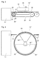
- Fig. 3 illustrates an embodiment of a treatment apparatus 10", wherein a cooling system 36" is integrated in one of the rollers 22 of the conveyer 18, preferably the roller 22 on the entry side 26.
- This roller 22 has a massive body made of a material with good heat conductivity, e.g. a metal, and includes a number of coolant passages 42 for circulating a refrigerant.
- the roller 22 is thereby cooled to a temperature below ambient temperature, and the substrate 20 is cooled by thermal contact with the roller 22.
- the top surface of the suction box 34 may be cooled with a refrigerant.
- a humidifier 44 is disposed above the sheet 12 in the stabilization zone 28 for increasing the moisture content of the air that is blown or drawn against the sheet, thereby to re-humidify the sheet while it is being flattened.
- Fig. 4 illustrates an embodiment of a treatment apparatus 10'" wherein the perforated substrate 20 forms the peripheral surface of a drum-type conveyer 18"'.
- a suction box 34'" is disposed in the top part of the drum conveyer, and a cooling system 36'" that may be configured analogous to any of the cooling systems 36 and 36' shown in Figs. 1 and 2 is disposed in the bottom part of the drum conveyer. Alternatively, the suction box 34"' may be cooled.
- the sheets 12 discharged from the image forming apparatus 14 are sucked against the surface of the substrate 20 and conveyed through the stabilization zone 28 until they are separated from the conveyer at the discharge roller 32. Since the diameter of the drum-type conveyer 18'" is large in comparison to the size of the sheets 12, a curvature that may be imposed on the sheets 12 in the stabilization zone 28 is so low that it is negligible in the subsequent handling of the sheets.
Landscapes
- Physics & Mathematics (AREA)
- General Physics & Mathematics (AREA)
- Delivering By Means Of Belts And Rollers (AREA)
- Control Or Security For Electrophotography (AREA)
Abstract
Description
- The invention relates to a combination of an image forming apparatus and an apparatus for treating media sheets after an image has been formed, the image forming apparatus comprising a processing stage causing the media sheets to be heated, the apparatus for treating the media sheets being disposed on a discharge side of the image forming apparatus and comprising an apparatus for treating media sheets, comprising an endless perforated conveying and support substrate arranged to convey the media sheets through a stabilization zone where the substrate has a limited curvature, and a suction device for applying a vacuum to the perforations of the substrate in the stabilization zone so as to suck the media sheets against the substrate.
- When media sheets such as sheets of paper, machine coated paper sheets or plastic film are processed in an image forming apparatus, for example, in which a liquid ink or toner is applied to one side of the sheets and/or the sheets are subjected to a heat treatment, e.g. for fusing a toner image on the sheets or drying and fixing an ink image on the sheets, the sheets tend to deform after they have been processed. The tendency to deform is particularly pronounced in case of sheets that bear a coating on one side.
-
US 6 467 410 B1 describes an apparatus of the type indicated above which may be used for treating the sheets after the image forming process in order to reduce the curls in the sheets. In this apparatus the deformations are at least partly eliminated by sucking the sheets, by means of vacuum pressure, against a substrate surface that is flat or curved only gently, so that the sheets adopt the flat or gently curved configuration of the substrate. - In conjunction with an image forming process in which the sheets are subjected to a heat treatment it is known, e.g. from
US 2011090279 A1 , to pass the heated sheets through a cooling zone where the temperature of the sheets is reduced again, e.g. by blowing cold air against the sheets or contacting them with a cooled substance. -
US 2002/071016 A1 andJP 2013 049567A - It is an object of the invention to provide an apparatus that permits to reduce the deformation tendency of the sheets more efficiently, especially, when the sheets have been heated in a preceding process.
- In order to achieve this object, the combination according to the invention has a cooling system arranged for actively cooling the media sheets while they are sucked against the substrate in the stabilization zone.
- By actively cooling the sheets in the very condition in which they are flattened by being sucked against the substrate surface, the flat configuration of the substrate surface is "frozen" in the sheet, so that the deformation tendency is reduced significantly.
- More specific optional features of the invention are indicated in the dependent claims.
- In a particularly preferred embodiment, the substrate is an endless conveyer arranged for conveying the sheets from an entry side of the stabilization zone to an exit side, and the cooling system is arranged for cooling the substrate on a return path from the exit side to the entry side. In this case, the heat capacity and heat conductivity of the substrate are used for cooling the sheets indirectly. The heated sheets transfer their heat to the substrate while they are sucked against the substrate in the stabilization zone, and then the temperature of the substrate is returned to ambient temperature or below ambient temperature in the cooling zone. Since the cooling zone is separated from the stabilization zone, the cooling system can act upon the substrate in a state in which the substrate is not covered by the media sheets and the cooling system does not interfere with the vacuum system in the stabilization zone.
- In an embodiment, the apparatus according to the present invention comprises a means for subjecting the sheets to moist air during cooling in the very condition in which they are flattened by being sucked against the substrate surface. In particular the apparatus may be provided with a more or less closed chamber encompassing at least the stabilization zone. The more or less closed chamber may be provided with moist air. In this embodiment, sheets that may be over dried by a prior heat treatment are rehydrated while being flattened by being sucked against the substrate surface to such an extent that the moisture level in the sheets is comparable to the moisture level of sheets prior to the heat treatment. In this way media deformation occurring after the cooling treatment in accordance with the present invention, due to moist absorption in the sheets, is prevented or at least mitigated.
- Embodiment examples will now be described in conjunction with the drawings, wherein:
- Fig. 1 - 4
- are schematic views of different embodiments of treatment apparatus according to the invention.
- As is shown in
Fig. 1 , anapparatus 10 for treatingmedia sheets 12 is disposed on a discharge side of animage forming apparatus 14 such as a printer or copier in which images are applied to the media sheets. In the example shown, theimage forming apparatus 14 comprises afuse station 16 where thesheets 12 are passed through a nip between heated rollers so as to heat the sheets in order to fuse the images formed thereon. Consequently, thesheets 12 have an elevated temperature when they are transferred onto thetreatment apparatus 10. - In the example shown in
Fig. 1 , theapparatus 10 comprises aconveyer 18 with aperforated substrate 20 in the form of an endless belt that is passed aroundrollers - The
sheets 12 discharged from theimage forming apparatus 14 enter into thetreatment apparatus 10 on anentry side 26 of astabilization zone 28 and are conveyed on a top section of thesubstrate 20 through thestabilization zone 28 to anexit side 30 thereof, where the sheets are passed on via adischarge roller 32. - A
suction box 34 is disposed underneath the top section of thesubstrate 20 in thestabilization zone 28 and applies a vacuum to the perforations of thesubstrate 20, so that thesheet 12 is forcefully sucked against the flat surface of thesubstrate 20 as has been indicated by arrows inFig. 1 . - The
substrate 20 is made of a material, e. g., a metal, having a high heat capacity and a high thermal conductivity, so that theheated sheets 12 that are held in close contact with thesubstrate 20 by the action of thesuction box 34 transfer most of their heat to thesubstrate 20 and are thereby cooled down to approximately ambient temperature. The combined effect of cooling thesheets 12 and simultaneously sucking them against the flat surface of thesubstrate 20 stabilizes thesheets 12 in a flat state and prevents the sheets from deforming, not only when they are held on thesubstrate 20 but also when they have left thetreatment apparatus 10. - The endless belt forming the
substrate 20 which has been heated through thermal contact with thesheets 12 in thestabilization zone 28 returns from theexit side 30 to theentry side 26 of the stabilization zone on the bottom side of theconveyer 18 and, on its return path, is cooled by means of acooling system 36. As a result, when thesubstrate 20 reaches again theentry side 26, its temperature has been restored to approximately ambient temperature, so that the substrate is ready again to absorb heat from thesheets 12. Thus, thesubstrate 20 serves as a heat transfer medium permitting to cool thesheets 12 indirectly by means of thecooling system 36. - In the example shown in
Fig. 1 , thecooling system 36 is formed by a portion of thesuction box 34 that has suction openings not only on the top side but also on the bottom side, so that ambient air is sucked in through the perforations of thebottom section substrate 20, as has also been symbolized by arrows inFig. 1 . Whereas the perforations of thesubstrate 20 in thestabilization zone 28 are blocked by theoverlying sheets 12, so that the suction box has no substantial cooling effect, the perforations in the bottom section of thesubstrate 20 are open, so that ambient air passes through these perforations into the suction box, with the result that thesubstrate 20 is efficiently cooled down to ambient temperature. -
Fig. 2 shows a treatment apparatus 10' according to a modified embodiment which differs from theapparatus 10 in that a different type of cooling system 36' is employed. In this case, thesuction box 34 has suction openings only on the top side facing thestabilization zone 28, whereas the bottom of the suction box is spaced apart from the lower section of thesubstrate 20. The cooling system 36' comprises ablower 38 and aheat exchange pipe 40 that is used for circulating a refrigerant through theblower 38 so that air that is blown out by the blower is cooled to a temperature below ambient temperature. The cold air is blown against thesubstrate 20 and passes through the perforations thereof, so that thesubstrate 20 is also cooled to a temperature below ambient temperature, resulting in an enhanced cooling effect on thesheets 12 that are conveyed through thestabilization zone 28. This treatment apparatus 10' may therefore be useful even in conjunction with an image forming apparatus 14' that employs an image forming process in which thesheets 12 are not subjected to a heat treatment, so that the sheets leave the image forming apparatus 14' at approximately ambient temperature. -
Fig. 3 illustrates an embodiment of atreatment apparatus 10", wherein acooling system 36" is integrated in one of therollers 22 of theconveyer 18, preferably theroller 22 on theentry side 26. Thisroller 22 has a massive body made of a material with good heat conductivity, e.g. a metal, and includes a number ofcoolant passages 42 for circulating a refrigerant. Theroller 22 is thereby cooled to a temperature below ambient temperature, and thesubstrate 20 is cooled by thermal contact with theroller 22. In an alternative embodiment (not shown) the top surface of thesuction box 34 may be cooled with a refrigerant. - A
humidifier 44 is disposed above thesheet 12 in thestabilization zone 28 for increasing the moisture content of the air that is blown or drawn against the sheet, thereby to re-humidify the sheet while it is being flattened. -
Fig. 4 illustrates an embodiment of a treatment apparatus 10'" wherein theperforated substrate 20 forms the peripheral surface of a drum-type conveyer 18"'. A suction box 34'" is disposed in the top part of the drum conveyer, and a cooling system 36'" that may be configured analogous to any of thecooling systems 36 and 36' shown inFigs. 1 and 2 is disposed in the bottom part of the drum conveyer. Alternatively, thesuction box 34"' may be cooled. - The
sheets 12 discharged from theimage forming apparatus 14 are sucked against the surface of thesubstrate 20 and conveyed through thestabilization zone 28 until they are separated from the conveyer at thedischarge roller 32. Since the diameter of the drum-type conveyer 18'" is large in comparison to the size of thesheets 12, a curvature that may be imposed on thesheets 12 in thestabilization zone 28 is so low that it is negligible in the subsequent handling of the sheets.
Claims (11)
- A combination of an image forming apparatus (14) and an apparatus for treating media sheets (12) after an image has been formed, the image forming apparatus comprising a processing stage (16) causing the media sheets to be heated, the apparatus for treating the media sheets being disposed on a discharge side of the image forming apparatus and comprising a perforated conveying and support substrate (20) arranged to convey the media sheets through a stabilization zone (28) where the substrate has a limited curvature, and a suction device (34; 34"') for applying a vacuum to the perforations of the substrate (20) in the stabilization zone (28) so as to suck the media sheets (12) against the substrate (20), characterized by a cooling system (36; 36'; 36"; 36"') arranged for actively cooling the media sheets (12) while they are sucked against the substrate (20) in the stabilization zone (28).
- The combination according to claim 1, wherein the stabilization zone (28) has an entry side (26) and an exit side (30), the substrate (20) forms part of an endless conveyer (18; 18"'), and the cooling system (36; 36'; 36"; 36"') is arranged to cool the substrate (20) in a return path from the exit side (30) to the entry side (26), the sheets (12) being cooled by thermal contact with the cooled substrate (20).
- The combination according to claim 2, wherein the cooling system (36) is formed by a suction box (34) arranged to suck air through the perforations of the substrate (20).
- The combination according to claim 2, wherein the cooling system (36) comprises a blower (38) arranged for blowing cold air against the substrate (20).
- The combination according to any of the preceding claims, wherein the substrate (20) is an endless belt.
- The combination according to claims 2 and 5, wherein the cooling system (36") is integrated in a roller (22) arranged to be in thermal contact with the substrate (20).
- The combination according to any of the claims 1 to 4, wherein the substrate (20) forms the surface of a rotating drum.
- The combination according to claim 1, wherein the apparatus further comprises a means for subjecting the sheets to moist air during cooling in the very condition in which they are flattened by being sucked against the substrate surface.
- A method of treating media sheets (12), comprising the steps of:- forming an image on the media sheets (12) by a process that involves heating of the media sheets; and then- conveying the media sheets on a perforated conveying and support substrate (20) through a stabilization zone (28) where the substrate has a limited curvature, and applying a vacuum to the perforations of the substrate (20) in the stabilization zone (28) so as to suck the media sheets (12) against the substrate (20),characterized by actively cooling the media sheets (12) while they are sucked against the substrate (20) in the stabilization zone (28).
- The method according to claim 9, wherein the substrate (20) forms part of an endless conveyer (18; 18"') on which the sheets (12) are conveyed from an entry side (26) to an exit side (30) of the stabilization zone (28), and the substrate (20) is cooled in a return path from the exit side (30) to the entry side (26), the sheets (12) being cooled by thermal contact with the cooled substrate (20).
- The method according to claim 9 or 10, wherein the sheets are subjected to moist air during cooling in the very condition in which they are flattened by being sucked against the substrate surface.
Priority Applications (1)
| Application Number | Priority Date | Filing Date | Title |
|---|---|---|---|
| EP20140189866 EP2868479A1 (en) | 2013-10-24 | 2014-10-22 | Apparatus for treating media sheets |
Applications Claiming Priority (2)
| Application Number | Priority Date | Filing Date | Title |
|---|---|---|---|
| EP13190119 | 2013-10-24 | ||
| EP20140189866 EP2868479A1 (en) | 2013-10-24 | 2014-10-22 | Apparatus for treating media sheets |
Publications (1)
| Publication Number | Publication Date |
|---|---|
| EP2868479A1 true EP2868479A1 (en) | 2015-05-06 |
Family
ID=49484188
Family Applications (1)
| Application Number | Title | Priority Date | Filing Date |
|---|---|---|---|
| EP20140189866 Withdrawn EP2868479A1 (en) | 2013-10-24 | 2014-10-22 | Apparatus for treating media sheets |
Country Status (2)
| Country | Link |
|---|---|
| US (1) | US20150117922A1 (en) |
| EP (1) | EP2868479A1 (en) |
Families Citing this family (4)
| Publication number | Priority date | Publication date | Assignee | Title |
|---|---|---|---|---|
| JP6682924B2 (en) * | 2016-03-09 | 2020-04-15 | コニカミノルタ株式会社 | Image forming device |
| ES2750073B2 (en) * | 2018-09-24 | 2021-05-11 | Asitec Ceram S L | SUPPORT BASE FOR CONVEYOR BELTS IN CONTINUOUS DIGITAL PRINTING MACHINES |
| DE102021123676A1 (en) | 2021-09-14 | 2023-03-16 | Koenig & Bauer Ag | Sheet-fed printing machine with a dryer for drying sheets printed by a non-impact printing device |
| DE102021123675A1 (en) | 2021-09-14 | 2023-03-16 | Koenig & Bauer Ag | Sheet-fed printing machine with a dryer for drying sheets printed by a non-impact printing device |
Citations (7)
| Publication number | Priority date | Publication date | Assignee | Title |
|---|---|---|---|---|
| US20020071016A1 (en) | 2000-12-08 | 2002-06-13 | Geoff Wotton | Anisotropic thermal conductivity on a heated platen |
| US6467410B1 (en) | 2000-01-18 | 2002-10-22 | Hewlett-Packard Co. | Method and apparatus for using a vacuum to reduce cockle in printers |
| JP2004130705A (en) * | 2002-10-11 | 2004-04-30 | Konica Minolta Holdings Inc | Inkjet printer |
| JP2004198863A (en) * | 2002-12-20 | 2004-07-15 | Kyocera Mita Corp | Image forming apparatus |
| US20110090279A1 (en) | 2009-10-15 | 2011-04-21 | Fujifilm Corporation | Image forming method |
| JP2013049567A (en) | 2011-08-31 | 2013-03-14 | Fujifilm Corp | Conveying apparatus and image forming apparatus |
| US20130177332A1 (en) * | 2012-01-11 | 2013-07-11 | Canon Kabushiki Kaisha | Image forming apparatus and cooling apparatus |
Family Cites Families (11)
| Publication number | Priority date | Publication date | Assignee | Title |
|---|---|---|---|---|
| DE4235667C1 (en) * | 1992-10-22 | 1994-01-05 | Siemens Nixdorf Inf Syst | Printer or copier with a cooling device for the recording medium |
| US6094560A (en) * | 1999-08-04 | 2000-07-25 | Xerox Corporation | Electrophotographic printing machine including a post-fusing substrate moisturizing and decurling device |
| US6584299B2 (en) * | 2001-09-28 | 2003-06-24 | Kabushiki Kaisha Toshiba | Image forming apparatus |
| JP2005255296A (en) * | 2004-03-10 | 2005-09-22 | Konica Minolta Business Technologies Inc | Image-forming device |
| JP2006220985A (en) * | 2005-02-10 | 2006-08-24 | Canon Inc | Image forming apparatus |
| JP2007121348A (en) * | 2005-10-25 | 2007-05-17 | Canon Inc | Image forming apparatus |
| JP2008120072A (en) * | 2006-10-20 | 2008-05-29 | Seiko Epson Corp | Inkjet printer |
| JP2012048058A (en) * | 2010-08-27 | 2012-03-08 | Canon Inc | Image forming apparatus |
| JP6053368B2 (en) * | 2012-07-26 | 2016-12-27 | キヤノン株式会社 | Sheet cooling apparatus and image forming apparatus |
| JP5975332B2 (en) * | 2012-08-10 | 2016-08-23 | 株式会社リコー | Cooling device and image forming apparatus |
| JP5825283B2 (en) * | 2013-03-27 | 2015-12-02 | 富士ゼロックス株式会社 | Image transfer apparatus and image forming apparatus |
-
2014
- 2014-10-22 EP EP20140189866 patent/EP2868479A1/en not_active Withdrawn
- 2014-10-23 US US14/522,125 patent/US20150117922A1/en not_active Abandoned
Patent Citations (7)
| Publication number | Priority date | Publication date | Assignee | Title |
|---|---|---|---|---|
| US6467410B1 (en) | 2000-01-18 | 2002-10-22 | Hewlett-Packard Co. | Method and apparatus for using a vacuum to reduce cockle in printers |
| US20020071016A1 (en) | 2000-12-08 | 2002-06-13 | Geoff Wotton | Anisotropic thermal conductivity on a heated platen |
| JP2004130705A (en) * | 2002-10-11 | 2004-04-30 | Konica Minolta Holdings Inc | Inkjet printer |
| JP2004198863A (en) * | 2002-12-20 | 2004-07-15 | Kyocera Mita Corp | Image forming apparatus |
| US20110090279A1 (en) | 2009-10-15 | 2011-04-21 | Fujifilm Corporation | Image forming method |
| JP2013049567A (en) | 2011-08-31 | 2013-03-14 | Fujifilm Corp | Conveying apparatus and image forming apparatus |
| US20130177332A1 (en) * | 2012-01-11 | 2013-07-11 | Canon Kabushiki Kaisha | Image forming apparatus and cooling apparatus |
Also Published As
| Publication number | Publication date |
|---|---|
| US20150117922A1 (en) | 2015-04-30 |
Similar Documents
| Publication | Publication Date | Title |
|---|---|---|
| EP2868479A1 (en) | Apparatus for treating media sheets | |
| JP2014021259A5 (en) | Image heating device | |
| US20210362516A1 (en) | Heating device | |
| JPH1115308A (en) | Image forming device | |
| JP6211461B2 (en) | Electrode material coating system with shutdown function layer | |
| JP2016112727A (en) | Pretreatment liquid coating/drying apparatus, printing system including the same, and printer | |
| KR102576893B1 (en) | Media handling between modules robust to paper curl | |
| US6634115B2 (en) | Conditioning device to change the moisture content of printing stock | |
| US20040265025A1 (en) | Thermally uniform sheet transport for printers | |
| JP6583707B2 (en) | Recording medium heating apparatus and recording medium drying system | |
| US6979802B2 (en) | Apparatus and method for thermally processing an imaging material employing a preheat chamber | |
| JPS58215651A (en) | Drying method of photosensitive material | |
| US7087861B2 (en) | Media entrance guide in a thermal processor | |
| JP2008504573A (en) | Heat treatment equipment with different roller spacing | |
| US7317468B2 (en) | Thermal processor employing drum and flatbed technologies | |
| JP2939042B2 (en) | Photosensitive material drying method and apparatus | |
| JP4703966B2 (en) | Method of carrying base material into heat treatment furnace and heat treatment furnace | |
| JP2942669B2 (en) | Drying device for automatic processor | |
| JP4780922B2 (en) | Heat treatment furnace and coating sheet manufacturing method | |
| JPH06289578A (en) | Apparatus for processing photosensitive material | |
| JPS6398683A (en) | Fixing device | |
| JP2005247484A (en) | Dehumidifier for recording sheet | |
| JP3039083U (en) | Conveyor roll with wrinkle prevention and meandering correction roll | |
| JP2023156013A5 (en) | ||
| JPH05289295A (en) | Photosensitive material drying device |
Legal Events
| Date | Code | Title | Description |
|---|---|---|---|
| PUAI | Public reference made under article 153(3) epc to a published international application that has entered the european phase |
Free format text: ORIGINAL CODE: 0009012 |
|
| 17P | Request for examination filed |
Effective date: 20141022 |
|
| AK | Designated contracting states |
Kind code of ref document: A1 Designated state(s): AL AT BE BG CH CY CZ DE DK EE ES FI FR GB GR HR HU IE IS IT LI LT LU LV MC MK MT NL NO PL PT RO RS SE SI SK SM TR |
|
| AX | Request for extension of the european patent |
Extension state: BA ME |
|
| R17P | Request for examination filed (corrected) |
Effective date: 20151106 |
|
| RBV | Designated contracting states (corrected) |
Designated state(s): AL AT BE BG CH CY CZ DE DK EE ES FI FR GB GR HR HU IE IS IT LI LT LU LV MC MK MT NL NO PL PT RO RS SE SI SK SM TR |
|
| STAA | Information on the status of an ep patent application or granted ep patent |
Free format text: STATUS: EXAMINATION IS IN PROGRESS |
|
| 17Q | First examination report despatched |
Effective date: 20161109 |
|
| STAA | Information on the status of an ep patent application or granted ep patent |
Free format text: STATUS: THE APPLICATION IS DEEMED TO BE WITHDRAWN |
|
| 18D | Application deemed to be withdrawn |
Effective date: 20170321 |