EP2868415A2 - Gear construction method and digital apparatus - Google Patents
Gear construction method and digital apparatus Download PDFInfo
- Publication number
- EP2868415A2 EP2868415A2 EP20140188546 EP14188546A EP2868415A2 EP 2868415 A2 EP2868415 A2 EP 2868415A2 EP 20140188546 EP20140188546 EP 20140188546 EP 14188546 A EP14188546 A EP 14188546A EP 2868415 A2 EP2868415 A2 EP 2868415A2
- Authority
- EP
- European Patent Office
- Prior art keywords
- curve
- gear
- involute
- digital
- tooth
- Prior art date
- Legal status (The legal status is an assumption and is not a legal conclusion. Google has not performed a legal analysis and makes no representation as to the accuracy of the status listed.)
- Withdrawn
Links
Images


Classifications
-
- G—PHYSICS
- G06—COMPUTING OR CALCULATING; COUNTING
- G06F—ELECTRIC DIGITAL DATA PROCESSING
- G06F30/00—Computer-aided design [CAD]
- G06F30/10—Geometric CAD
- G06F30/17—Mechanical parametric or variational design
-
- F—MECHANICAL ENGINEERING; LIGHTING; HEATING; WEAPONS; BLASTING
- F16—ENGINEERING ELEMENTS AND UNITS; GENERAL MEASURES FOR PRODUCING AND MAINTAINING EFFECTIVE FUNCTIONING OF MACHINES OR INSTALLATIONS; THERMAL INSULATION IN GENERAL
- F16H—GEARING
- F16H55/00—Elements with teeth or friction surfaces for conveying motion; Worms, pulleys or sheaves for gearing mechanisms
- F16H55/02—Toothed members; Worms
- F16H55/08—Profiling
- F16H55/0806—Involute profile
-
- B—PERFORMING OPERATIONS; TRANSPORTING
- B23—MACHINE TOOLS; METAL-WORKING NOT OTHERWISE PROVIDED FOR
- B23F—MAKING GEARS OR TOOTHED RACKS
- B23F17/00—Special methods or machines for making gear teeth, not covered by the preceding groups
-
- G—PHYSICS
- G06—COMPUTING OR CALCULATING; COUNTING
- G06T—IMAGE DATA PROCESSING OR GENERATION, IN GENERAL
- G06T17/00—Three-dimensional [3D] modelling for computer graphics
- G06T17/10—Constructive solid geometry [CSG] using solid primitives, e.g. cylinders, cubes
-
- F—MECHANICAL ENGINEERING; LIGHTING; HEATING; WEAPONS; BLASTING
- F16—ENGINEERING ELEMENTS AND UNITS; GENERAL MEASURES FOR PRODUCING AND MAINTAINING EFFECTIVE FUNCTIONING OF MACHINES OR INSTALLATIONS; THERMAL INSULATION IN GENERAL
- F16H—GEARING
- F16H57/00—General details of gearing
- F16H2057/0087—Computer aided design [CAD] specially adapted for gearing features; Analysis of gear systems
Definitions
- the present invention relates to a gear construction method and a digital apparatus.
- a point tracing process is generally adopted to form an involute of a tooth profile. That is, a series of points is generated in a modeling software according to the computational result externally, and then these points are fit to a curve to approximate the involute.
- a tooth profile generated by this modeling method is not accurate enough.
- this less accurate gear model is employed in subsequent simulation analysis or actual machining, the result of the analysis and the actual product machined are not desirable.
- gear parameters change each of the points needs to be regenerated and the curve fitting needs to be re-performed, resulting in a very tedious and time consuming modeling process.
- One object of the present invention is to provide a method capable of accurately constructing a gear.
- Another object of the present invention is to provide a method capable of constructing a gear more efficiently.
- Still another object of the present invention is to provide a digital apparatus associated with the above gear construction method.
- the method may include steps of: i). setting gear parameters and an XYZ coordinate system; ii) according to the gear parameters, creating a first curve associated with an involute of a tooth profile of a target tooth in an XZ plane, and creating a second curve associated with the involute of the tooth profile of the target tooth in a YZ plane; iii) combining the first curve with the second curve to form a third curve and projecting the third curve on an XY plane to obtain the involute of the target tooth; and iv) constructing the tooth profile of the target tooth by using the involute and forming a solid model of the entire gear.
- the first curve is combined with the second curve to form the third curve such that, if any imaginary plane perpendicular to a Z axis is intersected with the first curve at a first point, intersected with the second curve at a second point and intersected with the third curve at a third point, then the third point has an X coordinate corresponding to an X coordinate of the first point and a Y coordinate corresponding to a Y coordinate of the second point.
- the tooth profile of the target tooth may be created by using the involute and an addendum circle and a root circle of a gear.
- a sectional profile of the gear may be created by using the tooth profile of the target tooth; and the solid model of the gear may be formed by lofting the sectional profile of the gear along a straight line or a helix.
- the gear construction method may further include a step v): outputting the formed solid model of the gear for simulation analysis operations or actual machining operations.
- the gear construction method may be implemented by Pro/Engineer, UG or CATIA.
- the gear construction method may be implemented in a digital apparatus including at least one of a digital computing apparatus, a digital simulation apparatus and a digital machining apparatus.
- the present invention further relates to a digital apparatus including: a parameter input part for inputting gear parameters; a first curve forming part for creating a first curve associated with an involute of a tooth profile of a target tooth in an XZ plane according to the gear parameters; a second curve forming part for creating a second curve associated with the involute of the tooth profile of the target tooth in a YZ plane according to the gear parameters; a third curve formation for combining the first curve with the second curve to form a third curve; an involute forming part for projecting the third curve on an XY plane to obtain the involute of the target tooth; and a gear model constructing part for generating a gear model according to the involute of the target tooth.
- the first curve may be combined with the second curve to form the third curve such that, if any imaginary plane perpendicular to a Z axis is intersected with the first curve at a first point, intersected with the second curve at a second point and intersected with the third curve at a third point, then the third point has an X coordinate corresponding to an X coordinate of the first point and a Y coordinate corresponding to a Y coordinate of the second point.
- the gear model constructing part may further include a target tooth profile forming part for creating the tooth profile of the target tooth by using the involute and an addendum circle and a root circle of a gear.
- the gear model constructing part further includes: a gear profile forming part for forming a sectional profile of the gear by using the tooth profile of the target tooth; and a gear solid model forming part for forming a solid model of the gear by lofting the sectional profile of the gear along a straight line or a helix.
- the digital apparatus may further include a model output part for outputting a solid model of a gear to a simulation analysis apparatus or an actual machining apparatus.
- the digital apparatus may include at least one of a digital computing apparatus, a digital simulation apparatus and a digital machining apparatus.
- the accurate involute of the tooth profile can be formed in a simple manner and thereby the solid model can be formed accurately.
- expressions of the first curve and the second curve are correlated with predetermined gear parameters, the involute of the tooth profile can be changed and formed instantly when gear parameters are changed, thus greatly improving the efficiency of the gear modeling.
- the gear construction method according to the present invention is parameter-driven, the gear construction method according to the present invention can be conveniently embedded in the digital apparatus such as the digital simulation apparatus or the digital machining apparatus, and can be conveniently performed by a special integrated circuit, an individual logic circuit and/or an individual computing circuit or the like in these digital apparatuses.
- the simulation result of the digital simulation apparatus and machining accuracy of the digital machining apparatus as well as product accuracy can be improved.
- the first step setting gear parameters.
- gear parameters may be set: the number of teeth z, a module m, a tooth width B, a pressure angle ⁇ , a tooth root coefficient C*, an addendum coefficient ha*. It should be appreciated by those skilled in the art that the gear parameters are not limited to the above parameters; instead they may be chosen appropriately according to various construction methods of a gear model.
- the second step constructing a three-dimensional coordinate system XYZ in which the Z-axis direction is set to be an axial direction of a gear.
- the third step creating a base circle, an addendum circle and a root circle of the gear in an XY plane.
- r mxz/2.
- the fourth step creating a first curve associated with an involute of a tooth profile of a target tooth in an XZ plane, and creating a second curve associated with the involute of the tooth profile of the target tooth in a YZ plane.
- a reference straight line L may be created to be perpendicular to the XY plane, and then may be offset in a direction X to obtain the first curve 1.
- the second curve 2 may be obtained by offsetting the above reference straight line L in a direction Y.
- the fifth step combining the first curve with the second curve to form a third curve.
- a combined curve i.e., the third curve 3 as shown in Fig. 1
- a combined curve may be formed by using a COMBINE command in a modeling software such as CATIA to combine the first curve 1 with the second curve 2.
- any combining algorithm may be adopted such that, if any imaginary plane perpendicular to a Z axis is intersected with the first curve 1 at a first point, intersected with the second curve 2 at a second point and intersected with the third curve 3 at a third point, then the third point has an X coordinate corresponding to an X coordinate of the first point and a Y coordinate corresponding to a Y coordinate of the second point.
- the sixth step projecting the third curve on the XY plane to obtain the involute of the target tooth.
- a Z-coordinate of the third curve 3 may be set to 0 so as to obtain the involute 4.
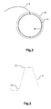
- Fig. 2 illustrates and a relationship between the involute 4 created in Fig. 1 , a base circle rb, an addendum circle rk and a root circle rf of a gear.
- the seventh step creating a tooth profile of the target tooth by using the involute and an addendum circle and a root circle of a gear.
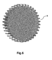
- the tooth profile 5 of the target tooth may be created by using the involute 4 and the addendum circle rk and the root circle rf of a gear according to any currently known manner, as shown in Fig 3 . Corners 5-1, 5-2 of the tooth profile 5 may be chamfered and/or filleted according to requirements so as to form a smoother curve.
- the eighth step creating a sectional profile of the gear by using the tooth profile of the target tooth.
- sectional profile 6 of the entire gear may be formed by annular arraying the tooth profile 5 of the target tooth.
- the ninth step forming a solid model of the entire gear by using the sectional profile of the gear.
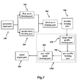
- a spatial curved surface 7 may be formed by lofting the sectional profile 6 of the gear along a straight line, and subsequently, two end surfaces of the spatial curved surface 7 may be closed to form a solid model 8 of the entire gear (a spur gear).
- a solid model of a helical gear may be formed by lofting the sectional profile 6 of the gear along a helix.
- the tenth step the solid model of the gear formed may be output for simulation analysis operations or actual machining operations.
- the above gear construction method may be implemented by a conventional modeling software such as Pro/Engineer, UG or CATIA, and it may also be implemented in a digital apparatus such as a digital computing apparatus, a digital simulation apparatus and a digital machining apparatus.
- the above gear construction method can be embedded in a digital simulation apparatus or a digital machining apparatus, so as to be performed by a processor, a special integrated circuit, or an individual logic circuit and/or an individual computing circuit in these digital apparatus.
- Fig. 7 exemplarily illustrates a portion of a digital apparatus implementing the above gear construction method. More specifically, the digital apparatus may include a parameter input part 100 for inputting gear parameters.
- the parameter input part 100 may be a keyboard, a mouse or a touch screen, or it may be an interface for communicating with other apparatus, etc.
- the digital apparatus may further include a first curve forming part 200 for creating a first curve 1 associated with an involute of a tooth profile of a target tooth in an XZ plane according to gear parameters.
- the digital apparatus may also include a second curve forming part 300 for creating a second curve 2 associated with the involute of the tooth profile of the target tooth in a YZ plane according to the gear parameters.
- the first curve forming part 200 and the second curve forming part 300 may create the first curve 1 and the second curve 2 by performing the corresponding process in the fourth step in the above method.
- the digital apparatus may further include a third curve forming part 400 for combining the first curve 1 with the second curve 2 to form a third curve 3.
- the third curve forming part 400 may form the third curve 3 by performing the corresponding process in the fifth step in the above method.
- the digital apparatus may further include an involute forming part 500 for projecting the third curve 3 on the XY plane to obtain the involute 4 of the target tooth.
- the involute forming part 500 may form the involute 4 by performing the corresponding process in the sixth step in the above method.
- the digital apparatus may further include a gear model constructing part 1000 for generating a gear model according to the involute 4 of the target tooth.
- the gear model constructing part 1000 may include a target tooth profile forming part 600 for creating a tooth profile of the target tooth by using the involute 4 and an addendum circle rk and a root circle rf of a gear.
- the target tooth profile forming part 600 may create the tooth profile 5 of the target tooth by performing the corresponding process in the seventh step in the above method.
- the gear model constructing part 1000 may further include: a gear profile forming part 700 for forming a sectional profile of the gear by using the tooth profile of the target tooth; and a gear solid model forming part 800 for forming a solid model of the gear by lofting the sectional profile of the gear along a straight line or a helix.
- the gear profile forming part 700 may create the sectional profile of the gear by performing the corresponding process in the eighth step in the above method.
- the gear solid model forming part 800 may create the solid model of the entire gear by performing the corresponding process in the ninth step in the above method.
- the digital apparatus may further include a model output part 900 for outputting the formed solid model of the gear to a simulation analysis apparatus or an actual machining apparatus.
- the model output part 900 may output the solid model of the gear by performing the corresponding process in the tenth step in the above method.
- the digital apparatus may include at least one of a digital computing apparatus, a digital simulation apparatus and a digital machining apparatus.
- a digital computing apparatus may include at least one of a digital computing apparatus, a digital simulation apparatus and a digital machining apparatus.
- at least one of the above various modules 100 to 1000 may be constructed to perform certain process by employing a processor and/or a special integrated circuit in the digital apparatus, or at least one of these modules 100 to 1000 may be constructed by an individual logic circuit and/or an individual computing circuit in the digital apparatus.
Landscapes
- Engineering & Computer Science (AREA)
- Physics & Mathematics (AREA)
- General Engineering & Computer Science (AREA)
- Geometry (AREA)
- Mechanical Engineering (AREA)
- Theoretical Computer Science (AREA)
- General Physics & Mathematics (AREA)
- Software Systems (AREA)
- Computer Graphics (AREA)
- Computational Mathematics (AREA)
- Mathematical Analysis (AREA)
- Mathematical Optimization (AREA)
- Pure & Applied Mathematics (AREA)
- Computer Hardware Design (AREA)
- Evolutionary Computation (AREA)
- Gears, Cams (AREA)
Abstract
Description
- The present invention relates to a gear construction method and a digital apparatus.
- The contents in this section only provide background information relating to the present invention which does not necessarily constitute the prior art.
- In a conventional gear modeling method, a point tracing process is generally adopted to form an involute of a tooth profile. That is, a series of points is generated in a modeling software according to the computational result externally, and then these points are fit to a curve to approximate the involute. A tooth profile generated by this modeling method is not accurate enough. When this less accurate gear model is employed in subsequent simulation analysis or actual machining, the result of the analysis and the actual product machined are not desirable. In addition, if gear parameters change, each of the points needs to be regenerated and the curve fitting needs to be re-performed, resulting in a very tedious and time consuming modeling process.
- One object of the present invention is to provide a method capable of accurately constructing a gear.
- Another object of the present invention is to provide a method capable of constructing a gear more efficiently.
- Still another object of the present invention is to provide a digital apparatus associated with the above gear construction method.
- One or more of the above objects may be achieved by a gear construction method. The method may include steps of: i). setting gear parameters and an XYZ coordinate system; ii) according to the gear parameters, creating a first curve associated with an involute of a tooth profile of a target tooth in an XZ plane, and creating a second curve associated with the involute of the tooth profile of the target tooth in a YZ plane; iii) combining the first curve with the second curve to form a third curve and projecting the third curve on an XY plane to obtain the involute of the target tooth; and iv) constructing the tooth profile of the target tooth by using the involute and forming a solid model of the entire gear.
- Preferably, in the step ii), the first curve may be obtained by offsetting a reference straight line perpendicular to the XY plane in a direction X, wherein the offset amount in the direction X is: x=rb×sin(t×π)-rb×cos(t×π)×(t×π), and the second curve may be obtained by offsetting the reference straight line in a direction Y, wherein the offset amount in the direction Y is: y=rb×cos(t×π)+rb×sin(t×π)×(t×π), in the above formulas, rb= (m×z/2)×cosα, wherein z is the number of teeth, m is a module, α is a pressure angle, and t is a variable.
- Preferably, in the step iii), the first curve is combined with the second curve to form the third curve such that, if any imaginary plane perpendicular to a Z axis is intersected with the first curve at a first point, intersected with the second curve at a second point and intersected with the third curve at a third point, then the third point has an X coordinate corresponding to an X coordinate of the first point and a Y coordinate corresponding to a Y coordinate of the second point.
- Preferably, in the step iv), the tooth profile of the target tooth may be created by using the involute and an addendum circle and a root circle of a gear.
- Preferably, in the step iv), a sectional profile of the gear may be created by using the tooth profile of the target tooth; and the solid model of the gear may be formed by lofting the sectional profile of the gear along a straight line or a helix.
- Preferably, the gear construction method may further include a step v): outputting the formed solid model of the gear for simulation analysis operations or actual machining operations.
- Preferably, the gear construction method may be implemented by Pro/Engineer, UG or CATIA.
- Preferably, the gear construction method may be implemented in a digital apparatus including at least one of a digital computing apparatus, a digital simulation apparatus and a digital machining apparatus.
- Preferably, the present invention further relates to a digital apparatus including: a parameter input part for inputting gear parameters; a first curve forming part for creating a first curve associated with an involute of a tooth profile of a target tooth in an XZ plane according to the gear parameters; a second curve forming part for creating a second curve associated with the involute of the tooth profile of the target tooth in a YZ plane according to the gear parameters; a third curve formation for combining the first curve with the second curve to form a third curve; an involute forming part for projecting the third curve on an XY plane to obtain the involute of the target tooth; and a gear model constructing part for generating a gear model according to the involute of the target tooth.
- Preferably, in the first curve forming part, the first curve may be obtained by offsetting a reference straight line perpendicular to the XY plane in an X direction, wherein the offset amount in the X direction is: x=rb×sin(t×π)-rb×cos(t×π)×(t×π), and in the above formula, rb= (m×z/2)×cosα, where z is the number of teeth, m is a module, α is a pressure angle, and t is a variable.
- Preferably, in the second curve forming part, the second curve may be obtained by offsetting a reference straight line perpendicular to the XY plane in a Y direction, wherein the offset amount in the Y direction is: y=rb×cos(t×π)+rb×sin(t×π)×(t×π), in the above formula, rb= (m×z/2)×cosα, wherein z is the number of teeth, m is a module, α is a pressure angle, and t is a variable.
- Preferably, in the third curve forming part, the first curve may be combined with the second curve to form the third curve such that, if any imaginary plane perpendicular to a Z axis is intersected with the first curve at a first point, intersected with the second curve at a second point and intersected with the third curve at a third point, then the third point has an X coordinate corresponding to an X coordinate of the first point and a Y coordinate corresponding to a Y coordinate of the second point.
- Preferably, the gear model constructing part may further include a target tooth profile forming part for creating the tooth profile of the target tooth by using the involute and an addendum circle and a root circle of a gear.
- Preferably, the gear model constructing part further includes: a gear profile forming part for forming a sectional profile of the gear by using the tooth profile of the target tooth; and a gear solid model forming part for forming a solid model of the gear by lofting the sectional profile of the gear along a straight line or a helix.
- Preferably, the digital apparatus may further include a model output part for outputting a solid model of a gear to a simulation analysis apparatus or an actual machining apparatus.
- Preferably, the digital apparatus may include at least one of a digital computing apparatus, a digital simulation apparatus and a digital machining apparatus.
- In the above gear construction method and digital apparatus according to the present invention, by creating the first curve associated with the involute of the tooth profile of the target tooth in the XZ plane, creating the second curve associated with the involute of the tooth profile of the target tooth in a YZ plane, as well as combining the first curve with the second curve and projecting the combined curve on an XY plane, the accurate involute of the tooth profile can be formed in a simple manner and thereby the solid model can be formed accurately. In addition, since expressions of the first curve and the second curve are correlated with predetermined gear parameters, the involute of the tooth profile can be changed and formed instantly when gear parameters are changed, thus greatly improving the efficiency of the gear modeling.
- Furthermore, since the gear construction method according to the present invention is parameter-driven, the gear construction method according to the present invention can be conveniently embedded in the digital apparatus such as the digital simulation apparatus or the digital machining apparatus, and can be conveniently performed by a special integrated circuit, an individual logic circuit and/or an individual computing circuit or the like in these digital apparatuses. Thus, the simulation result of the digital simulation apparatus and machining accuracy of the digital machining apparatus as well as product accuracy can be improved.
- Features and advantages of one or more embodiments of the present invention can be understood more readily with reference to the description in conjunction with the drawings in which:
-
Figure 1 is a schematic view illustrating an involute construction method according to an embodiment of the present invention; -
Figure 2 illustrates a relationship between an involute, a base circle, an addendum circle and a root circle of a gear according to the embodiment of the present invention; -
Figure 3 illustrates a tooth profile of a target tooth according to the embodiment of the present invention; -
Figure 4 illustrates a sectional profile of the entire gear according to the embodiment of the present invention; -
Figure 5 illustrates a model of partial surface of the gear according to the embodiment of the present invention; -
Figure 6 illustrates a solid model of the gear according to the embodiment of the present invention; and -
Figure 7 illustrates a construction of a portion of a digital apparatus according to an embodiment of the present invention. - The following description of the preferred embodiments is only illustrative rather than a limitation to the present invention and application or usage thereof. Throughout the figures, the like reference signs are used to indicate the like elements and thus the description of the like elements will not be repeated.
- The gear construction method according to the present invention will be described in detail hereinafter with reference to
Figs. 1 to 6 . - The first step: setting gear parameters.
- For example, the following gear parameters may be set: the number of teeth z, a module m, a tooth width B, a pressure angle α, a tooth root coefficient C*, an addendum coefficient ha*. It should be appreciated by those skilled in the art that the gear parameters are not limited to the above parameters; instead they may be chosen appropriately according to various construction methods of a gear model.
- The second step: constructing a three-dimensional coordinate system XYZ in which the Z-axis direction is set to be an axial direction of a gear.
- The third step: creating a base circle, an addendum circle and a root circle of the gear in an XY plane.
- For example, as shown in
Fig. 2 , the radius of the base circle rb may be rb=r×cosα, the radius of the addendum circle rk may be rk=r+m, and the radius of the root circle may be rf=r-1.25×m. In the above formula, r=mxz/2. - The fourth step: creating a first curve associated with an involute of a tooth profile of a target tooth in an XZ plane, and creating a second curve associated with the involute of the tooth profile of the target tooth in a YZ plane.
- More specifically, as shown in
Fig. 1 , a reference straight line L may be created to be perpendicular to the XY plane, and then may be offset in a direction X to obtain thefirst curve 1. In particular, an offset amount in the direction X may be: x=rb×sin(t×π)-rb×cos(t×π)×(t×π), in this formula, t is a variable, and for simplicity of the computation, t may have a value ranging [0, 1]. It should be appreciated by those skilled in the art that the abovefirst curve 1 may be obtained by using an OFFSET command in a modeling software such as CATIA to offset the reference straight line L in the direction X, or the abovefirst curve 1 may be created in the XZ plane by directly using the offset amount x=rb×sin(t×π)-rb×cos(t×π)×(t×π). For example, thefirst curve 1 may be created in the XZ plane by rewriting the above formula as a function of x(z)=rb×sin(z×π)-rb×cos(z×π)×(z×π). - Similarly, as shown in
Fig. 1 , thesecond curve 2 may be obtained by offsetting the above reference straight line L in a direction Y. In particular, an offset amount in the direction Y may be: y=rb×cos(t×π)+rb×sin(t×π)×(t×π), in this formula, t is a variable, and for simplicity of the computation, t may have a value ranging [0, 1]. It should be appreciated by those skilled in the art that the abovesecond curve 2 may be obtained by using an OFFSET command in a modeling software such as CATIA to offset the reference straight line L in the direction Y, or the abovesecond curve 2 may be created in the YZ plane by directly using the offset amount y=rb×cos(t×π)+rb×sin(t×π)×(t×π). For example, thesecond curve 2 may be created in the YZ plane by rewriting the above formula as a function of y(z)=rb×cos(z×π)+rb×sin(z×π)×(z×π). - The fifth step: combining the first curve with the second curve to form a third curve.
- More specifically, a combined curve, i.e., the
third curve 3 as shown inFig. 1 , may be formed by using a COMBINE command in a modeling software such as CATIA to combine thefirst curve 1 with thesecond curve 2. Or in other words, any combining algorithm may be adopted such that, if any imaginary plane perpendicular to a Z axis is intersected with thefirst curve 1 at a first point, intersected with thesecond curve 2 at a second point and intersected with thethird curve 3 at a third point, then the third point has an X coordinate corresponding to an X coordinate of the first point and a Y coordinate corresponding to a Y coordinate of the second point. - The sixth step: projecting the third curve on the XY plane to obtain the involute of the target tooth.
- More specifically, as shown in
Fig. 1 , a Z-coordinate of thethird curve 3 may be set to 0 so as to obtain theinvolute 4. In addition,Fig. 2 illustrates and a relationship between the involute 4 created inFig. 1 , a base circle rb, an addendum circle rk and a root circle rf of a gear. - The seventh step: creating a tooth profile of the target tooth by using the involute and an addendum circle and a root circle of a gear.
- More specifically, the
tooth profile 5 of the target tooth may be created by using theinvolute 4 and the addendum circle rk and the root circle rf of a gear according to any currently known manner, as shown inFig 3 . Corners 5-1, 5-2 of thetooth profile 5 may be chamfered and/or filleted according to requirements so as to form a smoother curve. - The eighth step: creating a sectional profile of the gear by using the tooth profile of the target tooth.
- For example, the
sectional profile 6 of the entire gear may be formed by annular arraying thetooth profile 5 of the target tooth. - The ninth step: forming a solid model of the entire gear by using the sectional profile of the gear.
- For example, a spatial
curved surface 7 may be formed by lofting thesectional profile 6 of the gear along a straight line, and subsequently, two end surfaces of the spatialcurved surface 7 may be closed to form asolid model 8 of the entire gear (a spur gear). In addition, it should also be appreciated by those skilled in the art, a solid model of a helical gear may be formed by lofting thesectional profile 6 of the gear along a helix. - The tenth step: the solid model of the gear formed may be output for simulation analysis operations or actual machining operations.
- It should be appreciated by those skilled in the art, the above gear construction method may be implemented by a conventional modeling software such as Pro/Engineer, UG or CATIA, and it may also be implemented in a digital apparatus such as a digital computing apparatus, a digital simulation apparatus and a digital machining apparatus. In particular, the above gear construction method can be embedded in a digital simulation apparatus or a digital machining apparatus, so as to be performed by a processor, a special integrated circuit, or an individual logic circuit and/or an individual computing circuit in these digital apparatus.
-
Fig. 7 exemplarily illustrates a portion of a digital apparatus implementing the above gear construction method. More specifically, the digital apparatus may include aparameter input part 100 for inputting gear parameters. Theparameter input part 100 may be a keyboard, a mouse or a touch screen, or it may be an interface for communicating with other apparatus, etc. - The digital apparatus may further include a first
curve forming part 200 for creating afirst curve 1 associated with an involute of a tooth profile of a target tooth in an XZ plane according to gear parameters. The digital apparatus may also include a secondcurve forming part 300 for creating asecond curve 2 associated with the involute of the tooth profile of the target tooth in a YZ plane according to the gear parameters. In particular, the firstcurve forming part 200 and the secondcurve forming part 300 may create thefirst curve 1 and thesecond curve 2 by performing the corresponding process in the fourth step in the above method. - The digital apparatus may further include a third
curve forming part 400 for combining thefirst curve 1 with thesecond curve 2 to form athird curve 3. In particular, the thirdcurve forming part 400 may form thethird curve 3 by performing the corresponding process in the fifth step in the above method. - The digital apparatus may further include an
involute forming part 500 for projecting thethird curve 3 on the XY plane to obtain theinvolute 4 of the target tooth. In particular, theinvolute forming part 500 may form theinvolute 4 by performing the corresponding process in the sixth step in the above method. - The digital apparatus may further include a gear
model constructing part 1000 for generating a gear model according to theinvolute 4 of the target tooth. Preferably, the gearmodel constructing part 1000 may include a target toothprofile forming part 600 for creating a tooth profile of the target tooth by using theinvolute 4 and an addendum circle rk and a root circle rf of a gear. In particular, the target toothprofile forming part 600 may create thetooth profile 5 of the target tooth by performing the corresponding process in the seventh step in the above method. The gearmodel constructing part 1000 may further include: a gearprofile forming part 700 for forming a sectional profile of the gear by using the tooth profile of the target tooth; and a gear solidmodel forming part 800 for forming a solid model of the gear by lofting the sectional profile of the gear along a straight line or a helix. In particular, the gearprofile forming part 700 may create the sectional profile of the gear by performing the corresponding process in the eighth step in the above method. The gear solidmodel forming part 800 may create the solid model of the entire gear by performing the corresponding process in the ninth step in the above method. - The digital apparatus may further include a
model output part 900 for outputting the formed solid model of the gear to a simulation analysis apparatus or an actual machining apparatus. Themodel output part 900 may output the solid model of the gear by performing the corresponding process in the tenth step in the above method. - It is to be noted that, the digital apparatus may include at least one of a digital computing apparatus, a digital simulation apparatus and a digital machining apparatus. For example, at least one of the above
various modules 100 to 1000 may be constructed to perform certain process by employing a processor and/or a special integrated circuit in the digital apparatus, or at least one of thesemodules 100 to 1000 may be constructed by an individual logic circuit and/or an individual computing circuit in the digital apparatus. - While various embodiments of the present invention have been described in detail herein, it should be understood that the present invention is not limited to the specific embodiments described in detail and illustrated herein, and those skilled in the art can also make other variants and modifications without departing from the principle and scope of the invention, and these variants and modifications should also be deemed to fall into the protective scope of the invention. Furthermore, all the elements described herein can be replaced by other technically equivalent elements.
Claims (16)
- A gear construction method, comprising steps of:i) setting gear parameters and an XYZ coordinate system;ii) according to the gear parameters, creating a first curve (1) associated with an involute of a tooth profile of a target tooth in an XZ plane, and creating a second curve (2) associated with the involute of the tooth profile of the target tooth in a YZ plane;iii) combining the first curve (1) with the second curve (2) to form a third curve (3) and projecting the third curve (3) on an XY plane to obtain the involute (4) of the target tooth; andiv) constructing the tooth profile of the target tooth by using the involute (4) and forming a solid model of the entire gear.
- The gear construction method according to claim 1, wherein in the step ii), the first curve (1) is obtained by offsetting a reference straight line (L) perpendicular to the XY plane in a direction X, wherein the offset amount in the direction X is: x=rb×sin(t×π)-rb×cos(t×π)×(t×π), and
the second curve (2) is obtained by offsetting the reference straight line (L) in a direction Y, wherein the offset amount in the direction Y is: y=rb×cos(t×π)+rb×sin(t×π)×(t×π),
in the above formulas, rb= (m×z/2)×cosα, wherein z is the number of teeth, m is a module, α is a pressure angle, and t is a variable. - The gear construction method according to claim 1, wherein in the step iii), the first curve (1) is combined with the second curve (2) to form the third curve (3) such that, if any imaginary plane perpendicular to a Z axis is intersected with the first curve (1) at a first point, intersected with the second curve (2) at a second point and intersected with the third curve (3) at a third point, then the third point has an X coordinate corresponding to an X coordinate of the first point and a Y coordinate corresponding to a Y coordinate of the second point.
- The gear construction method according to claim 1, wherein in the step iv), the tooth profile of the target tooth is created by using the involute (4) and an addendum circle (rk) and a root circle (rf) of a gear.
- The gear construction method according to claim 4, wherein in the step iv), a sectional profile of the gear is created by using the tooth profile of the target tooth; and the solid model of the gear is formed by lofting the sectional profile of the gear along a straight line or a helix.
- The gear construction method according to any one of claims 1 to 5, further comprising a step v): outputting the formed solid model of the gear for simulation analysis operations or actual machining operations.
- The gear construction method according to any one of claims 1 to 5, wherein the gear construction method is implemented by Pro/Engineer, UG or CATIA.
- The gear construction method according to any one of claims 1 to 5, wherein the gear construction method is implemented in a digital apparatus including at least one of a digital computing apparatus, a digital simulation apparatus and a digital machining apparatus.
- A digital apparatus, comprising:a parameter input part (100) for inputting gear parameters;a first curve forming part (200) for creating a first curve (1) associated with an involute of a tooth profile of a target tooth in an XZ plane according to the gear parameters;a second curve forming part (300) for creating a second curve (2) associated with the involute of the tooth profile of the target tooth in a YZ plane according to the gear parameters;a third curve forming part (400) for combining the first curve (1) with the second curve (2) to form a third curve (3);an involute forming part (500) for projecting the third curve (3) on an XY plane to obtain the involute (4) of the target tooth; anda gear model constructing part (1000) for generating a gear model according to the involute (4) of the target tooth.
- The digital apparatus according to claim 9, wherein in the first curve forming part (200), the first curve (1) is obtained by offsetting a reference straight line (L) perpendicular to the XY plane in an X direction, wherein the offset amount in the X direction is: x=rb×sin(t×π)-rb×cos(t×π)×(t×π), and in the above formula, rb= (m×z/2)×cosα, where z is the number of teeth, m is a module, α is a pressure angle, and t is a variable.
- The digital apparatus according to claim 9, wherein in the second curve forming part (300), the second curve (2) is obtained by offsetting a reference straight line (L) perpendicular to the XY plane in a Y direction, wherein the offset amount in the Y direction is: y=rb×cos(t×π)+rb×sin(t×π)×(t×π), wherein in the above formula, rb= (m×z/2)×cosα, wherein z is the number of teeth, m is a module, α is a pressure angle, and t is a variable.
- The digital apparatus according to claim 9, wherein in the third curve forming part (400), the first curve (1) is combined with the second curve (2) to form the third curve (3) such that, if any imaginary plane perpendicular to a Z axis is intersected with the first curve (1) at a first point, intersected with the second curve (2) at a second point and intersected with the third curve (3) at a third point, then the third point has an X coordinate corresponding to an X coordinate of the first point and a Y coordinate corresponding to a Y coordinate of the second point.
- The digital apparatus according to claim 9, wherein the gear model constructing part (1000) further comprises a target tooth profile forming part (600) for creating a tooth profile of the target tooth by using the involute (4) and an addendum circle (rk) and a root circle (rf) of a gear.
- The digital apparatus according to claim 13, wherein the gear model constructing part (1000) further comprises: a gear profile forming part (700) for forming a sectional profile of the gear by using the tooth profile of the target tooth; and a gear solid model forming part (800) for forming a solid model of the gear by lofting a sectional profile of the gear along a straight line or a helix.
- The digital apparatus according to any one of claims 9 to 14, further comprising a model output part (900) for outputting the formed solid model of a gear to a simulation analysis apparatus or an actual machining apparatus.
- The digital apparatus according to any one of claims 9 to 14, wherein the digital apparatus comprises at least one of a digital computing apparatus, a digital simulation apparatus and a digital machining apparatus.
Applications Claiming Priority (1)
| Application Number | Priority Date | Filing Date | Title |
|---|---|---|---|
| CN201310479015.6A CN104565285A (en) | 2013-10-14 | 2013-10-14 | Gear construction method and digital equipment |
Publications (2)
| Publication Number | Publication Date |
|---|---|
| EP2868415A2 true EP2868415A2 (en) | 2015-05-06 |
| EP2868415A3 EP2868415A3 (en) | 2016-06-01 |
Family
ID=51753009
Family Applications (1)
| Application Number | Title | Priority Date | Filing Date |
|---|---|---|---|
| EP14188546.7A Withdrawn EP2868415A3 (en) | 2013-10-14 | 2014-10-10 | Gear construction method and digital apparatus |
Country Status (3)
| Country | Link |
|---|---|
| US (1) | US20150106063A1 (en) |
| EP (1) | EP2868415A3 (en) |
| CN (1) | CN104565285A (en) |
Cited By (1)
| Publication number | Priority date | Publication date | Assignee | Title |
|---|---|---|---|---|
| CN109271711A (en) * | 2018-09-25 | 2019-01-25 | 重庆大学 | Finite element modeling method for carburized hardened gear considering uneven characteristics |
Families Citing this family (30)
| Publication number | Priority date | Publication date | Assignee | Title |
|---|---|---|---|---|
| EP3369017A4 (en) * | 2015-10-28 | 2019-06-12 | Sikorsky Aircraft Corporation | Protective cover and gear assembly |
| JP6746940B2 (en) * | 2016-02-16 | 2020-08-26 | 株式会社ジェイテクト | Apparatus and method for simulating tooth profile of gear, and apparatus and method for simulating blade surface of machining tool |
| CN106989157B (en) * | 2017-03-24 | 2019-06-14 | 北京工业大学 | Simulation method for double-sided meshing measurement of involute cylindrical gears based on kinematics |
| CN108763626B (en) * | 2018-04-13 | 2023-05-09 | 西安工业大学 | A precise modeling and assembly method of involute worm gear |
| CN108757887B (en) * | 2018-05-29 | 2021-08-31 | 中国航发常州兰翔机械有限责任公司 | A method for measuring and calculating parameters of involute gears and its application |
| CN109063326B (en) * | 2018-07-31 | 2022-06-14 | 中国第一汽车股份有限公司 | Gear accurate modeling method considering microscopic shape correction and actual machining errors |
| CN109483465B (en) * | 2018-11-23 | 2020-10-16 | 中国航发南方工业有限公司 | Component for disassembling engine turbine disc and preparation method thereof |
| CN109635478B (en) * | 2018-12-20 | 2023-03-31 | 广州华立科技职业学院 | Modeling method of worm gear |
| CN109858183A (en) * | 2019-03-07 | 2019-06-07 | 淮安福斯特液压科技有限公司 | A kind of determination method for gear pump flank profil molded line |
| CN109978993B (en) * | 2019-03-21 | 2023-04-25 | 中南大学 | Three-dimensional modeling method of involute helical gear |
| HUP1900107A1 (en) * | 2019-04-02 | 2020-10-28 | Maform Kft | Two-stage speed increaser gearing and gear train for a clockwork. |
| CN110162869B (en) * | 2019-05-16 | 2023-06-30 | 青岛数智船海科技有限公司 | Modeling method of involute gear |
| CN110765621B (en) * | 2019-10-28 | 2023-06-06 | 南京高精齿轮集团有限公司 | NX involute spline modeling method |
| CN110889194B (en) * | 2019-10-28 | 2023-06-06 | 南京高精齿轮集团有限公司 | Modeling method for NX involute deflection helical gear |
| CN111553039B (en) * | 2020-06-18 | 2023-02-24 | 西安航空学院 | A 3D Solid Modeling Method for Noncircular Gear Pairs with Cosine Tooth Profile |
| CN111539084B (en) * | 2020-06-18 | 2023-02-21 | 西安航空学院 | Involute tooth profile non-circular gear pair three-dimensional solid modeling method |
| CN112668112B (en) * | 2020-12-18 | 2023-02-21 | 西安法士特汽车传动有限公司 | Method for measuring and extracting basic parameters of tooth profile of involute cylindrical helical gear |
| CN113192180B (en) * | 2021-04-28 | 2022-08-09 | 山东科技大学 | Elliptic gear parameterization accurate modeling method based on gear shaping machining principle |
| CN114662266A (en) * | 2021-04-29 | 2022-06-24 | 长城汽车股份有限公司 | Spline modeling method and device, storage medium and electronic equipment |
| CN113283025B (en) * | 2021-05-11 | 2022-09-06 | 北京理工大学 | Involute tooth profile error modeling method containing system error |
| CN113566772B (en) * | 2021-07-19 | 2022-11-29 | 北京工业大学 | Local tooth surface positioning method based on coordinate measurement |
| CN114110136B (en) * | 2021-11-30 | 2024-01-26 | 重庆大学 | Design method of internal tooth profile of complex wave movable tooth reducer and two-stage reducer |
| CN114239162A (en) * | 2021-11-30 | 2022-03-25 | 江铃汽车股份有限公司 | Modeling method for water pump impeller of engine |
| CN114091210B (en) * | 2021-12-13 | 2024-05-10 | 山东大学 | Method for constructing generated grinding tooth surface distortion prediction model taking tooth profile modification into consideration |
| CN114719006B (en) * | 2022-04-06 | 2025-09-05 | 三峡大学 | Involute nonlinear displacement and tooth thickness variable gear transmission mechanism |
| CN114818378A (en) * | 2022-05-24 | 2022-07-29 | 江铃汽车股份有限公司 | Gear modeling method for generating involute tooth profile based on plane regular curve |
| CN115270324A (en) * | 2022-07-08 | 2022-11-01 | 东风商用车有限公司 | Cold extrusion gear tooth root modeling method |
| CN115859526B (en) * | 2022-12-19 | 2025-05-13 | 山东大学 | A parametric modeling method for modified helical gears |
| CN117972914B (en) * | 2023-11-30 | 2024-12-27 | 重庆大学 | Helical gear finite element grid generation method based on MATLAB and ABAQUS |
| CN118504063B (en) * | 2024-07-18 | 2024-10-01 | 兰州交通大学 | Performance evaluation and prediction model construction method for traction gear pairs of rail transit trains |
Family Cites Families (9)
| Publication number | Priority date | Publication date | Assignee | Title |
|---|---|---|---|---|
| JP3484879B2 (en) * | 1995-06-05 | 2004-01-06 | 株式会社豊田中央研究所 | Gear design method, gear and gear measurement method |
| DE112006001989B4 (en) * | 2005-07-28 | 2020-07-30 | Musashi Seimitsu Kogyo K.K. | Method of designing a gear using a CAD system |
| US7647210B2 (en) * | 2006-02-20 | 2010-01-12 | Ford Global Technologies, Llc | Parametric modeling method and system for conceptual vehicle design |
| US8610761B2 (en) * | 2009-11-09 | 2013-12-17 | Prohectionworks, Inc. | Systems and methods for optically projecting three-dimensional text, images and/or symbols onto three-dimensional objects |
| EP2383669B1 (en) * | 2010-04-02 | 2018-07-11 | Dassault Systèmes | Design of a part modeled by parallel geodesic curves |
| US9098123B2 (en) * | 2011-08-04 | 2015-08-04 | National Cheng Kung University | Moving trajectory generation method |
| US8967012B2 (en) * | 2011-08-17 | 2015-03-03 | Gm Global Technology Operations, Llc | Double involute pinion-face gear drive system |
| CN102829155B (en) * | 2012-09-10 | 2015-04-15 | 三一能源重工有限公司 | Method for shaping cylindrical gear |
| US20140092088A1 (en) * | 2012-10-03 | 2014-04-03 | Siemens Aktiengesellschaft | Providing a three-dimensional view that includes a plurality of systems engineering models |
-
2013
- 2013-10-14 CN CN201310479015.6A patent/CN104565285A/en active Pending
-
2014
- 2014-10-10 EP EP14188546.7A patent/EP2868415A3/en not_active Withdrawn
- 2014-10-13 US US14/512,758 patent/US20150106063A1/en not_active Abandoned
Non-Patent Citations (1)
| Title |
|---|
| None |
Cited By (1)
| Publication number | Priority date | Publication date | Assignee | Title |
|---|---|---|---|---|
| CN109271711A (en) * | 2018-09-25 | 2019-01-25 | 重庆大学 | Finite element modeling method for carburized hardened gear considering uneven characteristics |
Also Published As
| Publication number | Publication date |
|---|---|
| CN104565285A (en) | 2015-04-29 |
| EP2868415A3 (en) | 2016-06-01 |
| US20150106063A1 (en) | 2015-04-16 |
Similar Documents
| Publication | Publication Date | Title |
|---|---|---|
| US20150106063A1 (en) | Gear construction method and digital apparatus | |
| CN108447071B (en) | Gear tooth profile boundary extraction method based on meshing-pixel image edge tracking method | |
| US9524356B2 (en) | System and methods of generating a computer model of composite component | |
| CN110008594B (en) | A method for automatic modeling and assembly of finite element meshes of planetary transmission herringbone gears | |
| JP6746940B2 (en) | Apparatus and method for simulating tooth profile of gear, and apparatus and method for simulating blade surface of machining tool | |
| CN101393581A (en) | Simulation analysis method for high precision multi-tooth pair meshing contact of involute cylindrical gear | |
| CN104408241A (en) | Finite element grid automatic generation method of profiling cylindrical gear | |
| CN103065020A (en) | Method for applying CAD (computer-aided design) drawing to precision finger-type milling cutter for involute gears | |
| Li et al. | Tool path optimization in postprocessor of five-axis machine tools | |
| CN102262696B (en) | Modeling method for cylindrical gear of straight tooth or helical tooth | |
| CN102236738B (en) | Method for modelling straight-toothed or helical non-cylindrical gear | |
| Bodzás | Computer aided designing and modelling of spur gear pairs having normal and modified straight teeth | |
| CN108765558A (en) | A kind of tooth surface parameters acquisition methods based on spiral bevel gear milling flank of tooth three-dimensional modeling | |
| CN103454976B (en) | A kind of method applying rearmounted program reverse modeling | |
| Bodzás | Computer aided designing and modelling of x-zero gear drive | |
| CN109887079B (en) | Spiral bevel gear three-dimensional modeling method | |
| CN106294944A (en) | A kind of encoder knob orbital data modeling method | |
| CN115186493B (en) | Accurate modeling method for small modulus involute cylindrical gear | |
| CN102278453B (en) | Modeling method for straight cone gear | |
| CN101441673A (en) | Method and apparatus for drafting milling cutter corrugated teeth edge opening type line | |
| Zhang et al. | Research on virtual hobbing simulation and study of tooth surface accuracy of involute helical gears | |
| Jahanpour et al. | High-speed contouring control with NURBS-based C2 PH spline curves | |
| CN119026274B (en) | A method and system for automatically building a finite element model for bevel gear tooth surface contact analysis | |
| Zhu et al. | 3-D precise modeling of modified gear based on visual basic | |
| Shan et al. | Parametric design of straight bevel gears based on SolidWorks |
Legal Events
| Date | Code | Title | Description |
|---|---|---|---|
| PUAI | Public reference made under article 153(3) epc to a published international application that has entered the european phase |
Free format text: ORIGINAL CODE: 0009012 |
|
| 17P | Request for examination filed |
Effective date: 20141010 |
|
| AK | Designated contracting states |
Kind code of ref document: A2 Designated state(s): AL AT BE BG CH CY CZ DE DK EE ES FI FR GB GR HR HU IE IS IT LI LT LU LV MC MK MT NL NO PL PT RO RS SE SI SK SM TR |
|
| AX | Request for extension of the european patent |
Extension state: BA ME |
|
| RAP1 | Party data changed (applicant data changed or rights of an application transferred) |
Owner name: AIRBUS S.A.S. |
|
| PUAL | Search report despatched |
Free format text: ORIGINAL CODE: 0009013 |
|
| AK | Designated contracting states |
Kind code of ref document: A3 Designated state(s): AL AT BE BG CH CY CZ DE DK EE ES FI FR GB GR HR HU IE IS IT LI LT LU LV MC MK MT NL NO PL PT RO RS SE SI SK SM TR |
|
| AX | Request for extension of the european patent |
Extension state: BA ME |
|
| RIC1 | Information provided on ipc code assigned before grant |
Ipc: B23F 17/00 20060101ALI20160428BHEP Ipc: F16H 55/08 20060101AFI20160428BHEP |
|
| STAA | Information on the status of an ep patent application or granted ep patent |
Free format text: STATUS: REQUEST FOR EXAMINATION WAS MADE |
|
| R17P | Request for examination filed (corrected) |
Effective date: 20161109 |
|
| RBV | Designated contracting states (corrected) |
Designated state(s): AL AT BE BG CH CY CZ DE DK EE ES FI FR GB GR HR HU IE IS IT LI LT LU LV MC MK MT NL NO PL PT RO RS SE SI SK SM TR |
|
| STAA | Information on the status of an ep patent application or granted ep patent |
Free format text: STATUS: EXAMINATION IS IN PROGRESS |
|
| 17Q | First examination report despatched |
Effective date: 20170720 |
|
| STAA | Information on the status of an ep patent application or granted ep patent |
Free format text: STATUS: THE APPLICATION IS DEEMED TO BE WITHDRAWN |
|
| 18D | Application deemed to be withdrawn |
Effective date: 20171201 |