EP2868079B1 - Videodecodierer, verfahren und computerprogrammprodukt zur verarbeitung von kacheln von videodaten - Google Patents
Videodecodierer, verfahren und computerprogrammprodukt zur verarbeitung von kacheln von videodaten Download PDFInfo
- Publication number
- EP2868079B1 EP2868079B1 EP13724710.2A EP13724710A EP2868079B1 EP 2868079 B1 EP2868079 B1 EP 2868079B1 EP 13724710 A EP13724710 A EP 13724710A EP 2868079 B1 EP2868079 B1 EP 2868079B1
- Authority
- EP
- European Patent Office
- Prior art keywords
- tiles
- maximum number
- decoding
- tile
- decoder
- Prior art date
- Legal status (The legal status is an assumption and is not a legal conclusion. Google has not performed a legal analysis and makes no representation as to the accuracy of the status listed.)
- Active
Links
Images



Classifications
-
- H—ELECTRICITY
- H04—ELECTRIC COMMUNICATION TECHNIQUE
- H04N—PICTORIAL COMMUNICATION, e.g. TELEVISION
- H04N19/00—Methods or arrangements for coding, decoding, compressing or decompressing digital video signals
- H04N19/50—Methods or arrangements for coding, decoding, compressing or decompressing digital video signals using predictive coding
- H04N19/503—Methods or arrangements for coding, decoding, compressing or decompressing digital video signals using predictive coding involving temporal prediction
- H04N19/51—Motion estimation or motion compensation
-
- H—ELECTRICITY
- H04—ELECTRIC COMMUNICATION TECHNIQUE
- H04N—PICTORIAL COMMUNICATION, e.g. TELEVISION
- H04N19/00—Methods or arrangements for coding, decoding, compressing or decompressing digital video signals
- H04N19/10—Methods or arrangements for coding, decoding, compressing or decompressing digital video signals using adaptive coding
- H04N19/169—Methods or arrangements for coding, decoding, compressing or decompressing digital video signals using adaptive coding characterised by the coding unit, i.e. the structural portion or semantic portion of the video signal being the object or the subject of the adaptive coding
- H04N19/17—Methods or arrangements for coding, decoding, compressing or decompressing digital video signals using adaptive coding characterised by the coding unit, i.e. the structural portion or semantic portion of the video signal being the object or the subject of the adaptive coding the unit being an image region, e.g. an object
- H04N19/176—Methods or arrangements for coding, decoding, compressing or decompressing digital video signals using adaptive coding characterised by the coding unit, i.e. the structural portion or semantic portion of the video signal being the object or the subject of the adaptive coding the unit being an image region, e.g. an object the region being a block, e.g. a macroblock
-
- H—ELECTRICITY
- H04—ELECTRIC COMMUNICATION TECHNIQUE
- H04N—PICTORIAL COMMUNICATION, e.g. TELEVISION
- H04N19/00—Methods or arrangements for coding, decoding, compressing or decompressing digital video signals
- H04N19/42—Methods or arrangements for coding, decoding, compressing or decompressing digital video signals characterised by implementation details or hardware specially adapted for video compression or decompression, e.g. dedicated software implementation
- H04N19/436—Methods or arrangements for coding, decoding, compressing or decompressing digital video signals characterised by implementation details or hardware specially adapted for video compression or decompression, e.g. dedicated software implementation using parallelised computational arrangements
-
- H—ELECTRICITY
- H04—ELECTRIC COMMUNICATION TECHNIQUE
- H04N—PICTORIAL COMMUNICATION, e.g. TELEVISION
- H04N19/00—Methods or arrangements for coding, decoding, compressing or decompressing digital video signals
- H04N19/44—Decoders specially adapted therefor, e.g. video decoders which are asymmetric with respect to the encoder
-
- H—ELECTRICITY
- H04—ELECTRIC COMMUNICATION TECHNIQUE
- H04N—PICTORIAL COMMUNICATION, e.g. TELEVISION
- H04N19/00—Methods or arrangements for coding, decoding, compressing or decompressing digital video signals
- H04N19/60—Methods or arrangements for coding, decoding, compressing or decompressing digital video signals using transform coding
- H04N19/61—Methods or arrangements for coding, decoding, compressing or decompressing digital video signals using transform coding in combination with predictive coding
Definitions
- the present application relates to video encoders/decoders, methods and computer program product generally, and more particular to video encoders/decoders, methods and computer program product that process groups of adjacent blocks arranged in tiles.
- a video encoder is typically implemented by dividing each frame of original video data in blocks of pixels.
- these blocks would normally be of sized 16x16 and be referred to as macroblocks (MB).
- MB macroblocks
- the blocks would typically be larger (e.g. 64x64) and might be rectangular, for instance at frame boundaries.
- the blocks are processed and/or transmitted in raster scan order, i.e. from the top row of blocks to the bottom row of blocks, and from left to right within each row of blocks.
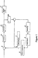
- a current frame as well as a prediction frame are input to a subtractor 9.
- the subtractor 9 is provided with input from an intra prediction processing path 3 and a motion compensation processing path 5, the selection of which is controlled by switch 7.
- Intra prediction processing is selected for finding similarities within the current image frame, and is thus referred to as "intra” prediction.
- Motion compensation has a temporal component and thus involves anslysis between successive frames that is referred to as "inter" prediction.
- the output of the switch 7 is subtracted from the pixels of the current frame in a subtractor 9, prior to being subjected to a two dimensional transform process 13.
- the transformed coefficients are then subjected to quantization in a quantizer 15 and then subject to an entropy encoder 17.
- Entropy encoding removes redundancies without losing information, and is referred to as a lossless encoding process.
- the encoded data is arranged in network packets via a packetizer, prior to be transmitted in a bit stream.
- the output of the quantizer 15 is also applied to an inverse transform and used for assisting in prediction processing.
- the output is applied to a deblocking filter 8, which suppresses some of the sharpness in the edges to improve clarity and better support prediction processing.
- the output of the deblocking filer 8 is applied to a frame memory 6, which holds the processed image pixel data in memory for use in subsequent motion processing.
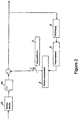
- each block can be described as follows (as indicated in Figure 2 ). After entropy decoding 22 (to produce the quantized transform coefficients) and two dimensional inverse transformation 26 on the quantized transform coefficient to provide a quantized version of the difference samples, the resultant image is reconstructed after adding the inter prediction and intra prediction data previously discussed.
- blocks can be divided into sub-blocks.
- the blocks are of fixed (square) size, while the sub-blocks can be of various e.g. (rectangular) shapes.
- the partitioning into sub-blocks will typically vary from one block to another.
- Inter prediction is typically achieved by deriving a set of motion vectors for each sub-block.
- the motion vectors define the spatial displacement between the original pixel data and the corresponding reconstructed pixel data in the previous frame.
- a motion vector may by used to efficiently convey the information about the feature that has changed position from one frame to the next.
- Intra prediction is typically achieved by deriving an intra direction mode for each sub-block.
- the intra direction mode defines the spatial displacement between the original pixel data and the previously reconstructed pixel data in the current frame.
- Both motion vectors and intra direction modes are encoded and transmitted to the decoder as side information for each sub-block.
- encoding of these parameters depends on the corresponding parameters of previously processed sub-blocks.
- entropy encoding typically, some form of adaptive entropy coding is used.
- the adaptation makes the entropy encoding/decoding for a sub-block dependent on previously processed sub-blocks.
- Entropy encoding is lossless encoding that reduces the number of bits that are needed to convey the information to a receiving site.
- deblocking filter (8 in Figure 2 ) across boundaries between blocks.
- a deblocking filter is applied to blocks in decoded video to improve visual quality and prediction performance by smoothing the sharp edges which can form between blocks when block coding techniques are used.
- the filter aims to improve the appearance of decoded pictures.
- the AVC/H.264 standard for video compression supports two mechanisms for parallel processing of blocks: Slices and Slice groups.
- a slice in AVC/H.264 is defined as a number of consecutive blocks in raster scan order.
- the use of slices is optional on the encoder side, and the information about slice boundaries is sent to the decoder in the network transportation layer or in the bit-stream as a unique bit pattern.
- slice design in AVC/H.264 is to allow transportation of compressed video over packet-based networks.
- one slice of compressed video data is transported as one packet.
- each slice is independently decodable. As recognized by the present inventor this requirement implies that all dependencies between blocks of different slices are broken.
- key parameters for the entire slice is transported in a slice header.
- Slice groups in AVC/H.264 define a partitioning of the blocks within a frame. The partitioning is signalled in the picture header. Blocks are processed and transmitted in raster-scan order within a slice group. Also, as recognized by the present inventor, since a slice can not span more than one slice group, dependencies are broken between slice groups in the same manner as between slices. As recognized by the present inventor, slice groups are different from "tiles" (as will be subsequently be discussed in detail) in at least two important aspects. First, with slice groups, blocks are transmitted in raster scan order within the slice group. Having to decode a bit stream that uses raster-scan order within a slice-group is a highly undesirable requirement for many decoders, especially those using a single core.
- slice groups can specify non-contiguous partitions of a frame (e.g. checkerboard pattern). Having to decode e.g. all the "white” blocks before all the "black” blocks of a checkerboard pattern or even more sophisticated patterns place an even worse burden on a decoder.
- ITU-T JCTVC-I0233 describes a proposal that claims to address tile problems.
- Chi et al., "Parallel Scalability and Efficiency of WPP and Tiles", 9th Meeting: Geneva 27 April - 7 May 2012, ITU-T JCTVC-I0520 describes a parallel scalability and efficiency analysis of the two main parallelization approaches being considered in HEVC.
- the invention is set out in the appended set of claims.
- the present inventor recognized limitations with conventional approaches for partitioning frames into groups of macroblocks. For example, although the dependency breaks that are defined for slices in AVC/H.264 are useful also for parallel processing, the definition of slices also has some disadvantages.
- the slice header implies a significant overhead that is not needed for parallel processing.
- the grouping of blocks into slices needs to comply with the raster-scan processing of blocks. In tum, this imposes an unnecessary an often undesired restriction on how a frame can be divided into independently decodable blocks.
- slice groups being able to make available many partitions
- Rectangular partitioning enables partitioning vertically (columns) as well as horizontally.
- the scheme has some undesired implications on the decoder.
- the decoder is forced to process the blocks in the same order as the encoder (i.e. raster-scan within a slice group). This might have severe implications on the decoder implementation as the decoder must be designed to handle almost arbitrary scan-orders.
- Another disadvantage of the slice groups in AVC/H.264 is that a maximum of 8 slice groups are allowed, and that each slice group consist of a separate slice including a slice header.
- a video decoder specification defines sequential block processing in raster scan order as the normal mode of operation. This ensures maximum compression efficiency by allowing dependency between neighbour blocks of the same frame to be exploited without restrictions. Typically, this implies that parameters for a given block depend on the same parameters in the blocks to the left and above. As described previously, this typically applies to reconstructed pixels for intra prediction, motion vector coding, intra direction mode coding, and adaptive entropy coding.
- a processing device designed for parallel processing comprises a number of cores (typically between 2 and 100), each core being able to encode/decode a subset of the blocks within a frame in parallel with other cores. This is best achieved if there are no dependencies between blocks being processed on different cores. Thus there is a trade-off between compression efficiency and the degree of parallel processing (number of blocks being processes simultaneously).
- the cores have access to shared memory where the previous reconstructed frames are stored. In those cases, dependencies between neighbouring blocks only needs to be broken for the current frame, allowing for unrestricted choice of motion vectors.
- one aspect of the present disclosure is that it minimizes the penalty on compression efficiency, while maximizing the degree and flexibility of parallel processing when encoding video frames.
- another aspect of the present disclosure is that it introduces tiles as a group of NxM adjacent blocks with dependency breaks at the tile boundaries.
- the definition of tiles is independent of the transmission order.
- the transmission order is assumed to follow the normal raster scan order within a frame (or slice group). This implies that an encoder/decoder can choose to perform all processing except bit-stream generation/parsing independently for each tile. Even if the encoder processes the frame by tiles, the decoder can choose to decode the frame in raster scan order.
- the present embodiment introduces the notion of "tiles" to exploit the two dimensional dependencies between blocks while also supporting the exploitation of multiple processors, if available in the encoder, to simultaneously perform encoding operations on multiple tiles.
- the partitioning of a frame into tiles is completely specified by the numbers N and M, eliminating the need for a slice header, which is a basic requirement in conventional slice processing.
- N and M are the height and width of a tile measured in number of blocks.
- the values of N and M are conveyed to the decoder in the sequence header or picture header resulting in negligible transmission bandwidth overhead.
- an alternative is to have a handshaking operation between the decoding device and encoding device, where the values of N and M are exchanged, as well as perhaps the processing capabilities of the decoder.
- N x M tile By making the dependency breaks in a N x M tile, the system exploits the possibility in images to create both vertical boundaries as well as horizontal boundaries that minimally disturbed correspondences between blocks. Moreover, the content of a particular series of images may be a natural landscapes that often have horizontal dependencies (such as horizons, etc.). On the other hand, imagery involving forests or other vertical oriented images may benefit more greatly by having a larger vertical dimension so that more blocks in the vertical dimension may be included as part of a common tile, thereby allowing for the exploitation of the dependencies between blocks in the vertical direction.
- the specification of the numbers N and M specifies dependency breaks at tile boundaries by implication.
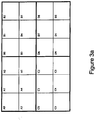
- Figure 3a shows an arrangement of 2 X 3 tiles (arbitrarily choosing 2 as being the vertical component and 3 being the horizontal component of a tile, but vice versa would also be an acceptable convention).
- Blocks having a same letter belong to a common tile and therefore are best suitable for being processed with one processing core. Therefore, supposing four processing cores are available, the "A" tile may be processed by one core while separate cores may handle the B, C and D tiles respectively, where all the processing is done in parallel.
- each tile of Figure 3a represent an ordering of macro blocks (or other blocks) within the tile.
- the first three blocks 0-2 are arranged in a horizontal row (in the raster scan direction), while a second row of blocks 3-5 are disposed in a row beneath the first row.
- the blocks are arranged in a two-dimensional group of blocks where the dependencies are broken at the vertical edge between tile A and tile B, and at the horizontal edge between tile A and tile C.
- Figure 3b shows the transmission order for the frame, which follows the raster-scan order.
- a tile reformatter is used at the decoder.
- a tile formatter is used to return the bits to proper block for each tile.
- the tile reformatter at the encoder conversion changes the tile-order (A0,A1,A2,A3,A4,A5,B0,B1,B2,..) as shown in Figure 3a to raster-scan order (A0,A1,A2,B0,B1,B2,A3, A4,...) as shown in Figure 3b .
- the tile formatter at the decoder performs a reordering operation from raster-scan order to tile-order.
- the decoder would have two options could either a) do nothing with the bitstream and decode the blocks in tile-order, or b) convert to raster-scan order and then decode the blocks in raster-scan order. Both options are alternative embodiments, although they place an extra processing burden on the decoder.
- the primary embodiment reflected in the drawings is to have the encoder place the bits in raster-scan order In turn, this minimizes the processing burden on the decoder and allows the decoder to either: a) do nothing with the bitstream and decode the blocks in raster scan order (i.e. no tile penalty), or b) convert from raster-scan order to tile-order and decode the blocks in tile-order. Therefore, if the encoder processes in tiles and assumes the burden of converting from tile-order to raster-scan order the decoder are compelled to do nothing except respect the dependency breaks at the tile boundaries.
- tiles are processed in parallel on different cores.
- Each core produces a string of compressed bits for that particular tile.
- the bits produced by different tiles/cores need to be reformatted. This is typically done on a single core.
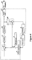
- a parallel processor embodiment is illustrated in Figure 4 , where the dashed line indicates modules that are processed in parallel on respective cores. Moreover, each core is assigned a processing task per tile (although there is no restriction on processing multiple tiles per core), and share memory resources to assist in sharing reference data for inter prediction between tiles and blocks.
- the frame memory resides in shared memory, while the tile reformatter is implemented on a single core. (Alternatively, the deblocking filter can run on a single core.)
- the subtractor 9, transform 13, quantization 15, inverse transform 26, blocking filter 8, frame memory 6, motion compensation 5, intraprediction 3, switch 7 and entropy coder 17 are all similar to that described earlier in Figure 1 .
- a tile reformatter 18 is used to retrieve and arrange bits from respective tiles so as to place them in raster scan order so that the bit stream sent from the encoder of Figure 4 would be in raster scan order.
- a decoder would optionally employ a corresponding tile formatter if it is configured to repackage the bits into the end by end tiles before decoding.
- a common core may perform all the functions, for example, of the transform 13, quantization 15, entropy coder 17, inverse transform 26, deblocking filter 8, motion compensation 5, switch 7 and interprediction 3.
- the tile reformatter 18 and frame memory 6 are available as a common resource amongst the different cores, each used for processing different tiles, the frame memory and tile reformatter 18 are not limited to use on a single core, but rather available for interfacing between the different cores.
- the subtractors and adders shown are implemented on a different core. The present arrangement of encoding functions on different cores is meant to be non-exhaustive.
- one aspect of having the arrangement in tiles is that there can be a correspondence between the tiles and the number of cores made available. Moreover, as discussed above, having multiple processor cores, provides available processing resources that may result in arranging a number of tiles to correspond with those cores.
- the decoder in the handshaking process with the encoder can specify whether the tile reformatter 18 shall be used or not (in a tile partitioning mode or not).
- the tile partitioning mode allows for the reception of bits read out from respective tiles, without reformatting, or reformatted so as to place the bits in the same order as would be provided in a raster-scan or as would be done with a conventional encoder.
- no handshaking is performed and the encoder and decoder always operate in the tile partitioning mode.
- tile reformatter encoder
- tile formatter decoder
- the tile reformatter 18 and tile formatter 25 have an internal by-pass capability for passing the bit-stream there through without manipulation.
- the tile reformatter 18 and tile formatter 25 are also used to show the two way communication between the encoder and decoder. This connection is merely exemplary because the encoder and decoder can exchange information (such as the values for N and M through sequence- or picture headers) through any one of a variety of communication interfaces.
- the bits representing the values N and M need not be reformatted in any way, and thus by-pass the reformatting and formatting functions in the tile reformatter 18 and tile formatter 25 respectively.
- other message data exchanged between the encoder and decoder use the tile reformatter and tile formatter as a communications interface, without bit reordering.
- Figure 5 is a block diagram of a decoder according to an embodiment that supports a tile portioning mode of operation, and includes parallel processing to assist in processing separate tiles.
- a dashed line indicates what decoding components are supported on a separate processing core, such that multiple cores may be used to simultaneously process tiles received from the encoder.
- the frame memory 6 is used as a common resource, similar to what is done at the encoder in Figure 4 .
- the tile formatter 25 initially receives the values N and M from the tile reformatter 18 from the encoder, although the tile reformatter does not perform any bit manipulation or reordering of these values.
- the tile formatter 25 recognizes the tile shapes for the data arriving from the incoming bit stream and ultimately allows the decoder components to perform a decoding operation based on the tile partitioning (and associated dependency breaks) introduced at the encoder. Moreover, the decoder breaks the dependencies in the current frame between blocks at tile boundaries as dictated by the values N and M. It should be noted that the encoder may provide multiple pairs of N and M, indicating that each tile, or at least multiple tiles, in a frame can have a different rectangular shape.
- the decoder can specify its wishes to the encoder for required/desired values of N and M or whether to use tile partitioning at all. This may be useful, for example, by the decoder informing the encoder that the decoder can support only a 720p30 display format if not in tile partitioning mode, but could support 1080p30 display format if used in a tile partitioning mode using tiles that are not larger than N x M.
- This two-way communication between the encoder and the decoder is represented by a double headed arrow at the tile formatter 25 in Figure 5 .
- tiles offer the advantage over conventional slices and slice groups in that no tile header is needed to identify tile boundaries. Moreover, there is no overhead required on a tile-by-tile or block-by-block basis to support the identification of tile boundaries. Instead, by specifying at first the shape of the tiles, or by reading the sequence or frame headers, the decoder has all the information it needs to identify tile boundaries based on the original specification of the values N and M. Also, the decoder has the option of using the tiles or not. In this way, the impact on the decoder is minimal since the decoder need not perform tile processing if it chooses not to. Also by allowing the encoder to specify different N x M shaped tiles, there is a large amount of flexibility with regard to arranging the number and size of the tiles to better support parallel processing and the speed with which encoding may be performed when multiple cores are available.
- tiles offer an advantage of decoupling the encoding process from the transmission order in which the bits are transmitted. This allows for better vertical intra prediction as opposed to conventional processes. Also, by using parallel tiles allows for better parallization for analysis since there is less constraint on tile shape and no header is required.
- an advantage of breaking dependency at column boundaries is that by dividing a frame vertically provides a smaller penalty on compression performance since a vertical boundary is shorter than a horizontal boundary when a 16:9 aspect ratio is the format for display, because motion generally tends to be performed in a horizontal direction.
- parallelization by columns reduces a delay since the data arrives one row at a time from the camera and all available cores can start to work immediately on a new row, as it arrives.
- partitioning a frame into tiles allows for the more efficient use of available cores to begin immediate processing of data provided from a camera, as compared with conventional approaches using slices or slice groups.
- Stitching is the collection of arbitrarily shaped rectangles which means that the change in spatial position of sub-pictures by manipulation in the compressed domain may be made possible.
- Tiles also allow for more efficient packetization into (almost) fixed-sized packets.
- a packetizer can assemble independent shelves of compressed data (one per column/row) into one packet without any backwards dependency to the encoding process. This helps provide autonomy in how data is transmitted from one location to the next for both transmission over separate communication paths, as well as processing independently at the decoder side.
- allowing for parallization by columns also provides for finer-grained parallelism and better load balancing amongst processing cores.
- Another advantage of using tiles is that by encoding by smaller widths provides the opportunity to reduce memory bandwidth and internal memory as composed to slice processing or slice groups. Moreover, the reduction in memory bandwidth and internal memory may be made available even if a single-core implementation is used.
- FIG. 6 is a flowchart showing a method for encoding frames using N x M tiles.
- the process begins in step S1, where a frame is portioned into blocks of pixels.
- the process then proceeds to step S3 where the blocks are arranged into N x M tiles.
- the tiles are grouped independent of the order of transmission of the blocks.
- the process then proceeds to step S5, where the values of N and M are transmitted to the receiving device in the sequence or picture header, but not in a slice or slice group header, recognizing that AVC/H.264 does not support anything but slices or slice groups.
- the tiles would not be compliant with AVC/H.264 because if the encoder decided to divide the frame into tiles, the decoder would not recognize the format.
- the encoder In a sequence header (before the first frame-which is part of the video stream, but after the call set up), the encoder would send the height and width of the tile. This way the decoder would know the size of the tiles. It should be noted that there can also be a pre-assignment of tile shape to type of frame, for example I (intra frame), B and P frames.
- each tile may then be encoded in parallel in step S7, where each tile is optionally encoded by a separate processing core.
- a single core can process more than one tile.
- devices with only one core can process all of the tiles.
- the process then proceeds to step S9 where the encoded tiles are transmitted to the receiving device.
- the transmission order can be in the raster scan order even though the tiles may have been encoded in a different order.
- the decoder decodes the tiles in step S11 with one or more cores. The process then repeats in step S13 for processing the next frame.
- processing tiles may present an implementation burden for single-core decoders. Accordingly, for adopting an industry-wide video compression standard that includes tile processing, some restrictions may be applied. Example restrictions are described below.
- tile restrictions apply (are mandatory), and other profiles where tile restrictions do not apply (are optional).
- decoders it would be possible for decoders to benefit from a flag, that is sent from the encoder in the sequence header, which informs the decoder whether certain tile restrictions (including those above) apply or not.
- An additional benefit of this flag is that it makes it easy to specify (in a standard text) whether the tile restrictions apply or not.
- the flag may be a single bit when signaling whether all tile restrictions are in place, or not.
- a multi-bit symbol may be used when there are multiple restrictions in place, and each bit within the multi-bit symbol signifies whether a particular restriction applies to the encoding and the bit stream.
- HEVC High efficiency video coding
- JCT-VC Joint Collaborative Team on Video Coding
- tile size restriction expressed in "High efficiency video coding (HEVC) text specification draft 7", cited above, that is independent of decoder capability level and therefore not included in the table above.
- the minimum tile width is 384 pixels, independent of the level.
- a limitation with defining tile size restrictions in this way is that it does not allow for encoder/bitstream flexibility in terms of the number of tiles it can send to a decoder claiming support for a certain capability level. For example, suppose there is a decoder that can decode level 4 (1080x1280 pixels). It is expected that this decoder would also be able to handle the same number of tiles (as per level 4 performance) for a lower resolution. However, "High efficiency video coding (HEVC) text specification draft 7", as cited above, does not allow for the encoder to send the same number of tiles for all resolutions.
- HEVC High efficiency video coding
- the decoder allows for the decoder to also specify its capability in terms of tile processing, such as maximum number of tiles vertically and maximum number of tiles horizontally.
- An advantage of augmenting the table with decoder tile number capability is that allows a decoder to more clearly make known how many tiles it can support.
- the encoder can send bitstreams at different resolutions but with the same number of tiles to a decoder claiming support to a certain decoder capability level.
- level 4 (1920 horizontal pixels by 1080 vertical pixels) and suppose level 4 (as per the augmented table) corresponds to a maximum of 5x5 tiles. Since the decoder has implicitly announced support for 5x5 tiles, through claiming support for level 4, an encoder can send a bitstream having 5x5 tiles at any resolution lower than 1080x1920.
- An additional benefit of adding two new columns to the table is that it is possible for the decoder through external signaling to announce that it can handle more tiles than given by the capability level it claims support for.
- a decoder can announce that it conforms to level 3.1 (1280x720), but it can additionally support the number of tiles corresponding to, for instance, level 6.2.
- An example revised table is shown below, where CPB is coded picture buffer; and DPB is decoded picture buffer.
- the encoder may know in advance the maximum number of vertical and horizontal tiles that a particular decoder can process. However, the decoder may also inform the encoder of its capability in advance of the encoder sending the bit stream. Once again, by allowing the decoder to inform the encoder in advance (either through signaling, or as a preregistered value known to the encoder), the encoder can send the same number of tiles, independent of the resolution of the image.
- Figure 7 illustrates a computer system 1201 upon which an embodiment of the present invention may be implemented.
- the computer system 1201 may be programmed to implement a computer based video conferencing endpoint that includes a video encoder or decoder for processing real time video images.
- the computer system 1201 includes a bus 1202 or other communication mechanism for communicating information, and a processor 1203 coupled with the bus 1202 for processing the information.
- the computer system 1201 also includes a main memory 1204, such as a random access memory (RAM) or other dynamic storage device (e.g., dynamic RAM (DRAM), static RAM (SRAM), and synchronous DRAM (SDRAM)), coupled to the bus 1202 for storing information and instructions to be executed by processor 1203.
- main memory 1204 may be used for storing temporary variables or other intermediate information during the execution of instructions by the processor 1203.
- the computer system 1201 further includes a read only memory (ROM) 1205 or other static storage device (e.g., programmable ROM (PROM), erasable PROM (EPROM), and electrically erasable PROM (EEPROM)) coupled to the bus 1202 for storing static information and instructions for the processor 1203.
- ROM read only memory
- PROM programmable ROM
- EPROM erasable PROM
- EEPROM electrically erasable PROM
- the computer system 1201 also includes a disk controller 1206 coupled to the bus 1202 to control one or more storage devices for storing information and instructions, such as a magnetic hard disk 1207, and a removable media drive 1208 (e.g., floppy disk drive, read-only compact disc drive, read/write compact disc drive, compact disc jukebox, tape drive, and removable magneto-optical drive).
- a removable media drive 1208 e.g., floppy disk drive, read-only compact disc drive, read/write compact disc drive, compact disc jukebox, tape drive, and removable magneto-optical drive.
- the storage devices may be added to the computer system 1201 using an appropriate device interface (e.g., small computer system interface (SCSI), integrated device electronics (IDE), enhanced-IDE (E-IDE), direct memory access (DMA), or ultra-DMA).
- SCSI small computer system interface
- IDE integrated device electronics
- E-IDE enhanced-IDE
- DMA direct memory access
- ultra-DMA ultra-DMA
- the computer system 1201 may also include special purpose logic devices (e.g., application specific integrated circuits (ASICs)) or configurable logic devices (e.g., simple programmable logic devices (SPLDs), complex programmable logic devices (CPLDs), and field programmable gate arrays (FPGAs)), that, in addition to microprocessors and digital signal processors may individually, or collectively, are types of processing circuitry.
- ASICs application specific integrated circuits
- SPLDs simple programmable logic devices
- CPLDs complex programmable logic devices
- FPGAs field programmable gate arrays
- the processing circuitry may be located in one device or distributed across multiple devices.
- the computer system 1201 may also include a display controller 1209 coupled to the bus 1202 to control a display 1210, such as a cathode ray tube (CRT), for displaying information to a computer user.
- the computer system includes input devices, such as a keyboard 1211 and a pointing device 1212, for interacting with a computer user and providing information to the processor 1203.
- the pointing device 1212 for example, may be a mouse, a trackball, or a pointing stick for communicating direction information and command selections to the processor 1203 and for controlling cursor movement on the display 1210.
- a printer may provide printed listings of data stored and/or generated by the computer system 1201.
- the computer system 1201 performs a portion or all of the processing steps of the invention in response to the processor 1203 executing one or more sequences of one or more instructions contained in a memory, such as the main memory 1204. Such instructions may be read into the main memory 1204 from another computer readable medium, such as a hard disk 1207 or a removable media drive 1208.
- processors in a multi-processing arrangement may also be employed to execute the sequences of instructions contained in main memory 1204.
- hard-wired circuitry may be used in place of or in combination with software instructions. Thus, embodiments are not limited to any specific combination of hardware circuitry and software.
- the computer system 1201 includes at least one computer readable medium or memory for holding instructions programmed according to the teachings of the invention and for containing data structures, tables, records, or other data described herein.
- Examples of computer readable media are compact discs, hard disks, floppy disks, tape, magneto-optical disks, PROMs (EPROM, EEPROM, flash EPROM), DRAM, SRAM, SDRAM, or any other magnetic medium, compact discs (e.g., CD-ROM), or any other optical medium, punch cards, paper tape, or other physical medium with patterns of holes, a carrier wave (described below), or any other medium from which a computer can read.
- the present invention includes software for controlling the computer system 1201, for driving a device or devices for implementing the invention, and for enabling the computer system 1201 to interact with a human user (e.g., print production personnel).
- software may include, but is not limited to, device drivers, operating systems, development tools, and applications software.
- Such computer readable media further includes the computer program product of the present invention for performing all or a portion (if processing is distributed) of the processing performed in implementing the invention.
- the computer code devices of the present invention may be any interpretable or executable code mechanism, including but not limited to scripts, interpretable programs, dynamic link libraries (DLLs), Java classes, and complete executable programs. Moreover, parts of the processing of the present invention may be distributed for better performance, reliability, and/or cost.
- Non-volatile media includes, for example, optical, magnetic disks, and magneto-optical disks, such as the hard disk 1207 or the removable media drive 1208.
- Volatile media includes dynamic memory, such as the main memory 1204.
- Transmission media includes coaxial cables, copper wire and fiber optics, including the wires that make up the bus 1202. Transmission media also may also take the form of acoustic or light waves, such as those generated during radio wave and infrared data communications.
- Various forms of computer readable media may be involved in carrying out one or more sequences of one or more instructions to processor 1203 for execution.
- the instructions may initially be carried on a magnetic disk of a remote computer.
- the remote computer can load the instructions for implementing all or a portion of the present invention remotely into a dynamic memory and send the instructions over a telephone line using a modem.
- a modem local to the computer system 1201 may receive the data on the telephone line and use an infrared transmitter to convert the data to an infrared signal.
- An infrared detector coupled to the bus 1202 can receive the data carried in the infrared signal and place the data on the bus 1202.
- the bus 1202 carries the data to the main memory 1204, from which the processor 1203 retrieves and executes the instructions.
- the instructions received by the main memory 1204 may optionally be stored on storage device 1207 or 1208 either before or after execution by processor 1203.
- the computer system 1201 also includes a communication interface 1213 coupled to the bus 1202.
- the communication interface 1213 provides a two-way data communication coupling to a network link 1214 that is connected to, for example, a local area network (LAN) 1215, or to another communications network 1216 such as the Internet.
- the communication interface 1213 may be a network interface card to attach to any packet switched LAN.
- the communication interface 1213 may be an asymmetrical digital subscriber line (ADSL) card, an integrated services digital network (ISDN) card or a modem to provide a data communication connection to a corresponding type of communications line.
- Wireless links may also be implemented.
- the communication interface 1213 sends and receives electrical, electromagnetic or optical signals that carry digital data streams representing various types of information.
- the network link 1214 typically provides data communication through one or more networks to other data devices.
- the network link 1214 may provide a connection to another computer through a local network 1215 (e.g., a LAN) or through equipment operated by a service provider, which provides communication services through a communications network 1216.
- the local network 1214 and the communications network 1216 use, for example, electrical, electromagnetic, or optical signals that carry digital data streams, and the associated physical layer (e.g., CAT 5 cable, coaxial cable, optical fiber, etc).
- the signals through the various networks and the signals on the network link 1214 and through the communication interface 1213, which carry the digital data to and from the computer system 1201 maybe implemented in baseband signals, or carrier wave based signals.
- the baseband signals convey the digital data as unmodulated electrical pulses that are descriptive of a stream of digital data bits, where the term "bits" is to be construed broadly to mean symbol, where each symbol conveys at least one or more information bits.
- the digital data may also be used to modulate a carrier wave, such as with amplitude, phase and/or frequency shift keyed signals that are propagated over a conductive media, or transmitted as electromagnetic waves through a propagation medium.
- the digital data may be sent as unmodulated baseband data through a "wired" communication channel and/or sent within a predetermined frequency band, different than baseband, by modulating a carrier wave.
- the computer system 1201 can transmit and receive data, including program code, through the network(s) 1215 and 1216, the network link 1214 and the communication interface 1213.
- the network link 1214 may provide a connection through a LAN 1215 to a mobile device 1217 such as a personal digital assistant (PDA) laptop computer, or cellular telephone.
- PDA personal digital assistant
Landscapes
- Engineering & Computer Science (AREA)
- Multimedia (AREA)
- Signal Processing (AREA)
- Computing Systems (AREA)
- Theoretical Computer Science (AREA)
- Compression Or Coding Systems Of Tv Signals (AREA)
Claims (12)
- Videodekodierer, umfassend:eine Schnittstelle, die zum Empfangen eines Bitstroms in Kachelreihenfolge in einem Videoeinzelbild, das in rechteckige Kacheln kodiert wurde, konfiguriert ist; undeine Verarbeitungsschaltungsanordnung, die zum Dekodieren des Videoeinzelbilds unter Anerkennung von Abhängigkeitsbrüchen an Kachelgrenzen konfiguriert ist, wobeidie rechteckigen Kacheln eine Ganzzahl von zweidimensionalen Pixelblöcken beinhalten,eine Kachelform von jeder der rechteckigen Kacheln von zweidimensionalen N x M-Pixelblöcken definiert wird,jeweilige Werte von N und M nicht für jede der rechteckigen Kacheln identisch sein müssen undInformationen bezüglich der Kachelform von einem Kodierer zum Dekodierer übermittelt werden, wobei der Dekodierer zum Bestimmen der Werte von N und M für jede Kachel anhand der Informationen konfiguriert ist, wobei die rechteckigen Kacheln Abhängigkeitsbrüche zwischen ihnen aufweisen, wobei die Werte von N und M in einer Sequenz oder einem Bildkopf übermittelt werden;wobei die Verarbeitungsschaltungsanordnung zum Verarbeiten einer maximalen Anzahl von horizontalen Kacheln und einer maximalen Anzahl von vertikalen Kacheln, die von einer Auflösung von Videoeinzelbildern unabhängig sind, konfiguriert ist, wobei die Auflösung von Videoeinzelbildern von einer Breite der Videoeinzelbilder und einer Höhe der Videoeinzelbilder bestimmt wird.
- Videodekodierungsverfahren, das Folgendes aufweist:Empfangen eines Bitstroms in Kachelreihenfolge in einem Videoeinzelbild, das in rechteckige Kacheln kodiert wurde;Vorbereiten zum Verarbeiten einer maximalen Anzahl von horizontalen Kacheln und vertikalen Kacheln, die von einer Auflösung von Videoeinzelbildern unabhängig sind, wobei die Auflösung der Videoeinzelbilder von einer Breite der Videoeinzelbilder und einer Höhe der Videoeinzelbilder bestimmt wird, wobei die maximale Anzahl von horizontalen Kacheln und die maximale Anzahl von vertikalen Kacheln einem Kodierer entweder dadurch, dass der Kodierer eine vorregistrierte Anzeige von Kacheln hat, oder dadurch, dass der Dekodierer den Kodierer im Voraus informiert, im Voraus bekannt sind; undDekodieren wenigstens eines Teils des Videoeinzelbilds mit einer Verarbeitungsschaltungsanordnung unter Anerkennung von Abhängigkeitsbrüchen an Kachelgrenzen, wobeidie rechteckigen Kacheln eine Ganzzahl von zweidimensionalen Pixelblöcken beinhalten,eine Kachelform der rechteckigen Kacheln von zweidimensionalen N x M-Pixelblöcken definiert wird,jeweilige Werte von N und M nicht für jede der rechteckigen Kacheln identisch sein müssen unddas Empfangen einer Anzeige das Empfangen von Informationen bezüglich der Kachelform beinhaltet und das Dekodieren das Bestimmen der Werte von N und M für jede Kachel anhand der Informationen beinhaltet und wobei die Werte von N und M in einer Sequenz oder einem Bildkopf übermittelt werden,die rechteckigen Kacheln zwischen ihnen Abhängigkeitsbrüche aufweisen.
- Videodekodierer nach Anspruch 1, wobei
die Verarbeitungsschaltungsanordnung zum Unterstützen des Dekodierens einer Auflösung von 720p mit einer maximalen Anzahl von vertikalen Kacheln von 3 und einer maximalen Anzahl von horizontalen Kacheln von 3 konfiguriert ist, wahlweise wobei
die Verarbeitungsschaltungsanordnung zum Unterstützen einer maximalen Bildgröße von 983,040 Abtastwerten konfiguriert ist. - Videodekodierer nach Anspruch 1 oder Dekodierungsverfahren nach Anspruch 2, wobei die Verarbeitungsschaltungsanordnung zum Unterstützen einer maximalen Anzahl von horizontalen Kacheln von 5 konfiguriert ist.
- Videodekodierer nach Anspruch 4 oder Dekodierungsverfahren nach Anspruch 2, wobei
die Verarbeitungsschaltungsanordnung zum Unterstützen des Dekodierens einer Auflösung von 1080p und des Dekodierens einer Auflösung von 1080p mit einer maximalen Anzahl von 4 vertikalen Kacheln und einer maximalen Anzahl von 5 horizontalen Kacheln konfiguriert ist. - Videodekodierer nach Anspruch 4 oder Dekodierungsverfahren nach Anspruch 2, wobei
die Verarbeitungsschaltungsanordnung zum Unterstützen einer maximalen Bitrate von 30.000 (1000 bits/s) und 5 vertikalen Kacheln konfiguriert ist oder wobei
die Verarbeitungsschaltungsanordnung zum Unterstützen einer maximalen Bitrate von 50.000 (1000 bits/s) und 5 vertikalen Kacheln konfiguriert ist. - Videodekodierer nach Anspruch 1 oder Dekodierungsverfahren nach Anspruch 2, wobei
die Verarbeitungsschaltungsanordnung Dekodieren mit einer maximalen Anzahl von 2 vertikalen Kacheln und einer maximalen Anzahl von 2 horizontalen Kacheln unterstützt oder wobei
die Verarbeitungsschaltungsanordnung Dekodieren mit einer maximalen Anzahl von 3 vertikalen Kacheln und einer maximalen Anzahl von 3 horizontalen Kacheln unterstützt oder wobei
die Verarbeitungsschaltungsanordnung Dekodieren mit einer maximalen Anzahl von 6 vertikalen Kacheln und einer maximalen Anzahl von 6 horizontalen Kacheln unterstützt oder wobei
die Verarbeitungsschaltungsanordnung Dekodieren mit einer maximalen Anzahl von 8 vertikalen Kacheln und einer maximalen Anzahl von 8 horizontalen Kacheln unterstützt. - Videodekodierungsverfahren nach Anspruch 2, wobei
das Dekodieren eine maximale Anzahl von vertikalen Kacheln von 3 und eine maximale Anzahl von horizontalen Kacheln von 3 dekodiert, wahlweise wobei
das Dekodieren eine maximale Bildgröße von 983.040 Abtastwerten unterstützt. - Nichtflüchtiges Computerprogrammprodukt, das mit einem Computerprogramm ausgestaltet ist, das bei Ausführung durch eine Verarbeitungsschaltungsanordnung ein Verfahren implementiert, wobei das Verfahren Folgendes aufweist:Empfangen eines Bitstroms in Kachelreihenfolge in einem Videoeinzelbild, das in rechteckige Kacheln kodiert wurde;Vorbereiten zum Verarbeiten einer maximalen Anzahl von horizontalen Kacheln und vertikalen Kacheln, die von einer Auflösung von Videoeinzelbildern unabhängig sind, wobei die Auflösung der Videoeinzelbilder von einer Breite der Videoeinzelbilder und einer Höhe der Videoeinzelbilder bestimmt wird, wobei die maximale Anzahl von horizontalen Kacheln und die maximale Anzahl von vertikalen Kacheln einem Kodierer entweder dadurch, dass der Kodierer eine vorregistrierte Anzeige von Kacheln hat, oder dadurch, dass der Dekodierer den Kodierer im Voraus informiert, im Voraus bekannt sind; undDekodieren wenigstens eines Teils des Videoeinzelbilds mit der Verarbeitungsschaltungsanordnung unter Anerkennung von Abhängigkeitsbrüchen an Kachelgrenzen, wobeidie rechteckigen Kacheln eine Ganzzahl von zweidimensionalen Pixelblöcken beinhalten,eine Kachelform der rechteckigen Kacheln von zweidimensionalen N x M-Pixelblöcken definiert wird,jeweilige Werte von N und M nicht für jede der rechteckigen Kacheln identisch sein müssen,das Empfangen einer Anzeige das Empfangen von Informationen bezüglich der Kachelform beinhaltet und das Dekodieren das Bestimmen der Werte von N und M für jede Kachel anhand der Informationen beinhaltet, wobei die rechteckigen Kacheln zwischen ihnen Abhängigkeitsbrüche aufweisen, wobei die Werte von N und M in einer Sequenz oder einem Bildkopf übermittelt werden.
- Nichtflüchtiges Computerprogrammprodukt nach Anspruch 9, wobei
das Dekodieren eine maximale Anzahl von vertikalen Kacheln von 3 und eine maximale Anzahl von horizontalen Kacheln von 3 unterstützt, wahlweise wobei
das Dekodieren eine maximale Bildgröße von 983,040 Abtastwerten unterstützt. - Nichtflüchtiges Computerprogrammprodukt nach Anspruch 10, wobei
das Dekodieren eine maximale Anzahl von horizontalen Kacheln von 5 unterstützt, wahlweise wobei
das Dekodieren das Dekodieren einer Auflösung von 1080p unterstützt oder wobei
das Dekodieren eine maximale Bitrate von 30.000 (1000 bits/s) und 5 vertikale Kacheln unterstützt. - Nichtflüchtiges Computerprogrammprodukt nach Anspruch 9, wobei
das Dekodieren das Dekodieren mit einer maximalen Anzahl von 2 vertikalen Kacheln und einer maximalen Anzahl von 2 horizontalen Kacheln unterstützt oder wobei
das Dekodieren das Dekodieren mit einer maximalen Anzahl of 3 vertikalen Kacheln und einer maximalen Anzahl von 3 horizontalen Kacheln unterstützt oder wobei
das Dekodieren das Dekodieren mit einer maximalen Anzahl von 6 vertikalen Kacheln und einer maximalen Anzahl von 6 horizontalen Kacheln unterstützt oder wobei
das Dekodieren das Dekodieren mit einer maximalen Anzahl von 8 vertikalen Kacheln und einer maximalen Anzahl von 8 horizontalen Kacheln unterstützt.
Applications Claiming Priority (3)
| Application Number | Priority Date | Filing Date | Title |
|---|---|---|---|
| US201261666011P | 2012-06-29 | 2012-06-29 | |
| US13/839,850 US9270994B2 (en) | 2012-06-29 | 2013-03-15 | Video encoder/decoder, method and computer program product that process tiles of video data |
| PCT/US2013/041597 WO2014003912A1 (en) | 2012-06-29 | 2013-05-17 | Video encoder/decoder, method and computer program product that process tiles of video data |
Publications (2)
| Publication Number | Publication Date |
|---|---|
| EP2868079A1 EP2868079A1 (de) | 2015-05-06 |
| EP2868079B1 true EP2868079B1 (de) | 2020-10-07 |
Family
ID=49778148
Family Applications (1)
| Application Number | Title | Priority Date | Filing Date |
|---|---|---|---|
| EP13724710.2A Active EP2868079B1 (de) | 2012-06-29 | 2013-05-17 | Videodecodierer, verfahren und computerprogrammprodukt zur verarbeitung von kacheln von videodaten |
Country Status (3)
| Country | Link |
|---|---|
| US (1) | US9270994B2 (de) |
| EP (1) | EP2868079B1 (de) |
| WO (1) | WO2014003912A1 (de) |
Families Citing this family (25)
| Publication number | Priority date | Publication date | Assignee | Title |
|---|---|---|---|---|
| CN104429075B (zh) * | 2012-07-09 | 2017-10-31 | 太阳专利托管公司 | 图像编码方法、图像解码方法、图像编码装置及图像解码装置 |
| US9485506B2 (en) | 2012-09-11 | 2016-11-01 | Texas Instruments Incorporated | Method and system for constraining slice header processing overhead in video coding |
| US10785482B2 (en) | 2012-09-24 | 2020-09-22 | Texas Instruments Incorporated | Method and system for constraining tile processing overhead in video coding |
| US9930353B2 (en) * | 2013-03-29 | 2018-03-27 | Sony Corporation | Image decoding device and method |
| JP6208993B2 (ja) * | 2013-06-28 | 2017-10-04 | ルネサスエレクトロニクス株式会社 | 画像復号装置及び画像復号装置の復号処理方法 |
| US11425395B2 (en) | 2013-08-20 | 2022-08-23 | Google Llc | Encoding and decoding using tiling |
| CN105659610A (zh) * | 2013-11-01 | 2016-06-08 | 索尼公司 | 图像处理设备和方法 |
| CN105874801B (zh) * | 2014-01-08 | 2019-11-08 | 索尼公司 | 解码设备和解码方法、以及编码设备和编码方法 |
| US10091530B2 (en) | 2014-10-01 | 2018-10-02 | Qualcomm Incorporated | Pipelined intra-prediction hardware architecture for video coding |
| US20160353133A1 (en) * | 2015-05-31 | 2016-12-01 | Cisco Technology, Inc. | Dynamic Dependency Breaking in Data Encoding |
| US10772247B2 (en) * | 2015-06-18 | 2020-09-08 | Fuji Corporation | Tape cutting processing apparatus and processing method |
| US10003807B2 (en) | 2015-06-22 | 2018-06-19 | Cisco Technology, Inc. | Block-based video coding using a mixture of square and rectangular blocks |
| US10009620B2 (en) | 2015-06-22 | 2018-06-26 | Cisco Technology, Inc. | Combined coding of split information and other block-level parameters for video coding/decoding |
| US10200707B2 (en) | 2015-10-29 | 2019-02-05 | Microsoft Technology Licensing, Llc | Video bit stream decoding |
| WO2016141777A2 (en) * | 2016-01-13 | 2016-09-15 | Shanghai Jing Peng Invest Management Co., Ltd. | Display device and pixel circuit thereof |
| KR102381373B1 (ko) | 2017-08-16 | 2022-03-31 | 삼성전자주식회사 | 비정형적 분할을 이용한 영상 부호화 방법 및 그 장치, 영상 복호화 방법 및 그 장치 |
| US20190139184A1 (en) * | 2018-08-01 | 2019-05-09 | Intel Corporation | Scalable media architecture for video processing or coding |
| US10812819B2 (en) * | 2018-10-07 | 2020-10-20 | Tencent America LLC | Method and apparatus for video coding |
| BR112021011413A2 (pt) | 2018-12-17 | 2021-08-31 | Huawei Technologies Co., Ltd. | Método e aparelho de codificação de vídeo |
| SI3903489T1 (sl) | 2018-12-27 | 2024-07-31 | Huawei Technologies Co., Ltd. | Izboljšave prilagodljivega razvrščanja ploščic pri kodiranju videa |
| KR20250171412A (ko) * | 2018-12-28 | 2025-12-08 | 후아웨이 테크놀러지 컴퍼니 리미티드 | 비디오 인코더, 비디오 디코더 및 대응하는 방법 |
| CN113632489B (zh) | 2019-03-06 | 2024-10-25 | 夏普株式会社 | 对视频数据进行解码的设备和方法 |
| CN110677692B (zh) * | 2019-09-27 | 2022-12-06 | 腾讯科技(深圳)有限公司 | 视频解码方法及装置、视频编码方法及装置 |
| GB2593776A (en) * | 2020-04-03 | 2021-10-06 | Sony Group Corp | Video data encoding and decoding |
| CN113015003B (zh) * | 2021-03-08 | 2022-11-25 | 展讯通信(上海)有限公司 | 视频帧缓存方法和设备 |
Family Cites Families (5)
| Publication number | Priority date | Publication date | Assignee | Title |
|---|---|---|---|---|
| US6263023B1 (en) | 1998-10-15 | 2001-07-17 | International Business Machines Corporation | High definition television decoder |
| JP2000244924A (ja) | 1999-02-19 | 2000-09-08 | Ricoh Co Ltd | データ圧縮伸長装置 |
| US20100232504A1 (en) | 2009-03-13 | 2010-09-16 | The State of Oregon acting by and through the State Board of Higher Education on behalf of the | Supporting region-of-interest cropping through constrained compression |
| US9300976B2 (en) | 2011-01-14 | 2016-03-29 | Cisco Technology, Inc. | Video encoder/decoder, method and computer program product that process tiles of video data |
| CA2854426A1 (en) * | 2011-11-08 | 2013-05-16 | Telefonaktiebolaget L M Ericsson (Publ) | Tile size in video coding |
-
2013
- 2013-03-15 US US13/839,850 patent/US9270994B2/en active Active
- 2013-05-17 EP EP13724710.2A patent/EP2868079B1/de active Active
- 2013-05-17 WO PCT/US2013/041597 patent/WO2014003912A1/en not_active Ceased
Non-Patent Citations (1)
| Title |
|---|
| None * |
Also Published As
| Publication number | Publication date |
|---|---|
| WO2014003912A1 (en) | 2014-01-03 |
| US9270994B2 (en) | 2016-02-23 |
| US20140003525A1 (en) | 2014-01-02 |
| EP2868079A1 (de) | 2015-05-06 |
Similar Documents
| Publication | Publication Date | Title |
|---|---|---|
| EP2868079B1 (de) | Videodecodierer, verfahren und computerprogrammprodukt zur verarbeitung von kacheln von videodaten | |
| EP2664148B1 (de) | Videokodierer/-dekodierer sowie verfahren und computerprogrammprodukt zur verarbeitung von anzeigeteilen von videodaten | |
| US20250016342A1 (en) | Video encoding method, video decoding method, and device using same | |
| EP3783889B1 (de) | Videodekodierungsgerät und videokodierungserät | |
| EP2659679B1 (de) | Verfahren für den selektiven abbruch der vorhersage in der videokodierung | |
| AU2013403224B2 (en) | Features of intra block copy prediction mode for video and image coding and decoding | |
| KR101628797B1 (ko) | Hevc에서 무손실 코딩의 개선된 인트라 예측 | |
| KR101847899B1 (ko) | 동영상 처리 방법 및 장치 | |
| EP4443877B1 (de) | Dekodierungsvorrichtung und kodiervorrichtung | |
| US11736737B2 (en) | Quantization parameter signaling in video processing | |
| EP4017006B9 (de) | Verfahren und vorrichtung zur signalisierung von bildinformationen sowie decodierungsverfahren und vorrichtung damit | |
| EP3811613B1 (de) | Flexible partitionierung in tiles | |
| KR101895295B1 (ko) | 동영상 처리 방법 및 장치 | |
| US20160080753A1 (en) | Method and apparatus for processing video signal | |
| EP3833026B1 (de) | Videodekodierungsvorrichtung, videodekodierungsverfahren und programm | |
| EP2665273B1 (de) | Videodekodierungsvorrichtung, videodekodierungsverfahren und programm dafür | |
| US20140321529A1 (en) | Video encoding and/or decoding method and video encoding and/or decoding apparatus | |
| WO2023235002A1 (en) | Systems and methods for partition-based predictions | |
| EP4635171A1 (de) | Systeme und verfahren zur keilbasierten prädiktionsmodussignalisierung |
Legal Events
| Date | Code | Title | Description |
|---|---|---|---|
| PUAI | Public reference made under article 153(3) epc to a published international application that has entered the european phase |
Free format text: ORIGINAL CODE: 0009012 |
|
| 17P | Request for examination filed |
Effective date: 20141128 |
|
| AK | Designated contracting states |
Kind code of ref document: A1 Designated state(s): AL AT BE BG CH CY CZ DE DK EE ES FI FR GB GR HR HU IE IS IT LI LT LU LV MC MK MT NL NO PL PT RO RS SE SI SK SM TR |
|
| AX | Request for extension of the european patent |
Extension state: BA ME |
|
| RIN1 | Information on inventor provided before grant (corrected) |
Inventor name: FULDSETH, ARILD |
|
| DAX | Request for extension of the european patent (deleted) | ||
| STAA | Information on the status of an ep patent application or granted ep patent |
Free format text: STATUS: EXAMINATION IS IN PROGRESS |
|
| 17Q | First examination report despatched |
Effective date: 20181018 |
|
| GRAP | Despatch of communication of intention to grant a patent |
Free format text: ORIGINAL CODE: EPIDOSNIGR1 |
|
| STAA | Information on the status of an ep patent application or granted ep patent |
Free format text: STATUS: GRANT OF PATENT IS INTENDED |
|
| INTG | Intention to grant announced |
Effective date: 20200504 |
|
| GRAS | Grant fee paid |
Free format text: ORIGINAL CODE: EPIDOSNIGR3 |
|
| GRAA | (expected) grant |
Free format text: ORIGINAL CODE: 0009210 |
|
| STAA | Information on the status of an ep patent application or granted ep patent |
Free format text: STATUS: THE PATENT HAS BEEN GRANTED |
|
| AK | Designated contracting states |
Kind code of ref document: B1 Designated state(s): AL AT BE BG CH CY CZ DE DK EE ES FI FR GB GR HR HU IE IS IT LI LT LU LV MC MK MT NL NO PL PT RO RS SE SI SK SM TR |
|
| REG | Reference to a national code |
Ref country code: GB Ref legal event code: FG4D |
|
| REG | Reference to a national code |
Ref country code: CH Ref legal event code: EP Ref country code: AT Ref legal event code: REF Ref document number: 1322439 Country of ref document: AT Kind code of ref document: T Effective date: 20201015 |
|
| REG | Reference to a national code |
Ref country code: DE Ref legal event code: R096 Ref document number: 602013073084 Country of ref document: DE |
|
| REG | Reference to a national code |
Ref country code: IE Ref legal event code: FG4D |
|
| REG | Reference to a national code |
Ref country code: NL Ref legal event code: MP Effective date: 20201007 |
|
| REG | Reference to a national code |
Ref country code: AT Ref legal event code: MK05 Ref document number: 1322439 Country of ref document: AT Kind code of ref document: T Effective date: 20201007 |
|
| PG25 | Lapsed in a contracting state [announced via postgrant information from national office to epo] |
Ref country code: NL Free format text: LAPSE BECAUSE OF FAILURE TO SUBMIT A TRANSLATION OF THE DESCRIPTION OR TO PAY THE FEE WITHIN THE PRESCRIBED TIME-LIMIT Effective date: 20201007 Ref country code: PT Free format text: LAPSE BECAUSE OF FAILURE TO SUBMIT A TRANSLATION OF THE DESCRIPTION OR TO PAY THE FEE WITHIN THE PRESCRIBED TIME-LIMIT Effective date: 20210208 Ref country code: NO Free format text: LAPSE BECAUSE OF FAILURE TO SUBMIT A TRANSLATION OF THE DESCRIPTION OR TO PAY THE FEE WITHIN THE PRESCRIBED TIME-LIMIT Effective date: 20210107 Ref country code: RS Free format text: LAPSE BECAUSE OF FAILURE TO SUBMIT A TRANSLATION OF THE DESCRIPTION OR TO PAY THE FEE WITHIN THE PRESCRIBED TIME-LIMIT Effective date: 20201007 Ref country code: FI Free format text: LAPSE BECAUSE OF FAILURE TO SUBMIT A TRANSLATION OF THE DESCRIPTION OR TO PAY THE FEE WITHIN THE PRESCRIBED TIME-LIMIT Effective date: 20201007 Ref country code: GR Free format text: LAPSE BECAUSE OF FAILURE TO SUBMIT A TRANSLATION OF THE DESCRIPTION OR TO PAY THE FEE WITHIN THE PRESCRIBED TIME-LIMIT Effective date: 20210108 |
|
| REG | Reference to a national code |
Ref country code: LT Ref legal event code: MG4D |
|
| PG25 | Lapsed in a contracting state [announced via postgrant information from national office to epo] |
Ref country code: BG Free format text: LAPSE BECAUSE OF FAILURE TO SUBMIT A TRANSLATION OF THE DESCRIPTION OR TO PAY THE FEE WITHIN THE PRESCRIBED TIME-LIMIT Effective date: 20210107 Ref country code: AT Free format text: LAPSE BECAUSE OF FAILURE TO SUBMIT A TRANSLATION OF THE DESCRIPTION OR TO PAY THE FEE WITHIN THE PRESCRIBED TIME-LIMIT Effective date: 20201007 Ref country code: ES Free format text: LAPSE BECAUSE OF FAILURE TO SUBMIT A TRANSLATION OF THE DESCRIPTION OR TO PAY THE FEE WITHIN THE PRESCRIBED TIME-LIMIT Effective date: 20201007 Ref country code: SE Free format text: LAPSE BECAUSE OF FAILURE TO SUBMIT A TRANSLATION OF THE DESCRIPTION OR TO PAY THE FEE WITHIN THE PRESCRIBED TIME-LIMIT Effective date: 20201007 Ref country code: IS Free format text: LAPSE BECAUSE OF FAILURE TO SUBMIT A TRANSLATION OF THE DESCRIPTION OR TO PAY THE FEE WITHIN THE PRESCRIBED TIME-LIMIT Effective date: 20210207 Ref country code: PL Free format text: LAPSE BECAUSE OF FAILURE TO SUBMIT A TRANSLATION OF THE DESCRIPTION OR TO PAY THE FEE WITHIN THE PRESCRIBED TIME-LIMIT Effective date: 20201007 Ref country code: LV Free format text: LAPSE BECAUSE OF FAILURE TO SUBMIT A TRANSLATION OF THE DESCRIPTION OR TO PAY THE FEE WITHIN THE PRESCRIBED TIME-LIMIT Effective date: 20201007 |
|
| PG25 | Lapsed in a contracting state [announced via postgrant information from national office to epo] |
Ref country code: HR Free format text: LAPSE BECAUSE OF FAILURE TO SUBMIT A TRANSLATION OF THE DESCRIPTION OR TO PAY THE FEE WITHIN THE PRESCRIBED TIME-LIMIT Effective date: 20201007 |
|
| REG | Reference to a national code |
Ref country code: DE Ref legal event code: R097 Ref document number: 602013073084 Country of ref document: DE |
|
| PG25 | Lapsed in a contracting state [announced via postgrant information from national office to epo] |
Ref country code: SM Free format text: LAPSE BECAUSE OF FAILURE TO SUBMIT A TRANSLATION OF THE DESCRIPTION OR TO PAY THE FEE WITHIN THE PRESCRIBED TIME-LIMIT Effective date: 20201007 Ref country code: CZ Free format text: LAPSE BECAUSE OF FAILURE TO SUBMIT A TRANSLATION OF THE DESCRIPTION OR TO PAY THE FEE WITHIN THE PRESCRIBED TIME-LIMIT Effective date: 20201007 Ref country code: EE Free format text: LAPSE BECAUSE OF FAILURE TO SUBMIT A TRANSLATION OF THE DESCRIPTION OR TO PAY THE FEE WITHIN THE PRESCRIBED TIME-LIMIT Effective date: 20201007 Ref country code: SK Free format text: LAPSE BECAUSE OF FAILURE TO SUBMIT A TRANSLATION OF THE DESCRIPTION OR TO PAY THE FEE WITHIN THE PRESCRIBED TIME-LIMIT Effective date: 20201007 Ref country code: RO Free format text: LAPSE BECAUSE OF FAILURE TO SUBMIT A TRANSLATION OF THE DESCRIPTION OR TO PAY THE FEE WITHIN THE PRESCRIBED TIME-LIMIT Effective date: 20201007 Ref country code: LT Free format text: LAPSE BECAUSE OF FAILURE TO SUBMIT A TRANSLATION OF THE DESCRIPTION OR TO PAY THE FEE WITHIN THE PRESCRIBED TIME-LIMIT Effective date: 20201007 |
|
| PLBE | No opposition filed within time limit |
Free format text: ORIGINAL CODE: 0009261 |
|
| STAA | Information on the status of an ep patent application or granted ep patent |
Free format text: STATUS: NO OPPOSITION FILED WITHIN TIME LIMIT |
|
| PG25 | Lapsed in a contracting state [announced via postgrant information from national office to epo] |
Ref country code: DK Free format text: LAPSE BECAUSE OF FAILURE TO SUBMIT A TRANSLATION OF THE DESCRIPTION OR TO PAY THE FEE WITHIN THE PRESCRIBED TIME-LIMIT Effective date: 20201007 |
|
| 26N | No opposition filed |
Effective date: 20210708 |
|
| PG25 | Lapsed in a contracting state [announced via postgrant information from national office to epo] |
Ref country code: IT Free format text: LAPSE BECAUSE OF FAILURE TO SUBMIT A TRANSLATION OF THE DESCRIPTION OR TO PAY THE FEE WITHIN THE PRESCRIBED TIME-LIMIT Effective date: 20201007 Ref country code: AL Free format text: LAPSE BECAUSE OF FAILURE TO SUBMIT A TRANSLATION OF THE DESCRIPTION OR TO PAY THE FEE WITHIN THE PRESCRIBED TIME-LIMIT Effective date: 20201007 |
|
| PG25 | Lapsed in a contracting state [announced via postgrant information from national office to epo] |
Ref country code: SI Free format text: LAPSE BECAUSE OF FAILURE TO SUBMIT A TRANSLATION OF THE DESCRIPTION OR TO PAY THE FEE WITHIN THE PRESCRIBED TIME-LIMIT Effective date: 20201007 |
|
| REG | Reference to a national code |
Ref country code: CH Ref legal event code: PL |
|
| PG25 | Lapsed in a contracting state [announced via postgrant information from national office to epo] |
Ref country code: LU Free format text: LAPSE BECAUSE OF NON-PAYMENT OF DUE FEES Effective date: 20210517 Ref country code: LI Free format text: LAPSE BECAUSE OF NON-PAYMENT OF DUE FEES Effective date: 20210531 Ref country code: MC Free format text: LAPSE BECAUSE OF FAILURE TO SUBMIT A TRANSLATION OF THE DESCRIPTION OR TO PAY THE FEE WITHIN THE PRESCRIBED TIME-LIMIT Effective date: 20201007 Ref country code: CH Free format text: LAPSE BECAUSE OF NON-PAYMENT OF DUE FEES Effective date: 20210531 |
|
| REG | Reference to a national code |
Ref country code: BE Ref legal event code: MM Effective date: 20210531 |
|
| PG25 | Lapsed in a contracting state [announced via postgrant information from national office to epo] |
Ref country code: IE Free format text: LAPSE BECAUSE OF NON-PAYMENT OF DUE FEES Effective date: 20210517 |
|
| PG25 | Lapsed in a contracting state [announced via postgrant information from national office to epo] |
Ref country code: IS Free format text: LAPSE BECAUSE OF FAILURE TO SUBMIT A TRANSLATION OF THE DESCRIPTION OR TO PAY THE FEE WITHIN THE PRESCRIBED TIME-LIMIT Effective date: 20210207 |
|
| PG25 | Lapsed in a contracting state [announced via postgrant information from national office to epo] |
Ref country code: BE Free format text: LAPSE BECAUSE OF NON-PAYMENT OF DUE FEES Effective date: 20210531 |
|
| PG25 | Lapsed in a contracting state [announced via postgrant information from national office to epo] |
Ref country code: HU Free format text: LAPSE BECAUSE OF FAILURE TO SUBMIT A TRANSLATION OF THE DESCRIPTION OR TO PAY THE FEE WITHIN THE PRESCRIBED TIME-LIMIT; INVALID AB INITIO Effective date: 20130517 |
|
| PG25 | Lapsed in a contracting state [announced via postgrant information from national office to epo] |
Ref country code: CY Free format text: LAPSE BECAUSE OF FAILURE TO SUBMIT A TRANSLATION OF THE DESCRIPTION OR TO PAY THE FEE WITHIN THE PRESCRIBED TIME-LIMIT Effective date: 20201007 |
|
| P01 | Opt-out of the competence of the unified patent court (upc) registered |
Effective date: 20230525 |
|
| PG25 | Lapsed in a contracting state [announced via postgrant information from national office to epo] |
Ref country code: MK Free format text: LAPSE BECAUSE OF FAILURE TO SUBMIT A TRANSLATION OF THE DESCRIPTION OR TO PAY THE FEE WITHIN THE PRESCRIBED TIME-LIMIT Effective date: 20201007 |
|
| PG25 | Lapsed in a contracting state [announced via postgrant information from national office to epo] |
Ref country code: MT Free format text: LAPSE BECAUSE OF FAILURE TO SUBMIT A TRANSLATION OF THE DESCRIPTION OR TO PAY THE FEE WITHIN THE PRESCRIBED TIME-LIMIT Effective date: 20201007 |
|
| PGFP | Annual fee paid to national office [announced via postgrant information from national office to epo] |
Ref country code: DE Payment date: 20250422 Year of fee payment: 13 |
|
| PGFP | Annual fee paid to national office [announced via postgrant information from national office to epo] |
Ref country code: FR Payment date: 20250505 Year of fee payment: 13 |
|
| PG25 | Lapsed in a contracting state [announced via postgrant information from national office to epo] |
Ref country code: TR Free format text: LAPSE BECAUSE OF FAILURE TO SUBMIT A TRANSLATION OF THE DESCRIPTION OR TO PAY THE FEE WITHIN THE PRESCRIBED TIME-LIMIT Effective date: 20201007 |
|
| PGFP | Annual fee paid to national office [announced via postgrant information from national office to epo] |
Ref country code: GB Payment date: 20260313 Year of fee payment: 14 |