EP2867664B1 - Verfahren und vorrichtung zur akustischen bewertung von fluidrohrleitungen - Google Patents
Verfahren und vorrichtung zur akustischen bewertung von fluidrohrleitungen Download PDFInfo
- Publication number
- EP2867664B1 EP2867664B1 EP13744858.5A EP13744858A EP2867664B1 EP 2867664 B1 EP2867664 B1 EP 2867664B1 EP 13744858 A EP13744858 A EP 13744858A EP 2867664 B1 EP2867664 B1 EP 2867664B1
- Authority
- EP
- European Patent Office
- Prior art keywords
- wideband acoustic
- fluid conduit
- wideband
- khz
- acoustic signal
- Prior art date
- Legal status (The legal status is an assumption and is not a legal conclusion. Google has not performed a legal analysis and makes no representation as to the accuracy of the status listed.)
- Active
Links
Images



Classifications
-
- G—PHYSICS
- G01—MEASURING; TESTING
- G01N—INVESTIGATING OR ANALYSING MATERIALS BY DETERMINING THEIR CHEMICAL OR PHYSICAL PROPERTIES
- G01N29/00—Investigating or analysing materials by the use of ultrasonic, sonic or infrasonic waves; Visualisation of the interior of objects by transmitting ultrasonic or sonic waves through the object
- G01N29/22—Details, e.g. general constructional or apparatus details
- G01N29/24—Probes
-
- G—PHYSICS
- G01—MEASURING; TESTING
- G01N—INVESTIGATING OR ANALYSING MATERIALS BY DETERMINING THEIR CHEMICAL OR PHYSICAL PROPERTIES
- G01N29/00—Investigating or analysing materials by the use of ultrasonic, sonic or infrasonic waves; Visualisation of the interior of objects by transmitting ultrasonic or sonic waves through the object
- G01N29/04—Analysing solids
- G01N29/043—Analysing solids in the interior, e.g. by shear waves
-
- G—PHYSICS
- G01—MEASURING; TESTING
- G01N—INVESTIGATING OR ANALYSING MATERIALS BY DETERMINING THEIR CHEMICAL OR PHYSICAL PROPERTIES
- G01N29/00—Investigating or analysing materials by the use of ultrasonic, sonic or infrasonic waves; Visualisation of the interior of objects by transmitting ultrasonic or sonic waves through the object
- G01N29/22—Details, e.g. general constructional or apparatus details
- G01N29/26—Arrangements for orientation or scanning by relative movement of the head and the sensor
- G01N29/265—Arrangements for orientation or scanning by relative movement of the head and the sensor by moving the sensor relative to a stationary material
-
- G—PHYSICS
- G01—MEASURING; TESTING
- G01N—INVESTIGATING OR ANALYSING MATERIALS BY DETERMINING THEIR CHEMICAL OR PHYSICAL PROPERTIES
- G01N29/00—Investigating or analysing materials by the use of ultrasonic, sonic or infrasonic waves; Visualisation of the interior of objects by transmitting ultrasonic or sonic waves through the object
- G01N29/34—Generating the ultrasonic, sonic or infrasonic waves, e.g. electronic circuits specially adapted therefor
- G01N29/341—Generating the ultrasonic, sonic or infrasonic waves, e.g. electronic circuits specially adapted therefor with time characteristics
- G01N29/343—Generating the ultrasonic, sonic or infrasonic waves, e.g. electronic circuits specially adapted therefor with time characteristics pulse waves, e.g. particular sequence of pulses, bursts
-
- G—PHYSICS
- G01—MEASURING; TESTING
- G01N—INVESTIGATING OR ANALYSING MATERIALS BY DETERMINING THEIR CHEMICAL OR PHYSICAL PROPERTIES
- G01N29/00—Investigating or analysing materials by the use of ultrasonic, sonic or infrasonic waves; Visualisation of the interior of objects by transmitting ultrasonic or sonic waves through the object
- G01N29/34—Generating the ultrasonic, sonic or infrasonic waves, e.g. electronic circuits specially adapted therefor
- G01N29/348—Generating the ultrasonic, sonic or infrasonic waves, e.g. electronic circuits specially adapted therefor with frequency characteristics, e.g. single frequency signals, chirp signals
-
- G—PHYSICS
- G01—MEASURING; TESTING
- G01N—INVESTIGATING OR ANALYSING MATERIALS BY DETERMINING THEIR CHEMICAL OR PHYSICAL PROPERTIES
- G01N29/00—Investigating or analysing materials by the use of ultrasonic, sonic or infrasonic waves; Visualisation of the interior of objects by transmitting ultrasonic or sonic waves through the object
- G01N29/36—Detecting the response signal, e.g. electronic circuits specially adapted therefor
- G01N29/42—Detecting the response signal, e.g. electronic circuits specially adapted therefor by frequency filtering or by tuning to resonant frequency
-
- G—PHYSICS
- G01—MEASURING; TESTING
- G01N—INVESTIGATING OR ANALYSING MATERIALS BY DETERMINING THEIR CHEMICAL OR PHYSICAL PROPERTIES
- G01N29/00—Investigating or analysing materials by the use of ultrasonic, sonic or infrasonic waves; Visualisation of the interior of objects by transmitting ultrasonic or sonic waves through the object
- G01N29/44—Processing the detected response signal, e.g. electronic circuits specially adapted therefor
- G01N29/4409—Processing the detected response signal, e.g. electronic circuits specially adapted therefor by comparison
- G01N29/4427—Processing the detected response signal, e.g. electronic circuits specially adapted therefor by comparison with stored values, e.g. threshold values
-
- G—PHYSICS
- G01—MEASURING; TESTING
- G01N—INVESTIGATING OR ANALYSING MATERIALS BY DETERMINING THEIR CHEMICAL OR PHYSICAL PROPERTIES
- G01N2291/00—Indexing codes associated with group G01N29/00
- G01N2291/02—Indexing codes associated with the analysed material
- G01N2291/025—Change of phase or condition
- G01N2291/0258—Structural degradation, e.g. fatigue of composites, ageing of oils
-
- G—PHYSICS
- G01—MEASURING; TESTING
- G01N—INVESTIGATING OR ANALYSING MATERIALS BY DETERMINING THEIR CHEMICAL OR PHYSICAL PROPERTIES
- G01N2291/00—Indexing codes associated with group G01N29/00
- G01N2291/04—Wave modes and trajectories
- G01N2291/044—Internal reflections (echoes), e.g. on walls or defects
-
- G—PHYSICS
- G01—MEASURING; TESTING
- G01N—INVESTIGATING OR ANALYSING MATERIALS BY DETERMINING THEIR CHEMICAL OR PHYSICAL PROPERTIES
- G01N2291/00—Indexing codes associated with group G01N29/00
- G01N2291/10—Number of transducers
- G01N2291/101—Number of transducers one transducer
-
- G—PHYSICS
- G01—MEASURING; TESTING
- G01N—INVESTIGATING OR ANALYSING MATERIALS BY DETERMINING THEIR CHEMICAL OR PHYSICAL PROPERTIES
- G01N2291/00—Indexing codes associated with group G01N29/00
- G01N2291/26—Scanned objects
- G01N2291/263—Surfaces
- G01N2291/2634—Surfaces cylindrical from outside
-
- G—PHYSICS
- G01—MEASURING; TESTING
- G01N—INVESTIGATING OR ANALYSING MATERIALS BY DETERMINING THEIR CHEMICAL OR PHYSICAL PROPERTIES
- G01N2291/00—Indexing codes associated with group G01N29/00
- G01N2291/26—Scanned objects
- G01N2291/263—Surfaces
- G01N2291/2636—Surfaces cylindrical from inside
Definitions
- the present invention relates to methods and apparatus for the acoustic assessment of fluid conduits or their features, particularly but not exclusively to methods and apparatus assessing the condition of features of surface, subsea or subterranean pipelines, risers including marine and/or flexible risers, tubing including subterranean well tubing, and other fluid conduits used in the hydrocarbon exploration, production and transportation industries.
- aspects of the invention are methods and apparatus which use acoustic techniques for the assessment and monitoring of the internal condition of fluid conduits, including the build-up and deposition of scale, sand, waxes and other materials on the interior surface of conduits.
- Alternative aspects of the invention are methods and apparatus which use acoustic techniques for the assessment, monitoring and inspection of the physical condition of a fluid conduit including defects, wall thickness, damage, holes, cracks and corrosion of a conduit or its layers.
- Ultrasound transducers have been used in pipeline pigging applications to measure or map the profile of the inner diameter of a pipeline using single frequency pulses.
- Wideband acoustic measurement techniques which may be referred to as bio-sonar acoustic measurement techniques have been used in applications to detect and/or characterise buried objects. Examples are described in Y. Pailhas et al. (2010) (reference [1]) and P. Moore et al. (reference [2]).
- WO 2007/123418 describes an acoustic method and apparatus for detecting a hydrate presence in a hydrocarbon pipeline.
- the technique relies on acoustic resonance frequencies of the pipeline walls, which imposes limitations on the application of the method to the detection or assessment of a wide range of fluid conduit conditions and on the manner in which the apparatus can be deployed.
- US 4,539,847 discloses a system for measuring the thickness of a coating layer on a substrate.
- US 2009/078049 discloses an apparatus and method for non-contact feature detection using ultrasonic lamb waves.
- US 7,246,522 discloses an apparatus for the non-intrusive inspection of a container and its contents which uses acoustic excitation pulses or waveforms transmitted from its exterior.
- WO 2010/107712 describes a method for inspecting the wall of a mechanical structure from its exterior using ultrasonic waves.
- US 2007/0019506 relates to a system for ultrasonic imaging of wellbores which uses wideband acoustic pulses and wavelets with a characteristic frequency approximately equal to a selected impedance measurement frequency.
- a condition of a fluid conduit comprising:
- assessing the condition of a fluid conduit is used to generally to refer to the overall state of the flow path defined by fluid conduit (primarily the effective flow area of the conduit), including one or more features of its internal condition which may be affected for example by build-up and deposition of scale, sand, waxes and other materials on the interior surface, and its inherent physical condition which may include the presence of defects, damage, holes, cracks, wall thickness and corrosion of the conduit or a part thereof.
- the wideband acoustic signal may comprise a lower frequency of 10 kHz, and an upper frequency of 150 kHz, and may comprise a distribution of frequencies between the upper and lower frequencies.
- the method comprises transmitting a wideband acoustic signal from the measurement apparatus, through a fluid which couples the measurement apparatus to at least a portion of the fluid conduit.
- the method may therefore be a non-contact method, in which a transmission transducer does not physically contact the fluid conduit directly.
- the measurement apparatus may comprise a transmission wideband acoustic transducer and a receiving wideband acoustic transducer.
- the wideband acoustic signal may be transmitted and received from a single wideband acoustic transducer.
- the measurement apparatus comprises a plurality of acoustic transducers, and most preferably comprises a plurality of pairs of transmitting/receiving wideband acoustic transducers.
- the wideband acoustic transducer comprises a composite transducer.
- the wideband acoustic transducer preferably has a low Q-factor, and may have a Q-factor of less than 5.0. In particular embodiments the Q-factor is less than 2.0 and more preferably is less than 1.5.
- the wideband acoustic transducer is preferably selected to have a high transmit and/or receive sensitivity.
- the efficiency of the wideband acoustic transducer is greater than 50%, and more preferably is greater than 65%.
- Preferred embodiments of the invention use a plurality of wideband acoustic transducers with similar, substantially identical, or identical specifications as defined above.
- the transmitted wideband acoustic signal may therefore comprise a complex-stacked chirped signal.
- the frequency chirps may comprise down chirps. Alternatively or in addition the frequency chirps may comprise up chirps.
- the second frequency range is preferably different from the first frequency range, and may be for example slightly higher than the first frequency range.
- the first and second chirps overlap for greater than 70% of the duration of the first chirp, and may overlap for greater than 80% of the duration of the first chirp.
- the first and second chirps may overlap for around 90% of the duration of the first chirp.
- the method may comprise using beam forming transmission and/or reception techniques.
- the method may comprise transmitting and/or receiving using high directivity index beams, and may comprise using main beam widths of less than 10 degrees.
- the method comprises analysing the frequency content of the wideband acoustic data set.
- the method may comprise comparing the frequency content of the wideband acoustic data set with the frequency content of previously acquired acoustic data.
- analysing the wideband acoustic data set is performed in a computer apparatus executing a computer program.
- a computer program comprises software algorithms for the analysis for wideband acoustic signals.
- the method may comprise of interrogating a database of wideband acoustic data.
- the wideband acoustic data may be data collected from one or more tests performed on a fluid conduit of known condition.
- the method may comprise assessing or detecting the presence of a layer or volume of material in the fluid conduit.
- the layer or volume of material may be a layer or deposit of material on the inner wall or surface of the fluid conduit.
- the layer or deposit of material may comprise the build-up and/or deposition of scale, sand, waxes, hydrates, or other solids.
- the layer or volume of material may be volume of fluid in the fluid conduit.
- the layer or volume of fluid may be between two layers of a multi-layer fluid conduit, for example in an annulus between adjacent layers.
- the fluid conduit may be a flexible conduit, for example a flexible riser, and the method may comprise assessing or detecting the presence of a volume of fluid in between different layers in the flexible riser. The method may therefore comprise a method of determining or inspecting the condition of a flexible riser.
- the method may comprise analysing the wideband acoustic data set to assess one or more acoustic properties or attributes of the layer or volume of material.
- the method may comprise assessing a physical condition of the fluid conduit.
- the physical condition may comprise the presence of one or defects, damage, holes, cracks, wall thickness and/or corrosion of a conduit or its layers.
- the method may comprise analysing the wideband acoustic data set to assess one or more acoustic properties or attributes a physical condition of the fluid conduit.
- the fluid conduit may be selected from the group consisting of: surface, subsea or subterranean pipelines, risers including marine and/or flexible risers, tubing including subterranean well tubing.
- the fluid conduit may be selected a fluid conduit used in the hydrocarbon exploration, production and transportation industries.
- the wideband acoustic signal may comprise a lower frequency of 10 kHz, and an upper frequency of 150 kHz, and may comprise a distribution of frequencies between the upper and lower frequencies.
- the wideband acoustic signal preferably comprises frequencies in the range of approximately 10 kHz to approximately 150 kHz.
- the wideband acoustic signal may comprise a lower frequency of approximately 10 kHz, and an upper frequency of approximately 150 kHz, and may comprise a distribution of frequencies between the upper and lower frequencies.
- a measurement system for assessing a condition of a fluid conduit comprising:
- the measurement apparatus may comprise a transmission wideband acoustic transducer and a receiving wideband acoustic transducer.
- the wideband acoustic signal may be transmitted and received from a single wideband acoustic transducer.
- the measurement apparatus comprises a plurality of acoustic transducers, and preferably comprises a plurality of pairs of transmitting/receiving wideband acoustic transducers.
- the wideband acoustic transducer comprises a composite transducer.
- the wideband acoustic transducer preferably has a low Q-factor, and mayhave a Q-factor of less than 5.0.
- the Q-factor is less than 2.0 and more preferably is less than 1.5.
- the wideband acoustic transducer is preferably selected to have a high transmit and/or receive sensitivity.
- the efficiency of the wideband acoustic transducer is greater than 50%, and more preferably is greater than 65%.
- Preferred embodiments of the invention use a plurality of wideband acoustic transducers with similar, substantially identical, or identical specifications as defined above.
- the transducer is selected to provide a substantially linear or linear acoustic response.
- Embodiments of the second aspect of the invention may include one or more features of the first aspect of the invention or its embodiments, or vice versa.
- the method comprises transmitting a wideband acoustic signal with a frequency range between approximately 100 kHz and 2.5 MHz.
- the method comprises transmitting a wideband acoustic signal with a lower frequency range, e.g. between approximately 25 kHz and 1 MHz.
- a measurement apparatus for assessing a condition of a fluid conduit not according to the present invention, the apparatus comprising:
- Figure 1 shows schematically an apparatus 10 according to a first embodiment of the invention which is used to perform an assessment method on a fluid conduit, in this case a hydrocarbon pipeline 20.
- the apparatus 10 is configured to be operated inside the pipeline (and is effectively a pipeline pig).
- the apparatus comprises a body 12 on which are located a plurality of wideband acoustic transducers 14.
- the transducers are arranged in a helical path on the body.
- the body is centralised in the pipeline by contact arms 16, which may be measurement callipers.
- a transmitting transducer 14 transmits a wideband acoustic signal, which may comprise one or more chirps (which may be stacked).
- the signal is coupled to the pipeline via fluid or slurry contained in the pipeline to excite the pipeline.
- the wideband acoustic signal comprises a lower frequency of approximately 10 kHz, and an upper frequency of approximately 150 kHz, and may comprise a distribution of frequencies between the upper and lower frequencies.
- the signal has a frequency range between about 100 kHz and 2.5 MHz.
- a lower frequency range may be employed, e.g. between about 25 kHz and 1 MHz.
- the chirps in the signal may have different frequency ranges, selected to overlap to varying degrees (e.g. 50%, 70%, 80%, or 90% in a particular instance).
- a second transducer receives a return signal from the excited pipeline, and a return data set is collected and stored in internal memory in the apparatus.
- the return signal is affected by the acoustic properties experienced between transmission and detection, including acoustic properties of the pipeline and a layer 18 deposited on the inside of the pipeline. Analysing the return data set enables the presence of a layer or deposit to be detected by the apparatus. Furthermore, by comparison with acoustic signatures collected from layers or deposits of known thickness, profile and/or composition enables a detected layer or deposit to be characterised. The method therefore enables characteristics of the layer or deposit to be inferred from the detected acoustic wideband signal.
- Such analysis can be performed using software algorithms, and the acoustic signatures may be stored as a data set within a database.
- the frequency content of the return signal can also be analysed, and may be compared with the frequency content of such signature acoustic data sets.
- the apparatus 10 may also be used for the detection of defects, damage, holes, cracks, wall thickness and corrosion of the pipeline. Comparison of the received signal with acoustic signatures collected from pipelines with defects, damage, holes, cracks, wall thickness and corrosion enables a detected feature to be characterised.
- the analysis may also identify the volume of fluid in the fluid conduit.
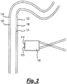
- Figure 2 shows schematically an apparatus 100 which is not according to the invention and is present for illustration purposes only, It is used to perform an assessment method on a multiple layer fluid conduit, in this case a flexible riser 120.
- the apparatus 100 is configured to be operated external to the riser (i.e. in a subsea location).
- the apparatus comprises a body on which are located a pair of wideband acoustic transducers 114, 115.
- the apparatus is deployed by an ROV (not shown).
- a transmitting transducer 114 transmits a wideband acoustic signal, which may comprise one or more chirps.
- the signal is coupled to the flexible riser by the water column to excite the pipeline.
- a second transducer 115 receives a return signal from the excited flexible riser, and a return data set is collected and stored in internal memory in the apparatus or transmitted to a remote location.
- the return signal is affected by the acoustic properties experienced between transmission and detection, including acoustic properties of the flexible riser and the volume 118 between the outer layer 122 of the riser and an internal layer 124. Analysing the return data set enables the presence of fluid to be detected by the apparatus.
- the apparatus may therefore be used to identify damage to the flexible riser, indicated by the presence of a flooded annulus. In this case, the flexible riser has a flooded annulus 118 due to water ingress through damaged portions of the flexible riser, with the level of flooding up to the water level 124.
- the apparatus 100 may also be used for the detection of defects, damage, holes, cracks, wall thickness and corrosion of the flexible riser. Comparison of the received signal with acoustic signatures collected from pipelines with defects, damage, holes, cracks, wall thickness and corrosion enables a detected feature to be characterised.
- a first transducer transmits the wideband acoustic signal
- a second transducer receives the return signal.
- a wideband acoustic signal may be transmitted and received by the same transducer, or that a number of such dual-purpose transducers may be employed.
- the transducers may be composite transducers, may have low Q-factors, e.g. less than 5 (or less than 2, or less than 1.5), and/or may have a high sensitivity, e.g. greater than 50% (or greater than 65%).
- a combination of composite and non-composite transducers, transducers of varying Q-factors, and transducers of varying sensitivities may be employed.
- Beam forming techniques can be used in the transmission and/or reception of acoustic signals, and directional (e.g. beam widths of less than 10 degrees) index beams may be employed.
- Figure 3 is a graphical diagram 300 showing an example of the design of a bio-inspired wideband acoustic signal, as may be used in preferred embodiments of the invention.
- the graph 300 plots frequency against time.
- the signal comprises a pair of overlapping down chirps 302, 304, which overlap in time to generate the acoustic excitation pulse.
- Figures 4A to 6B are examples of plots of bio-inspired wideband acoustic pulses, as may be used in preferred embodiments of the invention.
- the first plot in each drawing shows the pulse in the time domain
- the second plot shows the pulse in the frequency domain.
- plots 400a, 400b show a wideband acoustic signal 402a, 402b with a frequency range of approximately 15 kHz to about 150kHz, and a distribution of frequencies across that range.
- plots 500a, 500b show a wideband acoustic signal 502a, 502b with a frequency range of approximately 12 kHz to about 150kHz, and a distribution of frequencies across that range.
- plots 600a, 600b show a wideband acoustic signal 602a, 602b with a frequency range of approximately 10 kHz to about 150kHz, and a distribution of frequencies across that range.
- the invention provides a method of assessing a condition of a fluid conduit.
- the method comprises providing a measurement apparatus comprising at least one wideband acoustic transducer internally of a fluid conduit, and transmitting a wideband acoustic signal comprising a plurality of stacked frequency chirps from the measurement apparatus to excite at least a portion of the fluid conduit.
- the wideband acoustic signal comprises a first chirp having a first frequency range, and a second chirp having a second frequency range, higher than the first frequency range.
- the first and second chirps overlap in time for greater than 50% of the duration of the first chirp.
- the method comprises receiving a wideband acoustic signal in the measurement apparatus to obtain a wideband acoustic data set.
- the method comprises analysing the wideband acoustic data set by comparing the wideband acoustic data set with a database of wideband acoustic data signatures to assess the condition of the fluid conduit.
- the wideband acoustic signal comprises frequencies in the range of approximately 10 kHz to approximately 150 kHz.
- Applications include detecting or assessing a layer or deposit on an interior of the fluid conduit and assessing a physical condition of the fluid conduit. Water ingress into an annulus of a multiple layer conduit (such as a flexible riser) may be detected.
Landscapes
- Physics & Mathematics (AREA)
- General Health & Medical Sciences (AREA)
- Life Sciences & Earth Sciences (AREA)
- Chemical & Material Sciences (AREA)
- Analytical Chemistry (AREA)
- Biochemistry (AREA)
- Health & Medical Sciences (AREA)
- General Physics & Mathematics (AREA)
- Immunology (AREA)
- Pathology (AREA)
- Engineering & Computer Science (AREA)
- Signal Processing (AREA)
- Acoustics & Sound (AREA)
- Investigating Or Analyzing Materials By The Use Of Ultrasonic Waves (AREA)
Claims (14)
- Ein Verfahren zur Bewertung eines Zustands einer Fluidleitung (20), wobei das Verfahren Folgendes umfasst:Bereitstellung einer Messvorrichtung (10), die mindestens einen akustischen Breitbandwandler (14) innerhalb der Fluidleitung (20) umfasst;Übertragung eines akustischen Breitbandsignals, das eine Vielzahl gestapelter Frequenz-Chirps umfasst, von der Messvorrichtung (10), um zumindest einen Teil der Fluidleitung (20) anzuregen; wobei das akustische Breitbandsignal einen ersten Chirp mit einem ersten Frequenzbereich und einen zweiten Chirp mit einem zweiten Frequenzbereich, der höher als der erste Frequenzbereich ist, umfasst,und wobei sich der erste und der zweite Chirp zeitlich für mehr als 50 % der Dauer des ersten Chirps überlappen;Empfang eines akustischen Breitbandsignals in der Messvorrichtung (10), um einen Breitband-Akustikdatensatz zu erhalten, undAnalyse des Breitband-Akustikdatensatzes durch Vergleich des Breitband-Akustikdatensatzes mit einer Datenbank von Breitband-Akustikdatensignaturen, um den Zustand der Fluidleitung (20) zu beurteilen;wobei das akustische Breitbandsignal Frequenzen im Bereich von 10 kHz bis 150 kHz umfasst.
- Das Verfahren nach Anspruch 1, wobei das akustische Breitbandsignal eine untere Frequenz von 10 kHz und eine obere Frequenz von 150 kHz und eine Frequenzverteilung zwischen der oberen und der unteren Frequenz umfasst.
- Das Verfahren nach Anspruch 1 oder Anspruch 2, das die Erkennung oder Bewertung einer Schicht oder Ablagerung (18) auf einem Inneren der Fluidleitung umfasst.
- Das Verfahren nach einem der vorhergehenden Ansprüche, wobei die Messvorrichtung (10) einen Molch umfasst.
- Das Verfahren nach einem der vorhergehenden Ansprüche, wobei die Fluidleitung eine unterirdische Rohrleitung ist.
- Das Verfahren nach einem der vorhergehenden Ansprüche, wobei das Verfahren die Übertragung eines akustischen Breitbandsignals von der Messvorrichtung (10) durch ein Fluid umfasst, das die Messvorrichtung mit mindestens einem Abschnitt der Fluidleitung (20) koppelt, wobei mindestens ein akustischer Breitbandwandler (14) keinen direkten physischen Kontakt mit der Fluidleitung hat.
- Das Verfahren nach einem der vorhergehenden Ansprüche, das die Analyse des Breitband-Akustikdatensatzes durch die Analyse des Frequenzinhalts des Breitband-Akustikdatensatzes und den Vergleich des Datensatzes mit einer Datenbank von Breitband-Akustikdatensignaturen umfasst.
- Ein Messsystem (10) zur Bewertung eines Zustands einer Fluidleitung (20), wobei das System Folgendes umfasst:einen Körper (12) und mindestens einen akustischen Breitbandwandler (14), der auf dem Körper angeordnet ist;wobei der mindestens eine akustische Breitbandwandler so konfiguriert ist, dass er:ein akustisches Breitbandsignal, das eine Vielzahl gestapelter Frequenz-Chirps umfasst, in ein Fluidvolumen überträgt, das mit dem mindestens einen Abschnitt der Fluidleitung gekoppelt ist, um mindestens einen Abschnitt der Fluidleitung anzuregen; wobei das akustische Breitbandsignal einen ersten Chirp mit einem ersten Frequenzbereich und einen zweiten Chirp mit einem zweiten Frequenzbereich, der höher als der erste Frequenzbereich ist, umfasst;und wobei sich der erste und der zweite Chirp zeitlich für mehr als 50 % der Dauer des ersten Chirps überlappen;wobei der mindestens eine akustische Breitbandwandler so konfiguriert ist, dass er ein akustisches Breitbandsignal empfängt, um einen Breitband-Akustikdatensatz zu erhalten;das System einen Computer umfasst, der so konfiguriert ist, dass er den Breitband-Akustikdatensatz mit einer Datenbank von Breitband-Akustikdatensignaturen vergleicht;wobei der Körper so konfiguriert ist, dass er innerhalb der Fluidleitung angeordnet ist,und der mindestens eine akustische Breitbandwandler so konfiguriert ist, dass er ein akustisches Breitbandsignal überträgt, das Frequenzen im Bereich von 10 kHz bis 150 kHz umfasst.
- Das System (10) nach Anspruch 8, wobei das akustische Breitbandsignal eine untere Frequenz von 10 kHz und eine obere Frequenz von 150 kHz und eine Frequenzverteilung zwischen der oberen und der unteren Frequenz umfasst.
- Das System (10) nach Anspruch 8 oder Anspruch 9, wobei die Vorrichtung (10) einen Molch umfasst.
- Das System (10) nach einem der Ansprüche 8 bis 10, das so konfiguriert ist, dass es ein akustisches Breitbandsignal von der Messvorrichtung durch ein Fluid überträgt, das die Messvorrichtung mit mindestens einem Abschnitt der Fluidleitung (20) koppelt, wobei die Vorrichtung Arme (16) umfasst, die so konfiguriert sind, dass sie Kontakt zur Fluidleitung haben, so dass der mindestens eine akustische Breitbandwandler keinen direkten physischen Kontakt mit der Fluidleitung hat.
- Das System (10) nach einem der Ansprüche 8 bis 11, das eine Vielzahl von Paaren von sendenden/empfangenden akustischen Breitbandwandlern (14) umfasst.
- Das System (10) nach einem der Ansprüche 8 bis 12, wobei der akustische Breitbandwandler (14) einen Q-Faktor von weniger als 2,0 hat.
- Das System (10) nach einem der Ansprüche 8 bis 13, wobei der akustische Breitbandwandler (14) so ausgewählt ist, dass er eine im Wesentlichen lineare oder lineare akustische Reaktion bereitstellt.
Applications Claiming Priority (2)
| Application Number | Priority Date | Filing Date | Title |
|---|---|---|---|
| GBGB1211515.0A GB201211515D0 (en) | 2012-06-28 | 2012-06-28 | Methods and apparatus for acoustic assessment of fluid conduits |
| PCT/US2013/048785 WO2014005126A1 (en) | 2012-06-28 | 2013-06-28 | Method and apparatus for acoustic assessment of fluid conduits |
Publications (2)
| Publication Number | Publication Date |
|---|---|
| EP2867664A1 EP2867664A1 (de) | 2015-05-06 |
| EP2867664B1 true EP2867664B1 (de) | 2021-10-20 |
Family
ID=46704384
Family Applications (1)
| Application Number | Title | Priority Date | Filing Date |
|---|---|---|---|
| EP13744858.5A Active EP2867664B1 (de) | 2012-06-28 | 2013-06-28 | Verfahren und vorrichtung zur akustischen bewertung von fluidrohrleitungen |
Country Status (5)
| Country | Link |
|---|---|
| US (2) | US20150204820A1 (de) |
| EP (1) | EP2867664B1 (de) |
| AU (1) | AU2013282314A1 (de) |
| GB (1) | GB201211515D0 (de) |
| WO (1) | WO2014005126A1 (de) |
Families Citing this family (4)
| Publication number | Priority date | Publication date | Assignee | Title |
|---|---|---|---|---|
| CA2935783C (en) * | 2014-01-02 | 2022-07-19 | Pipelines 2 Data (P2D) Limited | Method and apparatus for acoustic assessment from the interior of fluid conduits |
| WO2017039789A1 (en) * | 2015-08-31 | 2017-03-09 | Exxonmobil Upstream Research Company Corp-Urc-E2. 4A.296 | Smart electrochemical sensor for pipeline corrosion measurement |
| US10769684B1 (en) | 2017-10-03 | 2020-09-08 | Wells Fargo Bank, N.A. | Property assessment system with buoyancy adjust device |
| DK3710804T3 (da) | 2017-11-15 | 2022-08-29 | Eni Spa | System og fremgangsmåde til fjernovervågning af integriteten af trykbærende rør ved hjælp af vibroakustiske kilder |
Citations (3)
| Publication number | Priority date | Publication date | Assignee | Title |
|---|---|---|---|---|
| US4539847A (en) * | 1984-01-03 | 1985-09-10 | Texaco Inc. | Acoustic method and apparatus for measuring thickness of a coating layer on a substrate |
| US6076407A (en) * | 1998-05-15 | 2000-06-20 | Framatome Technologies, Inc. | Pipe inspection probe |
| US20090078049A1 (en) * | 2007-09-25 | 2009-03-26 | The Regents Of The University Of California | Non-contact feature detection using ultrasonic lamb waves |
Family Cites Families (5)
| Publication number | Priority date | Publication date | Assignee | Title |
|---|---|---|---|---|
| US7656747B2 (en) * | 2005-07-22 | 2010-02-02 | Halliburton Energy Services, Inc. | Ultrasonic imaging in wells or tubulars |
| US7246522B1 (en) * | 2006-02-24 | 2007-07-24 | Battelle Memorial Institute | Methods and apparatus for multi-parameter acoustic signature inspection |
| NO327568B1 (no) | 2006-04-26 | 2009-08-17 | Det Norske Veritas As | Akustisk fremgangsmate og anordning for deteksjon eller karakterisering av et medium inneholdt i en struktur, saerlig en gass, et kondensat eller et hydrat i en rorledning for transport av hydrokarboner |
| US7748623B2 (en) * | 2006-11-08 | 2010-07-06 | Battelle Memorial Institute | Container screener |
| EP2406624A4 (de) * | 2009-03-13 | 2017-12-06 | Eugene B. Silverman | Drahtloser sensor, datenverwaltungssystem sowie verfahren zur überwachung der integrität mechanischer strukturen |
-
2012
- 2012-06-28 GB GBGB1211515.0A patent/GB201211515D0/en not_active Ceased
-
2013
- 2013-06-28 EP EP13744858.5A patent/EP2867664B1/de active Active
- 2013-06-28 US US14/411,472 patent/US20150204820A1/en not_active Abandoned
- 2013-06-28 WO PCT/US2013/048785 patent/WO2014005126A1/en not_active Ceased
- 2013-06-28 AU AU2013282314A patent/AU2013282314A1/en not_active Abandoned
-
2016
- 2016-03-22 US US15/077,766 patent/US20160202217A1/en not_active Abandoned
Patent Citations (3)
| Publication number | Priority date | Publication date | Assignee | Title |
|---|---|---|---|---|
| US4539847A (en) * | 1984-01-03 | 1985-09-10 | Texaco Inc. | Acoustic method and apparatus for measuring thickness of a coating layer on a substrate |
| US6076407A (en) * | 1998-05-15 | 2000-06-20 | Framatome Technologies, Inc. | Pipe inspection probe |
| US20090078049A1 (en) * | 2007-09-25 | 2009-03-26 | The Regents Of The University Of California | Non-contact feature detection using ultrasonic lamb waves |
Also Published As
| Publication number | Publication date |
|---|---|
| AU2013282314A1 (en) | 2015-01-29 |
| WO2014005126A1 (en) | 2014-01-03 |
| US20160202217A1 (en) | 2016-07-14 |
| GB201211515D0 (en) | 2012-08-08 |
| US20150204820A1 (en) | 2015-07-23 |
| EP2867664A1 (de) | 2015-05-06 |
Similar Documents
| Publication | Publication Date | Title |
|---|---|---|
| US7095676B2 (en) | Assessing a solids deposit in an oilfield pipe | |
| US10996203B2 (en) | Detection, monitoring, and determination of location of changes in metallic structures using multimode acoustic signals | |
| US11085899B2 (en) | Methods and apparatus for acoustic assessment from the interior of fluid conduits | |
| US10585069B2 (en) | Detection, monitoring, and determination of location of changes in metallic structures using multimode acoustic signals | |
| US20150338378A1 (en) | Ultrasonic signal time-frequency decomposition for borehole evaluation or pipeline inspection | |
| US10156653B2 (en) | Techniques for removing interface noise from acoustic log data | |
| CA2699474C (en) | Acoustic thickness measurements using gas as a coupling medium | |
| EP3151037A1 (de) | Systeme und verfahren zur auswertung von ringförmigem material mittels strahlformung aus akustischen arrays | |
| EP3785027B1 (de) | Detektion, überwachung und positionsbestimmung von änderungen in metallischen strukturen mittels multimodaler akustischer signale | |
| EP3151038A1 (de) | Systeme, verfahren und computerlesbare medien zur bestimmung der scherwelle-zu-druckwelle-geschwindigkeitsverhältnisse in bohrlochverrohrungen | |
| CA2650551C (en) | Acoustic method and apparatus for detection and characterization of a medium | |
| US20160202217A1 (en) | Methods and apparatus for acoustic assessment of fluid conduits | |
| US11585789B2 (en) | Method for detecting faults in plates | |
| Bertoncini et al. | 3D characterization of defects in Guided Wave monitoring of pipework using a magnetostrictive sensor | |
| Dhutti et al. | Using Ultrasonic Guided Waves | |
| CN121253683A (zh) | 基于低频机械波响应的海底管道典型大尺度缺陷远距离检测方法 |
Legal Events
| Date | Code | Title | Description |
|---|---|---|---|
| PUAI | Public reference made under article 153(3) epc to a published international application that has entered the european phase |
Free format text: ORIGINAL CODE: 0009012 |
|
| 17P | Request for examination filed |
Effective date: 20141223 |
|
| AK | Designated contracting states |
Kind code of ref document: A1 Designated state(s): AL AT BE BG CH CY CZ DE DK EE ES FI FR GB GR HR HU IE IS IT LI LT LU LV MC MK MT NL NO PL PT RO RS SE SI SK SM TR |
|
| AX | Request for extension of the european patent |
Extension state: BA ME |
|
| DAX | Request for extension of the european patent (deleted) | ||
| STAA | Information on the status of an ep patent application or granted ep patent |
Free format text: STATUS: EXAMINATION IS IN PROGRESS |
|
| 17Q | First examination report despatched |
Effective date: 20180927 |
|
| REG | Reference to a national code |
Ref country code: DE Ref legal event code: R079 Ref document number: 602013079721 Country of ref document: DE Free format text: PREVIOUS MAIN CLASS: G01N0029340000 Ipc: G01N0029040000 |
|
| GRAP | Despatch of communication of intention to grant a patent |
Free format text: ORIGINAL CODE: EPIDOSNIGR1 |
|
| STAA | Information on the status of an ep patent application or granted ep patent |
Free format text: STATUS: GRANT OF PATENT IS INTENDED |
|
| RIC1 | Information provided on ipc code assigned before grant |
Ipc: G01N 29/04 20060101AFI20201116BHEP Ipc: G01N 29/42 20060101ALI20201116BHEP Ipc: G01N 29/34 20060101ALI20201116BHEP |
|
| INTG | Intention to grant announced |
Effective date: 20201211 |
|
| GRAJ | Information related to disapproval of communication of intention to grant by the applicant or resumption of examination proceedings by the epo deleted |
Free format text: ORIGINAL CODE: EPIDOSDIGR1 |
|
| STAA | Information on the status of an ep patent application or granted ep patent |
Free format text: STATUS: EXAMINATION IS IN PROGRESS |
|
| INTC | Intention to grant announced (deleted) | ||
| GRAP | Despatch of communication of intention to grant a patent |
Free format text: ORIGINAL CODE: EPIDOSNIGR1 |
|
| STAA | Information on the status of an ep patent application or granted ep patent |
Free format text: STATUS: GRANT OF PATENT IS INTENDED |
|
| INTG | Intention to grant announced |
Effective date: 20210517 |
|
| GRAS | Grant fee paid |
Free format text: ORIGINAL CODE: EPIDOSNIGR3 |
|
| GRAA | (expected) grant |
Free format text: ORIGINAL CODE: 0009210 |
|
| STAA | Information on the status of an ep patent application or granted ep patent |
Free format text: STATUS: THE PATENT HAS BEEN GRANTED |
|
| AK | Designated contracting states |
Kind code of ref document: B1 Designated state(s): AL AT BE BG CH CY CZ DE DK EE ES FI FR GB GR HR HU IE IS IT LI LT LU LV MC MK MT NL NO PL PT RO RS SE SI SK SM TR |
|
| REG | Reference to a national code |
Ref country code: GB Ref legal event code: FG4D |
|
| REG | Reference to a national code |
Ref country code: CH Ref legal event code: EP |
|
| REG | Reference to a national code |
Ref country code: IE Ref legal event code: FG4D |
|
| REG | Reference to a national code |
Ref country code: DE Ref legal event code: R096 Ref document number: 602013079721 Country of ref document: DE |
|
| REG | Reference to a national code |
Ref country code: AT Ref legal event code: REF Ref document number: 1440350 Country of ref document: AT Kind code of ref document: T Effective date: 20211115 |
|
| REG | Reference to a national code |
Ref country code: NL Ref legal event code: FP |
|
| REG | Reference to a national code |
Ref country code: LT Ref legal event code: MG9D |
|
| REG | Reference to a national code |
Ref country code: NO Ref legal event code: T2 Effective date: 20211020 |
|
| REG | Reference to a national code |
Ref country code: AT Ref legal event code: MK05 Ref document number: 1440350 Country of ref document: AT Kind code of ref document: T Effective date: 20211020 |
|
| PG25 | Lapsed in a contracting state [announced via postgrant information from national office to epo] |
Ref country code: RS Free format text: LAPSE BECAUSE OF FAILURE TO SUBMIT A TRANSLATION OF THE DESCRIPTION OR TO PAY THE FEE WITHIN THE PRESCRIBED TIME-LIMIT Effective date: 20211020 Ref country code: LT Free format text: LAPSE BECAUSE OF FAILURE TO SUBMIT A TRANSLATION OF THE DESCRIPTION OR TO PAY THE FEE WITHIN THE PRESCRIBED TIME-LIMIT Effective date: 20211020 Ref country code: FI Free format text: LAPSE BECAUSE OF FAILURE TO SUBMIT A TRANSLATION OF THE DESCRIPTION OR TO PAY THE FEE WITHIN THE PRESCRIBED TIME-LIMIT Effective date: 20211020 Ref country code: BG Free format text: LAPSE BECAUSE OF FAILURE TO SUBMIT A TRANSLATION OF THE DESCRIPTION OR TO PAY THE FEE WITHIN THE PRESCRIBED TIME-LIMIT Effective date: 20220120 Ref country code: AT Free format text: LAPSE BECAUSE OF FAILURE TO SUBMIT A TRANSLATION OF THE DESCRIPTION OR TO PAY THE FEE WITHIN THE PRESCRIBED TIME-LIMIT Effective date: 20211020 |
|
| PG25 | Lapsed in a contracting state [announced via postgrant information from national office to epo] |
Ref country code: IS Free format text: LAPSE BECAUSE OF FAILURE TO SUBMIT A TRANSLATION OF THE DESCRIPTION OR TO PAY THE FEE WITHIN THE PRESCRIBED TIME-LIMIT Effective date: 20220220 Ref country code: SE Free format text: LAPSE BECAUSE OF FAILURE TO SUBMIT A TRANSLATION OF THE DESCRIPTION OR TO PAY THE FEE WITHIN THE PRESCRIBED TIME-LIMIT Effective date: 20211020 Ref country code: PT Free format text: LAPSE BECAUSE OF FAILURE TO SUBMIT A TRANSLATION OF THE DESCRIPTION OR TO PAY THE FEE WITHIN THE PRESCRIBED TIME-LIMIT Effective date: 20220221 Ref country code: PL Free format text: LAPSE BECAUSE OF FAILURE TO SUBMIT A TRANSLATION OF THE DESCRIPTION OR TO PAY THE FEE WITHIN THE PRESCRIBED TIME-LIMIT Effective date: 20211020 Ref country code: LV Free format text: LAPSE BECAUSE OF FAILURE TO SUBMIT A TRANSLATION OF THE DESCRIPTION OR TO PAY THE FEE WITHIN THE PRESCRIBED TIME-LIMIT Effective date: 20211020 Ref country code: HR Free format text: LAPSE BECAUSE OF FAILURE TO SUBMIT A TRANSLATION OF THE DESCRIPTION OR TO PAY THE FEE WITHIN THE PRESCRIBED TIME-LIMIT Effective date: 20211020 Ref country code: GR Free format text: LAPSE BECAUSE OF FAILURE TO SUBMIT A TRANSLATION OF THE DESCRIPTION OR TO PAY THE FEE WITHIN THE PRESCRIBED TIME-LIMIT Effective date: 20220121 Ref country code: ES Free format text: LAPSE BECAUSE OF FAILURE TO SUBMIT A TRANSLATION OF THE DESCRIPTION OR TO PAY THE FEE WITHIN THE PRESCRIBED TIME-LIMIT Effective date: 20211020 |
|
| REG | Reference to a national code |
Ref country code: DE Ref legal event code: R097 Ref document number: 602013079721 Country of ref document: DE |
|
| PG25 | Lapsed in a contracting state [announced via postgrant information from national office to epo] |
Ref country code: SM Free format text: LAPSE BECAUSE OF FAILURE TO SUBMIT A TRANSLATION OF THE DESCRIPTION OR TO PAY THE FEE WITHIN THE PRESCRIBED TIME-LIMIT Effective date: 20211020 Ref country code: SK Free format text: LAPSE BECAUSE OF FAILURE TO SUBMIT A TRANSLATION OF THE DESCRIPTION OR TO PAY THE FEE WITHIN THE PRESCRIBED TIME-LIMIT Effective date: 20211020 Ref country code: RO Free format text: LAPSE BECAUSE OF FAILURE TO SUBMIT A TRANSLATION OF THE DESCRIPTION OR TO PAY THE FEE WITHIN THE PRESCRIBED TIME-LIMIT Effective date: 20211020 Ref country code: EE Free format text: LAPSE BECAUSE OF FAILURE TO SUBMIT A TRANSLATION OF THE DESCRIPTION OR TO PAY THE FEE WITHIN THE PRESCRIBED TIME-LIMIT Effective date: 20211020 Ref country code: DK Free format text: LAPSE BECAUSE OF FAILURE TO SUBMIT A TRANSLATION OF THE DESCRIPTION OR TO PAY THE FEE WITHIN THE PRESCRIBED TIME-LIMIT Effective date: 20211020 Ref country code: CZ Free format text: LAPSE BECAUSE OF FAILURE TO SUBMIT A TRANSLATION OF THE DESCRIPTION OR TO PAY THE FEE WITHIN THE PRESCRIBED TIME-LIMIT Effective date: 20211020 |
|
| PLBE | No opposition filed within time limit |
Free format text: ORIGINAL CODE: 0009261 |
|
| STAA | Information on the status of an ep patent application or granted ep patent |
Free format text: STATUS: NO OPPOSITION FILED WITHIN TIME LIMIT |
|
| 26N | No opposition filed |
Effective date: 20220721 |
|
| PG25 | Lapsed in a contracting state [announced via postgrant information from national office to epo] |
Ref country code: AL Free format text: LAPSE BECAUSE OF FAILURE TO SUBMIT A TRANSLATION OF THE DESCRIPTION OR TO PAY THE FEE WITHIN THE PRESCRIBED TIME-LIMIT Effective date: 20211020 |
|
| PG25 | Lapsed in a contracting state [announced via postgrant information from national office to epo] |
Ref country code: SI Free format text: LAPSE BECAUSE OF FAILURE TO SUBMIT A TRANSLATION OF THE DESCRIPTION OR TO PAY THE FEE WITHIN THE PRESCRIBED TIME-LIMIT Effective date: 20211020 |
|
| PG25 | Lapsed in a contracting state [announced via postgrant information from national office to epo] |
Ref country code: MC Free format text: LAPSE BECAUSE OF FAILURE TO SUBMIT A TRANSLATION OF THE DESCRIPTION OR TO PAY THE FEE WITHIN THE PRESCRIBED TIME-LIMIT Effective date: 20211020 |
|
| REG | Reference to a national code |
Ref country code: CH Ref legal event code: PL |
|
| REG | Reference to a national code |
Ref country code: BE Ref legal event code: MM Effective date: 20220630 |
|
| PG25 | Lapsed in a contracting state [announced via postgrant information from national office to epo] |
Ref country code: LU Free format text: LAPSE BECAUSE OF NON-PAYMENT OF DUE FEES Effective date: 20220628 Ref country code: LI Free format text: LAPSE BECAUSE OF NON-PAYMENT OF DUE FEES Effective date: 20220630 Ref country code: CH Free format text: LAPSE BECAUSE OF NON-PAYMENT OF DUE FEES Effective date: 20220630 |
|
| PG25 | Lapsed in a contracting state [announced via postgrant information from national office to epo] |
Ref country code: IT Free format text: LAPSE BECAUSE OF FAILURE TO SUBMIT A TRANSLATION OF THE DESCRIPTION OR TO PAY THE FEE WITHIN THE PRESCRIBED TIME-LIMIT Effective date: 20211020 Ref country code: BE Free format text: LAPSE BECAUSE OF NON-PAYMENT OF DUE FEES Effective date: 20220630 |
|
| P01 | Opt-out of the competence of the unified patent court (upc) registered |
Effective date: 20230529 |
|
| PG25 | Lapsed in a contracting state [announced via postgrant information from national office to epo] |
Ref country code: HU Free format text: LAPSE BECAUSE OF FAILURE TO SUBMIT A TRANSLATION OF THE DESCRIPTION OR TO PAY THE FEE WITHIN THE PRESCRIBED TIME-LIMIT; INVALID AB INITIO Effective date: 20130628 |
|
| PG25 | Lapsed in a contracting state [announced via postgrant information from national office to epo] |
Ref country code: MK Free format text: LAPSE BECAUSE OF FAILURE TO SUBMIT A TRANSLATION OF THE DESCRIPTION OR TO PAY THE FEE WITHIN THE PRESCRIBED TIME-LIMIT Effective date: 20211020 Ref country code: CY Free format text: LAPSE BECAUSE OF FAILURE TO SUBMIT A TRANSLATION OF THE DESCRIPTION OR TO PAY THE FEE WITHIN THE PRESCRIBED TIME-LIMIT Effective date: 20211020 |
|
| PG25 | Lapsed in a contracting state [announced via postgrant information from national office to epo] |
Ref country code: MT Free format text: LAPSE BECAUSE OF FAILURE TO SUBMIT A TRANSLATION OF THE DESCRIPTION OR TO PAY THE FEE WITHIN THE PRESCRIBED TIME-LIMIT Effective date: 20211020 |
|
| PGFP | Annual fee paid to national office [announced via postgrant information from national office to epo] |
Ref country code: DE Payment date: 20250630 Year of fee payment: 13 |
|
| PGFP | Annual fee paid to national office [announced via postgrant information from national office to epo] |
Ref country code: GB Payment date: 20250526 Year of fee payment: 13 |
|
| PGFP | Annual fee paid to national office [announced via postgrant information from national office to epo] |
Ref country code: NO Payment date: 20250527 Year of fee payment: 13 |
|
| PGFP | Annual fee paid to national office [announced via postgrant information from national office to epo] |
Ref country code: NL Payment date: 20250626 Year of fee payment: 13 |
|
| PGFP | Annual fee paid to national office [announced via postgrant information from national office to epo] |
Ref country code: FR Payment date: 20250527 Year of fee payment: 13 |
|
| PGFP | Annual fee paid to national office [announced via postgrant information from national office to epo] |
Ref country code: IE Payment date: 20250526 Year of fee payment: 13 |
|
| PG25 | Lapsed in a contracting state [announced via postgrant information from national office to epo] |
Ref country code: TR Free format text: LAPSE BECAUSE OF FAILURE TO SUBMIT A TRANSLATION OF THE DESCRIPTION OR TO PAY THE FEE WITHIN THE PRESCRIBED TIME-LIMIT Effective date: 20211020 |