EP2867443B1 - Verfahren und systeme zum testen der integrität von komponenten eines kohlenwasserstoffbohrlochsystems - Google Patents
Verfahren und systeme zum testen der integrität von komponenten eines kohlenwasserstoffbohrlochsystems Download PDFInfo
- Publication number
- EP2867443B1 EP2867443B1 EP13727471.8A EP13727471A EP2867443B1 EP 2867443 B1 EP2867443 B1 EP 2867443B1 EP 13727471 A EP13727471 A EP 13727471A EP 2867443 B1 EP2867443 B1 EP 2867443B1
- Authority
- EP
- European Patent Office
- Prior art keywords
- pressure
- temperature
- time
- computer
- well system
- Prior art date
- Legal status (The legal status is an assumption and is not a legal conclusion. Google has not performed a legal analysis and makes no representation as to the accuracy of the status listed.)
- Not-in-force
Links
- 238000012360 testing method Methods 0.000 title claims description 167
- 238000000034 method Methods 0.000 title claims description 66
- 229930195733 hydrocarbon Natural products 0.000 title claims description 21
- 150000002430 hydrocarbons Chemical class 0.000 title claims description 21
- 239000004215 Carbon black (E152) Substances 0.000 title claims description 19
- 230000008859 change Effects 0.000 claims description 36
- 239000012530 fluid Substances 0.000 claims description 28
- 238000007789 sealing Methods 0.000 claims description 8
- 238000004891 communication Methods 0.000 claims description 7
- 238000004458 analytical method Methods 0.000 claims description 6
- 230000001010 compromised effect Effects 0.000 claims 4
- 238000012417 linear regression Methods 0.000 claims 2
- 238000009844 basic oxygen steelmaking Methods 0.000 description 68
- 230000008569 process Effects 0.000 description 41
- 238000010586 diagram Methods 0.000 description 12
- 238000011016 integrity testing Methods 0.000 description 12
- 238000003860 storage Methods 0.000 description 11
- 238000005553 drilling Methods 0.000 description 6
- 230000006399 behavior Effects 0.000 description 5
- 230000015572 biosynthetic process Effects 0.000 description 4
- 230000000694 effects Effects 0.000 description 4
- 239000013535 sea water Substances 0.000 description 3
- XLYOFNOQVPJJNP-UHFFFAOYSA-N water Substances O XLYOFNOQVPJJNP-UHFFFAOYSA-N 0.000 description 3
- 230000003466 anti-cipated effect Effects 0.000 description 2
- 230000033228 biological regulation Effects 0.000 description 2
- 230000004941 influx Effects 0.000 description 2
- 238000002955 isolation Methods 0.000 description 2
- 238000004519 manufacturing process Methods 0.000 description 2
- 230000007246 mechanism Effects 0.000 description 2
- 238000012544 monitoring process Methods 0.000 description 2
- 230000003287 optical effect Effects 0.000 description 2
- 238000010008 shearing Methods 0.000 description 2
- 229910000760 Hardened steel Inorganic materials 0.000 description 1
- 229910000831 Steel Inorganic materials 0.000 description 1
- 238000013459 approach Methods 0.000 description 1
- 230000000740 bleeding effect Effects 0.000 description 1
- 230000008867 communication pathway Effects 0.000 description 1
- 239000004020 conductor Substances 0.000 description 1
- 238000005520 cutting process Methods 0.000 description 1
- 238000007405 data analysis Methods 0.000 description 1
- 230000007423 decrease Effects 0.000 description 1
- 238000011161 development Methods 0.000 description 1
- 238000002405 diagnostic procedure Methods 0.000 description 1
- 238000009826 distribution Methods 0.000 description 1
- 230000007613 environmental effect Effects 0.000 description 1
- 230000002706 hydrostatic effect Effects 0.000 description 1
- 238000012423 maintenance Methods 0.000 description 1
- 239000002184 metal Substances 0.000 description 1
- 238000012986 modification Methods 0.000 description 1
- 230000004048 modification Effects 0.000 description 1
- 238000007619 statistical method Methods 0.000 description 1
- 239000010959 steel Substances 0.000 description 1
- 230000000007 visual effect Effects 0.000 description 1
Images


Classifications
-
- E—FIXED CONSTRUCTIONS
- E21—EARTH OR ROCK DRILLING; MINING
- E21B—EARTH OR ROCK DRILLING; OBTAINING OIL, GAS, WATER, SOLUBLE OR MELTABLE MATERIALS OR A SLURRY OF MINERALS FROM WELLS
- E21B47/00—Survey of boreholes or wells
- E21B47/06—Measuring temperature or pressure
-
- E—FIXED CONSTRUCTIONS
- E21—EARTH OR ROCK DRILLING; MINING
- E21B—EARTH OR ROCK DRILLING; OBTAINING OIL, GAS, WATER, SOLUBLE OR MELTABLE MATERIALS OR A SLURRY OF MINERALS FROM WELLS
- E21B33/00—Sealing or packing boreholes or wells
- E21B33/02—Surface sealing or packing
- E21B33/03—Well heads; Setting-up thereof
- E21B33/06—Blow-out preventers, i.e. apparatus closing around a drill pipe, e.g. annular blow-out preventers
- E21B33/064—Blow-out preventers, i.e. apparatus closing around a drill pipe, e.g. annular blow-out preventers specially adapted for underwater well heads
-
- E—FIXED CONSTRUCTIONS
- E21—EARTH OR ROCK DRILLING; MINING
- E21B—EARTH OR ROCK DRILLING; OBTAINING OIL, GAS, WATER, SOLUBLE OR MELTABLE MATERIALS OR A SLURRY OF MINERALS FROM WELLS
- E21B47/00—Survey of boreholes or wells
- E21B47/001—Survey of boreholes or wells for underwater installation
-
- E—FIXED CONSTRUCTIONS
- E21—EARTH OR ROCK DRILLING; MINING
- E21B—EARTH OR ROCK DRILLING; OBTAINING OIL, GAS, WATER, SOLUBLE OR MELTABLE MATERIALS OR A SLURRY OF MINERALS FROM WELLS
- E21B33/00—Sealing or packing boreholes or wells
- E21B33/02—Surface sealing or packing
- E21B33/03—Well heads; Setting-up thereof
- E21B33/035—Well heads; Setting-up thereof specially adapted for underwater installations
- E21B33/0355—Control systems, e.g. hydraulic, pneumatic, electric, acoustic, for submerged well heads
Definitions
- Implementations of the present teachings relate to systems and methods for testing the pressure integrity of different components of a well system.
- a component of a well system can be tested by isolating the component of the well system, such as the wellhead or portions of the blowout preventer stack. Once isolated, the component of the well system can be pressurized to a test pressure via one or more supply lines connected to the component of the well system, e.g. a choke line and a kill line.
- the process can begin.
- a user can desire to test the pressure integrity of a portion 402 of the BOP stack 110, e.g. the pipe ram 404.
- a user operating the testing tool 124 on the computer 122 can initiate the pressure integrity testing on the portion 402 of the BOP stack 110.
- the computer 122, executing the testing tool 124 can be configured to automatically initiate the pressure integrity testing on the portion 402 of the BOP stack 110, whether at a defined time or periodically.
- the computer 122 can isolate the component of the well system 100 under test.
- the computer 122 executing the testing tool 124, can communicate with the BOP controls 224 to close a pipe ram 404 and an inverted test ram 406 in the BOP stack 110 and a kill valves 408.
- the portion 402 of the BOP stack 110 can be isolated from the remainder of the BOP stack 110.
- the computer 122 can pressurize one or more of the supply lines and the component of the well system 100.
- the computer 122 executing the testing tool 124, can communicate with the high pressure pump 112 to pressurize the choke line 114 and the portion 402 of the BOP stack 110 to a test pressure.
- the choke line 114, the portion 402 can be pressurized to a pressure adequate to test the portion 402 while maintaining safe operating pressures in the well system 100.
- the process can end, return to any point or repeat.
- the above process can be made applicable to cases of pressurization via drill string, but only if a majority of the drill string fluid volume can be isolated from the downhole pressure-tested cavity once the cavity is pressurized.
- Certain BOP test tools might be modified through addition of a sealing mechanism that permits pressurization from surface when opened yet blocks the pressure path to surface when closed.
- a suitable check-valve arrangement might provide such a sealing mechanism.
- the computer 122 can provide the data gathered during pressure integrity testing to other computer systems connected to the computer 122 via the network 218. Additionally, the computer 122 can display the data gathered during the integrity testing in a graphical form on a display associated with the computer 122.
- an example BOP stack 1000 configuration is shown comprising several individual blowout preventers assemble together.
- the primary well control is achieved by hydrostatic pressure: the weight of the drilling mud counterbalances pressure from the reservoir and prevents hydrocarbons from flowing into the wellbore.
- the BOP stack 1000 serves as a secondary means of well control, such that when a formation influx occurs during drilling, one or more BOPs 1015, 1025, 1030, 1035, 1040, 1045, 1050, 1055, and 1060 are activated to seal the annulus or wellbore.
- Denser or heavier mud is then pumped through the choke line 1002, having valves 1007, kill line 1003, having valves 1005, and/or mud boost line 1004, having valve 1009, until the downhole pressure is controlled and the influx is circulated out of the well. Once this "kill weight” mud extends from the bottom of the well to the top, the well is back in balance and has been “killed.”
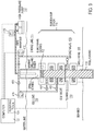
- an example BOP stack 1100 configuration is shown including a flex joint 1110, a upper annular 1115, a riser connector 1120 for the lower marine riser package (LMRP), a lower annular 1125, blind/shear rams 1030, an upper pipe ram 1135, an upper middle pipe ram 1140, a lower middle pipe ram 1145, a lower pipe ram 1150, a wellhead connector 1055, and a test cap/plug 1060.
- Pressure/temperature sensors 1165 can be arranged relative to the choke line 1102, the kill line 1103, and, for example, between the lower middle pipe ram 1145 and the lower pipe ram 1150.
- pressure can be released at end of a test by opening a CU valve and bleeding back fluid to surface.
- This can be included with process 300 and can include opening a subsea choke or kill valve in advance of opening a CU valve. It is expected that at end of subsea BOP or casing/liner tests conducted per process 300 there will be a pressure differential across the subsea valve potentially of over 1380 kPa (several hundred psi). The pressure difference will be the amount of pressure decline that occurs in the choke or kill line minus that which occurs in the test cavity during the shut-in test period. Both will be measured during the test period so the pressure difference can be reliably estimated.
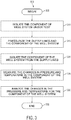
- FIG. 12 is a flow diagram that illustrates another exemplary process 1200 for testing components of the well system 100.
- the exemplary process can be performed on any component of the well system 100, for example.
- the computer 122 executing the testing tool 124, can analyze the changes in pressure and temperature for the component of the well system 100 as described above.
- the process can end, return to any point or repeat.
- a pressure and a temperature of the test fluid in the component can be measured that was pressurized over a period of time.
- one or more sensors can be controlled by the computer 122 and can be arranged at one or more locations along the wellbore, including along the tool string inside the wellbore or proximate to the casing in the wellbore.
- the one or more sensors can be operable to measure pressure, temperature, or both for a period of time.
Landscapes
- Geology (AREA)
- Life Sciences & Earth Sciences (AREA)
- Engineering & Computer Science (AREA)
- Mining & Mineral Resources (AREA)
- Physics & Mathematics (AREA)
- Environmental & Geological Engineering (AREA)
- Fluid Mechanics (AREA)
- General Life Sciences & Earth Sciences (AREA)
- Geochemistry & Mineralogy (AREA)
- Geophysics (AREA)
- Examining Or Testing Airtightness (AREA)
- Measuring Fluid Pressure (AREA)
- Testing Of Devices, Machine Parts, Or Other Structures Thereof (AREA)
Claims (15)
- Computer-implementiertes Verfahren zum Testen von Komponenten eines Kohlenwasserstoff-Bohrlochsystems (100), umfassend:Isolieren (1410) einer Komponente (402) des Kohlenwasserstoff-Bohrlochsystems (100) und einer ersten Zuleitung (114) zu der Komponente (402) von anderen Komponenten des Kohlenwasserstoff-Bohrlochsystems (100);Druckbeaufschlagen (1415) der Komponente (402) und der ersten Zuleitung (114) mit einem Testdruck mit einem Testfluid;Messen (1420), über einen Zeitraum, des Drucks und der Temperatur des Testfluids in der druckbeaufschlagten Komponente (402), umfassend:Bestimmen der Druckveränderung über den Zeitraum;Bestimmen der Temperaturveränderung über den Zeitraum undAuftragen der Druckveränderung über den Zeitraum gegen die Temperaturveränderung über den Zeitraum, umfassend das Bestimmen einer Linie der linearen optimalen Anpassung unter Verwendung eines linearen Regressionsalgorithmus;Analysieren (1425), durch einen Prozessor, des Drucks und der Temperatur, die gemessen wurden; undBestimmen (1430) der Druckintegrität der Komponente (402), basierend auf der Analyse.
- Computer-implementiertes Verfahren nach Anspruch 1, wobei das Verfahren ferner umfasst:
Testen der Druckintegrität der ersten Zuleitung (114) vor dem Druckbeaufschlagen der ersten Zuleitung (114). - Computer-implementiertes Verfahren nach Anspruch 1 oder 2, wobei:
die Komponente (402) des Kohlenwasserstoff-Bohrlochsystems (100) zumindest eines von einem Bohrlochkopf (106) und einem Abschnitt eines Blowout-Preventers (110) umfasst; und die erste Zuleitung (114) eine Totpumpleitung (116) oder eine Drosselleitung (114) umfasst. - Computer-implementiertes Verfahren nach einem der obigen Ansprüche, wobei das Isolieren der Komponente (402) und der ersten Zuleitung (114) umfasst:
Schließen eines oder mehrerer Ventile (408) in dem Kohlenwasserstoff-Bohrlochsystem (100). - Computer-implementiertes Verfahren nach einem der obigen Ansprüche, wobei das Isolieren der Komponente (402) und der ersten Zuleitung (114) umfasst:
Schließen einer oder mehrerer Abdichtungsstrukturen oberhalb (404) und unterhalb (406) der Komponente. - Computer-implementiertes Verfahren nach einem der obigen Ansprüche, wobei das Verfahren ferner umfasst:
Messen des Drucks und der Temperatur zu einem zweiten Zeitpunkt und Vergleichen des Drucks und der Temperatur, die zu dem zweiten Zeitpunkt gemessen wurden, mit der Linie der linearen optimalen Anpassung. - Computer-implementiertes Verfahren nach Anspruch 6, wobei das Vergleichen des Drucks und der Temperatur, die zu dem zweiten Zeitpunkt gemessen wurden, mit der Linie der linearen optimalen Anpassung ferner umfasst:
Bestimmen, dass die Druckintegrität der Komponente (402) beeinträchtigt worden ist, wenn der Druck und die Temperatur, die zu dem zweiten Zeitpunkt gemessen wurden, unterhalb der Linie der linearen optimalen Anpassung liegen. - Computer-implementiertes Verfahren nach Anspruch 6 oder 7, wobei das Vergleichen des Drucks und der Temperatur, die zu dem zweiten Zeitpunkt gemessen wurden, mit der Linie der linearen optimalen Anpassung ferner umfasst:
Bestimmen, dass die Druckintegrität der Komponente (402) nicht beeinträchtigt worden ist, wenn der Druck und die Temperatur, die zu dem zweiten Zeitpunkt gemessen wurden, entlang oder in der Nähe der Linie der linearen optimalen Anpassung liegen. - Computer-implementiertes Verfahren nach Anspruch 6, 7 oder 8, wobei das Vergleichen des Drucks und der Temperatur, die zu dem zweiten Zeitpunkt gemessen wurden, mit der Linie der linearen optimalen Anpassung ferner umfasst:
Bestimmen der Gegenwart einer externen nicht-repräsentativen Druckbeaufschlagungsquelle, wenn der Druck und die Temperatur, die zu dem zweiten Zeitpunkt gemessen wurden, oberhalb der Linie der linearen optimalen Anpassung liegen. - Computer-implementiertes Verfahren nach einem der obigen Ansprüche, wobei das Analysieren des Drucks und der Temperatur, die gemessen wurden, umfasst:
Vergleichen des Drucks und der Temperatur, die gemessen wurden, mit historischen Druck- und Temperaturdaten, die für das Kohlenwasserstoff-Bohrlochsystem (100) erhalten wurden. - Bohrlochsystem (100), umfassend:eine Blowout-Preventergarnitur (110), umfassend mehrere Dichtungsbauteile (404; 406), die zwischen einer geöffneten Position und einer geschlossenen Position geschaltet werden können;eine oder mehrere Zuleitungen (114; 116) in Fluidkommunikation mit der Blowout-Preventergarnitur (110);einen oder mehrere Temperatursensoren und einen oder mehrere Drucksensoren, die nahe der Blowout-Preventergarnitur (110) angeordnet sind, um die Temperatur bzw. den Druck eines Testbereiches (402) in der Blowout-Preventergarnitur (110) zu messen; undeinen Computer (122) in Kommunikation mit Komponenten der Blowout-Preventergarnitur (110), dem einen oder den mehreren Temperatursensoren und dem einen oder den mehreren Drucksensoren, wobei der Computer (112) so ausgebildet ist, dass er ein Verfahren ausführt, umfassend:Isolieren (1410) des Testbereiches (402) und einer ersten Zuleitung (114) zu dem Testbereich von anderen Komponenten der Blowout-Preventergarnitur (110);Druckbeaufschlagen (1415) des Testbereiches (402) und der ersten Zuleitung (114) mit einem Testdruck mit einem Testfluid;Messen (1420), über einen Zeitraum, des Drucks und der Temperatur des Testfluids in dem druckbeaufschlagten Testbereich (402), umfassend:Bestimmen der Druckveränderung über den Zeitraum;Bestimmen der Temperaturveränderung über den Zeitraum undAuftragen der Druckveränderung über den Zeitraum gegen die Temperaturveränderung über den Zeitraum, umfassend das Bestimmen einer Linie der linearen optimalen Anpassung unter Verwendung eines linearen Regressionsalgorithmus;Analysieren (1425) des Drucks und der Temperatur, die gemessen wurden; undBestimmen (1430) der Druckintegrität des Testbereiches (402), basierend auf der Analyse.
- Bohrlochsystem nach Anspruch 11, wobei das Verfahren ferner umfasst:Messen des Drucks und der Temperatur zu einem zweiten Zeitpunkt undVergleichen des Drucks und der Temperatur, die zu dem zweiten Zeitpunkt gemessen wurden, mit der Linie der linearen optimalen Anpassung.
- Bohrlochsystem nach Anspruch 12, wobei das Vergleichen des Drucks und der Temperatur, die zu dem zweiten Zeitpunkt gemessen wurden, mit der Linie der linearen optimalen Anpassung ferner umfasst:
Bestimmen, dass die Druckintegrität der Komponente (402) beeinträchtigt worden ist, wenn der Druck und die Temperatur, die zu dem zweiten Zeitpunkt gemessen wurden, unterhalb der Linie der linearen optimalen Anpassung liegen. - Bohrlochsystem nach Anspruch 12 oder 13, wobei das Vergleichen des Drucks und der Temperatur, die zu dem zweiten Zeitpunkt gemessen wurden, mit der Linie der linearen optimalen Anpassung ferner umfasst:
Bestimmen, dass die Druckintegrität der Komponente (402) nicht beeinträchtigt worden ist, wenn der Druck und die Temperatur, die zu dem zweiten Zeitpunkt gemessen wurden, entlang oder in der Nähe der Linie der linearen optimalen Anpassung liegen. - Bohrlochsystem nach Anspruch 12, 13 oder 14, wobei das Vergleichen des Drucks und der Temperatur, die zu dem zweiten Zeitpunkt gemessen wurden, mit der Linie der linearen optimalen Anpassung ferner umfasst:
Bestimmen der Gegenwart einer externen nicht-repräsentativen Druckbeaufschlagungsquelle, wenn der Druck und die Temperatur, die zu dem zweiten Zeitpunkt gemessen wurden, oberhalb der Linie der linearen optimalen Anpassung liegen.
Applications Claiming Priority (3)
| Application Number | Priority Date | Filing Date | Title |
|---|---|---|---|
| US201261649653P | 2012-05-21 | 2012-05-21 | |
| US201361799041P | 2013-03-15 | 2013-03-15 | |
| PCT/US2013/042019 WO2013177161A2 (en) | 2012-05-21 | 2013-05-21 | Methods and systems for testing the integrity of components of a hydrocarbon well system |
Publications (2)
| Publication Number | Publication Date |
|---|---|
| EP2867443A2 EP2867443A2 (de) | 2015-05-06 |
| EP2867443B1 true EP2867443B1 (de) | 2019-03-27 |
Family
ID=48577273
Family Applications (1)
| Application Number | Title | Priority Date | Filing Date |
|---|---|---|---|
| EP13727471.8A Not-in-force EP2867443B1 (de) | 2012-05-21 | 2013-05-21 | Verfahren und systeme zum testen der integrität von komponenten eines kohlenwasserstoffbohrlochsystems |
Country Status (5)
| Country | Link |
|---|---|
| US (1) | US9429010B2 (de) |
| EP (1) | EP2867443B1 (de) |
| AU (1) | AU2013266524B2 (de) |
| BR (1) | BR112014029097A2 (de) |
| WO (1) | WO2013177161A2 (de) |
Families Citing this family (27)
| Publication number | Priority date | Publication date | Assignee | Title |
|---|---|---|---|---|
| US10215009B2 (en) | 2013-06-30 | 2019-02-26 | Sigurd Tjostheim | System and console for monitoring data stream quality in drilling and production operations at a well site |
| US10428637B2 (en) | 2013-03-04 | 2019-10-01 | Fereidoun Abbassian | System and console for monitoring and managing well site operations |
| WO2015002904A2 (en) | 2013-06-30 | 2015-01-08 | Fereidoun Abbassian | System and console for monitoring and managing well site operations |
| US10072485B2 (en) * | 2014-02-12 | 2018-09-11 | Rockwell Automation Asia Pacific Business Center Pte. Ltd. | Systems and methods for localized well analysis and control |
| US10436014B2 (en) * | 2014-05-02 | 2019-10-08 | Kongsberg Oil And Gas Technologies As | System and console for monitoring and managing pressure testing operations at a well site |
| US10323502B2 (en) | 2014-05-02 | 2019-06-18 | Kongsberg Oil And Gas Technologies As | System and console for monitoring and managing tripping operations at a well site |
| US10301923B2 (en) | 2014-05-02 | 2019-05-28 | Kongsberg Oil And Gas Technologies As | System and console for monitoring and managing well site drilling operations |
| US10260332B2 (en) | 2014-05-02 | 2019-04-16 | Kongsberg Oil And Gas Technologies As | System and console for monitoring and managing well site operations |
| US10012049B2 (en) * | 2015-05-20 | 2018-07-03 | Hydril USA Distribution LLC | Proof testing apparatus and method for reducing the probability of failure on demand of safety rated hydraulic components |
| US9506312B2 (en) | 2015-02-03 | 2016-11-29 | Backoff, Llc | Blowout preventer test joint assembly, for testing variable bore rams, shear rams, and annulars |
| US10107712B2 (en) | 2015-04-07 | 2018-10-23 | HilFlo, LLC | Automated blowout preventer control and testing system |
| WO2016176724A1 (en) * | 2015-05-01 | 2016-11-10 | Kinetic Pressure Control Limited | Choke and kill system |
| US10317875B2 (en) * | 2015-09-30 | 2019-06-11 | Bj Services, Llc | Pump integrity detection, monitoring and alarm generation |
| US10307265B2 (en) | 2016-10-18 | 2019-06-04 | Institute for Musculoskeletal Science and Education, Ltd. | Implant with deployable blades |
| US10449060B2 (en) | 2016-10-25 | 2019-10-22 | Institute for Musculoskeletal Science and Education, Ltd. | Spinal fusion implant |
| US10968731B2 (en) * | 2016-11-21 | 2021-04-06 | Schlumberger Technology Corporation | System and method for monitoring a blowout preventer |
| US10538986B2 (en) * | 2017-01-16 | 2020-01-21 | Ensco International Incorporated | Subsea pressure reduction manifold |
| WO2019018481A1 (en) * | 2017-07-19 | 2019-01-24 | Oceaneering International, Inc | INTERVENTION TUBE SEALING DEVICE WRAPPED WITH FREE WATER |
| US10941646B2 (en) * | 2017-07-28 | 2021-03-09 | Schlumberger Technology Corporation | Flow regime identification in formations using pressure derivative analysis with optimized window length |
| EP3743592A4 (de) * | 2018-01-25 | 2021-10-06 | Cameron Technologies Limited | Elastomercharakterisierung |
| US10900347B2 (en) | 2018-03-01 | 2021-01-26 | Cameron International Corporation | BOP elastomer health monitoring |
| US11112328B2 (en) | 2019-04-29 | 2021-09-07 | Baker Hughes Oilfield Operations Llc | Temperature based leak detection for blowout preventers |
| US11359439B2 (en) | 2019-10-10 | 2022-06-14 | Schlumberger Technology Corporation | Riser running tool with liquid fill and test |
| WO2021150299A1 (en) * | 2020-01-20 | 2021-07-29 | Ameriforge Group Inc. | Deepwater managed pressure drilling joint |
| US12140017B2 (en) | 2020-03-11 | 2024-11-12 | Conocophillips Company | Pressure sensing plug for wellhead/Xmas tree |
| US12031403B2 (en) | 2021-09-07 | 2024-07-09 | Hydril USA Distribution LLC | Automatic choking hydraulic shock reduction valve |
| NO347299B1 (en) * | 2021-11-25 | 2023-09-04 | Well Set P&A As | System and method for pressure testing of a liner lap |
Family Cites Families (5)
| Publication number | Priority date | Publication date | Assignee | Title |
|---|---|---|---|---|
| US6044690A (en) | 1998-05-05 | 2000-04-04 | Williams; J. Terrell | Shearable multi-gage blowout preventer test tool and method |
| EP1270870B1 (de) * | 2001-06-22 | 2006-08-16 | Cooper Cameron Corporation | Testvorrichtung für Ausbruchpreventer |
| US7401654B2 (en) | 2003-12-26 | 2008-07-22 | Bp Corporation North America Inc. | Blowout preventer testing system |
| US7706980B2 (en) * | 2007-02-01 | 2010-04-27 | Bp Corporation North America Inc. | Blowout preventer testing system and method |
| EP2867461B1 (de) * | 2012-05-21 | 2019-09-25 | BP Corporation North America Inc. | Verfahren und systeme für druckprüfungskomponenten eines kohlenwasserstoffbohrlochsystems |
-
2013
- 2013-05-21 US US13/899,064 patent/US9429010B2/en not_active Expired - Fee Related
- 2013-05-21 WO PCT/US2013/042019 patent/WO2013177161A2/en not_active Ceased
- 2013-05-21 BR BR112014029097A patent/BR112014029097A2/pt not_active IP Right Cessation
- 2013-05-21 EP EP13727471.8A patent/EP2867443B1/de not_active Not-in-force
- 2013-05-21 AU AU2013266524A patent/AU2013266524B2/en not_active Ceased
Non-Patent Citations (1)
| Title |
|---|
| None * |
Also Published As
| Publication number | Publication date |
|---|---|
| EP2867443A2 (de) | 2015-05-06 |
| BR112014029097A2 (pt) | 2017-12-26 |
| AU2013266524A1 (en) | 2014-12-11 |
| US20130311093A1 (en) | 2013-11-21 |
| AU2013266524B2 (en) | 2016-11-10 |
| WO2013177161A3 (en) | 2014-09-04 |
| WO2013177161A2 (en) | 2013-11-28 |
| US9429010B2 (en) | 2016-08-30 |
Similar Documents
| Publication | Publication Date | Title |
|---|---|---|
| EP2867443B1 (de) | Verfahren und systeme zum testen der integrität von komponenten eines kohlenwasserstoffbohrlochsystems | |
| EP2867461B1 (de) | Verfahren und systeme für druckprüfungskomponenten eines kohlenwasserstoffbohrlochsystems | |
| CA2895400C (en) | Well integrity management using coupled engineering analysis | |
| US6513596B2 (en) | Non-intrusive pressure measurement device for subsea well casing annuli | |
| US20080060816A1 (en) | Wellhead seal unit | |
| US9810054B2 (en) | Hydraulic load sensor system and methodology | |
| US10337971B2 (en) | Condition-based monitoring for materials in wellbore applications | |
| US20230127022A1 (en) | Intelligent Well Control System and Method for Surface Blow-Out Preventer Equipment Stack | |
| US20250347221A1 (en) | Method for improving well integrity management for gas lift oil wells | |
| US11248432B2 (en) | Method and apparatus for suspending a well | |
| US12188323B2 (en) | Controlling a subsea blowout preventer stack | |
| US20250230744A1 (en) | Pressure testing a wellhead | |
| US11674364B2 (en) | Restoring well casing—casing annulus integrity using a cement port in a sleeved valve and a cement injection and pressure testing tool | |
| Marković et al. | SELECTION OF SAFETY EQUIPMENT BASED ON WELLHEAD MAXIMUM ANTICIPATED SURFACE PRESSURE CALCULATION | |
| NO20180620A1 (en) | Method and apparatus for suspending a well | |
| US20220349774A1 (en) | System and method for determining a fastener predictive life |
Legal Events
| Date | Code | Title | Description |
|---|---|---|---|
| PUAI | Public reference made under article 153(3) epc to a published international application that has entered the european phase |
Free format text: ORIGINAL CODE: 0009012 |
|
| 17P | Request for examination filed |
Effective date: 20141126 |
|
| AK | Designated contracting states |
Kind code of ref document: A2 Designated state(s): AL AT BE BG CH CY CZ DE DK EE ES FI FR GB GR HR HU IE IS IT LI LT LU LV MC MK MT NL NO PL PT RO RS SE SI SK SM TR |
|
| AX | Request for extension of the european patent |
Extension state: BA ME |
|
| RIN1 | Information on inventor provided before grant (corrected) |
Inventor name: WINTER, WARREN Inventor name: MCKAY, JAMES Inventor name: LIVESAY, RONALD Inventor name: EDWARDS, STEPHEN |
|
| DAX | Request for extension of the european patent (deleted) | ||
| STAA | Information on the status of an ep patent application or granted ep patent |
Free format text: STATUS: EXAMINATION IS IN PROGRESS |
|
| 17Q | First examination report despatched |
Effective date: 20171010 |
|
| GRAP | Despatch of communication of intention to grant a patent |
Free format text: ORIGINAL CODE: EPIDOSNIGR1 |
|
| STAA | Information on the status of an ep patent application or granted ep patent |
Free format text: STATUS: GRANT OF PATENT IS INTENDED |
|
| INTG | Intention to grant announced |
Effective date: 20180918 |
|
| RIN1 | Information on inventor provided before grant (corrected) |
Inventor name: EDWARDS, STEPHEN Inventor name: WINTER, WARREN Inventor name: LIVESAY, RONALD Inventor name: MCKAY, JAMES |
|
| GRAJ | Information related to disapproval of communication of intention to grant by the applicant or resumption of examination proceedings by the epo deleted |
Free format text: ORIGINAL CODE: EPIDOSDIGR1 |
|
| STAA | Information on the status of an ep patent application or granted ep patent |
Free format text: STATUS: EXAMINATION IS IN PROGRESS |
|
| GRAR | Information related to intention to grant a patent recorded |
Free format text: ORIGINAL CODE: EPIDOSNIGR71 |
|
| GRAS | Grant fee paid |
Free format text: ORIGINAL CODE: EPIDOSNIGR3 |
|
| STAA | Information on the status of an ep patent application or granted ep patent |
Free format text: STATUS: GRANT OF PATENT IS INTENDED |
|
| GRAA | (expected) grant |
Free format text: ORIGINAL CODE: 0009210 |
|
| STAA | Information on the status of an ep patent application or granted ep patent |
Free format text: STATUS: THE PATENT HAS BEEN GRANTED |
|
| INTC | Intention to grant announced (deleted) | ||
| AK | Designated contracting states |
Kind code of ref document: B1 Designated state(s): AL AT BE BG CH CY CZ DE DK EE ES FI FR GB GR HR HU IE IS IT LI LT LU LV MC MK MT NL NO PL PT RO RS SE SI SK SM TR |
|
| INTG | Intention to grant announced |
Effective date: 20190219 |
|
| REG | Reference to a national code |
Ref country code: GB Ref legal event code: FG4D |
|
| REG | Reference to a national code |
Ref country code: CH Ref legal event code: EP |
|
| REG | Reference to a national code |
Ref country code: AT Ref legal event code: REF Ref document number: 1113305 Country of ref document: AT Kind code of ref document: T Effective date: 20190415 |
|
| REG | Reference to a national code |
Ref country code: IE Ref legal event code: FG4D |
|
| REG | Reference to a national code |
Ref country code: DE Ref legal event code: R096 Ref document number: 602013052916 Country of ref document: DE |
|
| PG25 | Lapsed in a contracting state [announced via postgrant information from national office to epo] |
Ref country code: FI Free format text: LAPSE BECAUSE OF FAILURE TO SUBMIT A TRANSLATION OF THE DESCRIPTION OR TO PAY THE FEE WITHIN THE PRESCRIBED TIME-LIMIT Effective date: 20190327 Ref country code: SE Free format text: LAPSE BECAUSE OF FAILURE TO SUBMIT A TRANSLATION OF THE DESCRIPTION OR TO PAY THE FEE WITHIN THE PRESCRIBED TIME-LIMIT Effective date: 20190327 Ref country code: LT Free format text: LAPSE BECAUSE OF FAILURE TO SUBMIT A TRANSLATION OF THE DESCRIPTION OR TO PAY THE FEE WITHIN THE PRESCRIBED TIME-LIMIT Effective date: 20190327 |
|
| REG | Reference to a national code |
Ref country code: NL Ref legal event code: MP Effective date: 20190327 |
|
| REG | Reference to a national code |
Ref country code: NO Ref legal event code: T2 Effective date: 20190327 |
|
| PG25 | Lapsed in a contracting state [announced via postgrant information from national office to epo] |
Ref country code: HR Free format text: LAPSE BECAUSE OF FAILURE TO SUBMIT A TRANSLATION OF THE DESCRIPTION OR TO PAY THE FEE WITHIN THE PRESCRIBED TIME-LIMIT Effective date: 20190327 Ref country code: RS Free format text: LAPSE BECAUSE OF FAILURE TO SUBMIT A TRANSLATION OF THE DESCRIPTION OR TO PAY THE FEE WITHIN THE PRESCRIBED TIME-LIMIT Effective date: 20190327 Ref country code: NL Free format text: LAPSE BECAUSE OF FAILURE TO SUBMIT A TRANSLATION OF THE DESCRIPTION OR TO PAY THE FEE WITHIN THE PRESCRIBED TIME-LIMIT Effective date: 20190327 Ref country code: LV Free format text: LAPSE BECAUSE OF FAILURE TO SUBMIT A TRANSLATION OF THE DESCRIPTION OR TO PAY THE FEE WITHIN THE PRESCRIBED TIME-LIMIT Effective date: 20190327 Ref country code: GR Free format text: LAPSE BECAUSE OF FAILURE TO SUBMIT A TRANSLATION OF THE DESCRIPTION OR TO PAY THE FEE WITHIN THE PRESCRIBED TIME-LIMIT Effective date: 20190628 Ref country code: BG Free format text: LAPSE BECAUSE OF FAILURE TO SUBMIT A TRANSLATION OF THE DESCRIPTION OR TO PAY THE FEE WITHIN THE PRESCRIBED TIME-LIMIT Effective date: 20190627 |
|
| REG | Reference to a national code |
Ref country code: AT Ref legal event code: MK05 Ref document number: 1113305 Country of ref document: AT Kind code of ref document: T Effective date: 20190327 |
|
| PG25 | Lapsed in a contracting state [announced via postgrant information from national office to epo] |
Ref country code: EE Free format text: LAPSE BECAUSE OF FAILURE TO SUBMIT A TRANSLATION OF THE DESCRIPTION OR TO PAY THE FEE WITHIN THE PRESCRIBED TIME-LIMIT Effective date: 20190327 Ref country code: IT Free format text: LAPSE BECAUSE OF FAILURE TO SUBMIT A TRANSLATION OF THE DESCRIPTION OR TO PAY THE FEE WITHIN THE PRESCRIBED TIME-LIMIT Effective date: 20190327 Ref country code: RO Free format text: LAPSE BECAUSE OF FAILURE TO SUBMIT A TRANSLATION OF THE DESCRIPTION OR TO PAY THE FEE WITHIN THE PRESCRIBED TIME-LIMIT Effective date: 20190327 Ref country code: AL Free format text: LAPSE BECAUSE OF FAILURE TO SUBMIT A TRANSLATION OF THE DESCRIPTION OR TO PAY THE FEE WITHIN THE PRESCRIBED TIME-LIMIT Effective date: 20190327 Ref country code: ES Free format text: LAPSE BECAUSE OF FAILURE TO SUBMIT A TRANSLATION OF THE DESCRIPTION OR TO PAY THE FEE WITHIN THE PRESCRIBED TIME-LIMIT Effective date: 20190327 Ref country code: CZ Free format text: LAPSE BECAUSE OF FAILURE TO SUBMIT A TRANSLATION OF THE DESCRIPTION OR TO PAY THE FEE WITHIN THE PRESCRIBED TIME-LIMIT Effective date: 20190327 Ref country code: SK Free format text: LAPSE BECAUSE OF FAILURE TO SUBMIT A TRANSLATION OF THE DESCRIPTION OR TO PAY THE FEE WITHIN THE PRESCRIBED TIME-LIMIT Effective date: 20190327 Ref country code: PT Free format text: LAPSE BECAUSE OF FAILURE TO SUBMIT A TRANSLATION OF THE DESCRIPTION OR TO PAY THE FEE WITHIN THE PRESCRIBED TIME-LIMIT Effective date: 20190727 |
|
| PG25 | Lapsed in a contracting state [announced via postgrant information from national office to epo] |
Ref country code: PL Free format text: LAPSE BECAUSE OF FAILURE TO SUBMIT A TRANSLATION OF THE DESCRIPTION OR TO PAY THE FEE WITHIN THE PRESCRIBED TIME-LIMIT Effective date: 20190327 Ref country code: SM Free format text: LAPSE BECAUSE OF FAILURE TO SUBMIT A TRANSLATION OF THE DESCRIPTION OR TO PAY THE FEE WITHIN THE PRESCRIBED TIME-LIMIT Effective date: 20190327 |
|
| REG | Reference to a national code |
Ref country code: DE Ref legal event code: R119 Ref document number: 602013052916 Country of ref document: DE |
|
| REG | Reference to a national code |
Ref country code: CH Ref legal event code: PL |
|
| PG25 | Lapsed in a contracting state [announced via postgrant information from national office to epo] |
Ref country code: AT Free format text: LAPSE BECAUSE OF FAILURE TO SUBMIT A TRANSLATION OF THE DESCRIPTION OR TO PAY THE FEE WITHIN THE PRESCRIBED TIME-LIMIT Effective date: 20190327 Ref country code: IS Free format text: LAPSE BECAUSE OF FAILURE TO SUBMIT A TRANSLATION OF THE DESCRIPTION OR TO PAY THE FEE WITHIN THE PRESCRIBED TIME-LIMIT Effective date: 20190727 |
|
| PG25 | Lapsed in a contracting state [announced via postgrant information from national office to epo] |
Ref country code: LI Free format text: LAPSE BECAUSE OF NON-PAYMENT OF DUE FEES Effective date: 20190531 Ref country code: CH Free format text: LAPSE BECAUSE OF NON-PAYMENT OF DUE FEES Effective date: 20190531 Ref country code: MC Free format text: LAPSE BECAUSE OF FAILURE TO SUBMIT A TRANSLATION OF THE DESCRIPTION OR TO PAY THE FEE WITHIN THE PRESCRIBED TIME-LIMIT Effective date: 20190327 Ref country code: DK Free format text: LAPSE BECAUSE OF FAILURE TO SUBMIT A TRANSLATION OF THE DESCRIPTION OR TO PAY THE FEE WITHIN THE PRESCRIBED TIME-LIMIT Effective date: 20190327 |
|
| REG | Reference to a national code |
Ref country code: BE Ref legal event code: MM Effective date: 20190531 |
|
| PLBE | No opposition filed within time limit |
Free format text: ORIGINAL CODE: 0009261 |
|
| STAA | Information on the status of an ep patent application or granted ep patent |
Free format text: STATUS: NO OPPOSITION FILED WITHIN TIME LIMIT |
|
| PG25 | Lapsed in a contracting state [announced via postgrant information from national office to epo] |
Ref country code: LU Free format text: LAPSE BECAUSE OF NON-PAYMENT OF DUE FEES Effective date: 20190521 Ref country code: SI Free format text: LAPSE BECAUSE OF FAILURE TO SUBMIT A TRANSLATION OF THE DESCRIPTION OR TO PAY THE FEE WITHIN THE PRESCRIBED TIME-LIMIT Effective date: 20190327 |
|
| 26N | No opposition filed |
Effective date: 20200103 |
|
| PG25 | Lapsed in a contracting state [announced via postgrant information from national office to epo] |
Ref country code: TR Free format text: LAPSE BECAUSE OF FAILURE TO SUBMIT A TRANSLATION OF THE DESCRIPTION OR TO PAY THE FEE WITHIN THE PRESCRIBED TIME-LIMIT Effective date: 20190327 |
|
| PG25 | Lapsed in a contracting state [announced via postgrant information from national office to epo] |
Ref country code: DE Free format text: LAPSE BECAUSE OF NON-PAYMENT OF DUE FEES Effective date: 20191203 Ref country code: IE Free format text: LAPSE BECAUSE OF NON-PAYMENT OF DUE FEES Effective date: 20190521 |
|
| PG25 | Lapsed in a contracting state [announced via postgrant information from national office to epo] |
Ref country code: BE Free format text: LAPSE BECAUSE OF NON-PAYMENT OF DUE FEES Effective date: 20190531 |
|
| PG25 | Lapsed in a contracting state [announced via postgrant information from national office to epo] |
Ref country code: FR Free format text: LAPSE BECAUSE OF NON-PAYMENT OF DUE FEES Effective date: 20190527 |
|
| PGFP | Annual fee paid to national office [announced via postgrant information from national office to epo] |
Ref country code: NO Payment date: 20200528 Year of fee payment: 8 |
|
| PGFP | Annual fee paid to national office [announced via postgrant information from national office to epo] |
Ref country code: GB Payment date: 20200527 Year of fee payment: 8 |
|
| PG25 | Lapsed in a contracting state [announced via postgrant information from national office to epo] |
Ref country code: CY Free format text: LAPSE BECAUSE OF FAILURE TO SUBMIT A TRANSLATION OF THE DESCRIPTION OR TO PAY THE FEE WITHIN THE PRESCRIBED TIME-LIMIT Effective date: 20190327 |
|
| PG25 | Lapsed in a contracting state [announced via postgrant information from national office to epo] |
Ref country code: HU Free format text: LAPSE BECAUSE OF FAILURE TO SUBMIT A TRANSLATION OF THE DESCRIPTION OR TO PAY THE FEE WITHIN THE PRESCRIBED TIME-LIMIT; INVALID AB INITIO Effective date: 20130521 Ref country code: MT Free format text: LAPSE BECAUSE OF FAILURE TO SUBMIT A TRANSLATION OF THE DESCRIPTION OR TO PAY THE FEE WITHIN THE PRESCRIBED TIME-LIMIT Effective date: 20190327 |
|
| REG | Reference to a national code |
Ref country code: NO Ref legal event code: MMEP |
|
| GBPC | Gb: european patent ceased through non-payment of renewal fee |
Effective date: 20210521 |
|
| PG25 | Lapsed in a contracting state [announced via postgrant information from national office to epo] |
Ref country code: NO Free format text: LAPSE BECAUSE OF NON-PAYMENT OF DUE FEES Effective date: 20210531 |
|
| PG25 | Lapsed in a contracting state [announced via postgrant information from national office to epo] |
Ref country code: GB Free format text: LAPSE BECAUSE OF NON-PAYMENT OF DUE FEES Effective date: 20210521 |
|
| PG25 | Lapsed in a contracting state [announced via postgrant information from national office to epo] |
Ref country code: MK Free format text: LAPSE BECAUSE OF FAILURE TO SUBMIT A TRANSLATION OF THE DESCRIPTION OR TO PAY THE FEE WITHIN THE PRESCRIBED TIME-LIMIT Effective date: 20190327 |