EP2867423B1 - Improvements in and relating to drainage systems - Google Patents
Improvements in and relating to drainage systems Download PDFInfo
- Publication number
- EP2867423B1 EP2867423B1 EP13728791.8A EP13728791A EP2867423B1 EP 2867423 B1 EP2867423 B1 EP 2867423B1 EP 13728791 A EP13728791 A EP 13728791A EP 2867423 B1 EP2867423 B1 EP 2867423B1
- Authority
- EP
- European Patent Office
- Prior art keywords
- outflow
- outflow controller
- fluid
- component
- opening
- Prior art date
- Legal status (The legal status is an assumption and is not a legal conclusion. Google has not performed a legal analysis and makes no representation as to the accuracy of the status listed.)
- Active
Links
Images




Classifications
-
- E—FIXED CONSTRUCTIONS
- E04—BUILDING
- E04D—ROOF COVERINGS; SKY-LIGHTS; GUTTERS; ROOF-WORKING TOOLS
- E04D11/00—Roof covering, as far as not restricted to features covered by only one of groups E04D1/00 - E04D9/00; Roof covering in ways not provided for by groups E04D1/00 - E04D9/00, e.g. built-up roofs, elevated load-supporting roof coverings
- E04D11/002—Roof covering, as far as not restricted to features covered by only one of groups E04D1/00 - E04D9/00; Roof covering in ways not provided for by groups E04D1/00 - E04D9/00, e.g. built-up roofs, elevated load-supporting roof coverings consisting of two or more layers, at least one of the layers permitting turfing of the roof
-
- E—FIXED CONSTRUCTIONS
- E03—WATER SUPPLY; SEWERAGE
- E03B—INSTALLATIONS OR METHODS FOR OBTAINING, COLLECTING, OR DISTRIBUTING WATER
- E03B3/00—Methods or installations for obtaining or collecting drinking water or tap water
- E03B3/02—Methods or installations for obtaining or collecting drinking water or tap water from rain-water
-
- E—FIXED CONSTRUCTIONS
- E04—BUILDING
- E04D—ROOF COVERINGS; SKY-LIGHTS; GUTTERS; ROOF-WORKING TOOLS
- E04D11/00—Roof covering, as far as not restricted to features covered by only one of groups E04D1/00 - E04D9/00; Roof covering in ways not provided for by groups E04D1/00 - E04D9/00, e.g. built-up roofs, elevated load-supporting roof coverings
-
- E—FIXED CONSTRUCTIONS
- E04—BUILDING
- E04D—ROOF COVERINGS; SKY-LIGHTS; GUTTERS; ROOF-WORKING TOOLS
- E04D13/00—Special arrangements or devices in connection with roof coverings; Protection against birds; Roof drainage ; Sky-lights
- E04D13/04—Roof drainage; Drainage fittings in flat roofs, balconies or the like
- E04D13/0404—Drainage on the roof surface
-
- E—FIXED CONSTRUCTIONS
- E04—BUILDING
- E04D—ROOF COVERINGS; SKY-LIGHTS; GUTTERS; ROOF-WORKING TOOLS
- E04D13/00—Special arrangements or devices in connection with roof coverings; Protection against birds; Roof drainage ; Sky-lights
- E04D13/04—Roof drainage; Drainage fittings in flat roofs, balconies or the like
- E04D13/0404—Drainage on the roof surface
- E04D13/0409—Drainage outlets, e.g. gullies
-
- E—FIXED CONSTRUCTIONS
- E04—BUILDING
- E04D—ROOF COVERINGS; SKY-LIGHTS; GUTTERS; ROOF-WORKING TOOLS
- E04D13/00—Special arrangements or devices in connection with roof coverings; Protection against birds; Roof drainage ; Sky-lights
- E04D13/04—Roof drainage; Drainage fittings in flat roofs, balconies or the like
- E04D13/0404—Drainage on the roof surface
- E04D13/0477—Underroof drainage layers
-
- E—FIXED CONSTRUCTIONS
- E04—BUILDING
- E04D—ROOF COVERINGS; SKY-LIGHTS; GUTTERS; ROOF-WORKING TOOLS
- E04D13/00—Special arrangements or devices in connection with roof coverings; Protection against birds; Roof drainage ; Sky-lights
- E04D13/04—Roof drainage; Drainage fittings in flat roofs, balconies or the like
- E04D13/064—Gutters
-
- E—FIXED CONSTRUCTIONS
- E04—BUILDING
- E04D—ROOF COVERINGS; SKY-LIGHTS; GUTTERS; ROOF-WORKING TOOLS
- E04D13/00—Special arrangements or devices in connection with roof coverings; Protection against birds; Roof drainage ; Sky-lights
- E04D13/04—Roof drainage; Drainage fittings in flat roofs, balconies or the like
- E04D13/076—Devices or arrangements for removing snow, ice or debris from gutters or for preventing accumulation thereof
-
- E—FIXED CONSTRUCTIONS
- E02—HYDRAULIC ENGINEERING; FOUNDATIONS; SOIL SHIFTING
- E02B—HYDRAULIC ENGINEERING
- E02B11/00—Drainage of soil, e.g. for agricultural purposes
-
- Y—GENERAL TAGGING OF NEW TECHNOLOGICAL DEVELOPMENTS; GENERAL TAGGING OF CROSS-SECTIONAL TECHNOLOGIES SPANNING OVER SEVERAL SECTIONS OF THE IPC; TECHNICAL SUBJECTS COVERED BY FORMER USPC CROSS-REFERENCE ART COLLECTIONS [XRACs] AND DIGESTS
- Y02—TECHNOLOGIES OR APPLICATIONS FOR MITIGATION OR ADAPTATION AGAINST CLIMATE CHANGE
- Y02A—TECHNOLOGIES FOR ADAPTATION TO CLIMATE CHANGE
- Y02A30/00—Adapting or protecting infrastructure or their operation
- Y02A30/24—Structural elements or technologies for improving thermal insulation
- Y02A30/254—Roof garden systems; Roof coverings with high solar reflectance
-
- Y—GENERAL TAGGING OF NEW TECHNOLOGICAL DEVELOPMENTS; GENERAL TAGGING OF CROSS-SECTIONAL TECHNOLOGIES SPANNING OVER SEVERAL SECTIONS OF THE IPC; TECHNICAL SUBJECTS COVERED BY FORMER USPC CROSS-REFERENCE ART COLLECTIONS [XRACs] AND DIGESTS
- Y02—TECHNOLOGIES OR APPLICATIONS FOR MITIGATION OR ADAPTATION AGAINST CLIMATE CHANGE
- Y02B—CLIMATE CHANGE MITIGATION TECHNOLOGIES RELATED TO BUILDINGS, e.g. HOUSING, HOUSE APPLIANCES OR RELATED END-USER APPLICATIONS
- Y02B80/00—Architectural or constructional elements improving the thermal performance of buildings
- Y02B80/32—Roof garden systems
Definitions
- the present invention relates to outflow controllers, for example such controllers that may comprise part of drainage structures.
- Example embodiments are particularly suited for use in drainage systems for roofs, including green roofs.
- One of the advantages of a green roof is the capacity of the roof to absorb rainwater and thereby reduce the peak flow of rainwater into subsequent drainage systems. This reduces the risk of flooding the subsequent drainage systems.
- the capacity to spread drainage load over time contributes to a sustainable drainage system (often referred to as SUDS).
- WO 02/086253 A1 describes a device suitable for collecting and at least temporarily storing water on a substantially horizontal supporting surface to be at least partially covered by a multi-layer structure, the multi-layer structure compromising the following layers: (a) a water-capturing layer comprising a plurality of water storage volumes for receiving and storing water, (b) a filter layer covering the water-capturing layer, (c) between the base layer and the water-capturing layer, a layer of a water absorbing material to allow positioning of the water-capturing layer. At least part of the water storage volumes of the water-capturing layer are dimensioned such that they are capable of containing bulk water.
- the device comprised a water-level detector for the water-capturing layer and discharging water from the multi-layer structure to a second predetermined water-level, towards a water consumption circuit if the water level in the water-capturing layer exceeds a first predetermined value.
- Example embodiments of the present invention aim to address at least one disadvantage of the prior art, whether identified herein or otherwise.
- Figure 1 shows a side section view of a storage and attenuation structure 10 in use with an outflow controller 100.
- the storage and attenuation structure 10 and outflow controller 100 form part of a green roof structure which is provided above the structural elements of the roof R of a building.
- the green roof structure comprises vegetation V and a growth medium G.
- the roof R comprises a drain D to carry away excess rainwater from the green roof, after passage through the storage and attenuation structure 10 and the outflow controller 100.
- insulation material for the roof denoted as I, and which is provided in position which is above a fluid-impermeable membrane M so as to form what is referred to as in inverted green roof configuration.
- a further breathable, waterproof membrane 18 is provided to give a further degree of water resistance to the overall roof structure, and to enable any moisture which finds its way into the insulation, e.g. on installation before the insulation is overlaid, to permeate out.
- the storage and attenuation structure 10 is arranged to perform a number of functions. Firstly, it provides fluid storage, so that the growth medium G can be kept moist for longer and therefore providing better conditions for the vegetation V during periods where not much rain falls.
- the term "fluid” is generally to be understood as including any non-solid substance, for example liquids, gases, and combinations thereof, but in typical green roof applications the fluid will comprise water such as rain water, melt-water or the like.
- the storage and attenuation structure 10 provides a SUDS function by buffering excess fluid and allowing that fluid to subsequently pass into the drain D over a relative longer period of time than if no storage or attenuation structure 10 was provided.
- the storage and attenuation structure 10 comprises an upper layer 11 for supporting the growth medium G above an upper side thereof. Growth medium G is kept above the upper layer 11 by a fluid-permeable barrier layer 19.
- the upper layer 11 comprises fluid storage recesses 13 to collect and store fluid received from above the upper side of the upper layer 11.
- the fluid storage recesses 13 in of Figure 1 are in the form of downward pointing, truncated square-based pyramidal recesses, which are provided in regular arrangement across the surface of the sheet-like upper layer 11. Between the fluid storage recesses 13 are openings 15, formed is a border of material separating adjacent storage recesses 13. The openings 15 are circular, and an opening 15 is provided at each corner of each of the fluid storage recesses 13.
- the fluid-permeable barrier layer 19 serves to keep the openings 15 clear of growth medium G.
- the openings 15 are formed above the fluid storage recesses 13 in order to allow fluid communication between the upper side of the upper layer 11 and a lower side thereof. In this way, the vast majority of any rain water which passes down through the vegetation V and growth medium G is initially collected in the fluid storage recesses 13. Any overflow fluid from the storage recesses 13 can drain through the openings 15 and into a lower layer 12 of the storage and attenuation structure 10.
- the lower layer 12 receives fluid from the upper layer 11, and includes drainage pathways 14 to collect fluid received from the upper layer 11 and provide controlled drainage of that fluid.
- the drainage pathways 14 are formed between projections in the lower layer 12.
- the drainage pathways 14 are in fluid communication with space 17 between the fluid storage recesses 13 in the upper layer, such that the space 17 between the fluid storage recesses 13 provides additional fluid storage capacity beyond the capacity of the lower layer 12.
- the space 17 provides additional capacity storage capacity in the storage and attenuation structure 10 so that the peak flow from the storage and attenuation structure 10 is still smoothed.
- the rate at which fluid may drain from the drainage pathways 14 is controlled by the outflow controller 100, as described in more detail below.
- the upper layer 11 and the lower layer 12 are separated by a fluid-permeable layer 16, with the compressive weight of the growth medium G and the vegetation V enough to hold the layers together.
- the fluid-permeable layer 16 may comprise a filter layer.
- the layers may be formed as an integrated single component or formed as separate components adhered, welded or otherwise coupled to one another after separate manufacture, with or without an intermediate layer.
- the storage recesses 13 in the upper layer 11 are coupled to their neighbours by load-sharing grooves arranged below the uppermost regions of the storage recesses, the load-sharing grooves arranged to enable fluid communication between adjacent storage recesses without the recesses overflowing to the level of the openings 15.
- the outflow controller 100 operates to control release of fluid from the storage and attenuation structure 10 in a way which is principally dependent on the volume of fluid in the drainage pathways 14 and in the space 17 between the fluid storage recesses 13 in the upper layer 11.
- the outflow controller 100 shown is made up of a first portion 110 and a second portion 120.
- the first portion 110 comprises a flow controlling restrictor is and arranged to pass fluid received at the outflow controller through the flow controlling restrictor.
- the second portion 120 comprises a drain component arranged to receive fluid that has passed through the flow controlling restrictor and to channel that fluid as outflow.
- the first and second portions 110, 120 are shown slightly separated for explanatory purposes. In use the first and second portion 110, 120 are coupled at a connector 112.
- first and second portions as separate components, referred to hereinafter as the first and second components 110, 120 respectively
- a single-pattern first component 110 can be supplied to be coupled to any one from a range of second components 120 of differing dimensions.
- manufacturing costs for the outflow controller 100 can be reduced without impacting on the ease of installation in different drainage systems.
- the second component 120 passes through an opening the insulation I, and must allow the outflow controller 100 to interface effectively with the drain D, insulation I and the elements above the insulation I from which drainage is required.
- differing depths of insulation required for particular installations may be accommodated by selecting a second component of suitable height between its base and the level of the edge of a layer to be drained.
- outflow controller 100 has been shown in use with the storage and attenuation structure described above, it will be appreciated that the outflow controller 100 may also be usefully employed in combination with other, for example, related-art storage and attenuation components or drainage components.
- the roof structure in Figures 1 and 2 comprises an inverted green roof, but the growth medium and vegetation of the green roof may be substituted for ballast, paving etc in other roof structures, and the outflow controllers, and storage and attenuation structures described herein may equally find useful application in such roofs.
- the single-pattern first component 110 can be used in warm roof installations, in which the roof to be drained is insulated from below, within the structural elements of the roof structure, without the need for a second component 120.
- a first component comprising features as described herein, useful either in combination with a second component as described herein, or in combination with a roof drainage structure in which the first component cooperates directly with, for example rests on the roof surface to be drained.
- the second component 120 is arranged to interface, at its outer region, with the first component 110, and with fluid received at the first component 110.
- the second component 120 is also arranged to interface, at its inner region, with the first component 110 and fluid that has passed through a flow controlling restrictor of the outflow controller 100. This enables the outflow controller 100 to give consistent fluid control performance, by using the second component 120 as part of the path into the outflow controller while separating the operation of the flow controlling restrictor from direct influence of the inlet to the outflow controller and the outlet of the outflow controller.
- the second component 120 comprises an insulation-interfacing region 122 arranged to interface with the insulation I.
- the insulation-interfacing region 122 comprises a lip 124 under which the insulation I is received.
- the insulation-interfacing region 122 comprises a flange 126, and the insulation is received in the space there-between.
- the flange 122 sits above the fluid-impermeable membrane M.
- This feature shown in the isometric detail insert A, where seepage slots 127 are shown.
- the seepage slots 127 are provided to enable moisture which does pass into the insulation I to escape under gravity.
- a ledge 134 which is formed on the first component 110 and is useful to keep the growth medium G out of the upper layer 11.
- the fluid-permeable barrier layer 19 which lies above the upper layer 11 can overlay the ledge 134 and be joined there-to, for example by adhesive, to block growth medium G from entering the upper layer 11 around the edge of the fluid-permeable barrier layer 19.
- the lip 124 provides a collection surface to guide fluid received at the outflow controller 100 to the first component 110 and thereby into the flow controlling restrictor. As shown in Figure 1 , the lip 124 comprises a collection channel 128 to hold fluid received at the outflow controller 100 in the region of the first component 110. Also shown, in dotted lines, is a variation in which the lip comprises a blocking portion 124' arranged to inhibit passage of fluid received at the outflow controller 100, through the connection between the second component 120 and the first component 110.
- the outflow controller 100 works to restrict passage of fluid from above the insulation layer to the drain D by employing a flow controlling restrictor.
- the flow controlling restrictor is formed as a structure comprising an inlet opening 114 and an outlet opening 116. Between the inlet opening 114 and the outlet opening 116 is a channel 118.
- the channel 118 is formed within the first component 110 and receives fluid which has passed into the first component 110 from the inlet opening 114.
- the outlet opening 116 operates to provide the controlled outflow from the second component.
- the channel 118 between the inlet opening 114 and outlet opening 116 is open, such that if the outlet opening 116 is blocked for whatever reason, the channel 118 can still overflow, with overflow from the channel 118 passing from the first component 110 to the second component 120 and then from the second component 120 as outflow to the drain D.
- the channel 118 shown in Figure 1 comprises overflow openings 119 positioned below the top of the channel 118 to enable overflow from the channel 118 before the channel is filled.
- the level of the top of the channel 118, or any overflow openings is arranged above the level at which static pressure can cause fluid to overflow the channel, meaning that in normal use the outlet opening 116 drains all of the fluid there-through, and the rate control provided by the flow controlling restrictor is dictated by the outlet opening 116.
- a filter 113 is provided arranged between the inlet opening 114 and the outlet opening 116.
- the channel 118, and the filter 113 it contains are accessible from an inspection opening in the first component 110.
- the inspection opening is sealed by a lid 117.
- the lid 117 is removable and re-sealable onto the first component 110 so as to enable the filter 113 and channel 118 to be inspected and replaced/cleaned as necessary.
- Using the filter 113 as a secondary filtration element after fluid is primarily filtered by the fluid-permeable layer 16, or the fluid-permeable layer 16 in combination with a fluid-permeable barrier layer 19 can give good filtration performance, down to particle sizes as low as 80-100 micrometres.
- the filter material and type are selected to give the required performance, according to requirements of the particular installation, for example in terms of porosity, flow rate, compatibility, efficiency, capacity etc.
- the channel 118 provides a sump area below the level of the outlet opening 116.
- This sump area acts as a silt trap for any larger particles which have passed into the flow controlling restrictor.
- the sump area serves to collect particles rather than allow them to pass out of the flow controlling restrictor.
- the sump area can be easily inspected for the presence of trapped silt, which is useful in identifying that there may be a problem in the installation. Furthermore the sump area can be easily accessed for cleaning if silt build-up is taking place.
- Figure 1 shows an outflow controller 100 in which the flow controlling restrictor comprises a plurality of inlet openings 114.
- the inlet openings are numerous and sufficient that they do not cause a significant restriction in fluid flow.
- the flow controlling restrictor comprises a more limited outlet opening 116, illustrated in Figure 1 by two main outlet openings 116.
- the outflow controller 100 of Figure 1 is of generally rectangular section, when viewed in plan, with one main outlet opening per side to give four main outlet openings.
- a plurality of outflow openings for example two, or ten or more may be provided.
- the outlet openings 116 are provided in the form of an adjustable opening, which can be varied in effective size, for example by a simple threaded stopper or other variable obstruction held there-in. In this way, adjustment of the outlet opening 116 can be used to vary the flow rate from the outflow controller 100. For example, in an initial installation a maximum nominal flow rate of 2.5 litres/second for each hectare to be drained may be specified. However, if environmental or other conditions change after installation it is possible to adjust the outlet opening to vary the flow rate, for example to reduce the maximum nominal flow rate down to 2 litres/second for each hectare to be drained. Typical outlet openings may be in the region of a few millimetres in diameter, up to 20mm or more.
- the adjustable opening may comprise a movable slide, flap or iris-diaphragm that can provide a variable obstruction to the opening, or may comprise a replaceable swap-in/swap-out restrictor in which opening component can be easily replaced with another with a larger or smaller effective restriction as required.
- the main outlet openings 116 are accessible through the inspection opening, for example to enable the adjustable opening to be maintained or adjusted.
- an overflow conduit 115 that provides a fluid communication path between the outside of the outflow controller and the drain D.
- the overflow conduit is at the level of the vegetation V to facilitate drainage thereof in the event of a blockage there-below, or in case of an exception extreme rainfall event.
- Figure 2 shows the storage and attenuation structure of Figure 1 , and an outflow controller 200 according to another example embodiment, arranged together in a drainage system.
- Figure 2 shows the outflow controller 200 at the edge of a roof R coupled to an edge drain D'.
- first and second components 210, 220 of the outflow controller 200 as compared to the corresponding elements shown in Figure 1 , particularly in incorporating wall of the first component 210 as an interface with the edge drain D'.
- This modification shown in the isometric detail insert B, in which slots are provided in the wall of the first component 210 to enable fluid to pass from the first component 210 into the drain D'.
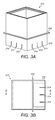
- Figures 3A-3E show perspective, elevation and sectional views of a first portion 310 of an outflow controller, that is arranged to work in cooperation with a second portion 320 of an outflow controller as shown in Figures 4A-4E to form an outflow controller 300 according to another example embodiment.
- the region indicated 312 in these figures serves as the connection between the first and second portions 310, 320.
- inlet openings 314 and a channel 318 to perform the function of the flow controlling restrictor.
- the embodiments described herein are intended for drainage of water (which herein includes aqueous based solutions as well as pure H 2 O) from a green roof, other related embodiments can also be envisaged as suitable for draining other fluids, including gasses, from other media and in other situations.
- the drainage system may also be usefully employed under block paving, car park decks or alternatively as a SUDS layer in the ground.
Landscapes
- Engineering & Computer Science (AREA)
- Architecture (AREA)
- Civil Engineering (AREA)
- Structural Engineering (AREA)
- Life Sciences & Earth Sciences (AREA)
- Health & Medical Sciences (AREA)
- Environmental & Geological Engineering (AREA)
- Hydrology & Water Resources (AREA)
- Public Health (AREA)
- Water Supply & Treatment (AREA)
- Sewage (AREA)
- Cultivation Of Plants (AREA)
- Underground Structures, Protecting, Testing And Restoring Foundations (AREA)
- Buildings Adapted To Withstand Abnormal External Influences (AREA)
Description
- The present invention relates to outflow controllers, for example such controllers that may comprise part of drainage structures. Example embodiments are particularly suited for use in drainage systems for roofs, including green roofs.
- One of the advantages of a green roof is the capacity of the roof to absorb rainwater and thereby reduce the peak flow of rainwater into subsequent drainage systems. This reduces the risk of flooding the subsequent drainage systems. The capacity to spread drainage load over time contributes to a sustainable drainage system (often referred to as SUDS).
- Problems arise when a green roof is not able to absorb rainwater as designed, for example if there are repeated heavy rainfall events in quick succession. In this situation the green roof may become saturated, which impacts on the SUDS performance. Building in additional capacity to cope with infrequent extreme rainfall events but without unduly increasing costs is a challenge.
- In addition, controlling the rate of outflow from a green roof, and maintaining consistent outflow performance over the lifetime of the green roof poses problems, for example due to silting up of the drainage pathways in the green roof. Problems with the outflow can also impact on SUDS performance.
- Furthermore, providing an outflow for a drainage system which is compatible with, and works effectively in any one of a range of different roof constructions is not straightforward.
-
WO 02/086253 A1 - Example embodiments of the present invention aim to address at least one disadvantage of the prior art, whether identified herein or otherwise.
- According to the present invention there is provided an apparatus and method as set forth in the appended claims. Other features of the invention will be apparent from the dependent claims, and the description which follows.
- For a better understanding of the invention, and to show how embodiments of the same may be carried into effect, reference will now be made, by way of example, to the accompanying diagrammatic drawings in which:
-
Figure 1 shows a side section view of a storage and attenuation structure and an outflow controller according to an example embodiment, arranged together in a drainage system; -
Figure 2 shows a side section view of the storage and attenuation structure ofFigure 1 , and an outflow controller according to another example embodiment, arranged together in a drainage system; -
Figures 3A-3E show perspective, elevation and sectional views of a first portion of an outflow controller according to an example embodiment; and -
Figures 4A-4E show perspective, elevation and sectional views of a second portion of an outflow controller according to an example embodiment. -
Figure 1 shows a side section view of a storage andattenuation structure 10 in use with anoutflow controller 100. Together the storage andattenuation structure 10 andoutflow controller 100 form part of a green roof structure which is provided above the structural elements of the roof R of a building. The green roof structure comprises vegetation V and a growth medium G. The roof R comprises a drain D to carry away excess rainwater from the green roof, after passage through the storage andattenuation structure 10 and theoutflow controller 100. Also shown inFigure 1 is insulation material for the roof, denoted as I, and which is provided in position which is above a fluid-impermeable membrane M so as to form what is referred to as in inverted green roof configuration. In this inverted green roof a further breathable,waterproof membrane 18 is provided to give a further degree of water resistance to the overall roof structure, and to enable any moisture which finds its way into the insulation, e.g. on installation before the insulation is overlaid, to permeate out. - The storage and
attenuation structure 10 is arranged to perform a number of functions. Firstly, it provides fluid storage, so that the growth medium G can be kept moist for longer and therefore providing better conditions for the vegetation V during periods where not much rain falls. Herein, the term "fluid" is generally to be understood as including any non-solid substance, for example liquids, gases, and combinations thereof, but in typical green roof applications the fluid will comprise water such as rain water, melt-water or the like. In addition to the storage of fluid to keep the growth medium G moist, the storage andattenuation structure 10 provides a SUDS function by buffering excess fluid and allowing that fluid to subsequently pass into the drain D over a relative longer period of time than if no storage orattenuation structure 10 was provided. - The storage and
attenuation structure 10 comprises anupper layer 11 for supporting the growth medium G above an upper side thereof. Growth medium G is kept above theupper layer 11 by a fluid-permeable barrier layer 19. Theupper layer 11 comprisesfluid storage recesses 13 to collect and store fluid received from above the upper side of theupper layer 11. The fluid storage recesses 13 in ofFigure 1 are in the form of downward pointing, truncated square-based pyramidal recesses, which are provided in regular arrangement across the surface of the sheet-likeupper layer 11. Between thefluid storage recesses 13 areopenings 15, formed is a border of material separatingadjacent storage recesses 13. Theopenings 15 are circular, and anopening 15 is provided at each corner of each of thefluid storage recesses 13. The fluid-permeable barrier layer 19 serves to keep theopenings 15 clear of growth medium G. - The
openings 15 are formed above thefluid storage recesses 13 in order to allow fluid communication between the upper side of theupper layer 11 and a lower side thereof. In this way, the vast majority of any rain water which passes down through the vegetation V and growth medium G is initially collected in thefluid storage recesses 13. Any overflow fluid from thestorage recesses 13 can drain through theopenings 15 and into alower layer 12 of the storage andattenuation structure 10. - The
lower layer 12 receives fluid from theupper layer 11, and includesdrainage pathways 14 to collect fluid received from theupper layer 11 and provide controlled drainage of that fluid. Thedrainage pathways 14 are formed between projections in thelower layer 12. Thedrainage pathways 14 are in fluid communication withspace 17 between thefluid storage recesses 13 in the upper layer, such that thespace 17 between thefluid storage recesses 13 provides additional fluid storage capacity beyond the capacity of thelower layer 12. In this way, when thedrainage pathways 14 are filled to the level of the top of thelower layer 12, for example after a period in which when the rate of supply of fluid through theopenings 15 exceeds the rate of drainage from thedrainage pathways 14, thespace 17 provides additional capacity storage capacity in the storage andattenuation structure 10 so that the peak flow from the storage andattenuation structure 10 is still smoothed. By using the space between thestorage recesses 13 in this way, the storage andattenuation structure 10 can be made inexpensively from existing types of drainage layers, and offers improved performance in case of the type of infrequent, but increasingly important extreme rainfall events. - The rate at which fluid may drain from the
drainage pathways 14 is controlled by theoutflow controller 100, as described in more detail below. - In
Figure 1 , theupper layer 11 and thelower layer 12 are separated by a fluid-permeable layer 16, with the compressive weight of the growth medium G and the vegetation V enough to hold the layers together. The fluid-permeable layer 16 may comprise a filter layer. However, it will be understood that in other embodiments the layers may be formed as an integrated single component or formed as separate components adhered, welded or otherwise coupled to one another after separate manufacture, with or without an intermediate layer. In another variation, not shown, thestorage recesses 13 in theupper layer 11 are coupled to their neighbours by load-sharing grooves arranged below the uppermost regions of the storage recesses, the load-sharing grooves arranged to enable fluid communication between adjacent storage recesses without the recesses overflowing to the level of theopenings 15. - The
outflow controller 100 operates to control release of fluid from the storage andattenuation structure 10 in a way which is principally dependent on the volume of fluid in thedrainage pathways 14 and in thespace 17 between thefluid storage recesses 13 in theupper layer 11. - Still referring to
Figure 1 , theoutflow controller 100 shown is made up of afirst portion 110 and asecond portion 120. Thefirst portion 110 comprises a flow controlling restrictor is and arranged to pass fluid received at the outflow controller through the flow controlling restrictor. Thesecond portion 120 comprises a drain component arranged to receive fluid that has passed through the flow controlling restrictor and to channel that fluid as outflow. Infigure 1 the first andsecond portions second portion connector 112. - By providing the first and second portions as separate components, referred to hereinafter as the first and
second components first component 110 can be supplied to be coupled to any one from a range ofsecond components 120 of differing dimensions. This way, manufacturing costs for theoutflow controller 100 can be reduced without impacting on the ease of installation in different drainage systems. For example, as will be explained in more detail below, thesecond component 120 passes through an opening the insulation I, and must allow theoutflow controller 100 to interface effectively with the drain D, insulation I and the elements above the insulation I from which drainage is required. In this case, differing depths of insulation required for particular installations may be accommodated by selecting a second component of suitable height between its base and the level of the edge of a layer to be drained. It should be noted that although theoutflow controller 100 has been shown in use with the storage and attenuation structure described above, it will be appreciated that theoutflow controller 100 may also be usefully employed in combination with other, for example, related-art storage and attenuation components or drainage components. The roof structure inFigures 1 and2 comprises an inverted green roof, but the growth medium and vegetation of the green roof may be substituted for ballast, paving etc in other roof structures, and the outflow controllers, and storage and attenuation structures described herein may equally find useful application in such roofs. - Furthermore, the single-pattern
first component 110 can be used in warm roof installations, in which the roof to be drained is insulated from below, within the structural elements of the roof structure, without the need for asecond component 120. This, in one aspect of the invention there is provided a first component comprising features as described herein, useful either in combination with a second component as described herein, or in combination with a roof drainage structure in which the first component cooperates directly with, for example rests on the roof surface to be drained. - The
second component 120 is arranged to interface, at its outer region, with thefirst component 110, and with fluid received at thefirst component 110. Thesecond component 120 is also arranged to interface, at its inner region, with thefirst component 110 and fluid that has passed through a flow controlling restrictor of theoutflow controller 100. This enables theoutflow controller 100 to give consistent fluid control performance, by using thesecond component 120 as part of the path into the outflow controller while separating the operation of the flow controlling restrictor from direct influence of the inlet to the outflow controller and the outlet of the outflow controller. - The
second component 120 comprises an insulation-interfacingregion 122 arranged to interface with the insulation I. The insulation-interfacingregion 122 comprises alip 124 under which the insulation I is received. The insulation-interfacingregion 122 comprises aflange 126, and the insulation is received in the space there-between. Theflange 122 sits above the fluid-impermeable membrane M. There is detail of this feature shown in the isometric detail insert A, whereseepage slots 127 are shown. Theseepage slots 127 are provided to enable moisture which does pass into the insulation I to escape under gravity. Also shown inFigure 1 and2 is aledge 134, which is formed on thefirst component 110 and is useful to keep the growth medium G out of theupper layer 11. The fluid-permeable barrier layer 19 which lies above theupper layer 11 can overlay theledge 134 and be joined there-to, for example by adhesive, to block growth medium G from entering theupper layer 11 around the edge of the fluid-permeable barrier layer 19. - The
lip 124 provides a collection surface to guide fluid received at theoutflow controller 100 to thefirst component 110 and thereby into the flow controlling restrictor. As shown inFigure 1 , thelip 124 comprises a collection channel 128 to hold fluid received at theoutflow controller 100 in the region of thefirst component 110. Also shown, in dotted lines, is a variation in which the lip comprises a blocking portion 124' arranged to inhibit passage of fluid received at theoutflow controller 100, through the connection between thesecond component 120 and thefirst component 110. - The
outflow controller 100 works to restrict passage of fluid from above the insulation layer to the drain D by employing a flow controlling restrictor. The flow controlling restrictor is formed as a structure comprising aninlet opening 114 and anoutlet opening 116. Between theinlet opening 114 and theoutlet opening 116 is achannel 118. Thechannel 118 is formed within thefirst component 110 and receives fluid which has passed into thefirst component 110 from theinlet opening 114. In the embodiments shown, theoutlet opening 116 operates to provide the controlled outflow from the second component. - The
channel 118 between theinlet opening 114 andoutlet opening 116 is open, such that if theoutlet opening 116 is blocked for whatever reason, thechannel 118 can still overflow, with overflow from thechannel 118 passing from thefirst component 110 to thesecond component 120 and then from thesecond component 120 as outflow to the drain D. Thechannel 118 shown inFigure 1 comprisesoverflow openings 119 positioned below the top of thechannel 118 to enable overflow from thechannel 118 before the channel is filled. However, it is advantageous for the level of the top of thechannel 118, or any overflow openings to be arranged above the level at which static pressure can cause fluid to overflow the channel, meaning that in normal use theoutlet opening 116 drains all of the fluid there-through, and the rate control provided by the flow controlling restrictor is dictated by theoutlet opening 116. - In the
channel 118, afilter 113 is provided arranged between theinlet opening 114 and theoutlet opening 116. Thechannel 118, and thefilter 113 it contains are accessible from an inspection opening in thefirst component 110. As shown inFigure 1 the inspection opening is sealed by alid 117. Thelid 117 is removable and re-sealable onto thefirst component 110 so as to enable thefilter 113 andchannel 118 to be inspected and replaced/cleaned as necessary. Using thefilter 113 as a secondary filtration element, after fluid is primarily filtered by the fluid-permeable layer 16, or the fluid-permeable layer 16 in combination with a fluid-permeable barrier layer 19 can give good filtration performance, down to particle sizes as low as 80-100 micrometres. The filter material and type are selected to give the required performance, according to requirements of the particular installation, for example in terms of porosity, flow rate, compatibility, efficiency, capacity etc. Furthermore, thechannel 118 provides a sump area below the level of theoutlet opening 116. This sump area acts as a silt trap for any larger particles which have passed into the flow controlling restrictor. The sump area serves to collect particles rather than allow them to pass out of the flow controlling restrictor. The sump area can be easily inspected for the presence of trapped silt, which is useful in identifying that there may be a problem in the installation. Furthermore the sump area can be easily accessed for cleaning if silt build-up is taking place. -
Figure 1 shows anoutflow controller 100 in which the flow controlling restrictor comprises a plurality ofinlet openings 114. In this embodiment the inlet openings are numerous and sufficient that they do not cause a significant restriction in fluid flow. However, the flow controlling restrictor comprises a morelimited outlet opening 116, illustrated inFigure 1 by twomain outlet openings 116. Theoutflow controller 100 ofFigure 1 is of generally rectangular section, when viewed in plan, with one main outlet opening per side to give four main outlet openings. In typical installations that are envisaged for the outflow controller a plurality of outflow openings, for example two, or ten or more may be provided. - The
outlet openings 116 are provided in the form of an adjustable opening, which can be varied in effective size, for example by a simple threaded stopper or other variable obstruction held there-in. In this way, adjustment of theoutlet opening 116 can be used to vary the flow rate from theoutflow controller 100. For example, in an initial installation a maximum nominal flow rate of 2.5 litres/second for each hectare to be drained may be specified. However, if environmental or other conditions change after installation it is possible to adjust the outlet opening to vary the flow rate, for example to reduce the maximum nominal flow rate down to 2 litres/second for each hectare to be drained. Typical outlet openings may be in the region of a few millimetres in diameter, up to 20mm or more. In other examples the adjustable opening may comprise a movable slide, flap or iris-diaphragm that can provide a variable obstruction to the opening, or may comprise a replaceable swap-in/swap-out restrictor in which opening component can be easily replaced with another with a larger or smaller effective restriction as required. - As with the
filter 113 andchannel 118, themain outlet openings 116 are accessible through the inspection opening, for example to enable the adjustable opening to be maintained or adjusted. - Finally in respect of
Figure 1 , there is shown anoverflow conduit 115 that provides a fluid communication path between the outside of the outflow controller and the drain D. The overflow conduit is at the level of the vegetation V to facilitate drainage thereof in the event of a blockage there-below, or in case of an exception extreme rainfall event. -
Figure 2 shows the storage and attenuation structure ofFigure 1 , and anoutflow controller 200 according to another example embodiment, arranged together in a drainage system. In contrast toFigure 1 , where the drain D is central and theoutflow controller 100 surrounds the drain D passing through the insulation I and the other layers,Figure 2 shows theoutflow controller 200 at the edge of a roof R coupled to an edge drain D'. There are some modifications to the first andsecond components outflow controller 200, as compared to the corresponding elements shown inFigure 1 , particularly in incorporating wall of thefirst component 210 as an interface with the edge drain D'. There is detail of this modification shown in the isometric detail insert B, in which slots are provided in the wall of thefirst component 210 to enable fluid to pass from thefirst component 210 into the drain D'. -
Figures 3A-3E show perspective, elevation and sectional views of afirst portion 310 of an outflow controller, that is arranged to work in cooperation with asecond portion 320 of an outflow controller as shown inFigures 4A-4E to form an outflow controller 300 according to another example embodiment. The region indicated 312 in these figures serves as the connection between the first andsecond portions limited inlet openings 314 and achannel 318 to perform the function of the flow controlling restrictor. - Although the embodiments described herein are intended for drainage of water (which herein includes aqueous based solutions as well as pure H2O) from a green roof, other related embodiments can also be envisaged as suitable for draining other fluids, including gasses, from other media and in other situations. In relation to drainage of water in a green roof, the drainage system may also be usefully employed under block paving, car park decks or alternatively as a SUDS layer in the ground.
Claims (15)
- An outflow controller comprising a first portion (110) and a second portion (120), the first portion (110) comprising a flow controlling restrictor and arranged to pass fluid received at the outflow controller through the flow controlling restrictor, and the second portion (120) comprising a drain component arranged to receive fluid that has passed through the flow controlling restrictor and to channel that fluid as outflow; characterised in that the flow controlling restrictor is formed as a structure comprising an inlet opening (114) and an outlet opening (116), with an open channel (118) between the inlet opening (114) and the outlet opening (118), arranged such that if the outlet opening (116) is blocked the channel (118) may overflow, with overflow from the channel (118) passing from the second portion (120) as outflow.
- The outflow controller of claim 1, wherein the channel (118) comprises one or more overflow (119) openings positioned below the top thereof, to enable overflow from the channel (118) before the channel (118) is filled.
- The outflow controller of claim 1 or 2, wherein the flow controlling restrictor comprises a filter element (113) arranged between the inlet opening (114) and the outlet opening (116).
- The outflow controller of claim 1, 2 or 3, wherein the channel (118), and/or filter element (113) are arranged to be accessible from an inspection opening in the first portion (110).
- The outflow controller of any one of claims 1 to 4, comprising one or more main outlet openings (116), with one of more of the main outlet openings (116) provided in the form of an adjustable opening.
- The outflow controller of any one of claims 1 to 5, wherein the second portion (120) comprises an insulation-interfacing region (122) arranged to interface with an insulation layer in use with the outflow controller, the insulation-interfacing region (122) comprising a lip (124) under which insulation is in use received.
- The outflow controller of claim 6, wherein the insulation-interfacing region (122) comprises a space between a lip (124) and a flange (126), into which insulation is in use received.
- The outflow controller of claim 7, wherein the lip (124) is arranged to provide a collection surface to guide fluid received at the outflow controller to the first portion (110).
- The outflow controller of any one of claims 1 to 8, wherein the first portion (110) comprises part of a first component and the second portion (120) comprises part of a second component, the separate components coupled to one another in the outflow controller.
- The outflow controller of claim 9, wherein the first portion comprises an overflow conduit (115) that provides a fluid communication path between the outside of the flow controlling component and a drain component, wherein the overflow conduit (115) is arranged above the flow controlling restrictor.
- The outflow controller of claim 9 or 10, wherein the second component is arranged to interface at an outer region with the first component and fluid received at the first component, and to interface at an inner region with the first component and fluid that has passed through the flow controlling restrictor.
- The outflow controller of any one of claims 1 to 11, wherein the flow controlling restrictor comprises a seepage opening (127) arranged to work with a main outlet opening (116) to enable a small amount of seepage to take place through the flow controlling restrictor.
- The outflow controller of any one of claims 1 to 12, wherein the flow controlling restrictor comprises a sump area arranged below main outlet opening(s) (116), arranged to collect particles from fluid as it flows from the inlet opening to a main outlet opening (116).
- The outflow controller of any one of claims 1 to 13, wherein the main outlet opening (116), and any adjustable opening it contains, is arranged to be accessible from an inspection opening in the first portion (110).
- The outflow controller of any one of claims 1 to 14, wherein the inlet opening (114) is less restrictive to flow than the outlet opening (116), for example such that the inlet causes a negligible restriction to flow.
Priority Applications (1)
| Application Number | Priority Date | Filing Date | Title |
|---|---|---|---|
| PL13728791T PL2867423T3 (en) | 2012-05-28 | 2013-05-28 | Improvements in and relating to drainage systems |
Applications Claiming Priority (2)
| Application Number | Priority Date | Filing Date | Title |
|---|---|---|---|
| GB1209435.5A GB2504450B (en) | 2012-05-28 | 2012-05-28 | Drainage system with adjustable flow restrictor |
| PCT/GB2013/051413 WO2013179022A2 (en) | 2012-05-28 | 2013-05-28 | Improvements in and relating to drainage systems |
Publications (2)
| Publication Number | Publication Date |
|---|---|
| EP2867423A2 EP2867423A2 (en) | 2015-05-06 |
| EP2867423B1 true EP2867423B1 (en) | 2016-11-02 |
Family
ID=46546055
Family Applications (1)
| Application Number | Title | Priority Date | Filing Date |
|---|---|---|---|
| EP13728791.8A Active EP2867423B1 (en) | 2012-05-28 | 2013-05-28 | Improvements in and relating to drainage systems |
Country Status (8)
| Country | Link |
|---|---|
| EP (1) | EP2867423B1 (en) |
| AU (1) | AU2013269305B2 (en) |
| CA (1) | CA2874909A1 (en) |
| ES (1) | ES2614239T3 (en) |
| GB (1) | GB2504450B (en) |
| PL (1) | PL2867423T3 (en) |
| WO (1) | WO2013179022A2 (en) |
| ZA (1) | ZA201409173B (en) |
Families Citing this family (3)
| Publication number | Priority date | Publication date | Assignee | Title |
|---|---|---|---|---|
| CN105089302B (en) * | 2015-07-17 | 2017-12-01 | 上海交通大学 | A kind of Rain Garden system for the shunting of community's rainwater, peak clipping and ecological purification |
| NO343128B1 (en) * | 2016-08-23 | 2018-11-12 | Protan As | Apparatus for draining water from a flat roof or part of a flat roof structure with some slope, and use of such a device. |
| JP7849794B2 (en) * | 2022-07-21 | 2026-04-22 | 田島ルーフィング株式会社 | Rooftop greening rainwater temporary storage system |
Family Cites Families (10)
| Publication number | Priority date | Publication date | Assignee | Title |
|---|---|---|---|---|
| AU7947201A (en) * | 2000-11-02 | 2002-05-09 | Geberit Technik Ag | Roof drainage system and process for roof draining |
| EP1251218A1 (en) * | 2001-04-21 | 2002-10-23 | Bert Dautzenberg | A device for collecting and storing water from the environment |
| CA2403610A1 (en) * | 2002-09-17 | 2004-03-17 | Premier Tech 2000 Ltee | Buoyancy flushing apparatus and method thereof |
| WO2007113562A1 (en) * | 2006-04-04 | 2007-10-11 | Ampteam Assets Limited | Precipitation management system |
| DE202007006044U1 (en) * | 2007-04-25 | 2007-08-02 | Zinco Gmbh | Interconnectable drainage plates with integrated protection function |
| US20090188172A1 (en) * | 2008-01-24 | 2009-07-30 | Carlisle Intangible Company | Ballasted storm water retention system |
| US8479443B2 (en) * | 2008-04-29 | 2013-07-09 | Bioroof Systems Inc. | Green roof system with biodegradable vegetation tray |
| EP2172096A1 (en) * | 2008-10-06 | 2010-04-07 | Toan Dang Vu | Roof with modular plant cover |
| US8272163B2 (en) * | 2010-02-12 | 2012-09-25 | Metro Green Visions, Inc. | Modular interlocking pre-vegetated roof system |
| GB2484739B (en) * | 2010-10-22 | 2018-01-31 | A B G Ltd | Drainage system |
-
2012
- 2012-05-28 GB GB1209435.5A patent/GB2504450B/en active Active
-
2013
- 2013-05-28 ES ES13728791.8T patent/ES2614239T3/en active Active
- 2013-05-28 AU AU2013269305A patent/AU2013269305B2/en not_active Ceased
- 2013-05-28 EP EP13728791.8A patent/EP2867423B1/en active Active
- 2013-05-28 PL PL13728791T patent/PL2867423T3/en unknown
- 2013-05-28 CA CA2874909A patent/CA2874909A1/en not_active Abandoned
- 2013-05-28 WO PCT/GB2013/051413 patent/WO2013179022A2/en not_active Ceased
-
2014
- 2014-12-12 ZA ZA2014/09173A patent/ZA201409173B/en unknown
Also Published As
| Publication number | Publication date |
|---|---|
| WO2013179022A2 (en) | 2013-12-05 |
| GB2504450A (en) | 2014-02-05 |
| EP2867423A2 (en) | 2015-05-06 |
| CA2874909A1 (en) | 2013-12-05 |
| PL2867423T3 (en) | 2017-05-31 |
| GB201209435D0 (en) | 2012-07-11 |
| WO2013179022A3 (en) | 2014-05-15 |
| AU2013269305B2 (en) | 2016-09-22 |
| AU2013269305A1 (en) | 2015-01-15 |
| GB2504450B (en) | 2018-08-29 |
| ZA201409173B (en) | 2016-04-28 |
| ES2614239T3 (en) | 2017-05-30 |
Similar Documents
| Publication | Publication Date | Title |
|---|---|---|
| CN104220680B (en) | Apparatus and method for filtering rainwater | |
| US20080179229A1 (en) | Filter assembly for use in drainage system | |
| US8623204B2 (en) | Stormwater gully | |
| TW201114990A (en) | Rainwater filtering device for inflow path | |
| JP6013893B2 (en) | Rainwater storage piping structure | |
| AU2013269305B2 (en) | Improvements in and relating to drainage systems | |
| CN112105787A (en) | Packing drainage ditch unit, packing drainage ditch system and well element | |
| JP4861076B2 (en) | Rainwater collector | |
| EP2630313B1 (en) | Drainage system | |
| JP5866221B2 (en) | Rainwater treatment facility | |
| US20130264258A1 (en) | Stormwater treatment device | |
| EP2443291B1 (en) | Drainage system having vortex brake | |
| JP6371625B2 (en) | Rainwater storage and penetration facility | |
| JPH08193393A (en) | Drainage equipment structure in balcony | |
| GB2558832A (en) | Improvements in and relating to drainage systems | |
| KR20120091683A (en) | Roof drain cap and temporary reservoir structure | |
| KR20170079458A (en) | Simple rainwater filter hanging under a grating | |
| EP3064668B1 (en) | System for regulating the flow of water | |
| JP2011247014A (en) | Rainwater outflow restraining facility | |
| JP2012072598A (en) | Rainwater disposal facility | |
| US20200246727A1 (en) | Up-Flow Water Filtration System | |
| KR101564958B1 (en) | Rainwater receiving case improved drainage efficiency and water-permeability | |
| KR101528834B1 (en) | Jointed facilities keeping rainwater using block having incline and detachable filter element | |
| CN221989512U (en) | Rainwater collecting and discharging device suitable for sinking green land | |
| CN116837907B (en) | A kind of basement waterproof structure and its use method |
Legal Events
| Date | Code | Title | Description |
|---|---|---|---|
| PUAI | Public reference made under article 153(3) epc to a published international application that has entered the european phase |
Free format text: ORIGINAL CODE: 0009012 |
|
| 17P | Request for examination filed |
Effective date: 20141203 |
|
| AK | Designated contracting states |
Kind code of ref document: A2 Designated state(s): AL AT BE BG CH CY CZ DE DK EE ES FI FR GB GR HR HU IE IS IT LI LT LU LV MC MK MT NL NO PL PT RO RS SE SI SK SM TR |
|
| AX | Request for extension of the european patent |
Extension state: BA ME |
|
| DAX | Request for extension of the european patent (deleted) | ||
| GRAP | Despatch of communication of intention to grant a patent |
Free format text: ORIGINAL CODE: EPIDOSNIGR1 |
|
| INTG | Intention to grant announced |
Effective date: 20160525 |
|
| GRAS | Grant fee paid |
Free format text: ORIGINAL CODE: EPIDOSNIGR3 |
|
| GRAA | (expected) grant |
Free format text: ORIGINAL CODE: 0009210 |
|
| AK | Designated contracting states |
Kind code of ref document: B1 Designated state(s): AL AT BE BG CH CY CZ DE DK EE ES FI FR GB GR HR HU IE IS IT LI LT LU LV MC MK MT NL NO PL PT RO RS SE SI SK SM TR |
|
| REG | Reference to a national code |
Ref country code: GB Ref legal event code: FG4D |
|
| REG | Reference to a national code |
Ref country code: AT Ref legal event code: REF Ref document number: 842018 Country of ref document: AT Kind code of ref document: T Effective date: 20161115 Ref country code: CH Ref legal event code: EP |
|
| REG | Reference to a national code |
Ref country code: IE Ref legal event code: FG4D |
|
| REG | Reference to a national code |
Ref country code: DE Ref legal event code: R096 Ref document number: 602013013492 Country of ref document: DE |
|
| REG | Reference to a national code |
Ref country code: NL Ref legal event code: FP |
|
| REG | Reference to a national code |
Ref country code: SE Ref legal event code: TRGR |
|
| PG25 | Lapsed in a contracting state [announced via postgrant information from national office to epo] |
Ref country code: LV Free format text: LAPSE BECAUSE OF FAILURE TO SUBMIT A TRANSLATION OF THE DESCRIPTION OR TO PAY THE FEE WITHIN THE PRESCRIBED TIME-LIMIT Effective date: 20161102 |
|
| REG | Reference to a national code |
Ref country code: LT Ref legal event code: MG4D |
|
| REG | Reference to a national code |
Ref country code: NO Ref legal event code: T2 Effective date: 20161102 |
|
| PG25 | Lapsed in a contracting state [announced via postgrant information from national office to epo] |
Ref country code: GR Free format text: LAPSE BECAUSE OF FAILURE TO SUBMIT A TRANSLATION OF THE DESCRIPTION OR TO PAY THE FEE WITHIN THE PRESCRIBED TIME-LIMIT Effective date: 20170203 Ref country code: LT Free format text: LAPSE BECAUSE OF FAILURE TO SUBMIT A TRANSLATION OF THE DESCRIPTION OR TO PAY THE FEE WITHIN THE PRESCRIBED TIME-LIMIT Effective date: 20161102 |
|
| REG | Reference to a national code |
Ref country code: ES Ref legal event code: FG2A Ref document number: 2614239 Country of ref document: ES Kind code of ref document: T3 Effective date: 20170530 |
|
| PG25 | Lapsed in a contracting state [announced via postgrant information from national office to epo] |
Ref country code: PT Free format text: LAPSE BECAUSE OF FAILURE TO SUBMIT A TRANSLATION OF THE DESCRIPTION OR TO PAY THE FEE WITHIN THE PRESCRIBED TIME-LIMIT Effective date: 20170302 Ref country code: RS Free format text: LAPSE BECAUSE OF FAILURE TO SUBMIT A TRANSLATION OF THE DESCRIPTION OR TO PAY THE FEE WITHIN THE PRESCRIBED TIME-LIMIT Effective date: 20161102 Ref country code: IS Free format text: LAPSE BECAUSE OF FAILURE TO SUBMIT A TRANSLATION OF THE DESCRIPTION OR TO PAY THE FEE WITHIN THE PRESCRIBED TIME-LIMIT Effective date: 20170302 Ref country code: FI Free format text: LAPSE BECAUSE OF FAILURE TO SUBMIT A TRANSLATION OF THE DESCRIPTION OR TO PAY THE FEE WITHIN THE PRESCRIBED TIME-LIMIT Effective date: 20161102 Ref country code: HR Free format text: LAPSE BECAUSE OF FAILURE TO SUBMIT A TRANSLATION OF THE DESCRIPTION OR TO PAY THE FEE WITHIN THE PRESCRIBED TIME-LIMIT Effective date: 20161102 |
|
| PG25 | Lapsed in a contracting state [announced via postgrant information from national office to epo] |
Ref country code: RO Free format text: LAPSE BECAUSE OF FAILURE TO SUBMIT A TRANSLATION OF THE DESCRIPTION OR TO PAY THE FEE WITHIN THE PRESCRIBED TIME-LIMIT Effective date: 20161102 Ref country code: EE Free format text: LAPSE BECAUSE OF FAILURE TO SUBMIT A TRANSLATION OF THE DESCRIPTION OR TO PAY THE FEE WITHIN THE PRESCRIBED TIME-LIMIT Effective date: 20161102 Ref country code: DK Free format text: LAPSE BECAUSE OF FAILURE TO SUBMIT A TRANSLATION OF THE DESCRIPTION OR TO PAY THE FEE WITHIN THE PRESCRIBED TIME-LIMIT Effective date: 20161102 Ref country code: SK Free format text: LAPSE BECAUSE OF FAILURE TO SUBMIT A TRANSLATION OF THE DESCRIPTION OR TO PAY THE FEE WITHIN THE PRESCRIBED TIME-LIMIT Effective date: 20161102 |
|
| REG | Reference to a national code |
Ref country code: DE Ref legal event code: R097 Ref document number: 602013013492 Country of ref document: DE |
|
| REG | Reference to a national code |
Ref country code: FR Ref legal event code: PLFP Year of fee payment: 5 |
|
| PG25 | Lapsed in a contracting state [announced via postgrant information from national office to epo] |
Ref country code: BG Free format text: LAPSE BECAUSE OF FAILURE TO SUBMIT A TRANSLATION OF THE DESCRIPTION OR TO PAY THE FEE WITHIN THE PRESCRIBED TIME-LIMIT Effective date: 20170202 Ref country code: SM Free format text: LAPSE BECAUSE OF FAILURE TO SUBMIT A TRANSLATION OF THE DESCRIPTION OR TO PAY THE FEE WITHIN THE PRESCRIBED TIME-LIMIT Effective date: 20161102 |
|
| PLBE | No opposition filed within time limit |
Free format text: ORIGINAL CODE: 0009261 |
|
| STAA | Information on the status of an ep patent application or granted ep patent |
Free format text: STATUS: NO OPPOSITION FILED WITHIN TIME LIMIT |
|
| 26N | No opposition filed |
Effective date: 20170803 |
|
| PG25 | Lapsed in a contracting state [announced via postgrant information from national office to epo] |
Ref country code: SI Free format text: LAPSE BECAUSE OF FAILURE TO SUBMIT A TRANSLATION OF THE DESCRIPTION OR TO PAY THE FEE WITHIN THE PRESCRIBED TIME-LIMIT Effective date: 20161102 |
|
| PG25 | Lapsed in a contracting state [announced via postgrant information from national office to epo] |
Ref country code: MC Free format text: LAPSE BECAUSE OF FAILURE TO SUBMIT A TRANSLATION OF THE DESCRIPTION OR TO PAY THE FEE WITHIN THE PRESCRIBED TIME-LIMIT Effective date: 20161102 |
|
| REG | Reference to a national code |
Ref country code: FR Ref legal event code: PLFP Year of fee payment: 6 |
|
| PG25 | Lapsed in a contracting state [announced via postgrant information from national office to epo] |
Ref country code: MT Free format text: LAPSE BECAUSE OF NON-PAYMENT OF DUE FEES Effective date: 20170528 |
|
| REG | Reference to a national code |
Ref country code: AT Ref legal event code: UEP Ref document number: 842018 Country of ref document: AT Kind code of ref document: T Effective date: 20161102 |
|
| PG25 | Lapsed in a contracting state [announced via postgrant information from national office to epo] |
Ref country code: HU Free format text: LAPSE BECAUSE OF FAILURE TO SUBMIT A TRANSLATION OF THE DESCRIPTION OR TO PAY THE FEE WITHIN THE PRESCRIBED TIME-LIMIT; INVALID AB INITIO Effective date: 20130528 |
|
| PG25 | Lapsed in a contracting state [announced via postgrant information from national office to epo] |
Ref country code: CY Free format text: LAPSE BECAUSE OF FAILURE TO SUBMIT A TRANSLATION OF THE DESCRIPTION OR TO PAY THE FEE WITHIN THE PRESCRIBED TIME-LIMIT Effective date: 20161102 |
|
| PG25 | Lapsed in a contracting state [announced via postgrant information from national office to epo] |
Ref country code: MK Free format text: LAPSE BECAUSE OF FAILURE TO SUBMIT A TRANSLATION OF THE DESCRIPTION OR TO PAY THE FEE WITHIN THE PRESCRIBED TIME-LIMIT Effective date: 20161102 |
|
| PG25 | Lapsed in a contracting state [announced via postgrant information from national office to epo] |
Ref country code: AL Free format text: LAPSE BECAUSE OF FAILURE TO SUBMIT A TRANSLATION OF THE DESCRIPTION OR TO PAY THE FEE WITHIN THE PRESCRIBED TIME-LIMIT Effective date: 20161102 |
|
| PGFP | Annual fee paid to national office [announced via postgrant information from national office to epo] |
Ref country code: CZ Payment date: 20210521 Year of fee payment: 9 Ref country code: NO Payment date: 20210521 Year of fee payment: 9 |
|
| PGFP | Annual fee paid to national office [announced via postgrant information from national office to epo] |
Ref country code: SE Payment date: 20210519 Year of fee payment: 9 Ref country code: PL Payment date: 20210524 Year of fee payment: 9 Ref country code: AT Payment date: 20210520 Year of fee payment: 9 Ref country code: TR Payment date: 20210525 Year of fee payment: 9 Ref country code: CH Payment date: 20210519 Year of fee payment: 9 |
|
| REG | Reference to a national code |
Ref country code: NO Ref legal event code: MMEP |
|
| REG | Reference to a national code |
Ref country code: CH Ref legal event code: PL |
|
| REG | Reference to a national code |
Ref country code: SE Ref legal event code: EUG |
|
| REG | Reference to a national code |
Ref country code: AT Ref legal event code: MM01 Ref document number: 842018 Country of ref document: AT Kind code of ref document: T Effective date: 20220528 |
|
| PG25 | Lapsed in a contracting state [announced via postgrant information from national office to epo] |
Ref country code: SE Free format text: LAPSE BECAUSE OF NON-PAYMENT OF DUE FEES Effective date: 20220529 Ref country code: NO Free format text: LAPSE BECAUSE OF NON-PAYMENT OF DUE FEES Effective date: 20220531 Ref country code: LI Free format text: LAPSE BECAUSE OF NON-PAYMENT OF DUE FEES Effective date: 20220531 Ref country code: CZ Free format text: LAPSE BECAUSE OF NON-PAYMENT OF DUE FEES Effective date: 20220528 Ref country code: CH Free format text: LAPSE BECAUSE OF NON-PAYMENT OF DUE FEES Effective date: 20220531 Ref country code: AT Free format text: LAPSE BECAUSE OF NON-PAYMENT OF DUE FEES Effective date: 20220528 |
|
| PG25 | Lapsed in a contracting state [announced via postgrant information from national office to epo] |
Ref country code: PL Free format text: LAPSE BECAUSE OF NON-PAYMENT OF DUE FEES Effective date: 20220528 |
|
| PGFP | Annual fee paid to national office [announced via postgrant information from national office to epo] |
Ref country code: NL Payment date: 20250521 Year of fee payment: 13 |
|
| PGFP | Annual fee paid to national office [announced via postgrant information from national office to epo] |
Ref country code: DE Payment date: 20250521 Year of fee payment: 13 |
|
| PGFP | Annual fee paid to national office [announced via postgrant information from national office to epo] |
Ref country code: GB Payment date: 20250521 Year of fee payment: 13 Ref country code: ES Payment date: 20250627 Year of fee payment: 13 |
|
| PGFP | Annual fee paid to national office [announced via postgrant information from national office to epo] |
Ref country code: LU Payment date: 20250521 Year of fee payment: 13 Ref country code: BE Payment date: 20250521 Year of fee payment: 13 Ref country code: IT Payment date: 20250527 Year of fee payment: 13 |
|
| PGFP | Annual fee paid to national office [announced via postgrant information from national office to epo] |
Ref country code: FR Payment date: 20250528 Year of fee payment: 13 |
|
| PGFP | Annual fee paid to national office [announced via postgrant information from national office to epo] |
Ref country code: IE Payment date: 20250521 Year of fee payment: 13 |