EP2866920B1 - A sorption drying system - Google Patents
A sorption drying system Download PDFInfo
- Publication number
- EP2866920B1 EP2866920B1 EP13771644.5A EP13771644A EP2866920B1 EP 2866920 B1 EP2866920 B1 EP 2866920B1 EP 13771644 A EP13771644 A EP 13771644A EP 2866920 B1 EP2866920 B1 EP 2866920B1
- Authority
- EP
- European Patent Office
- Prior art keywords
- gas stream
- sector
- drying
- rotor
- partial
- Prior art date
- Legal status (The legal status is an assumption and is not a legal conclusion. Google has not performed a legal analysis and makes no representation as to the accuracy of the status listed.)
- Active
Links
Images



Classifications
-
- B—PERFORMING OPERATIONS; TRANSPORTING
- B01—PHYSICAL OR CHEMICAL PROCESSES OR APPARATUS IN GENERAL
- B01D—SEPARATION
- B01D53/00—Separation of gases or vapours; Recovering vapours of volatile solvents from gases; Chemical or biological purification of waste gases, e.g. engine exhaust gases, smoke, fumes, flue gases, aerosols
- B01D53/26—Drying gases or vapours
- B01D53/261—Drying gases or vapours by adsorption
-
- B—PERFORMING OPERATIONS; TRANSPORTING
- B01—PHYSICAL OR CHEMICAL PROCESSES OR APPARATUS IN GENERAL
- B01D—SEPARATION
- B01D53/00—Separation of gases or vapours; Recovering vapours of volatile solvents from gases; Chemical or biological purification of waste gases, e.g. engine exhaust gases, smoke, fumes, flue gases, aerosols
- B01D53/26—Drying gases or vapours
- B01D53/263—Drying gases or vapours by absorption
-
- B—PERFORMING OPERATIONS; TRANSPORTING
- B01—PHYSICAL OR CHEMICAL PROCESSES OR APPARATUS IN GENERAL
- B01D—SEPARATION
- B01D53/00—Separation of gases or vapours; Recovering vapours of volatile solvents from gases; Chemical or biological purification of waste gases, e.g. engine exhaust gases, smoke, fumes, flue gases, aerosols
- B01D53/02—Separation of gases or vapours; Recovering vapours of volatile solvents from gases; Chemical or biological purification of waste gases, e.g. engine exhaust gases, smoke, fumes, flue gases, aerosols by adsorption, e.g. preparative gas chromatography
- B01D53/06—Separation of gases or vapours; Recovering vapours of volatile solvents from gases; Chemical or biological purification of waste gases, e.g. engine exhaust gases, smoke, fumes, flue gases, aerosols by adsorption, e.g. preparative gas chromatography with moving adsorbents, e.g. rotating beds
-
- F—MECHANICAL ENGINEERING; LIGHTING; HEATING; WEAPONS; BLASTING
- F24—HEATING; RANGES; VENTILATING
- F24F—AIR-CONDITIONING; AIR-HUMIDIFICATION; VENTILATION; USE OF AIR CURRENTS FOR SCREENING
- F24F3/00—Air-conditioning systems in which conditioned primary air is supplied from one or more central stations to distributing units in the rooms or spaces where it may receive secondary treatment; Apparatus specially designed for such systems
- F24F3/12—Air-conditioning systems in which conditioned primary air is supplied from one or more central stations to distributing units in the rooms or spaces where it may receive secondary treatment; Apparatus specially designed for such systems characterised by the treatment of the air otherwise than by heating and cooling
- F24F3/14—Air-conditioning systems in which conditioned primary air is supplied from one or more central stations to distributing units in the rooms or spaces where it may receive secondary treatment; Apparatus specially designed for such systems characterised by the treatment of the air otherwise than by heating and cooling by humidification; by dehumidification
-
- F—MECHANICAL ENGINEERING; LIGHTING; HEATING; WEAPONS; BLASTING
- F24—HEATING; RANGES; VENTILATING
- F24F—AIR-CONDITIONING; AIR-HUMIDIFICATION; VENTILATION; USE OF AIR CURRENTS FOR SCREENING
- F24F3/00—Air-conditioning systems in which conditioned primary air is supplied from one or more central stations to distributing units in the rooms or spaces where it may receive secondary treatment; Apparatus specially designed for such systems
- F24F3/12—Air-conditioning systems in which conditioned primary air is supplied from one or more central stations to distributing units in the rooms or spaces where it may receive secondary treatment; Apparatus specially designed for such systems characterised by the treatment of the air otherwise than by heating and cooling
- F24F3/14—Air-conditioning systems in which conditioned primary air is supplied from one or more central stations to distributing units in the rooms or spaces where it may receive secondary treatment; Apparatus specially designed for such systems characterised by the treatment of the air otherwise than by heating and cooling by humidification; by dehumidification
- F24F3/1405—Air-conditioning systems in which conditioned primary air is supplied from one or more central stations to distributing units in the rooms or spaces where it may receive secondary treatment; Apparatus specially designed for such systems characterised by the treatment of the air otherwise than by heating and cooling by humidification; by dehumidification in which the humidity of the air is exclusively affected by contact with the evaporator of a closed-circuit cooling system or heat pump circuit
-
- F—MECHANICAL ENGINEERING; LIGHTING; HEATING; WEAPONS; BLASTING
- F24—HEATING; RANGES; VENTILATING
- F24F—AIR-CONDITIONING; AIR-HUMIDIFICATION; VENTILATION; USE OF AIR CURRENTS FOR SCREENING
- F24F3/00—Air-conditioning systems in which conditioned primary air is supplied from one or more central stations to distributing units in the rooms or spaces where it may receive secondary treatment; Apparatus specially designed for such systems
- F24F3/12—Air-conditioning systems in which conditioned primary air is supplied from one or more central stations to distributing units in the rooms or spaces where it may receive secondary treatment; Apparatus specially designed for such systems characterised by the treatment of the air otherwise than by heating and cooling
- F24F3/14—Air-conditioning systems in which conditioned primary air is supplied from one or more central stations to distributing units in the rooms or spaces where it may receive secondary treatment; Apparatus specially designed for such systems characterised by the treatment of the air otherwise than by heating and cooling by humidification; by dehumidification
- F24F3/1411—Air-conditioning systems in which conditioned primary air is supplied from one or more central stations to distributing units in the rooms or spaces where it may receive secondary treatment; Apparatus specially designed for such systems characterised by the treatment of the air otherwise than by heating and cooling by humidification; by dehumidification by absorbing or adsorbing water, e.g. using an hygroscopic desiccant
- F24F3/1423—Air-conditioning systems in which conditioned primary air is supplied from one or more central stations to distributing units in the rooms or spaces where it may receive secondary treatment; Apparatus specially designed for such systems characterised by the treatment of the air otherwise than by heating and cooling by humidification; by dehumidification by absorbing or adsorbing water, e.g. using an hygroscopic desiccant with a moving bed of solid desiccants, e.g. a rotary wheel supporting solid desiccants
-
- B—PERFORMING OPERATIONS; TRANSPORTING
- B01—PHYSICAL OR CHEMICAL PROCESSES OR APPARATUS IN GENERAL
- B01D—SEPARATION
- B01D2253/00—Adsorbents used in seperation treatment of gases and vapours
- B01D2253/10—Inorganic adsorbents
- B01D2253/106—Silica or silicates
-
- B—PERFORMING OPERATIONS; TRANSPORTING
- B01—PHYSICAL OR CHEMICAL PROCESSES OR APPARATUS IN GENERAL
- B01D—SEPARATION
- B01D2253/00—Adsorbents used in seperation treatment of gases and vapours
- B01D2253/10—Inorganic adsorbents
- B01D2253/106—Silica or silicates
- B01D2253/108—Zeolites
-
- B—PERFORMING OPERATIONS; TRANSPORTING
- B01—PHYSICAL OR CHEMICAL PROCESSES OR APPARATUS IN GENERAL
- B01D—SEPARATION
- B01D2257/00—Components to be removed
- B01D2257/50—Carbon oxides
- B01D2257/502—Carbon monoxide
-
- B—PERFORMING OPERATIONS; TRANSPORTING
- B01—PHYSICAL OR CHEMICAL PROCESSES OR APPARATUS IN GENERAL
- B01D—SEPARATION
- B01D2257/00—Components to be removed
- B01D2257/50—Carbon oxides
- B01D2257/504—Carbon dioxide
-
- B—PERFORMING OPERATIONS; TRANSPORTING
- B01—PHYSICAL OR CHEMICAL PROCESSES OR APPARATUS IN GENERAL
- B01D—SEPARATION
- B01D2257/00—Components to be removed
- B01D2257/70—Organic compounds not provided for in groups B01D2257/00 - B01D2257/602
- B01D2257/708—Volatile organic compounds V.O.C.'s
-
- B—PERFORMING OPERATIONS; TRANSPORTING
- B01—PHYSICAL OR CHEMICAL PROCESSES OR APPARATUS IN GENERAL
- B01D—SEPARATION
- B01D2257/00—Components to be removed
- B01D2257/80—Water
-
- B—PERFORMING OPERATIONS; TRANSPORTING
- B01—PHYSICAL OR CHEMICAL PROCESSES OR APPARATUS IN GENERAL
- B01D—SEPARATION
- B01D2259/00—Type of treatment
- B01D2259/40—Further details for adsorption processes and devices
- B01D2259/40083—Regeneration of adsorbents in processes other than pressure or temperature swing adsorption
- B01D2259/40088—Regeneration of adsorbents in processes other than pressure or temperature swing adsorption by heating
-
- F—MECHANICAL ENGINEERING; LIGHTING; HEATING; WEAPONS; BLASTING
- F24—HEATING; RANGES; VENTILATING
- F24F—AIR-CONDITIONING; AIR-HUMIDIFICATION; VENTILATION; USE OF AIR CURRENTS FOR SCREENING
- F24F2203/00—Devices or apparatus used for air treatment
- F24F2203/10—Rotary wheel
- F24F2203/1016—Rotary wheel combined with another type of cooling principle, e.g. compression cycle
-
- F—MECHANICAL ENGINEERING; LIGHTING; HEATING; WEAPONS; BLASTING
- F24—HEATING; RANGES; VENTILATING
- F24F—AIR-CONDITIONING; AIR-HUMIDIFICATION; VENTILATION; USE OF AIR CURRENTS FOR SCREENING
- F24F2203/00—Devices or apparatus used for air treatment
- F24F2203/10—Rotary wheel
- F24F2203/1032—Desiccant wheel
-
- Y—GENERAL TAGGING OF NEW TECHNOLOGICAL DEVELOPMENTS; GENERAL TAGGING OF CROSS-SECTIONAL TECHNOLOGIES SPANNING OVER SEVERAL SECTIONS OF THE IPC; TECHNICAL SUBJECTS COVERED BY FORMER USPC CROSS-REFERENCE ART COLLECTIONS [XRACs] AND DIGESTS
- Y02—TECHNOLOGIES OR APPLICATIONS FOR MITIGATION OR ADAPTATION AGAINST CLIMATE CHANGE
- Y02C—CAPTURE, STORAGE, SEQUESTRATION OR DISPOSAL OF GREENHOUSE GASES [GHG]
- Y02C20/00—Capture or disposal of greenhouse gases
- Y02C20/40—Capture or disposal of greenhouse gases of CO2
Definitions
- a controlled recirculation or return of the cooled deflected dehumidified gas stream is achieved. This means that the flow rate or the air flow of the cooled dehumidified gas stream can be increased so that it efficiently cools down the drying rotor.
- At least a part of the cooled dehumidified gas stream flows through the drying rotor in a channel separated from the moist gas stream by means of seals.
- the means for deflection comprises a fan situated between the outlet of the dehumidified gas stream from the drying rotor and the cooler.
- the means for deflection comprises a fan situated between the cooler and the inlet of the moist gas stream into the drying rotor.
- the absorbent mass is in the form of a rotor and is adapted to rotate about a central axis, the moist gas stream being adapted to flow through a first channel of the rotor and the stream of regeneration gas being adapted to flow through a second channel of the rotor, separated from the first channel by means of seals, and the channels essentially having the shape of circular sectors.
- the deflection of the dehumidified gas stream occurs in a partial circular sector situated essentially immediately after the circular sector of the stream of regeneration gas in the direction of rotation of the absorbent rotor.
- the deflection of the dehumidified gas stream also occurs in a partial circular sector situated essentially immediately before the circular sector of the stream of regeneration gas in the direction of rotation of the absorbent disc.
- the sorption drying system comprises a valve situated at the outlet or outlet from the drying rotor of the stream of regeneration gas for regulating the pressure of the stream of regeneration gas.
- the sorption drying system comprises a fan for varying the flow of the stream of regeneration gas through the drying rotor.
- the parts of the drying system that comprise the absorbent mass and its seals are built-in in an air-proof housing.
- the present invention concerns a method for dehumidification of a gas stream in a sorption drying system comprising a mass of absorbing material in the form of a drying rotor that is adapted to rotate about a central axis, wherein the method comprises the steps of:
- Preferred embodiments of the method comprise features corresponding to the features of the sorption drying system.
- the method comprises the step of regulating the pressure of the stream of regeneration gas in such a way that this is essentially equal to, however always lower than, the pressure of the moist gas stream.
- drying and dehumidification may be interpreted in a strict way as a process to remove water from an air stream or gas stream. In the present description, however, the concepts should be interpreted in a wider meaning to remove or separate an absorbable and/or condensable component from an air stream or gas stream. Examples of such components that fall within the scope of the present invention are volatile organic compounds (VOCs), carbon dioxide, and/or carbon monoxide. The invention is, however, not limited to these.
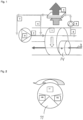
- Fig. 1 shows a schematic illustration of a sorption drying system according to the present invention.
- a mass 1 of absorbing or sorptive material is adapted to be flowed through by a moist gas stream 2 to be dehumidified.
- the absorbent mass 1 is adapted to rotate in the direction of the arrow, thereby being a rotor dryer.
- the absorbent mass 1 is part of a column dryer having a stationary absorbent mass 1 that is flowed through by a moist gas stream.
- the description will be directed to a rotary absorbent mass 1, a so-called drying wheel or rotor dryer.
- the corresponding features are, however, also applicable to a column dryer.
- the cooling may be carried out according to the same recirculating principle, but also by alternative cooling methods wherein the temperature rise of the absorbent mass is counteracted, for instance by a cooling coil in the absorbent mass or an air stream that passes the column or the tube without physical contact, similar to a cross flow heat exchanger with thermal contact.
- the absorbing material comprises silica gel, molecular sieves (also called mol sieves), zeolites, or a combination of the same.
- the absorption material is, however, not limited to these, but also other suitable absorbents are feasible.
- the sorptive material and its absorption capacity is adapted according to the change of the relative humidity of the moist gas stream in the direction of the gas stream through the absorbent mass 1. The temperature increases and the relative air humidity decreases with the distance from the inlet to the absorbent mass 1.
- the absorbent mass may comprise silica gel (SiO 2 ) near the inlet and mol sieve near the outlet.
- the moist gas stream 2 will be dehumidified by absorption, after which a dehumidified gas stream flows out of the absorbent mass on the other side.
- a stream of regeneration gas 3 is arranged to flow through the absorbent mass in the opposite direction of the moist gas stream. It is also within the scope of the invention that the stream of regeneration gas 3 flows through the absorbent mass 1 in the same the direction as the moist gas stream.
- the sorption drying system comprises a column dryer with stationary absorbent mass 1, the same is flowed through alternately by a moist gas stream for dehumidification and a stream of regeneration gas to drive out the moisture from the absorbent mass 1.
- the stream of regeneration gas 3 is heated by a heater 14 that may be placed in direct connection to the absorbent mass 1. It is also feasible that the heater 14 is situated further from the absorbent mass 1, or that the stream of regeneration gas 3 is heated in another way, for instance by the use of waste heat from a process wherein the sorption drying system is included.
- the absorbent mass 1 is formed as a rotor wherein channels or passages 10, 11 for the moist gas stream and the stream of regeneration gas 3 occupy different, separated circular sectors, which is illustrated in Fig. 2 .
- the channels 10, 11 are separated by means of radially arranged seals.
- the circular sectors 10, 11 do not define fixed channels in the disc of the absorbent mass 1, but the passage of the channels through the disc varies according to the rotation of the disc. Thus, the circular sectors 10, 11 delimit the instantaneous areas or zones of the flow of the gas streams 2, 3 into and out of the absorbent mass 1.
- the sorption drying system comprises means 4 for deflecting a part of the dehumidified gas stream that flows out of the absorbent mass 1.
- the means 4 may, for instance, comprise a fan or a pump 8, 9 that sucks in a part of the dehumidified gas stream into a separate conduit or channel 4 and leads it past a cooler 5.
- the cooler 5 may, for instance, comprise a heat exchanger, a heat pump, water-glycol batteries, a heat pipe, or a combination of the same.
- the deflected dehumidified gas stream is cooled by the cooler 5, whereupon the cooled dehumidified air is returned to the moist gas stream at its inlet into the absorbent mass 1 via a conduit 6, 7.
- a cooled recirculation flow is formed that efficiently cools the absorbent mass 1 without the supply of a separate cooling gas in a separate circular sector of the absorbent mass 1.
- Another advantage that is achieved is that the heat taken from the deflected dehumidified gas stream may be used to preheat the stream of regeneration gas 3.
- the fan 8, 9 that deflects a part of the dehumidified gas stream may, for instance, be situated between the outlet of the dehumidified gas stream from the rotary absorbent mass and the cooler 5, and/or between the cooler 5 and the inlet of the moist gas stream into the rotary absorbent mass.
- the cooled dehumidified air may advantageously be directed to the intake of the fan 9, so as to then be supplied to the inlet of the absorbent mass 1 for the moist gas stream 2. It is then possible to get along without the fan 8 depending on available pressures and desired flow in the deflected gas stream.
- the deflected dehumidified air is taken from an area or partial circular sector wherein the air is most moist. This is from a partial circular sector 10a essentially immediately after the circular sector of the stream of regeneration gas 3 in the direction of rotation of the disc, when the absorbent mass 1 is warm and possibly moist.
- the air is also deflected from a partial circular sector 10b essentially immediately before the circular sector of the stream of regeneration gas 3 in the direction of rotation of the disc, when the absorbent mass 1 is to a higher degree humidity-saturated than in the other areas of the disc. It is within the scope of the invention to combine deflection of a dehumidified gas stream from both the previously described partial circular sectors.
- the part of the dehumidified gas stream that is driest, i.e., from the partial circular sector 10 between the two above-mentioned partial circular sectors 10a, 10b, is allowed to proceed through the sorption drying system without deflection.
- the deflection sectors may be delimited and separated by means of rigid seals, but may also be made without rigid seals, the air being deflected in the vicinity of the two moist partial circular sectors 10a, 10b described above by a negative pressure formed by the fan 8, 9 in the conduit 4 that leads to the cooler 5.
- the heater power, the heater flow, the rotor speed, the cooled recirculation flow, and its cooling may be adapted based on the current dehumidification need. This can be made with knowledge about flows, inlet moist, and target moist of the dry air. A simpler variant of this is a temperature sensor at the inlet, when it is known that the air does not have higher air humidity than what the temperature allows, since the heater power of the dehumidifier, the heater flow, rotor speed, the cooled recirculation flow, and its cooling are controlled based on knowledge about its performance under different conditions. A temperature sensor is cheaper and more stable than a moist sensor.
- Another problem that arises in the sorption drying system is leakage between the moist gas stream and the stream of regeneration gas 3 since the seals that define and separate the channels of the gas streams are not absolutely tight. This leakage between the gas streams results in inferior dehumidification if the air from the regeneration flow for example leaks over to the dry air flow. Occasionally, the gas composition between the different flows may be in such a way that the leakage has to be controlled. Occasionally, the pressure ratios may in addition be variable because of connected equipment in channels and changed flows.
- a solution to this problem is to actively monitor and regulate the pressure of the stream of regeneration gas 3 and/or the moist gas stream 2 to counteract the leakage.
- the pressure of the gas streams is measured by means of suitable pressure transducers or gauges deployed in the flow of the respective gas stream through the sorption drying system.
- Fig. 3 shows a valve 12, arranged at or connecting to, for instance, the outlet of the stream of regeneration gas 3 from the absorbent mass that is adapted to regulate the pressure of the stream of regeneration gas 3 by adjusting the pressure drop through the valve 12. It is also within the scope of the present invention that the valve 12 is arranged at the inlet of the stream of regeneration gas 3 into the absorbent mass 1.
- the pressure of the stream of regeneration gas 3 is then regulated in such a way that it always is a little lower than the pressure of the moist gas stream.
- the valve 12 creates precisely so much pressure in the stream of regeneration gas 3 so that its pressure is essentially equal to the pressure of the moist gas stream, however always lower.
- leakage from the stream of regeneration gas 3 to the moist gas stream is prevented, at the same time as leakage in the opposite direction is minimized.
- the reason for a certain leakage being allowed from the moist gas stream to the stream of regeneration gas 3, but not vice versa, is that the air humidity of the dry air is not increased; alternatively that air from the regeneration side does not contaminate the dry air with its composition.
- the flow of the stream of regeneration gas 3 is affected. Therefore, the flow may need to be adjusted, for instance by means of a regulated fan 13.
- the part of the drying system that comprises the rotary absorbent mass 1 and its seals is built-in in an air-proof shell (not shown), inside which the leakage air builds up a pressure that makes the leakage to stop or be minimized.
- the leakage inside the shell passes further into the other air stream, it passes in a controlled way in the correct direction (as a consequence of the pressure control by the valve system). This construction eliminates losses out from the drying system.
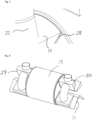
- Figs. 4-6 show in a perspective view a sorption drying system according to a first embodiment of the present invention. Reference designations of the corresponding features in Fig. 1 and Fig. 3 have been kept.
- the absorbent mass 1 in the form of a drying rotor is contained in a cylindrical housing 15.
- the housing 15 has an inlet side or inlet end portion 16 and an outlet side or outlet end portion 17.
- the gas stream 2 to be dehumidified or separated from another gas is directed into the drying rotor through a first, upper end portion connection 18 on the inlet side 16.
- the first end portion connection 18 is funnel-shaped and is shaped so that the gas stream 2 is directed inward toward an approximated circular sector-shaped area of the drying rotor.
- the inlet side 16 has also an outlet connection 20 for the stream of regeneration gas 3, which passes against the current through a regeneration sector 11 of the drying rotor. It is also feasible to allow the stream of regeneration gas 3 to pass the drying rotor with the current, whereupon the connection 20 then constitutes the inlet for the stream of regeneration gas 3.
- the dehumidified gas stream is received by the deflection means 4 in the form of a collection container 19.
- the collection container 19 covers a sector of the drying rotor that is essentially as large as, or preferably greater than, the sector that the moist gas stream 2 roughly is brought towards through the inlet connection 18, this in order to reliably capture essentially all dehumidified gas, but also to increase the amount of gas that is forwarded to the cooler 5.
- the amount of gas increases the cooling and decreases heating per passage through the drying rotor.
- the collection container 19 is placed so that the sector that is covered by the collection container 19 essentially corresponds to the inlet connection 18 for the moist gas stream. This to guarantee that deflection of the dehumidified gas stream takes place from an area on the outlet side 17 of the absorbent mass 1 that essentially corresponds to the area on the inlet side 16 of the absorbent mass 1 toward which the moist gas stream 2 is directed.
- the components that connect to the drying rotor on the inlet and/or the outlet side 16, 17 may be contained in a shell or housing (not shown). Leakage losses on the inlet and/or the outlet side 16, 17 will then build up a pressure inside the housing that counteracts further leakage. Furthermore, the housing contributes to the second end portion connection 25 for the cooled dehumidified gas stream not being strictly required, but the cooled dehumidified gas stream that is returned to the inlet side 16 is directed to the area of the drying rotor that is not embraced by the first end portion connection 18 for the moist gas stream and the sector 11 of the stream of regeneration gas 3. This is illustrated in Fig. 6 .
- Fig. 8 illustrates a second embodiment of a sorption drying system according to the present invention.
- the system comprises a collection container 29 that corresponds to the collection container 19.
- the collection container 29 comprises three essentially equally large sectors connected to the outlet side 17 of the drying rotor by means of seals 28 for receiving the dehumidified gas stream and directing it further to the cooler 5.
- the number of sectors is, however, not limited to three, but may be varied to achieve an optimal cooling of the drying rotor.
- the cooled, dehumidified gas stream is directed to the inlet side 16 of the drying rotor via a returning container 30.
- the returning container 30 comprises three sectors connected to the inlet side 16 of the drying rotor by means of seals 28, which are illustrated in Fig. 9 by the enlarged area of the returning container 30 in Fig. 8 .
- the three sectors of the returning container 30 are arranged in essentially the same positions on the inlet side 16 as the three sectors of the collection container 29 on the outlet side 17 so that the sectors are axially aligned with each other.
- the moist gas stream 2 is then directed through the remaining sectors of the drying rotor, separated from the sectors of the cooled, dehumidified gas stream.
- This configuration allows increased flow rate of the cooled, dehumidified gas stream for efficiently cooling down the drying rotor along its revolution, which gives an improved drying performance.
- Another conceivable solution is that the direction of flow of the cooled dehumidified gas stream is opposite the direction of flow of the moist gas stream through the absorbent mass 1. This can be achieved by means of, for instance, fans.
Landscapes
- Engineering & Computer Science (AREA)
- Chemical & Material Sciences (AREA)
- Combustion & Propulsion (AREA)
- Mechanical Engineering (AREA)
- General Engineering & Computer Science (AREA)
- Analytical Chemistry (AREA)
- General Chemical & Material Sciences (AREA)
- Oil, Petroleum & Natural Gas (AREA)
- Chemical Kinetics & Catalysis (AREA)
- Drying Of Gases (AREA)
Description
- The present invention concerns a sorption drying system for dehumidification of a moist gas stream comprising a mass of absorbing material, a moist gas stream arranged to flow through at least a part of the absorbent mass, and a heated stream of regeneration gas arranged to flow through at least a part of the absorbent mass. In a second aspect, the present invention concerns a method for dehumidification of a moist gas stream in such a sorption drying system comprising a mass of absorbing material.
- Systems for dehumidification or drying of moist gas streams are known since long. Examples of such systems are found in, among others,
US 4,701,189 andUS 2005/0235827 , which disclose rotary drying wheels. The drying wheel contains a mass of absorbing or sorptive material (drying agent) that removes moisture from the gas stream by the vapour being absorbed. The moisture is picked up in the drying agent and the dry gas stream is forwarded for the use in a process or the like. After a prolonged dehumidification, the drying agent will be saturated with moisture, and therefore it is required that the moisture has to be driven out of the drying agent for enabling the drying to proceed. This is usually made by regeneration, i.e., that a heated gas stream passes through the drying wheel in an area separated from the passage of the moist gas stream. The heated air regenerates the drying wheel continuously, which thereby gives a continuous drying of the moist gas stream. - A problem of such drying wheels is that, upon absorption of vapour, latent heat in the gas stream is converted into sensible heat, i.e., the evaporation energy in absorption increases the temperature of the gas and drying agent, which impairs its absorption capacity. Likewise, also the regeneration increases the temperature of the drying wheel.
-
US 2011/0132191 andUS 2012/0125198 disclose proposals of solutions wherein a separate gas stream for the cooling of the absorbing drying agent flows through the drying wheel in a delimited zone or sector separated from the main flow of the gas to be dried and the regeneration flow. Disadvantages of these solutions are that they require an additional flow for the cooling gas with associated equipment and that the available sector for the drying of the gas in the main flow is reduced, which impairs the capacity of the drying wheel. Another disadvantage is that the cooling sector only cools the drying agent in the beginning of its revolution; during the remaining part of the revolution, the drying agent is heated during the absorption. -
JP 60-102919 -
- The object of the present invention is to provide systems and methods for improving the performance of sorption dryers.
- This is achieved by a sorption drying system for dehumidification of a moist gas stream according to claim 1, comprising a mass of absorbing material in the form of a drying rotor that is adapted to rotate about a central axis, a moist gas stream arranged to flow through at least a part of a first circular sector comprising a first partial circular sector, a second partial circular sector and a third partial circular sector of the drying rotor, the third partial sector being arranged in between the first partial sector and the second partial sector, and a heated stream of regeneration gas arranged to flow through a second circular sector separated from the first circular sector by means of seals, the drying rotor. The sorption drying system further comprises means for deflecting a part of the dehumidified gas stream after flowing through the drying rotor, from the first partial sector located immediately after the second sector and from the second partial sector located immediately before the second sector as seen in the direction of rotation of the drying rotor, a cooler for cooling the deflected dehumidified gas stream, and means for returning the cooled deflected dehumidified gas stream to the inlet into the drying rotor. The deflected dehumidified gas stream that has passed the third partial sector arranged in between the first partial sector and the second partial sector is allowed to pass through the sorption drying system without deflection and whereby at least a part of the cooled deflected dehumidified gas stream is arranged to flow through the drying rotor separated from the moist gas stream.
- By reusing a part of the already dehumidified gas stream that has been cooled to lower the temperature in the drying rotor, a lower, more optimal temperature for dehumidification is attained, where the drying rotor more efficiently absorbs the moisture in the gas stream. Simultaneously, the advantage is achieved that the supplied cooled gas stream contributes with less additional moisture, since it is already partly dehumidified. If the balance between cooled deflected dehumidified gas and moist gas is optimized, the drying performance is increased in spite of the fact that flow rates of the gas(-es) through the drying rotor may differ and/or be elevated. By separating at least a part of the cooled deflected dehumidified gas stream from the moist gas stream, a controlled recirculation or return of the cooled deflected dehumidified gas stream is achieved. This means that the flow rate or the air flow of the cooled dehumidified gas stream can be increased so that it efficiently cools down the drying rotor.
- In another embodiment, deflection of the dehumidified gas stream occurs from an area on the outlet side of the drying rotor that essentially corresponds to the area on the inlet side of the drying rotor toward which the moist gas stream is directed. This means that the dehumidified gas stream is deflected from an area of the drying rotor that is humidity-saturated to a higher degree than the other areas, which impairs its absorption capacity. Then the part of the dehumidified gas stream that is allowed to pass without deflection comes from areas of lower degree of saturation, and thereby better absorption capacity, which gives an improved drying performance of the sorption drying system.
- At least a part of the cooled dehumidified gas stream flows through the drying rotor in a channel separated from the moist gas stream by means of seals.
- In a preferred embodiment, the means for deflection comprises a fan situated between the outlet of the dehumidified gas stream from the drying rotor and the cooler.
- In an alternative embodiment, the means for deflection comprises a fan situated between the cooler and the inlet of the moist gas stream into the drying rotor.
- The absorbent mass is in the form of a rotor and is adapted to rotate about a central axis, the moist gas stream being adapted to flow through a first channel of the rotor and the stream of regeneration gas being adapted to flow through a second channel of the rotor, separated from the first channel by means of seals, and the channels essentially having the shape of circular sectors.
- Further, the deflection of the dehumidified gas stream occurs in a partial circular sector situated essentially immediately after the circular sector of the stream of regeneration gas in the direction of rotation of the absorbent rotor. The deflection of the dehumidified gas stream also occurs in a partial circular sector situated essentially immediately before the circular sector of the stream of regeneration gas in the direction of rotation of the absorbent disc.
- In another embodiment, the sorption drying system comprises a valve situated at the outlet or outlet from the drying rotor of the stream of regeneration gas for regulating the pressure of the stream of regeneration gas.
- In a preferred embodiment, the sorption drying system comprises a fan for varying the flow of the stream of regeneration gas through the drying rotor.
- In an alternative embodiment, the parts of the drying system that comprise the absorbent mass and its seals are built-in in an air-proof housing.
- In a second aspect, the present invention concerns a method for dehumidification of a gas stream in a sorption drying system comprising a mass of absorbing material in the form of a drying rotor that is adapted to rotate about a central axis, wherein the method comprises the steps of:
- directing a moist gas stream through a first circular sector comprising a first partial circular sector a second partial circular sector and a third partial circular sector of the drying rotor, the third partial sector being arranged in between the first partial sector and the second partial sector,
- directing a heated stream of regeneration gas through a second circular sector separated from the first circular sector by means of seals, in the drying rotor; and
- deflecting a part of the dehumidified gas stream after flowing through drying rotor from the first partial sector located immediately after the second sector and from the second partial sector located immediately before the second sector as seen in the direction of rotation of the drying rotor;
- cooling the deflected dehumidified gas stream; and
- returning the cooled deflected dehumidified gas stream to the moist gas stream at the inlet into the drying rotor, whereby a part of the dehumidified gas stream that has passed the third partial sector arranged in between the first partial sector and the second partial sector is allowed to pass through the sorption drying system without deflection and whereby the method further comprises the step of:
directing at least a part of the cooled deflected dehumidified gas stream through the drying rotor separated from the moist gas stream. - Preferred embodiments of the method comprise features corresponding to the features of the sorption drying system.
- In a preferred embodiment, the method comprises the step of regulating the pressure of the stream of regeneration gas in such a way that this is essentially equal to, however always lower than, the pressure of the moist gas stream.
-
-
Fig. 1 shows in a schematic view a sorption drying system having a cooled recirculation flow according to the present invention; -
Fig. 2 shows in a schematic view an absorbent disc according to the present invention; -
Fig. 3 shows in a schematic view a sorption drying system with regulated gas stream pressure according to the present invention; -
Fig. 4 shows in a perspective view a sorption drying system having a cooler according to a first embodiment of the present invention; -
Fig. 5 shows in a perspective view a sorption drying system according to a first embodiment of the present invention; -
Fig. 6 shows in a perspective view a sorption drying system according to a first embodiment of the present invention; -
Fig. 7 shows a detail of the sorption drying system inFig. 4 ; -
Fig. 8 shows in a perspective view a sorption drying system according to a second embodiment of the present invention; and -
Fig. 9 shows a detail of the sorption drying system inFig. 8 . - Below, the sorption drying system will be described more in detail, reference being made to the figures. However, the invention should not be considered limited to the embodiment or embodiments shown in the figures and described below, but may be varied within the scope of the claims.
- The concepts "drying" and "dehumidification" may be interpreted in a strict way as a process to remove water from an air stream or gas stream. In the present description, however, the concepts should be interpreted in a wider meaning to remove or separate an absorbable and/or condensable component from an air stream or gas stream. Examples of such components that fall within the scope of the present invention are volatile organic compounds (VOCs), carbon dioxide, and/or carbon monoxide. The invention is, however, not limited to these.
-
Fig. 1 shows a schematic illustration of a sorption drying system according to the present invention. A mass 1 of absorbing or sorptive material is adapted to be flowed through by amoist gas stream 2 to be dehumidified. Preferably, the absorbent mass 1 is adapted to rotate in the direction of the arrow, thereby being a rotor dryer. In an alternative embodiment which is not part of the invention, the absorbent mass 1 is part of a column dryer having a stationary absorbent mass 1 that is flowed through by a moist gas stream. In the following, the description will be directed to a rotary absorbent mass 1, a so-called drying wheel or rotor dryer. The corresponding features are, however, also applicable to a column dryer. The cooling may be carried out according to the same recirculating principle, but also by alternative cooling methods wherein the temperature rise of the absorbent mass is counteracted, for instance by a cooling coil in the absorbent mass or an air stream that passes the column or the tube without physical contact, similar to a cross flow heat exchanger with thermal contact. - The absorbing material comprises silica gel, molecular sieves (also called mol sieves), zeolites, or a combination of the same. The absorption material is, however, not limited to these, but also other suitable absorbents are feasible. In a preferred embodiment, the sorptive material and its absorption capacity is adapted according to the change of the relative humidity of the moist gas stream in the direction of the gas stream through the absorbent mass 1. The temperature increases and the relative air humidity decreases with the distance from the inlet to the absorbent mass 1. For instance, the absorbent mass may comprise silica gel (SiO2) near the inlet and mol sieve near the outlet.
- During the throughflow of the absorbent mass 1, the
moist gas stream 2 will be dehumidified by absorption, after which a dehumidified gas stream flows out of the absorbent mass on the other side. - For the regeneration of the absorbent mass 1, i.e., drive out the moisture from the absorbent mass, a stream of
regeneration gas 3 is arranged to flow through the absorbent mass in the opposite direction of the moist gas stream. It is also within the scope of the invention that the stream ofregeneration gas 3 flows through the absorbent mass 1 in the same the direction as the moist gas stream. In case the sorption drying system comprises a column dryer with stationary absorbent mass 1, the same is flowed through alternately by a moist gas stream for dehumidification and a stream of regeneration gas to drive out the moisture from the absorbent mass 1. - The stream of
regeneration gas 3 is heated by aheater 14 that may be placed in direct connection to the absorbent mass 1. It is also feasible that theheater 14 is situated further from the absorbent mass 1, or that the stream ofregeneration gas 3 is heated in another way, for instance by the use of waste heat from a process wherein the sorption drying system is included. - The absorbent mass 1 is formed as a rotor wherein channels or
passages regeneration gas 3 occupy different, separated circular sectors, which is illustrated inFig. 2 . Thechannels circular sectors circular sectors gas streams - In order to counteract the impaired absorption capacity of the absorbent mass 1 due to heating as a consequence of moisture absorption, and in order to increase the number of passages through the absorbent mass 1, the sorption drying system comprises means 4 for deflecting a part of the dehumidified gas stream that flows out of the absorbent mass 1. The
means 4 may, for instance, comprise a fan or apump 8, 9 that sucks in a part of the dehumidified gas stream into a separate conduit orchannel 4 and leads it past acooler 5. Thecooler 5 may, for instance, comprise a heat exchanger, a heat pump, water-glycol batteries, a heat pipe, or a combination of the same. The deflected dehumidified gas stream is cooled by thecooler 5, whereupon the cooled dehumidified air is returned to the moist gas stream at its inlet into the absorbent mass 1 via aconduit - Another advantage that is achieved is that the heat taken from the deflected dehumidified gas stream may be used to preheat the stream of
regeneration gas 3. - The
fan 8, 9 that deflects a part of the dehumidified gas stream may, for instance, be situated between the outlet of the dehumidified gas stream from the rotary absorbent mass and thecooler 5, and/or between thecooler 5 and the inlet of the moist gas stream into the rotary absorbent mass. In the latter case, the cooled dehumidified air may advantageously be directed to the intake of thefan 9, so as to then be supplied to the inlet of the absorbent mass 1 for themoist gas stream 2. It is then possible to get along without the fan 8 depending on available pressures and desired flow in the deflected gas stream. - The deflected dehumidified air is taken from an area or partial circular sector wherein the air is most moist. This is from a partial
circular sector 10a essentially immediately after the circular sector of the stream ofregeneration gas 3 in the direction of rotation of the disc, when the absorbent mass 1 is warm and possibly moist. The air is also deflected from a partialcircular sector 10b essentially immediately before the circular sector of the stream ofregeneration gas 3 in the direction of rotation of the disc, when the absorbent mass 1 is to a higher degree humidity-saturated than in the other areas of the disc. It is within the scope of the invention to combine deflection of a dehumidified gas stream from both the previously described partial circular sectors. The part of the dehumidified gas stream that is driest, i.e., from the partialcircular sector 10 between the two above-mentioned partialcircular sectors - The deflection sectors may be delimited and separated by means of rigid seals, but may also be made without rigid seals, the air being deflected in the vicinity of the two moist partial
circular sectors fan 8, 9 in theconduit 4 that leads to thecooler 5. - For reducing the energy consumption of the sorption drying system, the heater power, the heater flow, the rotor speed, the cooled recirculation flow, and its cooling may be adapted based on the current dehumidification need. This can be made with knowledge about flows, inlet moist, and target moist of the dry air. A simpler variant of this is a temperature sensor at the inlet, when it is known that the air does not have higher air humidity than what the temperature allows, since the heater power of the dehumidifier, the heater flow, rotor speed, the cooled recirculation flow, and its cooling are controlled based on knowledge about its performance under different conditions. A temperature sensor is cheaper and more stable than a moist sensor.
- Another problem that arises in the sorption drying system is leakage between the moist gas stream and the stream of
regeneration gas 3 since the seals that define and separate the channels of the gas streams are not absolutely tight. This leakage between the gas streams results in inferior dehumidification if the air from the regeneration flow for example leaks over to the dry air flow. Occasionally, the gas composition between the different flows may be in such a way that the leakage has to be controlled. Occasionally, the pressure ratios may in addition be variable because of connected equipment in channels and changed flows. - A solution to this problem is to actively monitor and regulate the pressure of the stream of
regeneration gas 3 and/or themoist gas stream 2 to counteract the leakage. The pressure of the gas streams is measured by means of suitable pressure transducers or gauges deployed in the flow of the respective gas stream through the sorption drying system.Fig. 3 shows avalve 12, arranged at or connecting to, for instance, the outlet of the stream ofregeneration gas 3 from the absorbent mass that is adapted to regulate the pressure of the stream ofregeneration gas 3 by adjusting the pressure drop through thevalve 12. It is also within the scope of the present invention that thevalve 12 is arranged at the inlet of the stream ofregeneration gas 3 into the absorbent mass 1. The pressure of the stream ofregeneration gas 3 is then regulated in such a way that it always is a little lower than the pressure of the moist gas stream. In other words, thevalve 12 creates precisely so much pressure in the stream ofregeneration gas 3 so that its pressure is essentially equal to the pressure of the moist gas stream, however always lower. Thereby, leakage from the stream ofregeneration gas 3 to the moist gas stream is prevented, at the same time as leakage in the opposite direction is minimized. The reason for a certain leakage being allowed from the moist gas stream to the stream ofregeneration gas 3, but not vice versa, is that the air humidity of the dry air is not increased; alternatively that air from the regeneration side does not contaminate the dry air with its composition. - Because of the activity of the
valve 12, the flow of the stream ofregeneration gas 3 is affected. Therefore, the flow may need to be adjusted, for instance by means of aregulated fan 13. - Another further problem that may arise is that a required rise of the pressures in the gas streams causes leakage through the peripheral seals of the sorption drying system. In a preferred embodiment, the part of the drying system that comprises the rotary absorbent mass 1 and its seals is built-in in an air-proof shell (not shown), inside which the leakage air builds up a pressure that makes the leakage to stop or be minimized. Moreover, should the occasion arise, when the leakage inside the shell passes further into the other air stream, it passes in a controlled way in the correct direction (as a consequence of the pressure control by the valve system). This construction eliminates losses out from the drying system.
-
Figs. 4-6 show in a perspective view a sorption drying system according to a first embodiment of the present invention. Reference designations of the corresponding features inFig. 1 andFig. 3 have been kept. Here, the absorbent mass 1 in the form of a drying rotor is contained in acylindrical housing 15. Thehousing 15 has an inlet side orinlet end portion 16 and an outlet side oroutlet end portion 17. Thegas stream 2 to be dehumidified or separated from another gas is directed into the drying rotor through a first, upperend portion connection 18 on theinlet side 16. The firstend portion connection 18 is funnel-shaped and is shaped so that thegas stream 2 is directed inward toward an approximated circular sector-shaped area of the drying rotor. Theinlet side 16 has also anoutlet connection 20 for the stream ofregeneration gas 3, which passes against the current through aregeneration sector 11 of the drying rotor. It is also feasible to allow the stream ofregeneration gas 3 to pass the drying rotor with the current, whereupon theconnection 20 then constitutes the inlet for the stream ofregeneration gas 3. - The drying rotor rotates clockwise as seen from the
inlet side 16. The moist air in thegas stream 2 is then roughly brought into a part of the drying rotor that is about to enter theregeneration sector 11. In this application of controlled recirculation, this has the advantage that the moist air is pre-dried, since a large concentration difference between themoist gas stream 2 and the drying rotor is utilized by using a more saturated part of the drying rotor. - On the
outlet side 17, the dehumidified gas stream is received by the deflection means 4 in the form of acollection container 19. Thecollection container 19 covers a sector of the drying rotor that is essentially as large as, or preferably greater than, the sector that themoist gas stream 2 roughly is brought towards through theinlet connection 18, this in order to reliably capture essentially all dehumidified gas, but also to increase the amount of gas that is forwarded to thecooler 5. The amount of gas increases the cooling and decreases heating per passage through the drying rotor. Thecollection container 19 is placed so that the sector that is covered by thecollection container 19 essentially corresponds to theinlet connection 18 for the moist gas stream. This to guarantee that deflection of the dehumidified gas stream takes place from an area on theoutlet side 17 of the absorbent mass 1 that essentially corresponds to the area on theinlet side 16 of the absorbent mass 1 toward which themoist gas stream 2 is directed. - The
collection container 19 may also have asecond collection sector 21 arranged immediately after theregeneration sector 11, where the drying rotor is warm and thereby dries poorly and may also after steam. Theoutlet side 17 has also aninlet 23 for the stream ofregeneration gas 3 in case a counter-current regeneration is used, and vice versa for a concurrent regeneration. - The dehumidified gas that is collected in the
collection container 19 is sucked into thecooler 5 through thetube 22 by means of, for instance, a fan (not shown) that has been described above. The dehumidified gas is cooled and reintroduced on theinlet side 16 of the drying rotor bymeans 6 in the form of atube 24 and a secondend portion connection 25 for the cooled, dehumidified gas stream, which is separated from the firstend portion connection 18 for themoist gas stream 2. As indicated above, also a part of the cooled, dehumidified gas stream may be mixed with themoist gas stream 2 via means 7 (not shown), for instance by connecting a conduit or tube from thecooler 5 or thetube 24 to theinlet connection 18. Alternatively, the cooled dehumidified gas stream may partly mingle with the moist gas stream in connection with natural pressure equalizing. - The sectors where the first and second, respectively,
end portion connection inlet side 16 can be separated by means ofseals 28, for instance thin rubber mouldings or squeegees;Fig. 7 shows an enlarged area of thecollection container 19 inFig. 4 at its connection to the drying rotor whereseal 28 is illustrated. Theseals 28 are, however, not necessary for separating the cooled, dehumidified gas stream from themoist gas stream 2, since the moist gas stream is directed toward its sector and is sucked through the drying rotor by means of a fan (not shown). Another advantage of not using seals is that unbalances that arise as a consequence of pressure differences between the cooled, dehumidified gas stream and themoist gas stream 2 are levelled out. In order to further improve the pressure equalizing,gaps end portion connection end portion connection - As mentioned above, the components that connect to the drying rotor on the inlet and/or the
outlet side outlet side end portion connection 25 for the cooled dehumidified gas stream not being strictly required, but the cooled dehumidified gas stream that is returned to theinlet side 16 is directed to the area of the drying rotor that is not embraced by the firstend portion connection 18 for the moist gas stream and thesector 11 of the stream ofregeneration gas 3. This is illustrated inFig. 6 . -
Fig. 8 illustrates a second embodiment of a sorption drying system according to the present invention. Here, the system comprises acollection container 29 that corresponds to thecollection container 19. The difference is that thecollection container 29 comprises three essentially equally large sectors connected to theoutlet side 17 of the drying rotor by means ofseals 28 for receiving the dehumidified gas stream and directing it further to thecooler 5. The number of sectors is, however, not limited to three, but may be varied to achieve an optimal cooling of the drying rotor. After cooling, the cooled, dehumidified gas stream is directed to theinlet side 16 of the drying rotor via a returningcontainer 30. Also the returningcontainer 30 comprises three sectors connected to theinlet side 16 of the drying rotor by means ofseals 28, which are illustrated inFig. 9 by the enlarged area of the returningcontainer 30 inFig. 8 . - The three sectors of the returning
container 30 are arranged in essentially the same positions on theinlet side 16 as the three sectors of thecollection container 29 on theoutlet side 17 so that the sectors are axially aligned with each other. Themoist gas stream 2 is then directed through the remaining sectors of the drying rotor, separated from the sectors of the cooled, dehumidified gas stream. This configuration allows increased flow rate of the cooled, dehumidified gas stream for efficiently cooling down the drying rotor along its revolution, which gives an improved drying performance. Another conceivable solution is that the direction of flow of the cooled dehumidified gas stream is opposite the direction of flow of the moist gas stream through the absorbent mass 1. This can be achieved by means of, for instance, fans. - The invention is of course not limited to the embodiments that are illustrated here, but may be varied within the scope of protection that is defined by the claims.
Claims (12)
- Sorption drying system for dehumidification of a moist gas stream, comprising:- a mass (1) of absorbing material in the form of a drying rotor that is adapted to rotate about a central axis;- a moist gas stream (2) arranged to flow through at least a part of a first circular sector comprising a first partial circular sector (10a), a second partial circular sector (10b) and a third partial circular sector (10) of the drying rotor (1), the third partial sector (10) being arranged in between the first partial sector (10a) and the second partial sector (10b);- a heated stream of regeneration gas (3) arranged to flow through a second circular sector (11), separated from the first circular sector by means of seals, through the drying rotor (1),- means (4, 19, 21, 22) for deflecting a part of the dehumidified gas stream after flowing through the drying rotor (1) from the first partial sector (10a) located immediately after the second sector (11) and from the second partial sector (10b) located immediately before the second sector (11) as seen in the direction of rotation of the drying rotor (1);- a cooler (5) for cooling the deflected dehumidified gas stream; and- means (6, 24, 25, 7) for returning the cooled deflected dehumidified gas stream to the inlet into the drying rotor (1),wherein the dehumidified gas stream that has passed the third partial sector (10) arranged in between the first partial sector (10a) and the second partial sector (10b) is allowed to pass through the sorption drying system without deflection;and wherein at least a part of the cooled deflected dehumidified gas stream is arranged to flow through the drying rotor (1) separated from the moist gas stream (2).
- Sorption drying system according to claim 1, wherein deflection of the dehumidified gas stream takes place from an area on an outlet side (17) of the drying rotor (1) that essentially corresponds to the area on the inlet side (16) of the drying rotor (1) toward which the moist gas stream (2) is directed.
- Sorption drying system according to claim 1, wherein the cooled dehumidified gas stream flows through the drying rotor (1) in a sector separated from the moist gas stream (2) by means of seals (28).
- Sorption drying system according to any one of the preceding claims, wherein the means for deflection comprises a fan (8) situated between the outlet of the dehumidified gas stream from the drying rotor (1) and the cooler (5).
- Sorption drying system according to any one of the preceding claims, wherein the means for deflection comprises a fan (9) situated between the cooler (5) and the inlet of the moist gas stream (2) into the drying rotor (1).
- Sorption drying system according to any one of the preceding claims, further comprising a valve (12) situated at the inlet into or outlet from the drying rotor (1) of the stream of regeneration gas (3) for regulating the pressure of the stream of regeneration gas (3).
- Sorption drying system according to claim 6, further comprising a fan (13) for varying the flow of the stream of regeneration gas (3) through the drying rotor (1).
- Sorption drying system according to any one of the preceding claims, further comprising a valve situated at the inlet into or outlet from the drying rotor (1) of the moist gas stream (2) for regulating the pressure of the moist gas stream (2).
- Sorption drying system according to claim 1, further comprising a fan (9) for varying the flow of the moist gas stream (2) through the absorbent mass (1).
- Sorption drying system according to any one of the preceding claims, wherein the parts of the drying system that comprise the absorbent mass (1) and its seals (28) are built-in in an air-proof housing.
- Method for dehumidification of a gas stream (2) in a sorption drying system comprising a mass (1) of absorbing material in the form of a drying rotor that is adapted to rotate about a central axis, wherein the method comprises the steps of:- directing a moist gas stream (2) through a first circular sector comprising a first partial circular sector (10a), a second partial circular sector (10b) and a third partial circular sector (10) of the drying rotor (1), the third partial sector (10) being arranged in between the first partial sector (10a) and the second partial sector (10b)- directing a heated stream of regeneration gas (3) through a second circular sector (11), separated from the first circular sector by means of seals, in the drying rotor (1);- deflecting the dehumidified gas stream after flowing through the drying rotor (1) from the first partial sector (10a) located immediately after the second sector (11) and from the second partial sector (10b) located immediately before the second sector (11) as seen in the direction of rotation of the drying rotor (1);- cooling the deflected dehumidified gas stream; and- returning the cooled deflected dehumidified gas stream at the inlet into the drying rotor (1), wherein a part of the dehumidified gas stream that has passed the third partial sector (10) arranged in between the first partial sector (10a) and the second partial sector (10b) is allowed to pass through the sorption drying system without deflection and wherein the method further comprises the step of:- directing at least a part of the cooled deflected dehumidified gas stream through the drying rotor (1) separated from the moist gas stream (2).
- Method according to claim 11, further comprising the step of regulating the pressure of the stream of regeneration gas (3) and/or the moist gas stream (2) in such a way that the pressure of the stream of regeneration gas (3) is essentially equal to, however always lower than, the pressure of the moist gas stream (2).
Applications Claiming Priority (2)
| Application Number | Priority Date | Filing Date | Title |
|---|---|---|---|
| SE1250744A SE537905C2 (en) | 2012-06-29 | 2012-06-29 | Sorption drying system and method for dehumidifying a moist gas stream |
| PCT/SE2013/050843 WO2014003683A1 (en) | 2012-06-29 | 2013-07-01 | A sorption drying system |
Publications (3)
| Publication Number | Publication Date |
|---|---|
| EP2866920A1 EP2866920A1 (en) | 2015-05-06 |
| EP2866920B1 true EP2866920B1 (en) | 2025-01-01 |
| EP2866920C0 EP2866920C0 (en) | 2025-01-01 |
Family
ID=49301588
Family Applications (1)
| Application Number | Title | Priority Date | Filing Date |
|---|---|---|---|
| EP13771644.5A Active EP2866920B1 (en) | 2012-06-29 | 2013-07-01 | A sorption drying system |
Country Status (4)
| Country | Link |
|---|---|
| US (1) | US9616380B2 (en) |
| EP (1) | EP2866920B1 (en) |
| SE (1) | SE537905C2 (en) |
| WO (1) | WO2014003683A1 (en) |
Families Citing this family (6)
| Publication number | Priority date | Publication date | Assignee | Title |
|---|---|---|---|---|
| US10232306B2 (en) * | 2012-06-29 | 2019-03-19 | Ctt Systems Ab | Sorption drying system |
| JP6376890B2 (en) * | 2014-08-13 | 2018-08-22 | クボタ空調株式会社 | Desiccant block device and desiccant air conditioner |
| DE102015201342A1 (en) * | 2015-01-27 | 2016-07-28 | Airbus Operations Gmbh | A cabin air extraction system, method of operating a cabin air extraction system, and aircraft air conditioning system |
| JP6528097B2 (en) * | 2015-05-29 | 2019-06-12 | シャープ株式会社 | Dehumidifying device and dehumidifying method |
| CN114887454A (en) * | 2022-06-09 | 2022-08-12 | 广州捷达莱堡通用设备有限公司 | Self-purifying rotary wheel type filtering device |
| CN117123036B (en) * | 2023-08-31 | 2024-08-30 | 国网湖北省电力有限公司荆州供电公司 | Transformer moisture absorption device for distribution transformer |
Citations (2)
| Publication number | Priority date | Publication date | Assignee | Title |
|---|---|---|---|---|
| WO2011017785A1 (en) * | 2009-08-11 | 2011-02-17 | Atlas Copco Airpower | Method and device for drying of a gas |
| WO2011017784A1 (en) * | 2009-08-11 | 2011-02-17 | Atlas Copco Airpower | Compressor installation with a dryer and method for drying of compressed gasses |
Family Cites Families (14)
| Publication number | Priority date | Publication date | Assignee | Title |
|---|---|---|---|---|
| US4701189A (en) | 1980-07-07 | 1987-10-20 | Near Equilibrium Research Associates | Rotary sorption bed system and method of use |
| JPS5726331A (en) * | 1980-07-24 | 1982-02-12 | Toyobo Co Ltd | Air cooling system and air conditioning system using activated carbon fiber |
| JPS60102919A (en) | 1983-11-10 | 1985-06-07 | Toyobo Co Ltd | Dehumidification of high humidity air |
| US5242473A (en) * | 1988-09-22 | 1993-09-07 | Unico Kogyo Kabushiki Kaisha | Apparatus for dehumidifying gas |
| US5512083A (en) * | 1993-10-25 | 1996-04-30 | Uop | Process and apparatus for dehumidification and VOC odor remediation |
| JPH09173758A (en) * | 1995-12-21 | 1997-07-08 | Toho Kako Kensetsu Kk | High boiling point solvent recovery device |
| US5891219A (en) * | 1998-01-13 | 1999-04-06 | Durr Environmental, Inc. | Two stage rotary concentrator |
| AU5466400A (en) * | 1999-06-04 | 2000-12-28 | Flair Corporation | Rotating drum adsorber process and system |
| KR20050057144A (en) * | 2002-09-20 | 2005-06-16 | 동경 엘렉트론 주식회사 | Dry air-supplying apparatus and treating apparatus |
| US7166149B2 (en) | 2004-01-12 | 2007-01-23 | Uop Llc | Adsorption process for continuous purification of high value gas feeds |
| US20050217481A1 (en) * | 2004-03-31 | 2005-10-06 | Dunne Stephen R | Rotary adsorbent contactors for drying, purification and separation of gases |
| US7101414B2 (en) | 2004-04-27 | 2006-09-05 | Munters Corporation | Rotary bed sorption system including at least one recycled isolation loop, and methods of designing and operating such a system |
| WO2010134284A1 (en) * | 2009-05-22 | 2010-11-25 | ダイキン工業株式会社 | Method for treating fluid, apparatus for treating fluid, and fluid |
| EP2332631B1 (en) | 2009-12-03 | 2012-11-14 | Kaeser Kompressoren GmbH | Absorption drying device and absorption drying method |
-
2012
- 2012-06-29 SE SE1250744A patent/SE537905C2/en unknown
-
2013
- 2013-07-01 US US14/411,639 patent/US9616380B2/en active Active
- 2013-07-01 WO PCT/SE2013/050843 patent/WO2014003683A1/en not_active Ceased
- 2013-07-01 EP EP13771644.5A patent/EP2866920B1/en active Active
Patent Citations (2)
| Publication number | Priority date | Publication date | Assignee | Title |
|---|---|---|---|---|
| WO2011017785A1 (en) * | 2009-08-11 | 2011-02-17 | Atlas Copco Airpower | Method and device for drying of a gas |
| WO2011017784A1 (en) * | 2009-08-11 | 2011-02-17 | Atlas Copco Airpower | Compressor installation with a dryer and method for drying of compressed gasses |
Also Published As
| Publication number | Publication date |
|---|---|
| EP2866920A1 (en) | 2015-05-06 |
| SE1250744A1 (en) | 2013-12-30 |
| SE537905C2 (en) | 2015-11-17 |
| EP2866920C0 (en) | 2025-01-01 |
| US9616380B2 (en) | 2017-04-11 |
| US20150165371A1 (en) | 2015-06-18 |
| WO2014003683A1 (en) | 2014-01-03 |
Similar Documents
| Publication | Publication Date | Title |
|---|---|---|
| US9616380B2 (en) | Sorption drying system | |
| KR101473537B1 (en) | Method and device for drying of a gas | |
| DK3046656T3 (en) | Compressor system equipped with a dryer and method for drying gas | |
| JPH08238414A (en) | Method and apparatus for drying moist gas | |
| JP5686311B2 (en) | Gas removal system | |
| JP2005185930A (en) | Dehumidifier | |
| KR20170120565A (en) | Dryer for compressed gas, compressor installation provided with such a dryer and method for drying gas | |
| US10232306B2 (en) | Sorption drying system | |
| JP3581137B2 (en) | Dehumidifier | |
| CA3240151A1 (en) | Rotary bed dehumidification system and method with control of condensation in recirculating loop | |
| CN105202877A (en) | Multibarrel-molecular-sieve-rotating-wheel intermittent-cycle-type dehumidifying dryer | |
| JP4455363B2 (en) | Dehumidifying / humidifying device and ventilation system | |
| JP2005262068A (en) | Dehumidifier | |
| JP6793430B2 (en) | Dehumidifier | |
| US20240375044A1 (en) | A desiccant dehumidifier | |
| CN205860280U (en) | Air conditioner and fresh air exchange system thereof | |
| JP5570717B2 (en) | Operation method of dry dehumidifier | |
| JP6663655B2 (en) | Desiccant air conditioner | |
| JP6231418B2 (en) | Cooling dehumidification system | |
| KR101362663B1 (en) | Dehumidifying apparatus | |
| JP2007185657A (en) | Dehumidifier | |
| JP6235392B2 (en) | Air conditioner | |
| CN219934144U (en) | Air duct structure of rotary dehumidifier | |
| JP2014035135A (en) | Humidity controller | |
| JP2002177729A (en) | Humidifier |
Legal Events
| Date | Code | Title | Description |
|---|---|---|---|
| PUAI | Public reference made under article 153(3) epc to a published international application that has entered the european phase |
Free format text: ORIGINAL CODE: 0009012 |
|
| 17P | Request for examination filed |
Effective date: 20150129 |
|
| AK | Designated contracting states |
Kind code of ref document: A1 Designated state(s): AL AT BE BG CH CY CZ DE DK EE ES FI FR GB GR HR HU IE IS IT LI LT LU LV MC MK MT NL NO PL PT RO RS SE SI SK SM TR |
|
| AX | Request for extension of the european patent |
Extension state: BA ME |
|
| DAX | Request for extension of the european patent (deleted) | ||
| STAA | Information on the status of an ep patent application or granted ep patent |
Free format text: STATUS: EXAMINATION IS IN PROGRESS |
|
| 17Q | First examination report despatched |
Effective date: 20191108 |
|
| GRAP | Despatch of communication of intention to grant a patent |
Free format text: ORIGINAL CODE: EPIDOSNIGR1 |
|
| STAA | Information on the status of an ep patent application or granted ep patent |
Free format text: STATUS: GRANT OF PATENT IS INTENDED |
|
| INTG | Intention to grant announced |
Effective date: 20240829 |
|
| GRAS | Grant fee paid |
Free format text: ORIGINAL CODE: EPIDOSNIGR3 |
|
| GRAA | (expected) grant |
Free format text: ORIGINAL CODE: 0009210 |
|
| STAA | Information on the status of an ep patent application or granted ep patent |
Free format text: STATUS: THE PATENT HAS BEEN GRANTED |
|
| AK | Designated contracting states |
Kind code of ref document: B1 Designated state(s): AL AT BE BG CH CY CZ DE DK EE ES FI FR GB GR HR HU IE IS IT LI LT LU LV MC MK MT NL NO PL PT RO RS SE SI SK SM TR |
|
| REG | Reference to a national code |
Ref country code: GB Ref legal event code: FG4D |
|
| REG | Reference to a national code |
Ref country code: DE Ref legal event code: R096 Ref document number: 602013086415 Country of ref document: DE |
|
| REG | Reference to a national code |
Ref country code: CH Ref legal event code: EP |
|
| REG | Reference to a national code |
Ref country code: IE Ref legal event code: FG4D |
|
| U01 | Request for unitary effect filed |
Effective date: 20250121 |
|
| U07 | Unitary effect registered |
Designated state(s): AT BE BG DE DK EE FI FR IT LT LU LV MT NL PT RO SE SI Effective date: 20250127 |
|
| PG25 | Lapsed in a contracting state [announced via postgrant information from national office to epo] |
Ref country code: PL Free format text: LAPSE BECAUSE OF FAILURE TO SUBMIT A TRANSLATION OF THE DESCRIPTION OR TO PAY THE FEE WITHIN THE PRESCRIBED TIME-LIMIT Effective date: 20250101 |
|
| PG25 | Lapsed in a contracting state [announced via postgrant information from national office to epo] |
Ref country code: ES Free format text: LAPSE BECAUSE OF FAILURE TO SUBMIT A TRANSLATION OF THE DESCRIPTION OR TO PAY THE FEE WITHIN THE PRESCRIBED TIME-LIMIT Effective date: 20250101 |
|
| PG25 | Lapsed in a contracting state [announced via postgrant information from national office to epo] |
Ref country code: NO Free format text: LAPSE BECAUSE OF FAILURE TO SUBMIT A TRANSLATION OF THE DESCRIPTION OR TO PAY THE FEE WITHIN THE PRESCRIBED TIME-LIMIT Effective date: 20250401 Ref country code: IS Free format text: LAPSE BECAUSE OF FAILURE TO SUBMIT A TRANSLATION OF THE DESCRIPTION OR TO PAY THE FEE WITHIN THE PRESCRIBED TIME-LIMIT Effective date: 20250501 |
|
| PG25 | Lapsed in a contracting state [announced via postgrant information from national office to epo] |
Ref country code: HR Free format text: LAPSE BECAUSE OF FAILURE TO SUBMIT A TRANSLATION OF THE DESCRIPTION OR TO PAY THE FEE WITHIN THE PRESCRIBED TIME-LIMIT Effective date: 20250101 |
|
| PG25 | Lapsed in a contracting state [announced via postgrant information from national office to epo] |
Ref country code: GR Free format text: LAPSE BECAUSE OF FAILURE TO SUBMIT A TRANSLATION OF THE DESCRIPTION OR TO PAY THE FEE WITHIN THE PRESCRIBED TIME-LIMIT Effective date: 20250402 |
|
| PG25 | Lapsed in a contracting state [announced via postgrant information from national office to epo] |
Ref country code: CZ Free format text: LAPSE BECAUSE OF FAILURE TO SUBMIT A TRANSLATION OF THE DESCRIPTION OR TO PAY THE FEE WITHIN THE PRESCRIBED TIME-LIMIT Effective date: 20250101 |
|
| U20 | Renewal fee for the european patent with unitary effect paid |
Year of fee payment: 13 Effective date: 20250715 |
|
| PG25 | Lapsed in a contracting state [announced via postgrant information from national office to epo] |
Ref country code: SM Free format text: LAPSE BECAUSE OF FAILURE TO SUBMIT A TRANSLATION OF THE DESCRIPTION OR TO PAY THE FEE WITHIN THE PRESCRIBED TIME-LIMIT Effective date: 20250101 |
|
| PGFP | Annual fee paid to national office [announced via postgrant information from national office to epo] |
Ref country code: GB Payment date: 20250721 Year of fee payment: 13 |
|
| PG25 | Lapsed in a contracting state [announced via postgrant information from national office to epo] |
Ref country code: SK Free format text: LAPSE BECAUSE OF FAILURE TO SUBMIT A TRANSLATION OF THE DESCRIPTION OR TO PAY THE FEE WITHIN THE PRESCRIBED TIME-LIMIT Effective date: 20250101 |
|
| PLBE | No opposition filed within time limit |
Free format text: ORIGINAL CODE: 0009261 |
|
| STAA | Information on the status of an ep patent application or granted ep patent |
Free format text: STATUS: NO OPPOSITION FILED WITHIN TIME LIMIT |
|
| REG | Reference to a national code |
Ref country code: CH Ref legal event code: L10 Free format text: ST27 STATUS EVENT CODE: U-0-0-L10-L00 (AS PROVIDED BY THE NATIONAL OFFICE) Effective date: 20251112 |
|
| 26N | No opposition filed |
Effective date: 20251002 |
|
| REG | Reference to a national code |
Ref country code: CH Ref legal event code: H13 Free format text: ST27 STATUS EVENT CODE: U-0-0-H10-H13 (AS PROVIDED BY THE NATIONAL OFFICE) Effective date: 20260224 |
|
| PG25 | Lapsed in a contracting state [announced via postgrant information from national office to epo] |
Ref country code: CH Free format text: LAPSE BECAUSE OF NON-PAYMENT OF DUE FEES Effective date: 20250731 |