EP2866400A1 - Satellite navigation signal and generation method, generation device, receiving method and receiving device therefor - Google Patents
Satellite navigation signal and generation method, generation device, receiving method and receiving device therefor Download PDFInfo
- Publication number
- EP2866400A1 EP2866400A1 EP13800415.5A EP13800415A EP2866400A1 EP 2866400 A1 EP2866400 A1 EP 2866400A1 EP 13800415 A EP13800415 A EP 13800415A EP 2866400 A1 EP2866400 A1 EP 2866400A1
- Authority
- EP
- European Patent Office
- Prior art keywords
- signal
- baseband
- phase
- navigation satellite
- component
- Prior art date
- Legal status (The legal status is an assumption and is not a legal conclusion. Google has not performed a legal analysis and makes no representation as to the accuracy of the status listed.)
- Granted
Links
Images




Classifications
-
- G—PHYSICS
- G01—MEASURING; TESTING
- G01S—RADIO DIRECTION-FINDING; RADIO NAVIGATION; DETERMINING DISTANCE OR VELOCITY BY USE OF RADIO WAVES; LOCATING OR PRESENCE-DETECTING BY USE OF THE REFLECTION OR RERADIATION OF RADIO WAVES; ANALOGOUS ARRANGEMENTS USING OTHER WAVES
- G01S19/00—Satellite radio beacon positioning systems; Determining position, velocity or attitude using signals transmitted by such systems
- G01S19/01—Satellite radio beacon positioning systems transmitting time-stamped messages, e.g. GPS [Global Positioning System], GLONASS [Global Orbiting Navigation Satellite System] or GALILEO
- G01S19/13—Receivers
- G01S19/31—Acquisition or tracking of other signals for positioning
-
- H—ELECTRICITY
- H04—ELECTRIC COMMUNICATION TECHNIQUE
- H04L—TRANSMISSION OF DIGITAL INFORMATION, e.g. TELEGRAPHIC COMMUNICATION
- H04L27/00—Modulated-carrier systems
- H04L27/26—Systems using multi-frequency codes
- H04L27/2601—Multicarrier modulation systems
- H04L27/2626—Arrangements specific to the transmitter only
- H04L27/2627—Modulators
-
- G—PHYSICS
- G01—MEASURING; TESTING
- G01S—RADIO DIRECTION-FINDING; RADIO NAVIGATION; DETERMINING DISTANCE OR VELOCITY BY USE OF RADIO WAVES; LOCATING OR PRESENCE-DETECTING BY USE OF THE REFLECTION OR RERADIATION OF RADIO WAVES; ANALOGOUS ARRANGEMENTS USING OTHER WAVES
- G01S19/00—Satellite radio beacon positioning systems; Determining position, velocity or attitude using signals transmitted by such systems
- G01S19/01—Satellite radio beacon positioning systems transmitting time-stamped messages, e.g. GPS [Global Positioning System], GLONASS [Global Orbiting Navigation Satellite System] or GALILEO
- G01S19/02—Details of the space or ground control segments
-
- G—PHYSICS
- G01—MEASURING; TESTING
- G01S—RADIO DIRECTION-FINDING; RADIO NAVIGATION; DETERMINING DISTANCE OR VELOCITY BY USE OF RADIO WAVES; LOCATING OR PRESENCE-DETECTING BY USE OF THE REFLECTION OR RERADIATION OF RADIO WAVES; ANALOGOUS ARRANGEMENTS USING OTHER WAVES
- G01S19/00—Satellite radio beacon positioning systems; Determining position, velocity or attitude using signals transmitted by such systems
- G01S19/01—Satellite radio beacon positioning systems transmitting time-stamped messages, e.g. GPS [Global Positioning System], GLONASS [Global Orbiting Navigation Satellite System] or GALILEO
- G01S19/13—Receivers
- G01S19/24—Acquisition or tracking or demodulation of signals transmitted by the system
-
- G—PHYSICS
- G01—MEASURING; TESTING
- G01S—RADIO DIRECTION-FINDING; RADIO NAVIGATION; DETERMINING DISTANCE OR VELOCITY BY USE OF RADIO WAVES; LOCATING OR PRESENCE-DETECTING BY USE OF THE REFLECTION OR RERADIATION OF RADIO WAVES; ANALOGOUS ARRANGEMENTS USING OTHER WAVES
- G01S19/00—Satellite radio beacon positioning systems; Determining position, velocity or attitude using signals transmitted by such systems
- G01S19/01—Satellite radio beacon positioning systems transmitting time-stamped messages, e.g. GPS [Global Positioning System], GLONASS [Global Orbiting Navigation Satellite System] or GALILEO
- G01S19/13—Receivers
- G01S19/35—Constructional details or hardware or software details of the signal processing chain
-
- H—ELECTRICITY
- H04—ELECTRIC COMMUNICATION TECHNIQUE
- H04B—TRANSMISSION
- H04B1/00—Details of transmission systems, not covered by a single one of groups H04B3/00 - H04B13/00; Details of transmission systems not characterised by the medium used for transmission
- H04B1/69—Spread spectrum techniques
- H04B1/707—Spread spectrum techniques using direct sequence modulation
- H04B1/7073—Synchronisation aspects
- H04B1/7087—Carrier synchronisation aspects
-
- H—ELECTRICITY
- H04—ELECTRIC COMMUNICATION TECHNIQUE
- H04B—TRANSMISSION
- H04B1/00—Details of transmission systems, not covered by a single one of groups H04B3/00 - H04B13/00; Details of transmission systems not characterised by the medium used for transmission
- H04B1/69—Spread spectrum techniques
- H04B1/707—Spread spectrum techniques using direct sequence modulation
- H04B1/709—Correlator structure
-
- H—ELECTRICITY
- H04—ELECTRIC COMMUNICATION TECHNIQUE
- H04L—TRANSMISSION OF DIGITAL INFORMATION, e.g. TELEGRAPHIC COMMUNICATION
- H04L25/00—Baseband systems
- H04L25/02—Details ; arrangements for supplying electrical power along data transmission lines
-
- H—ELECTRICITY
- H04—ELECTRIC COMMUNICATION TECHNIQUE
- H04L—TRANSMISSION OF DIGITAL INFORMATION, e.g. TELEGRAPHIC COMMUNICATION
- H04L27/00—Modulated-carrier systems
- H04L27/26—Systems using multi-frequency codes
-
- H—ELECTRICITY
- H04—ELECTRIC COMMUNICATION TECHNIQUE
- H04L—TRANSMISSION OF DIGITAL INFORMATION, e.g. TELEGRAPHIC COMMUNICATION
- H04L27/00—Modulated-carrier systems
- H04L27/32—Carrier systems characterised by combinations of two or more of the types covered by groups H04L27/02, H04L27/10, H04L27/18 or H04L27/26
- H04L27/34—Amplitude- and phase-modulated carrier systems, e.g. quadrature-amplitude modulated carrier systems
- H04L27/36—Modulator circuits; Transmitter circuits
- H04L27/362—Modulation using more than one carrier, e.g. with quadrature carriers, separately amplitude modulated
-
- H—ELECTRICITY
- H04—ELECTRIC COMMUNICATION TECHNIQUE
- H04L—TRANSMISSION OF DIGITAL INFORMATION, e.g. TELEGRAPHIC COMMUNICATION
- H04L27/00—Modulated-carrier systems
- H04L27/32—Carrier systems characterised by combinations of two or more of the types covered by groups H04L27/02, H04L27/10, H04L27/18 or H04L27/26
- H04L27/34—Amplitude- and phase-modulated carrier systems, e.g. quadrature-amplitude modulated carrier systems
- H04L27/36—Modulator circuits; Transmitter circuits
- H04L27/366—Arrangements for compensating undesirable properties of the transmission path between the modulator and the demodulator
-
- H—ELECTRICITY
- H04—ELECTRIC COMMUNICATION TECHNIQUE
- H04L—TRANSMISSION OF DIGITAL INFORMATION, e.g. TELEGRAPHIC COMMUNICATION
- H04L5/00—Arrangements affording multiple use of the transmission path
-
- H—ELECTRICITY
- H04—ELECTRIC COMMUNICATION TECHNIQUE
- H04L—TRANSMISSION OF DIGITAL INFORMATION, e.g. TELEGRAPHIC COMMUNICATION
- H04L5/00—Arrangements affording multiple use of the transmission path
- H04L5/02—Channels characterised by the type of signal
- H04L5/06—Channels characterised by the type of signal the signals being represented by different frequencies
-
- H—ELECTRICITY
- H04—ELECTRIC COMMUNICATION TECHNIQUE
- H04L—TRANSMISSION OF DIGITAL INFORMATION, e.g. TELEGRAPHIC COMMUNICATION
- H04L5/00—Arrangements affording multiple use of the transmission path
- H04L5/02—Channels characterised by the type of signal
- H04L5/12—Channels characterised by the type of signal the signals being represented by different phase modulations of a single carrier
-
- G—PHYSICS
- G01—MEASURING; TESTING
- G01S—RADIO DIRECTION-FINDING; RADIO NAVIGATION; DETERMINING DISTANCE OR VELOCITY BY USE OF RADIO WAVES; LOCATING OR PRESENCE-DETECTING BY USE OF THE REFLECTION OR RERADIATION OF RADIO WAVES; ANALOGOUS ARRANGEMENTS USING OTHER WAVES
- G01S19/00—Satellite radio beacon positioning systems; Determining position, velocity or attitude using signals transmitted by such systems
- G01S19/01—Satellite radio beacon positioning systems transmitting time-stamped messages, e.g. GPS [Global Positioning System], GLONASS [Global Orbiting Navigation Satellite System] or GALILEO
- G01S19/13—Receivers
-
- H—ELECTRICITY
- H04—ELECTRIC COMMUNICATION TECHNIQUE
- H04B—TRANSMISSION
- H04B1/00—Details of transmission systems, not covered by a single one of groups H04B3/00 - H04B13/00; Details of transmission systems not characterised by the medium used for transmission
- H04B1/69—Spread spectrum techniques
- H04B1/707—Spread spectrum techniques using direct sequence modulation
Definitions
- the HPA works near the saturated point, if the input signal does not have a constant envelope, the output components will be subject to such distortions as amplitude modulation, amplitude-phase conversion, and so on, which will cause the amplitude and phase distortion in the transmitting signal and seriously affect the performance of the receiving end. Therefore, it is required to ensure that the combined signal has constant envelope.
- CEM Constant Envelope Multiplexing
- DSSS direct-sequence spread spectrum
- two different DSSS signals can be modulated on the orthogonal phases of a carrier to form a QPSK signal for transmission.
- the C/A code and P(Y) code signals on L1 band are multiplexed in this way.
- some more complex multiplexing techniques are needed, such as those disclosed in the U.S. patent US6430213 , U.S. patent application US2002/0075907A1 and U.S. patent application US2011/0051783A1 , etc.
- the aforementioned techniques are proposed are directed to the multiplexing of multiple signal components on the same frequency.
- the existing techniques such as the constant envelope AltBOC modulation technique (U.S. patent application US2006/0038716A1 ) and the time-division AltBOC (TD-AltBOC) modulation technique (Chinese Patent Publication No. CN102209056A ), provide a jointly CEM method for DSSS signals on two different frequencies, in which, for example, two sets of BPSK-R(10) signals respectively modulated on two separated carrier frequencies with 30.69MHz away from each other are combined into a constant envelope signal.
- a phase mapping table is required to pre-generate in the AltBOC modulation technique, and the CEM is achieved through looking-up the table.
- the DSSS signal components to be multiplexed must have equal power.
- the multiple access performance of the DSSS signal with the other spreading signals in the same band is seriously deteriorated.
- the multiplexing signal components should also have equal power.
- the purpose of the present application is to provide a satellite navigation signal and its generating method, generating device, receiving method and receiving device, which can at least partially address the defects of the aforementioned existing techniques.
- a satellite navigation signal generating device which comprises: a baseband signal generator to generate a first baseband signal S 1 , a second baseband signal S 2 , a third baseband signal S 3 , and a forth baseband signal S 4 ; a multiplexed signal generator to set an amplitude and a phase of an in-phase baseband component and an amplitude and a phase of a quadrature-phase baseband component of a signal into which the first baseband signal S 1 , the second baseband signal S 2 , the third baseband signal S 3 and the forth baseband signal S 4 are multiplexed, so as to generate a multiplexed signal with constant envelope; and a modulator to modulate the multiplexed signal with constant envelope to a radio frequency, so as to generate the navigation satellite signal, wherein the first baseband signal S 1 , and the second baseband signal S 2 are modulated to a first carrier frequency f 1 with carrier phases orthogonal to each other, and the third baseband signal S 4 ;
- a navigation satellite signal is disclosed, which is generated by the aforementioned satellite navigation signal generating method or the navigation satellite generating device.
- a machine-readable storage to store the aforementioned program comprising executable instructions to implement the aforementioned method, device, apparatus, or to generate the aforementioned navigation satellite signal.
- FIG. 1 illustrates a navigation satellite signal generating device 1 according to an embodiment of the present application.
- the signal generating device 1 includes a baseband signal generator 100, a multiplexed signal generator 200, and a modulator 300.
- the baseband signal generator 100 generates a first baseband signal S 1 , a second baseband signal S 2 , a third baseband signal S 3 and a forth baseband signal S 4 .
- the multiplexed signal generator 200 sets an amplitude and a phase of the in-phase baseband component I ( t ) and an amplitude and a phase of the quadrature-phase baseband component Q ( t ) of a multiplexed signal of the first baseband signal S 1 , the second baseband signal S 2 , the third baseband signal S 3 and the forth baseband signal S 4 , so as to generate the multiplexed signal with constant envelope.
- the modulator 300 modulates the multiplexed signal with constant envelope to the radio frequency, so as to generate the navigation satellite signal.
- the first baseband signal S 1 , and the second baseband signal S 2 are modulated on a first carrier frequency f 1 with orthogonal carrier phases
- the third baseband signal S 3 and the forth baseband signal S 4 are modulated on a second carrier frequency f 2 with orthogonal carrier phases.
- the navigation satellite signal generating device of the present application it is possible to realize the constant envelope multiplexing of the four signal component (S 1 ,S 2 ,S 3 ,S 4 ) on the two frequency ( f 1 , f 2 ).
- the multiplexed signal generator 200 may set the amplitude and phase of the in-phase baseband component and the amplitude and phase of the quadrature-phase baseband component of the multiplexed signal according to the power parameters of the baseband signals.
- a baseband signal is the signal with value of +/-1.
- the multiplexed signal generator 200 may set the amplitude and phase of the in-phase baseband component and the amplitude and phase of the quadrature-phase baseband component of the multiplexed signal according to the values of the baseband signals.
- the baseband signal generator 100 may include a source 110, a spreading modulator 120 and a spreading chip waveform generator 130.
- the source 110 generates the information to be broadcast, such as, synchronization word, time information, ephemeris, etc., which are necessary for the positioning of GNSS, and encodes them into bitstream.
- information to be broadcast such as, synchronization word, time information, ephemeris, etc.
- bitstream broadcast keeps constantly being 0 or 1 without transmitting specific information.
- the spreading chip waveform generator 130 assigns a waveform to each bit of the spreading sequence with navigation messages.
- the waveform can be rectangular pulse, Return to Zero waveform, square wave, and the Binary-Coded Symbol (BCS) commonly used in GNSS, etc..
- BCS Binary-Coded Symbol
- the spreading chip waveforms used in the modulations of BPSK-R, BOC, TMBOC, etc. are particular examples of BCS waveform.
- the navigation satellite signal generating device of the present application allows a flexible choose of the spreading chip waveform used in the baseband signal components.
- the computing unit 210 calculates the amplitude A (t) and phase ⁇ (t) of the in-phase baseband component I ( t ) , and calculates the amplitude A' ( t ) and phase ⁇ ' ( t ) of the quadrature-phase baseband component Q ( t ) , based on the power parameters and values of the first baseband signal S 1 ,the second baseband signal S 2 , the third baseband signal S 3 and the forth baseband signal S 4 .
- the multiplexed signal is a constant envelope multiplexed signal.
- the first baseband signal S 1 and the second baseband signal S 2 are modulated to the carrier frequency f s with the carrier phases orthogonal to each other, and the third baseband signal S 3 and the forth baseband signal S 4 are modulated to the carrier frequency - f s with the carrier phases orthogonal to each other, by the mean of the multiplexed signal generator 200.
- the power parameters c 1 , c 2 , c 3 and c 4 of the baseband signal S i can be set according to the actual requirement. That is, different baseband signals may have different power parameters.
- the baseband signals generated by the baseband signal generator 110 may include one, two or three signals with the power parameter of zero. That is, any one, any two, or any three of the values c 1 , c 2 , c 3 and c 4 may be zero.
- the modulator 300 modulates the constant envelope multiplexed signal to a carrier of radio frequency, to generate the navigation satellite signal.
- modulator 300 may include a carrier generator 310, a first multiplier 321, a second multiplier 322, and an adder 330.
- the modulator 300 is used for modulating the multiplexed signal with constant envelope generated by the multiplexed signal generator 200 to the radio frequency and then for transmitting.
- the in-phase baseband component I ( t ) of the multiplexed signal generated by the multiplexed signal generator 200 is modulated to the carrier with the central frequency of f RF , for example, modulated to the carrier of cos(2 ⁇ f RF t ).
- the quadrature-phase baseband component Q ( t ) of the multiplexed signal generated by the multiplexed signal generator 200 is modulated to the carrier with the central frequency of f RF , for example, modulated to the carrier of sin(2 ⁇ f RF t ), whose phase is orthogonal to the phase of the carrier modulated by the first multiplier 321.
- the navigation satellite signal S RF transmitted by the satellite is the navigation satellite signal with constant envelope.
- FIG. 5 illustrates a particular implementation of the navigation satellite signal generating device 1, according to an embodiment of the present application.
- the signal generating device 1 includes a baseband signal generator 100, a multiplexed signal generator 200, and a modulator 300.
- the baseband signal generator 100 may include a source 110, a spreading modulator 120, a spreading chip waveform generator 130.
- the multiplexed signal generator 200 may include a computing unit 210, an in-phase channel generator 220, and a quadrature-phase channel generator 230.
- the modulator 300 may include a carrier generator 310, a first multiplier 321, a second multiplier 322, a ⁇ /2phase shifting circuit 323, and an adder 330.
- the source 110 generates four binary navigation messages.
- the navigation message of the corresponding channel keeps constant 0 or constant 1.
- Four navigation messages are transmitted into the spreading modulator 120-1, 120-2, 120-3, 120-4, respectively, for spreading spectral modulation, so as to obtain four spreading sequences with navigation message.
- the spreading sequences modulated with navigation message are transmitted to the spreading chip waveform generator 130-1, 130-2, 130-3, 130-4.
- Chip waveforming is made to the input spreading sequence modulated with the navigation message, then the output results can be noted as the baseband signals s 1 ( t ), s 2 ( t ), s 3 ( t ), and s 4 ( t ).
- the computing unit 210 receives the baseband signals s 1 ( t ), s 2 ( t ), s 3 ( t ), and s 4 ( t ) from the spreading chip waveform generator 130-1, 130-2, 130-3, 130-4, and then calculates the amplitude A and phase offset ⁇ of the in-phase baseband composite signal, and the amplitude A' and phase offset ⁇ ' of the quadrature-phase baseband composite signal, based on the power parameters of the baseband signal s 1 ( t ) , s 2 ( t ), s 3 ( t ), s 4 ( t ), and the value s 1 ( t ), s 2 ( t ) , s 3 ( t ) , s 4 ( t ) at the current time.
- the power parameters of the baseband signal s 1 ( t ), s 2 ( t ), s 3 ( t ), s 4 ( t ) may be set as any value according to actual requirements.
- the carrier generator 310 generates a carrier signal at the frequency f RF , and the carrier signal is divided into two branches.
- the carrier signal of the first branch 340 and the output of the in-phase channel generator 220 are input into the first multiplier 321.
- the carrier signal of the second branch 341, after passing through a ⁇ /2 phase shifting circuit 323, turns into a carrier signal with a phase orthogonal to that of the branch 340.
- the carrier signal of the second branch 341 and the output of the in-phase channel generator 230 are input into the second multiplier 322.
- the outputs of the two multipliers are input into the adder 330, so as to obtain a navigation satellite signal 339 with constant envelope.
- FIG. 6 illustrates another particular implementation of the navigation satellite signal generating device 1, according to an embodiment of the present application.
- the driving clock of modules is generated by division or multiplication of the reference frequency clock f 0 , for clock synchronization.
- the baseband signal generator 100 may include a reference frequency clock 20, a frequency converter 21, a drive message generator 22, a frequency converter 23, a spreading modulator 24, a frequency converter 25, and a spreading chip waveform generator 26.
- the multiplexed signal generator 200 may include a drive I-channel state selector 27, a Q-channel state selector 28, a frequency converter 29, a frequency converter 30, a first composite signal generator 31 and a second composite signal generator 32.
- the modulator 300 may include a first multiplier 33, a second multiplier 34, a ⁇ /2 phase shifting circuit 35, a frequency converter 36, a first carrier generator 37 and a first adder 38.
- the reference frequency clock 20, through the frequency converter 21, is converted into a data driving clock with a frequency f D , which drives the message generator 22 to generate four binary navigation messages. If a pilot channel is required in some implementations, the navigation message of the corresponding channel keeps constant 0 or constant 1.
- the reference frequency clock, through the frequency converter 23-1, 23-2, 23-3 and 23-4, is converted into the driving clock with frequency of f c 1 , f c 2 , f c 3 and f c 4 , respectively, which drives the spreading modulator 24-1, 24-2, 24-3, and 24-4 to generate four binary spreading sequences, respectively, with the spreading code rate of f c 1 , f c 2 , f c 3 and f c 4 .
- the spreading code rate is the positive integer multiple of f D .
- the four navigation messages generated by the message generator 22 are transmitted into the spreading modulator 24-1, 24-2, 24-3 and 24-4 respectively, to make module-2 additive combination with the spreading sequence.
- the results of the module 2 additive combination are sent into the spreading chip waveform generator 26-1, 26-2, 26-3, 26-4 respectively.
- the spreading chip waveform generator is driven by subcarrier driving clocks with the frequency of f sc 1 , f sc 2 , f sc 3 and f sc 4 , which are generated by sending the clock 20 into the frequency converter 25-1, 25-2, 25-3 and 25-4 respectively.
- the spreading chip waveform generator makes BCS chip waveform assignment to the spreading sequence modulated with navigation message, and the outputs are noted as baseband signals s 1 ( t ), s 2 ( t ) , s 3 ( t ), s 4 ( t ) separately.
- f sc 1 K 1 f c 1
- f sc 2 K 2 f c 2
- f sc 3 K 3 f c 3
- f sc 4 K 4 f c 4
- K 1 , K 2 , K 3 , K4 are integers greater than or equal to 1.
- the clock 20, through the frequency converter 29, is converted to a driving clock with a frequency f M , which drives the I-channel state selector 27 and the Q-channel state selector 28.
- the state selector 27 calculates the amplitude A and phase offset ⁇ of the I-channel baseband composite signal, based on the power parameters and the values of s 1 ( t ), s 2 ( t ), s 3 ( t ), s 4 ( t ) in the current time slot of the baseband signal.
- the clock 20, through the frequency converter 30, is converted to a driving clock with a frequency f s , which drives the first composite signal generator 31 to generate the square wave subcarrier with the frequency of f s .
- the amplitude A and phase offset ⁇ of the composite signal from the I-channel state selector 27 are sent into the first composite signal generator 31, so as to control the amplitude and phase offset of the square wave subcarrier generated by the first composite signal generator 31.
- s 1 ( t ), s 2 ( t ) , s 3 ( t ) , s 4 ( t ) are sent into the Q-channel state selector 28.
- the state selector 28 calculates the amplitude A' and phase offset ⁇ ' of the Q-channel baseband composite signal, based on the power parameters and the values of s 1 ( t ) , s 2 ( t ), s 2 ( t ), s 4 ( t ) in the current time slot of the baseband signal.
- the driving clock with the frequency f s drives the second composite signal generator 32 so as to generate the square wave subcarrier with the frequency of f s .
- the amplitude A' and phase offset ⁇ ' of the composite signal from the Q-channel state selector 28 are sent into the second composite signal generator 32, so as to control the amplitude and phase offset of the square wave subcarrier generated by the second composite signal generator 32.
- the reference clock 20, through the frequency converter 36, is converted to a driving clock with a frequency f RF , which drives the first carrier generator 37 to generate a carrier with the frequency of f RF .
- the carrier signal is divided into two branches.
- the carrier signal of a branch 40 and the output of the first composite signal generator 31 are sent into the first multiplier 33.
- the carrier signal of the other branch 41 after passing through the ⁇ /2 phase shifting circuit 35, turns into a carrier signal with a phase orthogonal to that of the branch 40.
- the carrier signal of the other branch 41 and the output of the second composite signal generator 32 are sent into the second multiplier 34.
- the outputs of the two multipliers are sent into the first adder 38 so as to generate the navigation satellite signal 39 with constant envelope.
- the multiplexed signal under this condition is a 16-PSK signal, while the constellation points are not uniformly distributed.
- the number of constellation points and the distribution of the constellation points can be different from that in the present example.
- BPSK-R modulation rectangular pulse spreading waveform
- the constant envelope multiplexing (CEM) of four signal components with different power can be achieved.
- Another aspect of the present application provides a navigation satellite signal generating method. According to this method, the CEM of the four signal components (S 1 ,S 2 ,S 3 ,S 4 ) on two frequencies ( f 1 , f 2 ) can be achieved.
- FIG. 9 illustrates a flowchart of the navigation satellite signal generating method, according to an embodiment of the present application.
- Step 901 a first baseband signal S 1 , a second baseband signal S 2 , a third baseband signal S 1 , and a forth baseband signal S 4 are generated.
- Step 902 an amplitude and a phase of an in-phase baseband component of and an amplitude and a phase of a quadrature-phase baseband component of a signal multiplexed of the first baseband signal S 1 , the second baseband signal S 2 , the third baseband signal S 3 , and the forth baseband signal S 4 are set, in order to generate a multiplexed signal with constant envelope.
- the multiplexed signal with constant envelope is modulated to radio frequency, so as to generate a navigation satellite signal.
- the first baseband signal S 1 and the second baseband signal S 2 are modulated on a first carrier frequency f 1 with carrier phases thereof orthogonal to each other
- the third baseband signal S 3 and the forth baseband signal S 4 are modulate on a second carrier frequency f 2 with carrier phases thereof orthogonal to each other.
- the powers c 1 , c 2 , c 3 and c 4 of baseband signals S i can be set according to actual requirements.
- the amplitudes and phases of the in-phase baseband component and quadrature-phase baseband component of the multiplexed signal may be set according to the power parameters of the baseband signals.
- the amplitudes and phases of the in-phase baseband component and quadrature-phase baseband component of the multiplexed signal may be set according to the values of the baseband signals.
- Embodiments of the present application described above have focused on the transmission side, that is, upon navigation satellite signal generating methods and generating devices.
- embodiments of the present application also relate to signals generated by the navigation satellite signal generating methods and generating devices as those described above.
- embodiments of the present application also relate to systems, methods, apparatuses and receiving devices used for processing navigation satellite signals as those described above.
- a navigation satellite signal receiving device in order to receive the navigation satellite signal generated by the aforementioned navigation satellite signal generating methods or the generating devices.
- the signal components modulated on the first carrier and the second carrier can be processed respectively.
- a signal receiving device 500 includes a receiving unit 510, a demodulation unit 520, and a processing unit 530.
- the receiving unit 510 receives the navigation satellite signal; the demodulation unit 521 demodulates the signal component modulated on the first carrier of the received navigation satellite signal, and demodulates the signal component modulated on the second carrier of the received navigation satellite signal; and the processing unit 530 obtains the first baseband signal S 1 and the second baseband signal S 2 , according to the signal component modulated on the first carrier which is demodulated by the demodulation unit, and obtains the third baseband signal S 3 and the forth baseband signal S 4 , according to the signal component modulated on the second carrier which is demodulated by the demodulation unit.
- FIG. 11 illustrates the schematic diagram of a particular implementation of navigation satellite signal receiving device, according to an embodiment of the present application.
- the receiving unit 510 may include an antenna 61;
- the demodulation unit 520 may include a filtering amplification unit 62, a downconverter 63, and an Analog to Digital Converter (ADC) 64;
- the processing unit 530 may include a digital signal processing module 65.
- ADC Analog to Digital Converter
- the navigation satellite signal 60 is received from antenna 61. After received by the antenna 61, the received navigation satellite signal 60 is sent into the filtering amplification unit 62, where the navigation satellite signal 60 is filtered, in order to resist the strong interference signals and out of band noises, and then the navigation satellite signal 60 is amplified.
- the central frequency of the filtering unit is set near f 1 , with bandwidth greater than or equal to the bandwidth of the signal component s 1 ( t ) or s 2 ( t ) to be received, in order to ensure that enough power of the signal component s 1 ( t ) or s 2 ( t ) passes the filtering unit; similarly, when processing the upper sideband signal component s 3 ( t ) or s 4 ( t ) the central frequency of filter is set near f 2 , with bandwidth greater than or equal to the bandwidth of the signal component s 3 ( t ) or s 4 ( t ) to be received, in order to ensure that enough power of the signal component s 3 ( t ) or s 4 ( t ) passes the filtering unit.
- the filtered and amplified signal from the filtering amplification unit 62 is sent into the downconverter 63, in order to convert the carrier frequency of the signal component to a corresponding Intermediate Frequency (IF); then the signal is sent into the ADC 64 for the sampling and quantization of the signal, and a digital IF signal is obtained.
- IF Intermediate Frequency
- the digital IF signal from the ADC 64 is sent into the digital signal processing module 65.
- This module can be implemented by FPGA, ASIC, universal computing unit or the combination of the aforementioned devices, so as to achieve the corresponding acquisition, tracking, demodulation to the baseband signal component to be processed.
- a navigation satellite signal receiving method to receive the navigation satellite signal generated by the aforementioned navigation satellite signal generating method or generating device.
- the signal receiving method includes: receiving the navigation satellite signal; demodulates a signal component modulated on a first carrier of the received navigation satellite signal, so as to obtain a first baseband signal S 1 , and a second baseband signal S 2 ; and demodulates a signal component modulated on a second carrier of the received navigation satellite signal, so as to obtain a third baseband signal S 3 and a forth baseband signal S 4 .
- a navigation satellite signal receiving device in order to receive the navigation satellite signal generated by the aforementioned navigation satellite signal generating method or the generating device.
- the received navigation satellite signal with a central frequency of ( f 1 + f 2 )/2 can be processed as a whole.
- the signal receiving device 500 includes a receiving unit 510, a demodulation unit 520, and a processing unit 530.
- the receiving unit 510 receives the navigation satellite signal; the demodulation unit 520 demodulates navigation satellite signal, so as to obtain an in-phase baseband component and a quadrature-phase baseband component of the multiplexed signal; and the processing unit 530 obtains a first baseband signal S 1 , a second baseband signal S 2 , a third baseband signal S 3 and a forth baseband signal S 4 , according to an amplitude and a phase of the in-phase baseband component and an amplitude and a phase of the quadrature-phase baseband component of the multiplexed signal.
- the combination of four baseband signal values [S 1 , S 2 , S 3 , S 4 ] may have up to 16 combination states.
- the processing unit 530 may, for an in-phase and quadrature-phase baseband component local replica corresponding to each of the 16 combination states, calculate a correlation between the in-phase and quadrature-phase baseband component local replica and the in-phase and quadrature-phase baseband component obtained from the demodulation unit 540, so as to determine values of the received first baseband signal S 1 , the second baseband signal S 2 , the third baseband signal S 3 , and the forth baseband signal S 4 .
- the navigation satellite signal 60 is received from the antenna 61 in the receiver.
- the received navigation satellite signal 60 from the antenna 61 is sent into the filtering amplification unit 62, for filtering the navigation satellite signal 60 to resist the strong interference signals and out of band noises, and for amplifying the navigation satellite signal 60.
- the central frequency of filtering unit is set near ( f 1 + f 2 )/2, with a bandwidth greater than or equal to 2 f s , to ensure that enough power of the whole complexed signal passes the filtering unit. If the design of the filtering unit allows, it is suggested to ensure that the first main lobe power of every signal component passes the filtering unit.
- the filtered and amplified signal from the filtering amplification unit 62 is sent into the downconverter 63, to convert the carrier frequency of the signal component to an Intermediate Frequency (IF); then the signal is sent into the ADC 64 for the sampling and quantization of the signal, to obtain a digital IF signal.
- IF Intermediate Frequency
- the digital IF signal from the ADC 64 is sent into the digital signal processing module 65.
- This module can be implemented by FPGA, ASIC, universal computing unit or the combination of the aforementioned devices.
- the digital IF signal is multiplied by the in-phase carrier and quadrature-phase carrier generated by the receiver, in order to remove the IF and Doppler of the digital signal, so as to obtain the receiver in-phase baseband signal SI(t) and the receiver quadrature-phase baseband signal SQ(t).
- the digital signal processing module 65 is configured to generate spreading sequences of four signal components with spreading chip waveform assignment. According to all the possible value combinations of the binary baseband local signal replica of the four signal components, the in-phase baseband waveform local replica ⁇ i (t) and the quadrature-phase baseband waveform local replica Q ⁇ i ( t ) are generated by the digital signal processing module 65 corresponding to each combination, at each epoch.
- I i ⁇ ⁇ 2 + Q i ⁇ ⁇ 2 of a group of in-phase combination correlation value I i ⁇ and quadrature-phase combination correlation value Q i ⁇ is the maximum among all the groups, this group is selected as the optimal in-phase combination correlation value I' and the optimal quadrature-phase combination correlation value Q'. Then, the value I' and the value Q' may be processed through traditional acquisition methods and tracking loops.
- a navigation satellite signal receiving method so as to receive the navigation satellite signal generated by the aforementioned navigation satellite signal generating method or generating device.
- the signal receiving method includes: receiving the navigation satellite signal; demodulating the navigation satellite signal, so as to obtain an in-phase baseband component of and a quadrature-phase baseband component of the multiplexed signal; and obtaining a first baseband signal S 1 , a second baseband signal S 2 , a third baseband signal S 3 and a forth baseband signal S 4 , according to an amplitude and a phase of the in-phase baseband component of and an amplitude and a phase of the quadrature-phase baseband component of the multiplexed signal.
- Embodiments of the present application may be implemented by hardware, software or the combination thereof.
- An aspect of the present application provides a program including executable instructions to implement the satellite navigation signal generating method, generating device, the satellite navigation signal receiving method, receiving device according to embodiments of the present application.
- the program can be stored in storage of any form, such as optical or magnetic readable media, chip, ROM, PROM, or any form of volatile or non-volatile memory device.
- a machine-readable storage is provided for storing the program.
Landscapes
- Engineering & Computer Science (AREA)
- Signal Processing (AREA)
- Computer Networks & Wireless Communication (AREA)
- Radar, Positioning & Navigation (AREA)
- Remote Sensing (AREA)
- Physics & Mathematics (AREA)
- General Physics & Mathematics (AREA)
- Power Engineering (AREA)
- Position Fixing By Use Of Radio Waves (AREA)
- Digital Transmission Methods That Use Modulated Carrier Waves (AREA)
- Radio Relay Systems (AREA)
Abstract
Description
- The application relates to the field of satellite navigation, and more specifically, the satellite navigation signal, generating method, generating device, receiving method and receiving device.
- With the development of Global Navigation Satellite System (GNSS), the requirement of navigation services is increasing. The number of signals transmitted on the same frequency band by the navigation satellite systems is growing, which aggravates the crowding of the already limited frequency band available for the satellite navigation. With growing in the number of signals broadcast in the same frequency band by a navigation system, the complexity of the satellite payload keeps increasing.
- If different service signals in the same frequency band use separate transmitting antenna and amplifier, the design requirement of antenna and the total power, cost, volume and quality of the satellite payload will be high. Therefore, it is desired that multiple signals be multiplexed and share a common carrier frequency. Moreover, under the condition that the transmitting power from satellite is limited, in order to keep enough receiving power at the receiver end, it is desired that the high power transmitter on the satellite have as high power efficiency as possible. Thus, it is required that the High Power Amplifier (HPA) on the satellite keep working in the non-linear saturated region. However, when the HPA works near the saturated point, if the input signal does not have a constant envelope, the output components will be subject to such distortions as amplitude modulation, amplitude-phase conversion, and so on, which will cause the amplitude and phase distortion in the transmitting signal and seriously affect the performance of the receiving end. Therefore, it is required to ensure that the combined signal has constant envelope.
- There have been some technologies relating to the Constant Envelope Multiplexing (CEM) of multiple direct-sequence spread spectrum (DSSS) signals on the same carrier frequency. For example, two different DSSS signals can be modulated on the orthogonal phases of a carrier to form a QPSK signal for transmission. In the early GPS, the C/A code and P(Y) code signals on L1 band are multiplexed in this way. As the number of signals increases, some more complex multiplexing techniques are needed, such as those disclosed in the U.S. patent
US6430213 , U.S. patent applicationUS2002/0075907A1 and U.S. patent applicationUS2011/0051783A1 , etc. However, the aforementioned techniques are proposed are directed to the multiplexing of multiple signal components on the same frequency. - The existing techniques, such as the constant envelope AltBOC modulation technique (U.S. patent application
US2006/0038716A1 ) and the time-division AltBOC (TD-AltBOC) modulation technique (Chinese Patent Publication No.CN102209056A ), provide a jointly CEM method for DSSS signals on two different frequencies, in which, for example, two sets of BPSK-R(10) signals respectively modulated on two separated carrier frequencies with 30.69MHz away from each other are combined into a constant envelope signal. However, a phase mapping table is required to pre-generate in the AltBOC modulation technique, and the CEM is achieved through looking-up the table. Also, in the AltBOC modulation technique, the DSSS signal components to be multiplexed must have equal power. In the TD-AltBOC, since time-division technique has been used, the multiple access performance of the DSSS signal with the other spreading signals in the same band is seriously deteriorated. In addition, the multiplexing signal components should also have equal power. These technological restrictions reduce the application flexibility of AltBOC and TD-AltBOC. As known in the GNSS, since ranging is the primary purpose of GNSS signal, it tends to allocate more power on the pilot channel than the data channel in the GNSS signal structure design, in order to promote the accuracy and robustness of pseudorange measurements and carrier phase tracking. Moreover, the adoption of different spreading code waveforms by signal components (such as BPSK-R, sine-phased BOC, cosine-phased BOC, TMBOC, QMBOC, etc.) results in the different performance in acquisition, tracking and data demodulation at the receiver end. Therefore, it is essential to provide a more flexible dual-frequency CEM technique for GNSS signals. - The purpose of the present application is to provide a satellite navigation signal and its generating method, generating device, receiving method and receiving device, which can at least partially address the defects of the aforementioned existing techniques.
- According to one aspect of the present application, a satellite navigation signal generating device is disclosed, which comprises: a baseband signal generator to generate a first baseband signal S1, a second baseband signal S2, a third baseband signal S3, and a forth baseband signal S4; a multiplexed signal generator to set an amplitude and a phase of an in-phase baseband component and an amplitude and a phase of a quadrature-phase baseband component of a signal into which the first baseband signal S1, the second baseband signal S2, the third baseband signal S3 and the forth baseband signal S4 are multiplexed, so as to generate a multiplexed signal with constant envelope; and a modulator to modulate the multiplexed signal with constant envelope to a radio frequency, so as to generate the navigation satellite signal, wherein the first baseband signal S1, and the second baseband signal S2 are modulated to a first carrier frequency f1 with carrier phases orthogonal to each other, and the third baseband signal S3 and the forth baseband signal S4 are modulated to a second carrier frequency f2 with carrier phases orthogonal to each other.
- According to one aspect of the present application, a satellite navigation signal generating method is disclosed, which comprises: generating a first baseband signal S1, a second baseband signal S2, a third baseband signal S3, and a forth baseband signal S4; setting an amplitude and a phase of an in-phase baseband component and an amplitude and a phase of a quadrature-phase baseband component of a signal into which the first baseband signal S1, the second baseband signal S2, the third baseband signal S3 and the forth baseband signal S4 are multiplexed, so as to generate a multiplexed signal with constant envelope; and modulating the multiplexed signal with constant envelope to a radio frequency, so as to generate the navigation satellite signal, wherein the first baseband signal S1 and the second baseband signal S2 are modulated to a first carrier frequency f1 with carrier phases orthogonal to each other, and the third baseband signal S3 and the forth baseband signal S4 are modulated to a second carrier frequency f2 with carrier phases orthogonal to each other.
- According to one aspect of the present application, a navigation satellite signal is disclosed, which is generated by the aforementioned satellite navigation signal generating method or the navigation satellite generating device.
- According to one aspect of the present application, an apparatus is disclosed, which comprises means adapted to process the aforementioned navigation satellite signal, or the navigation satellite signal generated by using the aforementioned satellite navigation signal generating method, or the navigation satellite signal generating device.
- According to one aspect of the present application, a signal receiving device is disclosed, to receive the aforementioned navigation satellite signal, or the satellite navigation signal generated by the aforementioned satellite navigation signal generating method or the navigation satellite generating device.
- According to one aspect of the present application, a signal receiving device to receive the aforementioned navigation satellite signal, or the navigation signal generated by the aforementioned satellite navigation signal generating method or the navigation satellite generating device, is disclosed, which comprises: a receiving unit to receive the navigation satellite signal; a demodulation unit to demodulate a signal component modulated on a first carrier of the navigation satellite signal received by the receiving unit, and to demodulate a signal component modulated on a second carrier of the navigation satellite signal received by the receiving unit; and a processing unit to obtain a first baseband signal S1, and a second baseband signal S2 based on the signal component modulated on the first carrier which is demodulated by the demodulation unit, and to obtain a third baseband signal S3 and a forth baseband signal S4 based on the signal component modulated on the second carrier which is demodulated by the demodulation unit.
- According to one aspect of the present application, a signal receiving method of receiving the aforementioned navigation satellite signal, or the satellite navigation signal generated by the aforementioned satellite navigation signal generating method or the satellite navigation signal generating device, is provided, which comprises: receiving the navigation satellite signal; demodulating a signal component modulated on a first carrier of the received navigation satellite signal to obtain a first baseband signal S1, and a second baseband signal S2; and demodulating a signal component modulated on a second carrier of the received navigation satellite signal to obtain a third baseband signal S3 and a forth baseband signal S4.
- According to one aspect of the present application, a signal receiving device to receive the aforementioned navigation satellite signal, or the satellite navigation signal generated by the aforementioned satellite navigation signal generating method or the satellite navigation signal generating device is disclosed, which comprises: a receiving unit to receive the navigation satellite signal; a demodulation unit to demodulate the navigation satellite signal so as to obtain an in-phase baseband component and a quadrature-phase baseband component of the multiplexed signal; and a processing unit to obtain a first baseband signal S1, a second baseband signal S2, a third baseband signal S3 and a forth baseband signal S4, based on an amplitude and a phase of the in-phase baseband component and an amplitude and a phase of the quadrature-phase baseband component of the multiplexed signal.
- According to one aspect of the present application, a signal receiving method of receiving the aforementioned navigation satellite signal, or the satellite navigation signal generated by the aforementioned satellite navigation signal generating method or the satellite navigation signal generating device, is provided, which comprises: receiving the navigation satellite signal; demodulating the navigation satellite signal to obtain an in-phase baseband component and a quadrature-phase baseband component of the multiplexed signal; and obtaining a first baseband signal S1, a second baseband signal S2, a third baseband signal S3 and a forth baseband signal S4, based on an amplitude and a phase of the in-phase baseband component and an amplitude and a phase of the quadrature-phase baseband component of the multiplexed signal.
- According to one aspect of the present application, a program is disclosed, which comprises executable instructions to implement the aforementioned method, device, apparatus, or to generate the aforementioned navigation satellite signal.
- According to one aspect of the present application, a machine-readable storage is disclosed, to store the aforementioned program comprising executable instructions to implement the aforementioned method, device, apparatus, or to generate the aforementioned navigation satellite signal.
-
-
FIG. 1 illustrates a block diagram of navigation satellite signal generating device, according to an embodiment of the present application. -
FIG. 2 illustrates a block diagram of baseband signal generator, according to an embodiment of the present application. -
FIG. 3 illustrates a block diagram of multiplexed signal generator, according to an embodiment of the present application. -
FIG. 4 illustrates a block diagram of modulator, according to an embodiment of the present application. -
FIG. 5 illustrates a schematic diagram of an implementation of navigation satellite signal generating device, according to an embodiment of the present application. -
FIG. 6 illustrates a schematic diagram of another implementation of navigation satellite signal generating device, according to an embodiment of the present application. -
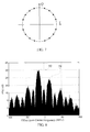
FIG. 7 illustrates a constellation of multiplexed baseband signal when the power ratio of the four signal components is c 1 : c 2 : c 3 : c 4=1: 2 : 3 : 8, according to an embodiment of the present application. -
FIG. 8 illustrates power spectral density (PSD) of multiplexed signal, according to an embodiment of the present application. -
FIG. 9 illustrates a flowchart of navigation satellite signal generating method, according to an embodiment of the present application. -
FIG. 10 illustrates a block diagram of navigation satellite signal receiving device, according to an embodiment of the present application. -
FIG. 11 illustrates a schematic diagram of an implementation of navigation satellite signal receiving device, according to an embodiment of the present application. - Hereinafter, with reference to the appended drawings, a detailed description on the satellite navigation signals, generating method, generating device, receiving method and receiving device will be presented. For simplicity, in the description of the embodiments of the present application, the same or similar reference numeral is used for the same or similar device.
-
FIG. 1 illustrates a navigation satellite signal generating device 1 according to an embodiment of the present application. As shown inFIG.1 , the signal generating device 1 includes abaseband signal generator 100, amultiplexed signal generator 200, and amodulator 300. Thebaseband signal generator 100 generates a first baseband signal S1, a second baseband signal S2, a third baseband signal S3 and a forth baseband signal S4. Themultiplexed signal generator 200 sets an amplitude and a phase of the in-phase baseband component I(t) and an amplitude and a phase of the quadrature-phase baseband component Q(t) of a multiplexed signal of the first baseband signal S1, the second baseband signal S2, the third baseband signal S3 and the forth baseband signal S4, so as to generate the multiplexed signal with constant envelope. Themodulator 300 modulates the multiplexed signal with constant envelope to the radio frequency, so as to generate the navigation satellite signal. In this way, the first baseband signal S1, and the second baseband signal S2 are modulated on a first carrier frequency f 1 with orthogonal carrier phases, the third baseband signal S3 and the forth baseband signal S4 are modulated on a second carrier frequency f 2 with orthogonal carrier phases. According to the navigation satellite signal generating device of the present application, it is possible to realize the constant envelope multiplexing of the four signal component (S1,S2,S3,S4) on the two frequency (f 1, f 2). - According to an embodiment, it is possible to set power parameters c 1 , c 2 , c 3 and c 4 of the baseband signals Si according to actual requirement. That is, baseband signals may have different power parameters. According to an embodiment, the power parameter may be an absolute power of the baseband signal, such as the actually adopted transmitting power of each baseband signal. According to another embodiment, the power parameter may be a relative power of the baseband signal. As it is understood, the absolute power of a signal changes after passing devices such as amplifier. For instance, when the power ratio c 1 : c 2 : c 3 : c 4 of the baseband signals is 1: 1: 1: 1, the relative power of each of the four baseband signals may be 1. When the power ratio c 1 : c 2 : c 3 : c 4 of the baseband signals is 1: 3: 1: 3, the relative powers of the four baseband signal may be 1, 3, 1 and 3, respectively. In addition, the baseband signals generated by the
baseband signal generator 110 may include one, two or three signals with the power parameter of zero. - The multiplexed
signal generator 200 may set the amplitude and phase of the in-phase baseband component and the amplitude and phase of the quadrature-phase baseband component of the multiplexed signal according to the power parameters of the baseband signals. - According to an embodiment, a baseband signal is the signal with value of +/-1. The multiplexed
signal generator 200 may set the amplitude and phase of the in-phase baseband component and the amplitude and phase of the quadrature-phase baseband component of the multiplexed signal according to the values of the baseband signals. - As shown in
FIG. 2 , according to an embodiment, thebaseband signal generator 100 may include asource 110, a spreadingmodulator 120 and a spreadingchip waveform generator 130. - The
source 110 generates the information to be broadcast, such as, synchronization word, time information, ephemeris, etc., which are necessary for the positioning of GNSS, and encodes them into bitstream. As can be understood by those skilled in the art, for some signals exclusively designed for purposes of ranging, such as the pilot channel in GNSS, it is allowed that the bitstream broadcast keeps constantly being 0 or 1 without transmitting specific information. - The spreading
modulator 120 modulates the bitstream/information generated by the source through using spreading sequence, so as to obtain the spreading sequence modulated with navigation messages. - The spreading
chip waveform generator 130 assigns a waveform to each bit of the spreading sequence with navigation messages. The waveform can be rectangular pulse, Return to Zero waveform, square wave, and the Binary-Coded Symbol (BCS) commonly used in GNSS, etc.. It is appreciated by those skilled in the art, the spreading chip waveforms used in the modulations of BPSK-R, BOC, TMBOC, etc. are particular examples of BCS waveform. As can be understood, the navigation satellite signal generating device of the present application allows a flexible choose of the spreading chip waveform used in the baseband signal components. - The output of the spreading
chip waveform generator 130 is a baseband signal with value of +/-1. As can be understood by those skilled in the art, the amplitude +/-1 of the baseband signal is not restrictive, and any enlargement or reduction in amplitude of the baseband signal does not depart from the scope of the present application. - According to an embodiment, the multiplexed
signal generator 200 may calculate the amplitude and phase of the in-phase baseband component I(t) and the amplitude and phase of the quadrature-phase baseband component Q(t) of the multiplexed signal, based on the power parameters of the baseband signal S1, S2, S3 and S4 and the values of the baseband signal S1, S2, S3 and S4, in order to generate the multiplexed signal with constant envelope. - As shown in the
FIG. 3 , the multiplexedsignal generator 200 may include acomputing unit 210, an in-phasechannel generating unit 220 and a quadrature-phasechannel generating unit 230. - The
computing unit 210 calculates the amplitude A (t) and phase ϕ(t) of the in-phase baseband component I(t), and calculates the amplitude A'(t) and phase ϕ'(t) of the quadrature-phase baseband component Q(t), based on the power parameters and values of the first baseband signal S1,the second baseband signal S2, the third baseband signal S3 and the forth baseband signal S4. - The in-phase
channel generating unit 220 generates the in-phase baseband component I(t), based on the amplitude A(t) and phase ϕ(t) calculated by thecomputing unit 210, wherein the in-phase baseband component I(t) is expressed as:
The quadrature-phasechannel generating unit 230 generates the quadrature-phase baseband component Q(t), based on the amplitude A(t) and phase ϕ(t) calculated by thecomputing unit 210, wherein the quadrature-phase baseband component Q(t) is expressed as:

- As can be understood, in this embodiment, the in-phase baseband component I(t) is a square wave function with the amplitude of A(t), the quadrature-phase baseband component Q(t) is a square wave function with the amplitude of A'(t) , and fs = |f 1 - f 2| / 2 stands for the frequency of the square wave.
- According to an embodiment, the
computing unit 210 calculates the amplitude A(t) and phase ϕ(t) of the in-phase baseband component I(t), and calculates the amplitude A'(t) and phase ϕ'(t) of the quadrature-phase baseband component Q(t) of the multiplexed signal, according to the following equations:


where si (t), i = 1, 2, 3, 4 stands for the i-th baseband signal, with the value of +/-1, ci stands for the power parameter of the i-th baseband signal Si, and atan2 is the four-quadrant arctangent function :
- As can be understood by those skilled in the art, in the perspective of the time domain, the multiplexed signal generated by the multiplexed
signal generator 200 can be expressed as: S(t) = I(t) + jQ(t), where I(t) is the in-phase baseband component of the multiplexed signal, and Q(t) is the quadrature-phase baseband component of the multiplexed signal. The envelope of the multiplexed signal is

signal generator 200. - In addition, the power parameters c 1 , c 2, c 3 and c4 of the baseband signal Si can be set according to the actual requirement. That is, different baseband signals may have different power parameters. Moreover, the baseband signals generated by the
baseband signal generator 110 may include one, two or three signals with the power parameter of zero. That is, any one, any two, or any three of the values c 1, c 2, c 3 and c 4 may be zero. - According to an embodiment of the present application, the
modulator 300 modulates the constant envelope multiplexed signal to a carrier of radio frequency, to generate the navigation satellite signal. - As shown in
FIG. 4 ,modulator 300 may include acarrier generator 310, afirst multiplier 321, asecond multiplier 322, and anadder 330. Themodulator 300 is used for modulating the multiplexed signal with constant envelope generated by the multiplexedsignal generator 200 to the radio frequency and then for transmitting. Thecarrier generator 310 generates the carrier with a central frequency of fRF = (f1 + f 2) / 2. - By using the
first multiplier 321, the in-phase baseband component I(t) of the multiplexed signal generated by the multiplexedsignal generator 200 is modulated to the carrier with the central frequency of fRF , for example, modulated to the carrier of cos(2πfRFt). By using thesecond multiplier 322, the quadrature-phase baseband component Q(t) of the multiplexed signal generated by the multiplexedsignal generator 200 is modulated to the carrier with the central frequency of fRF , for example, modulated to the carrier of sin(2πfRFt), whose phase is orthogonal to the phase of the carrier modulated by thefirst multiplier 321. The outputs of thefirst multiplier 321 and thesecond multiplier 322 are sent to theadder 330, so as to obtain the navigation satellite signal SRF with constant envelope, where the navigation satellite signal SRF is expressed as:
- In this way, the navigation satellite signal SRF transmitted by the satellite is the navigation satellite signal with constant envelope.
-
FIG. 5 illustrates a particular implementation of the navigation satellite signal generating device 1, according to an embodiment of the present application. - As shown in
FIG. 5 , the signal generating device 1 includes abaseband signal generator 100, a multiplexedsignal generator 200, and amodulator 300. Thebaseband signal generator 100 may include asource 110, a spreadingmodulator 120, a spreadingchip waveform generator 130. The multiplexedsignal generator 200 may include acomputing unit 210, an in-phase channel generator 220, and a quadrature-phase channel generator 230. Themodulator 300 may include acarrier generator 310, afirst multiplier 321, asecond multiplier 322, a π/2phase shiftingcircuit 323, and anadder 330. - Specifically, the
source 110 generates four binary navigation messages. As can be understood by those skilled in the art, if a pilot channel is used in some implementations, the navigation message of the corresponding channel keeps constant 0 or constant 1. Four navigation messages are transmitted into the spreading modulator 120-1, 120-2, 120-3, 120-4, respectively, for spreading spectral modulation, so as to obtain four spreading sequences with navigation message. The spreading sequences modulated with navigation message are transmitted to the spreading chip waveform generator 130-1, 130-2, 130-3, 130-4. Chip waveforming is made to the input spreading sequence modulated with the navigation message, then the output results can be noted as the baseband signals s 1(t), s 2(t), s 3(t), and s 4(t). - The
computing unit 210 receives the baseband signals s 1(t), s 2 (t), s 3(t), and s 4(t) from the spreading chip waveform generator 130-1, 130-2, 130-3, 130-4, and then calculates the amplitude A and phase offset ϕ of the in-phase baseband composite signal, and the amplitude A' and phase offset ϕ' of the quadrature-phase baseband composite signal, based on the power parameters of the baseband signal s 1(t), s 2(t), s 3(t), s 4(t), and the value s 1(t), s 2(t), s 3(t), s 4(t) at the current time. - The power parameters of the baseband signal s 1(t), s 2(t), s 3(t), s 4(t) may be set as any value according to actual requirements.
- The calculation rules can be expressed as:




- The in-
phase channel generator 220 receives the amplitude A(t) and phase offset ϕ(t) of the in-phase baseband composite signal from thecomputing unit 210, and outputs the in-phase baseband component of the multiplexed signal. That is, the output of the in-phase channel generator 220 can be expressed as
- The quadrature-
phase channel generator 230 receives the amplitude A'(t) and phase offset ϕ'(t) of the quadrature-phase baseband composite signal from thecomputing unit 210, and outputs the quadrature-phase baseband component of the multiplexed signal. That is, the output of the quadrature-phase channel generator 230 can be expressed as
- The
carrier generator 310 generates a carrier signal at the frequency fRF, and the carrier signal is divided into two branches. The carrier signal of thefirst branch 340 and the output of the in-phase channel generator 220 are input into thefirst multiplier 321. The carrier signal of thesecond branch 341, after passing through a π/2phase shifting circuit 323, turns into a carrier signal with a phase orthogonal to that of thebranch 340. The carrier signal of thesecond branch 341 and the output of the in-phase channel generator 230 are input into thesecond multiplier 322. The outputs of the two multipliers are input into theadder 330, so as to obtain anavigation satellite signal 339 with constant envelope. -
FIG. 6 illustrates another particular implementation of the navigation satellite signal generating device 1, according to an embodiment of the present application. In this implementation, the driving clock of modules is generated by division or multiplication of the reference frequency clock f 0, for clock synchronization. - As shown in
FIG. 6 , thebaseband signal generator 100 may include areference frequency clock 20, afrequency converter 21, a drive message generator 22, a frequency converter 23, a spreading modulator 24, afrequency converter 25, and a spreading chip waveform generator 26. The multiplexedsignal generator 200 may include a drive I-channel state selector 27, a Q-channel state selector 28, afrequency converter 29, afrequency converter 30, a first composite signal generator 31 and a second composite signal generator 32. Themodulator 300 may include a first multiplier 33, a second multiplier 34, a π/2phase shifting circuit 35, afrequency converter 36, a first carrier generator 37 and a first adder 38. - Specifically, the
reference frequency clock 20, through thefrequency converter 21, is converted into a data driving clock with a frequency fD, which drives the message generator 22 to generate four binary navigation messages. If a pilot channel is required in some implementations, the navigation message of the corresponding channel keeps constant 0 or constant 1. The reference frequency clock, through the frequency converter 23-1, 23-2, 23-3 and 23-4, is converted into the driving clock with frequency of f c1 , f c2, f c3 and f c4 , respectively, which drives the spreading modulator 24-1, 24-2, 24-3, and 24-4 to generate four binary spreading sequences, respectively, with the spreading code rate of f c1 , f c2, f c3 and f c4 . The spreading code rate is the positive integer multiple of fD . - The four navigation messages generated by the message generator 22 are transmitted into the spreading modulator 24-1, 24-2, 24-3 and 24-4 respectively, to make module-2 additive combination with the spreading sequence. The results of the
module 2 additive combination are sent into the spreading chip waveform generator 26-1, 26-2, 26-3, 26-4 respectively. The spreading chip waveform generator is driven by subcarrier driving clocks with the frequency of f sc1 , f sc2 , f sc3 and f sc4 , which are generated by sending theclock 20 into the frequency converter 25-1, 25-2, 25-3 and 25-4 respectively. The spreading chip waveform generator makes BCS chip waveform assignment to the spreading sequence modulated with navigation message, and the outputs are noted as baseband signals s 1(t), s 2(t), s 3(t), s 4(t) separately. Where f sc1 = K 1 f c1, f sc2 = K 2 f c2 , f sc3 = K 3 f c3 , f sc4 = K 4 f c4, and K 1 , K 2 , K 3 , K4 are integers greater than or equal to 1. - The
clock 20, through thefrequency converter 29, is converted to a driving clock with a frequency fM, which drives the I-channel state selector 27 and the Q-channel state selector 28. The fM is greater than the least common multiple fk of f sc1, f sc2 , f sc3 and f sc4 , and there is fM = MfK, where M is a positive integer. It is ensured that every phase-shifting point of the value of the si (t)(i=1, 2, 3, 4) is synchronous to fM . During the time slot t ∈ [n/fM,(n+1)/fM ), the sign si,n ∈ {+1,-1} of the value si (t) keeps invariant. - s 1(t), s 2(t), s 3(t), s 4(t) are sent into the I-channel state selector 27. The state selector 27 calculates the amplitude A and phase offset ϕ of the I-channel baseband composite signal, based on the power parameters and the values of s 1(t), s 2 (t), s 3(t), s 4(t) in the current time slot of the baseband signal. The calculation rules can be expressed as:


- The
clock 20, through thefrequency converter 30, is converted to a driving clock with a frequency fs, which drives the first composite signal generator 31 to generate the square wave subcarrier with the frequency of fs. The amplitude A and phase offset ϕ of the composite signal from the I-channel state selector 27 are sent into the first composite signal generator 31, so as to control the amplitude and phase offset of the square wave subcarrier generated by the first composite signal generator 31. The output of the first composite signal generator 31 can be expressed as:
- s 1(t), s 2(t), s 3(t), s 4(t) are sent into the Q-channel state selector 28. The state selector 28 calculates the amplitude A' and phase offset ϕ' of the Q-channel baseband composite signal, based on the power parameters and the values of s 1(t), s 2 (t), s 2(t), s 4(t) in the current time slot of the baseband signal. The calculation rules can be expressed as:


- The driving clock with the frequency fs drives the second composite signal generator 32 so as to generate the square wave subcarrier with the frequency of fs. The amplitude A' and phase offset ϕ' of the composite signal from the Q-channel state selector 28 are sent into the second composite signal generator 32, so as to control the amplitude and phase offset of the square wave subcarrier generated by the second composite signal generator 32. The output of the second composite signal generator 32 can be expressed as:

- The
reference clock 20, through thefrequency converter 36, is converted to a driving clock with a frequency fRF, which drives the first carrier generator 37 to generate a carrier with the frequency of fRF. The carrier signal is divided into two branches. The carrier signal of a branch 40 and the output of the first composite signal generator 31 are sent into the first multiplier 33. The carrier signal of the other branch 41, after passing through the π/2phase shifting circuit 35, turns into a carrier signal with a phase orthogonal to that of the branch 40. The carrier signal of the other branch 41 and the output of the second composite signal generator 32 are sent into the second multiplier 34. The outputs of the two multipliers are sent into the first adder 38 so as to generate the navigation satellite signal 39 with constant envelope. -
FIG. 7 illustrates the Fresnel constellation of the multiplexed baseband signal with c 1 : c 2 : c 3 : c 4 =1 : 2 : 3 : 8. As shown, the multiplexed signal under this condition is a 16-PSK signal, while the constellation points are not uniformly distributed. When other values are set for c 1 : c 2 : c 3 : c 4, the number of constellation points and the distribution of the constellation points can be different from that in the present example. -
FIG. 8 illustrates the power spectral density (PSD) of the multiplexed baseband signal with c 1 : c 2 : c 3 : c 4 = 1 : 2 : 3 : 8, f c1 = f c2 = f c3 = f c4 = 10.23 MHz, rectangular pulse spreading waveform (i.e. BPSK-R modulation) adopted for each signal component, and fs =15.345 MHz. In the PSD, the two signal components sharing the same frequency are added together and difficult to be distinguished from each other. However, in the present embodiment, the power of the upper sidebandmain lobe 51 with the central frequency of f 1 is about 5.5dB lower than that of the lower sidebandmain lobe 50 with the central frequency of f 2, corresponding to the design specifications that the ratio between the total power of the upper sideband signal components and the total power of the lower sideband signal components is (c 1 + c 2) / (c 3 + c 4) = 3/11 (-5.6dB). Thus, according to the navigation satellite signal generating method presented in the application, the constant envelope multiplexing (CEM) of four signal components with different power can be achieved. - Another aspect of the present application provides a navigation satellite signal generating method. According to this method, the CEM of the four signal components (S1,S2,S3,S4) on two frequencies (f 1, f 2) can be achieved.
-
FIG. 9 illustrates a flowchart of the navigation satellite signal generating method, according to an embodiment of the present application. As shown inFIG.9 , inStep 901, a first baseband signal S1, a second baseband signal S2, a third baseband signal S1, and a forth baseband signal S4 are generated. InStep 902, an amplitude and a phase of an in-phase baseband component of and an amplitude and a phase of a quadrature-phase baseband component of a signal multiplexed of the first baseband signal S1, the second baseband signal S2, the third baseband signal S3, and the forth baseband signal S4 are set, in order to generate a multiplexed signal with constant envelope. InStep 903, the multiplexed signal with constant envelope is modulated to radio frequency, so as to generate a navigation satellite signal. Here, the first baseband signal S1 and the second baseband signal S2 are modulated on a first carrier frequency f 1 with carrier phases thereof orthogonal to each other, the third baseband signal S3 and the forth baseband signal S4 are modulate on a second carrier frequency f 2 with carrier phases thereof orthogonal to each other. - According to an embodiment, the powers c 1 , c 2, c 3 and c 4 of baseband signals Si can be set according to actual requirements. In
Step 902, the amplitudes and phases of the in-phase baseband component and quadrature-phase baseband component of the multiplexed signal may be set according to the power parameters of the baseband signals. - According to an embodiment, in
Step 902, the amplitudes and phases of the in-phase baseband component and quadrature-phase baseband component of the multiplexed signal may be set according to the values of the baseband signals. - According to an embodiment, in
Step 903, the multiplexed signal with constant envelope may be modulated to the carrier with a central frequency of fRF = (f 1 + f 2) / 2, so as to generate the navigation satellite signal. - According to an embodiment of the present application, the navigation satellite signal generating method further includes: calculating the amplitude A(t) and phase ϕ(t) of the in-phase baseband component I(t), and calculating the amplitude A'(t) and phase ϕ'(t) of the quadrature-phase baseband component Q(t), based on the power parameters and values of the first baseband signal S1,the second baseband signal S2, the third baseband signal S3 and the forth baseband signal S4; and generating the in-phase baseband component I(t), based on the calculated amplitude A(t)and phase ϕ(t), where the in-phase baseband component I(t) is expressed as

and generating the quadrature-phase baseband component Q(t) based on the calculated amplitude A'(t)and phase ϕ'(t), where the quadrature-phase baseband component Q(t) is expressed as
where fs = |f 1 - f 2|/ 2, sgn stands for the sign function
- According to an embodiment of the present application, the navigation satellite signal generating method further includes: calculating the amplitude A(t) and phase ϕ(t) of the in-phase baseband component I(t), and calculating the amplitude A'(t)and phase ϕ'(t) of the quadrature-phase baseband component Q(t), according to the following equations


where si (t), i = 1, 2, 3, 4 stands for the i-th baseband signal Si, ci stands for the power parameters of the i-th baseband signal Si; and atan2 is the four-quadrant arctangent function:
- While embodiments and specific implementations of the navigation satellite signal generating method and generating device are described as above referring to the drawings, it should be understood that they have been presented by way of example only, but not limitation. It will be apparent to those skilled in the art that various changes in form and detail can be made therein without departing from the spirit and scope of the invention.
- Embodiments of the present application described above have focused on the transmission side, that is, upon navigation satellite signal generating methods and generating devices. In addition, embodiments of the present application also relate to signals generated by the navigation satellite signal generating methods and generating devices as those described above.
- Moreover, those skilled in the art appreciates that converse system, method, apparatus and receiver are required to receive and process the signals generated by the aforementioned navigation satellite signal generating methods and generating devices. Therefore, embodiments of the present application also relate to systems, methods, apparatuses and receiving devices used for processing navigation satellite signals as those described above.
- According to an embodiment of the present application, a navigation satellite signal receiving device is provided, in order to receive the navigation satellite signal generated by the aforementioned navigation satellite signal generating methods or the generating devices. In this embodiment, the signal components modulated on the first carrier and the second carrier can be processed respectively. As shown in
FIG. 10 , asignal receiving device 500 includes a receivingunit 510, ademodulation unit 520, and aprocessing unit 530. Here, the receivingunit 510 receives the navigation satellite signal; the demodulation unit 521 demodulates the signal component modulated on the first carrier of the received navigation satellite signal, and demodulates the signal component modulated on the second carrier of the received navigation satellite signal; and theprocessing unit 530 obtains the first baseband signal S1 and the second baseband signal S2, according to the signal component modulated on the first carrier which is demodulated by the demodulation unit, and obtains the third baseband signal S3 and the forth baseband signal S4, according to the signal component modulated on the second carrier which is demodulated by the demodulation unit. -
FIG. 11 illustrates the schematic diagram of a particular implementation of navigation satellite signal receiving device, according to an embodiment of the present application. According to the embodiment, the receivingunit 510 may include anantenna 61; thedemodulation unit 520 may include afiltering amplification unit 62, adownconverter 63, and an Analog to Digital Converter (ADC) 64; and theprocessing unit 530 may include a digitalsignal processing module 65. - Referring to
FIG. 11 , when signal components are received separately, thenavigation satellite signal 60 is received fromantenna 61. After received by theantenna 61, the receivednavigation satellite signal 60 is sent into thefiltering amplification unit 62, where thenavigation satellite signal 60 is filtered, in order to resist the strong interference signals and out of band noises, and then thenavigation satellite signal 60 is amplified. When processing the upper sideband signal component s 1(t) or s 2(t), the central frequency of the filtering unit is set near f 1, with bandwidth greater than or equal to the bandwidth of the signal component s 1(t) or s 2(t) to be received, in order to ensure that enough power of the signal component s 1(t) or s 2(t) passes the filtering unit; similarly, when processing the upper sideband signal component s 3(t) or s 4(t) the central frequency of filter is set near f 2 , with bandwidth greater than or equal to the bandwidth of the signal component s 3(t) or s 4(t) to be received, in order to ensure that enough power of the signal component s3 (t) or s 4(t) passes the filtering unit. - The filtered and amplified signal from the
filtering amplification unit 62 is sent into thedownconverter 63, in order to convert the carrier frequency of the signal component to a corresponding Intermediate Frequency (IF); then the signal is sent into theADC 64 for the sampling and quantization of the signal, and a digital IF signal is obtained. - The digital IF signal from the
ADC 64 is sent into the digitalsignal processing module 65. This module can be implemented by FPGA, ASIC, universal computing unit or the combination of the aforementioned devices, so as to achieve the corresponding acquisition, tracking, demodulation to the baseband signal component to be processed. - Moreover, according to an embodiment of the present application, a navigation satellite signal receiving method is provided, to receive the navigation satellite signal generated by the aforementioned navigation satellite signal generating method or generating device. The signal receiving method includes: receiving the navigation satellite signal; demodulates a signal component modulated on a first carrier of the received navigation satellite signal, so as to obtain a first baseband signal S1, and a second baseband signal S2; and demodulates a signal component modulated on a second carrier of the received navigation satellite signal, so as to obtain a third baseband signal S3 and a forth baseband signal S4.
- According to an embodiment of the present application, a navigation satellite signal receiving device is provided, in order to receive the navigation satellite signal generated by the aforementioned navigation satellite signal generating method or the generating device. In this embodiment, the received navigation satellite signal with a central frequency of (f 1 + f 2)/2 can be processed as a whole. As shown in the
FIG. 10 , thesignal receiving device 500 includes a receivingunit 510, ademodulation unit 520, and aprocessing unit 530. Here, the receivingunit 510 receives the navigation satellite signal; thedemodulation unit 520 demodulates navigation satellite signal, so as to obtain an in-phase baseband component and a quadrature-phase baseband component of the multiplexed signal; and theprocessing unit 530 obtains a first baseband signal S1, a second baseband signal S2, a third baseband signal S3 and a forth baseband signal S4, according to an amplitude and a phase of the in-phase baseband component and an amplitude and a phase of the quadrature-phase baseband component of the multiplexed signal. - As can be understood, since the value of the baseband signal is +/-1, the combination of four baseband signal values [S1, S2, S3, S4] may have up to 16 combination states. The
processing unit 530 may, for an in-phase and quadrature-phase baseband component local replica corresponding to each of the 16 combination states, calculate a correlation between the in-phase and quadrature-phase baseband component local replica and the in-phase and quadrature-phase baseband component obtained from the demodulation unit 540, so as to determine values of the received first baseband signal S1, the second baseband signal S2, the third baseband signal S3, and the forth baseband signal S4. - Referring to
FIG. 11 again, when the multiplexed signal is received and processed as a whole, thenavigation satellite signal 60 is received from theantenna 61 in the receiver. The receivednavigation satellite signal 60 from theantenna 61 is sent into thefiltering amplification unit 62, for filtering thenavigation satellite signal 60 to resist the strong interference signals and out of band noises, and for amplifying thenavigation satellite signal 60. The central frequency of filtering unit is set near (f 1 + f 2)/2, with a bandwidth greater than or equal to 2fs , to ensure that enough power of the whole complexed signal passes the filtering unit. If the design of the filtering unit allows, it is suggested to ensure that the first main lobe power of every signal component passes the filtering unit. - The filtered and amplified signal from the
filtering amplification unit 62 is sent into thedownconverter 63, to convert the carrier frequency of the signal component to an Intermediate Frequency (IF); then the signal is sent into theADC 64 for the sampling and quantization of the signal, to obtain a digital IF signal. - The digital IF signal from the
ADC 64 is sent into the digitalsignal processing module 65. This module can be implemented by FPGA, ASIC, universal computing unit or the combination of the aforementioned devices. The digital IF signal is multiplied by the in-phase carrier and quadrature-phase carrier generated by the receiver, in order to remove the IF and Doppler of the digital signal, so as to obtain the receiver in-phase baseband signal SI(t) and the receiver quadrature-phase baseband signal SQ(t). - The digital
signal processing module 65 is configured to generate spreading sequences of four signal components with spreading chip waveform assignment. According to all the possible value combinations of the binary baseband local signal replica of the four signal components, the in-phase baseband waveform local replica Ĩi(t) and the quadrature-phase baseband waveform local replica Q̃i (t) are generated by the digitalsignal processing module 65 corresponding to each combination, at each epoch. The total number of value combinations is noted as g. It can be calculated that if N signal components relate to data channels, there is g= 2 N . For a specific instance among the g value combinations of Si = {s̃ 1, s̃ 2, s̃ 3 , s̃ 4}, the generating rule of Ĩi (t) and Q̃i (t) is

where


- The i-th (i=1,2,...,g) group of the in-phase baseband waveform local replica Ĩi (t) is multiplied by the receiver in-phase baseband signal SI(t) and receiver quadrature-phase baseband signal SQ(t) respectively, and the results are sent into the integration-dump filter for coherent integration with the duration of TI, then the i-th (i=1,2,...,g) group of the first in-phase correlation value corr1Ii and quadrature-phase correlation value corr1Qi are obtained; similarly, each group of the quadrature-phase baseband waveform local replica Q̃i (t) is multiplied by the receiver in-phase baseband signal SI(t) and receiver quadrature-phase baseband signal SQ(t) respectively, and the results are sent into the integration-dump filter for coherent integration with the duration of TI, then the i-th (i=1,2,...,g) group of the second in-phase correlation value corr2Ii and quadrature-phase correlation value corr2Qi are obtained.
- The seven step, the i-th (i=1,2,...,g) group of the first in-phase correlation value corr1Ii and the first quadrature-phase correlation value corr1Qi, the second in-phase correlation value corr2Ii and the second quadrature-phase correlation value corr2Qi are combined according to the following rule, so as to obtain the i-th (i=1,2,...,g) group of the in-phase combination correlation value


- If


- Moreover, according to an embodiment of the present application, a navigation satellite signal receiving method is provided, so as to receive the navigation satellite signal generated by the aforementioned navigation satellite signal generating method or generating device. The signal receiving method includes: receiving the navigation satellite signal; demodulating the navigation satellite signal, so as to obtain an in-phase baseband component of and a quadrature-phase baseband component of the multiplexed signal; and obtaining a first baseband signal S1, a second baseband signal S2, a third baseband signal S3 and a forth baseband signal S4, according to an amplitude and a phase of the in-phase baseband component of and an amplitude and a phase of the quadrature-phase baseband component of the multiplexed signal.
- While embodiments and specific implementations of the navigation satellite signal receiving method and receiving device are described as above referring to the drawings, it should be understood that they have been presented by way of example only, and not limitation. Moreover, those skilled in the art appreciates that converse system, method, apparatus and receiver are required to receive and process the signals generated by the aforementioned navigation satellite signal generating methods and generating devices. Therefore, embodiments of the present application relate to any systems, methods apparatuses and receiving devices used for processing navigation satellite signals as those described above.
- Embodiments of the present application may be implemented by hardware, software or the combination thereof. An aspect of the present application provides a program including executable instructions to implement the satellite navigation signal generating method, generating device, the satellite navigation signal receiving method, receiving device according to embodiments of the present application. In addition, the program can be stored in storage of any form, such as optical or magnetic readable media, chip, ROM, PROM, or any form of volatile or non-volatile memory device. According to an example of the embodiment of the present application, a machine-readable storage is provided for storing the program.
- While various embodiments of the present application have been described above referring to the drawings, it should be understood that they have been presented by way of example only, and not limitation. It will be apparent to those skilled in the art that various changes in form and detail can be made therein without departing from the spirit and scope of the invention.
Claims (30)
- A navigation satellite signal generating device, comprising:a baseband signal generator to generate a first baseband signal S1, a second baseband signal S2, a third baseband signal S3, and a forth baseband signal S4;a multiplexed signal generator to set an amplitude and a phase of an in-phase baseband component and an amplitude and a phase of a quadrature-phase baseband component of a signal into which the first baseband signal S1, the second baseband signal S2, the third baseband signal S3 and the forth baseband signal S4 are multiplexed, so as to generate a multiplexed signal with constant envelope; anda modulator to modulate the multiplexed signal with constant envelope to a radio frequency, so as to generate the navigation satellite signal,wherein the first baseband signal S1 and the second baseband signal S2 are modulated to a first carrier frequency f1 with carrier phases orthogonal to each other, and the third baseband signal S3 and the forth baseband signal S4 are modulated to a second carrier frequency f2 with carrier phases orthogonal to each other.
- The navigation satellite signal generating device as claimed in claim 1, wherein the amplitude and the phase of the in-phase baseband component and the amplitude and the phase of the quadrature-phase baseband component of the multiplexed signal are set by the multiplexed signal generator, based on power parameters of the baseband signals.
- The navigation satellite signal generating device as claimed in claim 2, wherein the power parameters are absolute powers of the baseband signals or relative powers of the baseband signals.
- The navigation satellite signal generating device as claimed in claim 3, wherein the power parameters of any one, any two or any three of the baseband signals are zero, or the power parameter of each of the four baseband signals is non-zero.
- The navigation satellite signal generating device as claimed in claim 2, wherein the amplitude and the phase of the in-phase baseband component and the amplitude and the phase of the quadrature-phase baseband component of the multiplexed signal are set by the multiplexed signal generator, based on values of the baseband signals.
- The navigation satellite signal generating device as claimed in claim 5, wherein the multiplexed signal generator includes:a computing unit, to calculate the amplitude A(t) and the phase ϕ(t) of the in-phase baseband component I(t), and to calculate the amplitude A'(t) and the phase ϕ'(t) of the quadrature-phase baseband component Q(t), based on the power parameters and values of the first baseband signal S1, the second baseband signal S2, the third baseband signal S3 and the forth baseband signal S4;an in-phase channel generating unit, to generate the in-phase baseband component I(t), based on the amplitude A(t) and phase ϕ(t) calculated by the computing unit, wherein the in-phase baseband component I(t) is expressed as

anda quadrature-phase channel generating unit, to generate the quadrature-phase baseband component Q(t), based on the amplitude A'(t) and the phase ϕ'(t) calculated by the computing unit, wherein the quadrature-phase baseband component Q(t) is expressed as wherein fs = |f 1 - f 2|/ 2, sgn stands for the sign function , and
- The navigation satellite signal generating device as claimed in claim 6, wherein the computing unit calculates the amplitude A(t) and the phase ϕ(t) of the in-phase baseband component I(t), and calculates the amplitude A'(t) and the phase ϕ'(t) of the quadrature-phase baseband component Q(t), according to equations of:


and

wherein si (t), i = 1, 2, 3, 4 stands for the i-th baseband signal S1, ci stands for the power parameter of the i-th baseband signal Si;
wherein atan2 is the four-quadrant arctangent function,
- The navigation satellite signal generating device as claimed in claim 1, wherein the baseband signal generator includes:a source to generate messages to be broadcast;a spreading modulator to modulate the messages generated by the source by using a spreading sequence; anda spreading chip waveform generator to assign a waveform to each bit of the spreading sequence modulated with navigation messages, to generate a baseband signal.
- The navigation satellite signal generating device as claimed in claim 1, wherein the modulator includes:a carrier generator to generate a carrier of radio frequency;a first multiplier to modulate the in-phase baseband component of the multiplexed signal generated by the multiplexed signal generator to the carrier of radio frequency;a second multiplier to modulate the quadrature-phase baseband component of the multiplexed signal generated by the multiplexed signal generator to the carrier of radio frequency; andan adder to add together the in-phase baseband component of the multiplexed signal modulated to the carrier of radio frequency and the quadrature-phase baseband component of the multiplexed signal modulated to the carrier of radio frequency, so as to generate the navigation satellite signal.
- A navigation satellite signal generating method, comprising:generating a first baseband signal S1, a second baseband signal S2, a third baseband signal S3, and a forth baseband signal S4;setting an amplitude and a phase of an in-phase baseband component and an amplitude and a phase of a quadrature-phase baseband component of a signal into which the first baseband signal S1, the second baseband signal S2, the third baseband signal S3 and the forth baseband signal S4 are multiplexed, so as to generate a multiplexed signal with constant envelope; andmodulating the multiplexed signal with constant envelope to a radio frequency, so as to generate the navigation satellite signal,wherein the first baseband signal S1 and the second baseband signal S2 are modulated to a first carrier frequency f1 with carrier phases orthogonal to each other, and the third baseband signal S3 and the forth baseband signal S4 are modulated to a second carrier frequency f2 with carrier phases orthogonal to each other.
- The navigation satellite signal generating method as claimed in claim 10, wherein said setting step includes: setting the amplitude and the phase of the in-phase baseband component and the amplitude and the phase of the quadrature-phase baseband component of the multiplexed signal, based on power parameters of the baseband signals.
- The navigation satellite signal generating method as claimed in claim 11, wherein the power parameters are absolute powers of the baseband signals or relative powers of the baseband signals.
- The navigation satellite signal generating method as claimed in claim 12, wherein the power parameters of any one, any two or any three of the baseband signals are zero, or the power parameter of each of the four baseband signals is non-zero.
- The navigation satellite signal generating method as claimed in claim 11, wherein said setting includes: setting the amplitude and the phase of the in-phase baseband component and the amplitude and the phase of the quadrature-phase baseband component of the multiplexed signal, based on values of the baseband signals.
- The navigation satellite signal generating method as claimed in claim 14, further comprising:calculating the amplitude A(t) and the phase ϕ(t) of the in-phase baseband component I(t), and calculating the amplitude A'(t) and the phase ϕ'(t) of the quadrature-phase baseband component Q(t), based on the power parameters and values of the first baseband signal S1, the second baseband signal S2, the third baseband signal S3 and the forth baseband signal S4;generating, based on the calculated amplitude A(t) and phase ϕ(t), an in-phase baseband component I(t), which is expressed as

andgenerating, based on the calculated amplitude A'(t) and the phase ϕ'(t), a quadrature-phase baseband component Q(t), which is expressed as wherein fs = |f 1 - f 2|/ 2, sgn stands for the sign function, and
- The navigation satellite signal generating method as claimed in claim 15, further comprising:calculating the amplitude A(t) and the phase ϕ(t) of the in-phase baseband component I(t), and calculating the amplitude A'(t) and the phase ϕ'(t) of the quadrature-phase baseband component Q(t), according to equations of:


and
 wherein si (t), i = 1, 2, 3, 4 stands for the i-th baseband signal S1, ci stands for the power parameter of the i-th baseband signal Si;wherein atan2 is the four-quadrant arctangent function,
- The navigation satellite signal generating method as claimed in claim 10, wherein said generating step includes:generating messages to be broadcast;modulating the messages generated by a source by using a spreading sequence; andassigning a waveform to each bit of the spreading sequence modulated with navigation messages, to generate a baseband signal.
- The navigation satellite signal generating method as claimed in claim 10, wherein said modulating step includes:generating a carrier of radio frequency;modulating the in-phase baseband component of the multiplexed signal to the carrier of radio frequency;modulating the quadrature-phase baseband component of the multiplexed signal to the carrier of radio frequency; andadding together the in-phase baseband component of the multiplexed signal modulated to the carrier of radio frequency and the quadrature-phase baseband component of the multiplexed signal modulated to the carrier of radio frequency, so as to generate the navigation satellite signal.
- A navigation satellite signal generated by the navigation satellite signal generating method or navigation satellite signal generating device as claimed in any preceding claim.
- An apparatus comprising means adapted to process a navigation satellite signal as claimed in any preceding claim or a navigation satellite signal generated by using the navigation satellite signal generating method or generating device as claimed in any preceding claim.
- A navigation satellite signal receiving device to receive a navigation satellite signal as claimed in any preceding claim or a navigation satellite signal generated by using the navigation satellite signal generating method or the generating device as claimed in any preceding claim.
- A signal receiving device to receive a navigation satellite signal as claimed in any preceding claim, or a navigation satellite signal generated by using the navigation satellite signal generating method or the generating device as claimed in any preceding claim, comprising:a receiving unit to receive the navigation satellite signal;a demodulation unit to demodulate a signal component modulated on a first carrier of the navigation satellite signal received by the receiving unit, and to demodulate a signal component modulated on a second carrier of the navigation satellite signal received by the receiving unit; anda processing unit to obtain a first baseband signal S1 and a second baseband signal S2 based on the signal component modulated on the first carrier which is demodulated by the demodulation unit, and to obtain a third baseband signal S3 and a forth baseband signal S4 based on the signal component modulated on the second carrier which is demodulated by the demodulation unit.
- A signal receiving method of receiving a navigation satellite signal as claimed in any preceding claim, or a navigation satellite signal generated by using the navigation satellite signal generating method or the generating device as claimed in any preceding claim, comprising:receiving the navigation satellite signal;demodulating a signal component modulated on a first carrier of the received navigation satellite signal to obtain a first baseband signal S1 and a second baseband signal S2; anddemodulating a signal component modulated on a second carrier of the received navigation satellite signal to obtain a third baseband signal S3 and a forth baseband signal S4.
- A signal receiving device to receive a navigation satellite signal as claimed in any preceding claim, or a navigation satellite signal generated by using the navigation satellite signal generating method or generating device as claimed in any preceding claim, comprising:a receiving unit to receive the navigation satellite signal;a demodulation unit to demodulate the navigation satellite signal so as to obtain an in-phase baseband component and a quadrature-phase baseband component of the multiplexed signal; anda processing unit to obtain a first baseband signal S1, a second baseband signal S2, a third baseband signal S3 and a forth baseband signal S4, based on an amplitude and a phase of the in-phase baseband component and an amplitude and a phase of the quadrature-phase baseband component of the multiplexed signal.
- A signal receiving method of receiving a navigation satellite signal as claimed in any preceding claim, or a navigation satellite signal generated by using the navigation satellite signal generating method or the generating device as claimed in any preceding claim, comprising:receiving the navigation satellite signal;demodulating the navigation satellite signal to obtain an in-phase baseband component and a quadrature-phase baseband component of the multiplexed signal; andobtaining a first baseband signal S1, a second baseband signal S2, a third baseband signal S3 and a forth baseband signal S4, based on an amplitude and a phase of the in-phase baseband component and an amplitude and a phase of the quadrature-phase baseband component of the multiplexed signal.
- A signal receiving method of receiving a navigation satellite signal as claimed in any preceding claim, or a navigation satellite signal generated by using the navigation satellite signal generating method or the generating device as claimed in any preceding claim, comprising:receiving, filtering and then amplifying the navigation satellite signal, wherein a central frequency of the filtering is set at (f 1 + f 2)/2;converting a carrier frequency of the signal component to be processed to a corresponding intermediate frequency, and converting the signal component from analog to digital by sampling and quantizing the signal;multiplying the converted digital intermediate frequency signal by an in-phase carrier and a quadrature-phase carrier respectively, so as to obtain a receiver in-phase baseband signal SI(t) and a receiver quadrature-phase baseband signal SQ(t);generating a spreading sequence of four signal component with spreading chip waveform assignment by using a digital signal processor based on the converted digital intermediate frequency signal, and according to all the possible value combinations of the binary baseband local signal replica of the four signal components, generating an in-phase baseband waveform local replica Ĩq (t) and a quadrature-phase baseband waveform local replica Q̃q(t) corresponding to each combination, at each epoch,wherein the number of value combinations is noted as g, g ≤ 16, and for a special case


 where,



 ci, i = 1, 2, 3, 4 is the power parameter of i-th baseband signal,wherein each group of the in-phase baseband waveform local replica Ĩq (t) is multiplied by the receiver in-phase baseband signal SI(t) and receiver quadrature-phase baseband signal SQ(t) respectively, and the results are processed for coherent integration with the duration of TI, then a q-th (q=1,2,...,g) group of a first in-phase correlation value corr1Iq and a first quadrature-phase correlation value corr1Qq are obtained; each group of the quadrature-phase baseband waveform local replica Q̃q(t) is multiplied by the receiver in-phase baseband signal SI(t) and receiver quadrature-phase baseband signal SQ(t) respectively, and the results are processed for coherent integration with the duration of TI, then a q-th (q=1,2,...,g) group of a second in-phase correlation value corr2Iq and a second quadrature-phase correlation value corr2Qq are obtained;combining the first in-phase correlation value corr1Iq and the first quadrature-phase correlation value corr1Qq, and combining the second in-phase correlation value corr2Iq and the second quadrature-phase correlation value corr2Qq, according to the following rule
 obtaining a q-th group of the in-phase combination correlation value
 selecting a group of


- A program comprising executable instructions to implement the method, device, apparatus in any preceding claim, or to generate a signal in any preceding claim.
- A machine-readable storage for storing a program as claimed in claim 27.
- A method of multiplexing navigation satellite signal with constant envelope, comprising:generating baseband spreading signals si (t) i = 1, 2, 3, 4 for signal components, wherein carrier phases of s 1 (t) and s 2(t) are orthogonal to each other, and carrier phases of s 3(t) and s 4(t) are orthogonal to each other;based on a drive of a driving clock with the frequency of fM, multiplexing the baseband spreading signal si (t), generating a multiplexed in-phase baseband waveform I(t) and a multiplexed quadrature-phase baseband waveform Q(t) according to the sign si,n ∈ {+1,-1} of the value si(t) during a time slot t,wherein the frequency of fM is the least common multiple of the reciprocal of the minimum hold time of the sign of si (t), so as to ensure that each phase-shifting point of the value of the si (t)(i=1, 2, 3, 4) is synchronous to fM, wherein n is an integer greater than or equal to zero, and the sign s i,n ∈ {+1,-1} of the value si (t) keeps constant during the time slot t, t ∈ [n / fM, (n + 1) / fM ),based on a drive of a carrier driving clock with the frequency of fP = (f 1 + f 2 )/2, generating, using a carrier generator, two carriers cos(2πfPt) and sin (2πfPt) with phases orthogonal to each other, and multiplying the two carriers by the multiplexed in-phase baseband waveform I(t) and the multiplexed quadrature-phase baseband waveform Q(t) respectively, and then making additive combination of the multiplied results, so as to obtain a signal SRF (t) in radio frequency with constant envelope, wherein f 1 is a central frequency of s 1(t) and s 2(t) of the signal with constant envelope modulated to radio frequency, and f 2 is a central frequency of s 3(t) and s 4(t) of the signal with constant envelope modulated to radio frequency.
- The method as claimed in claim 29, where the multiplexed in-phase baseband waveform I(t) and the multiplexed quadrature-phase baseband waveform Q(t) are:


wherein fs = (f 1 - f 2)/2, sgn stands for the sign function,
and


wherein atan2 is the four-quadrant arctangent function
Applications Claiming Priority (2)
| Application Number | Priority Date | Filing Date | Title |
|---|---|---|---|
| CN201210186757.5A CN102694569B (en) | 2012-06-07 | 2012-06-07 | Constant envelop multiplexing method, generating device and receiving method for navigation signal |
| PCT/CN2013/000675 WO2013181932A1 (en) | 2012-06-07 | 2013-06-06 | Satellite navigation signal and generation method, generation device, receiving method and receiving device therefor |
Publications (3)
| Publication Number | Publication Date |
|---|---|
| EP2866400A1 true EP2866400A1 (en) | 2015-04-29 |
| EP2866400A4 EP2866400A4 (en) | 2016-03-09 |
| EP2866400B1 EP2866400B1 (en) | 2019-05-22 |
Family
ID=46859865
Family Applications (1)
| Application Number | Title | Priority Date | Filing Date |
|---|---|---|---|
| EP13800415.5A Active EP2866400B1 (en) | 2012-06-07 | 2013-06-06 | Satellite navigation signal and generation method, generation device, receiving method and receiving device therefor |
Country Status (14)
| Country | Link |
|---|---|
| US (1) | US9137081B2 (en) |
| EP (1) | EP2866400B1 (en) |
| JP (1) | JP5858511B2 (en) |
| KR (1) | KR101595213B1 (en) |
| CN (2) | CN102694569B (en) |
| AU (1) | AU2013271243B2 (en) |
| BR (1) | BR112014029949B1 (en) |
| CA (1) | CA2875900C (en) |
| IN (1) | IN2014DN11129A (en) |
| MY (1) | MY171170A (en) |
| NZ (1) | NZ703463A (en) |
| RU (1) | RU2579442C1 (en) |
| WO (1) | WO2013181932A1 (en) |
| ZA (1) | ZA201409535B (en) |
Cited By (4)
| Publication number | Priority date | Publication date | Assignee | Title |
|---|---|---|---|---|
| CN105005057A (en) * | 2015-08-03 | 2015-10-28 | 北京理工大学 | Beidou navigation system D1 navigation message capture method |
| CN110071887A (en) * | 2019-05-14 | 2019-07-30 | 济南市半导体元件实验所 | The intensive modulating device of carrier phase and method |
| CN112068159A (en) * | 2020-08-25 | 2020-12-11 | 西安空间无线电技术研究所 | Navigation satellite signal quality on-orbit optimization method |
| GB2624195A (en) * | 2022-11-09 | 2024-05-15 | Qinetiq Ltd | Signal processor |
Families Citing this family (26)
| Publication number | Priority date | Publication date | Assignee | Title |
|---|---|---|---|---|
| CN102694569B (en) * | 2012-06-07 | 2014-05-14 | 清华大学 | Constant envelop multiplexing method, generating device and receiving method for navigation signal |
| CN103023598B (en) * | 2012-11-23 | 2016-03-30 | 清华大学 | The permanent envelope multiplex method of double frequency four component spread-spectrum signal, device and method of reseptance |
| CN104702311B (en) | 2013-12-06 | 2017-08-11 | 清华大学 | Generation method, generating means, method of reseptance and the reception device of spread-spectrum signal |
| US9184973B2 (en) * | 2014-01-10 | 2015-11-10 | Deere & Company | Method and receiver for receiving a binary offset carrier composite signal |
| CN104539567B (en) * | 2014-12-23 | 2017-10-17 | 电子科技大学 | A kind of 1090ES signal expansion methods based on phase-modulation |
| CN105589083A (en) * | 2015-12-04 | 2016-05-18 | 航天恒星科技有限公司 | Navigation satellite positioning calculation method and device |
| CN105676252B (en) * | 2016-01-19 | 2018-11-20 | 施浒立 | A kind of navigation signal source for signal blocks region |
| CN107037448B (en) * | 2016-02-03 | 2019-10-15 | 清华大学 | Method and device for generating dual-frequency constant-envelope navigation signal, method and device for receiving it |
| CN106772484B (en) * | 2016-12-29 | 2019-09-06 | 西安空间无线电技术研究所 | Adjustment method of power ratio and carrier phase relationship among multiple components of satellite navigation signal |
| KR20180097048A (en) | 2017-02-22 | 2018-08-30 | 국방과학연구소 | System and method for providing service multiplexing of tiered polyphase code structure |
| CN111025349A (en) * | 2018-10-09 | 2020-04-17 | 泰斗微电子科技有限公司 | BOC signal demodulation method and chip and equipment thereof |
| CN111107029B (en) * | 2018-10-25 | 2022-10-14 | 深圳市中兴微电子技术有限公司 | Orthogonal frequency division multiplexing demodulator, demodulation method and receiver |
| CN109412995B (en) * | 2018-11-29 | 2020-05-12 | 北京邮电大学 | Multi-stream quasi-constant envelope multi-carrier transmission method based on variable sub-carrier bandwidth |
| CN111381265B (en) * | 2018-12-29 | 2022-07-29 | 泰斗微电子科技有限公司 | A positioning solution method, device and satellite navigation receiver |
| CN112422230B (en) * | 2019-08-22 | 2024-05-03 | 中兴通讯股份有限公司 | Data frame detection method, device and storage medium |
| KR102400812B1 (en) * | 2020-10-19 | 2022-05-23 | 한국항공우주연구원 | method for mutilplexing signals, method for transmitting signals, and satellite |
| CN114137583B (en) * | 2021-11-02 | 2024-06-04 | 中国科学院国家授时中心 | Navigation communication integrated signal design method based on satellite platform |
| CN114337728B (en) * | 2021-12-06 | 2024-04-26 | 泰提斯电子科技(上海)有限公司 | Method for capturing constant-envelope spread spectrum signal |
| CN114785378B (en) * | 2022-03-09 | 2023-06-20 | 北京遥感设备研究所 | A system and method for fast synchronization of long-distance rendezvous and docking microwave radar |
| CN114578394B (en) * | 2022-03-10 | 2025-09-02 | 清华大学 | Signal tracking method and signal tracking device |
| KR102682423B1 (en) * | 2022-06-13 | 2024-07-05 | 한국전자통신연구원 | Method and apparatus for constant envelope multipexing of three equal-power singlas |
| KR102718494B1 (en) * | 2022-09-15 | 2024-10-16 | 한국전자통신연구원 | Method and apparatus for constant envelope multiplexing in wireless communication system |
| CN116094630B (en) * | 2023-04-07 | 2023-08-08 | 湖南国天电子科技有限公司 | A High-Precision Signal Delay Calculation Method |
| CN116980031B (en) * | 2023-09-25 | 2023-11-24 | 中国电子科技集团公司第五十四研究所 | A method for generating downlink spread spectrum signals for low-orbit satellite communication systems |
| CN117200813B (en) * | 2023-11-07 | 2024-03-15 | 成都飞机工业(集团)有限责任公司 | Method and system for detecting burst signal of radio navigation system |
| CN119483833B (en) * | 2025-01-13 | 2025-04-15 | 中国电子科技集团公司第三十研究所 | Multipath cluster signal generation method and device, storage medium and electronic equipment |
Family Cites Families (27)
| Publication number | Priority date | Publication date | Assignee | Title |
|---|---|---|---|---|
| US6075810A (en) * | 1998-01-28 | 2000-06-13 | The Aerospace Corporation | NRZ and biphase-L formatted hexaphase modulated GPS transmission method |
| US6430213B1 (en) * | 1999-05-26 | 2002-08-06 | The Aerospace Corporation | Coherent adaptive subcarrier modulation method |
| US7120198B1 (en) * | 1999-05-26 | 2006-10-10 | The Aerospace Corporation | Quadrature product subcarrier modulation system |
| US7260369B2 (en) * | 2005-08-03 | 2007-08-21 | Kamilo Feher | Location finder, tracker, communication and remote control system |
| WO2002028044A2 (en) | 2000-09-27 | 2002-04-04 | Itt Manufacturing Enterprises, Inc. | Intervote modulator |
| US7023900B2 (en) * | 2001-03-02 | 2006-04-04 | Samsung Electronics Co., Ltd. | System and method for modifying peak-to-average power ratio in CDMA transmitters |
| US7039122B2 (en) * | 2001-10-17 | 2006-05-02 | Itt Manufacturing Enterprises, Inc. | Method and apparatus for generating a composite signal |
| FR2848748B1 (en) | 2002-12-13 | 2005-02-18 | Centre Nat Etd Spatiales | METHOD AND APPARATUS FOR GENERATING A CONSTANT ENVELOPED NAVIGATION SIGNAL WITH FOUR INDEPENDENT CODES |
| GB0320352D0 (en) * | 2003-09-01 | 2003-10-01 | Secr Defence | Digital modulation waveforms for use in ranging systems |
| US7505506B1 (en) * | 2005-02-25 | 2009-03-17 | Itt Manufacturing Enterprises, Inc. | System and method for generating single sideband, constant envelope, spread spectrum signals with multiple spreading codes |
| TW200636631A (en) * | 2005-04-15 | 2006-10-16 | Mitac Int Corp | Satellite navigation device for real-time route planning |
| WO2006133449A2 (en) * | 2005-06-09 | 2006-12-14 | Itt Manufacturing Enterprises, Inc. | Multi-carrier constant envelope signal scheme for power and bandwidth efficient communications |
| AU2005335219B2 (en) * | 2005-08-03 | 2009-10-01 | Kamilo Feher | Multiuse location finder, communication, medical, control system |
| US7672645B2 (en) * | 2006-06-15 | 2010-03-02 | Bitwave Semiconductor, Inc. | Programmable transmitter architecture for non-constant and constant envelope modulation |
| US7868819B2 (en) * | 2007-09-07 | 2011-01-11 | The Board Of Trustees Of The Leland Stanford Junior University | Arrangements for satellite-based navigation and methods therefor |
| US20090086016A1 (en) | 2007-09-27 | 2009-04-02 | Wei Su | Stereoscopic image display employing solid state light sources |
| US8044853B2 (en) | 2007-12-20 | 2011-10-25 | Qualcomm Incorporated | Navigation receiver |
| US7961141B2 (en) * | 2008-12-09 | 2011-06-14 | Navcom Technology, Inc. | Methods and systems to increase accuracy in the navigation of single frequency receivers |
| US8730925B2 (en) * | 2009-04-09 | 2014-05-20 | Motorola Mobility Llc | Method and apparatus for generating reference signals for accurate time-difference of arrival estimation |
| US7948929B1 (en) * | 2009-05-18 | 2011-05-24 | Itt Manufacturing Enterprises, Inc. | System for generating constant envelope simultaneous data and ranging waveform with anti-jam properties |
| US8774315B2 (en) * | 2009-08-25 | 2014-07-08 | The Aerospace Corporation | Phase-optimized constant envelope transmission (POCET) method, apparatus and system |
| CN102209056B (en) | 2011-04-15 | 2013-06-19 | 华中科技大学 | Navigation signal modulation method |
| US8830123B2 (en) * | 2011-05-12 | 2014-09-09 | Accord Software & Systems Pvt. Ltd. | Satellite navigation system for optimal time to first fix using code and carrier diversity |
| CN102394850B (en) * | 2011-09-21 | 2013-11-27 | 清华大学 | Modulation mode of navigation signal and demodulation method |
| CN102437985B (en) * | 2011-12-29 | 2013-10-16 | 中国人民解放军国防科学技术大学 | Method and device for modulating dual-quadrature phase shift keying signal |
| CN102694569B (en) * | 2012-06-07 | 2014-05-14 | 清华大学 | Constant envelop multiplexing method, generating device and receiving method for navigation signal |
| CN103023598B (en) * | 2012-11-23 | 2016-03-30 | 清华大学 | The permanent envelope multiplex method of double frequency four component spread-spectrum signal, device and method of reseptance |
-
2012
- 2012-06-07 CN CN201210186757.5A patent/CN102694569B/en active Active
-
2013
- 2013-06-06 CA CA2875900A patent/CA2875900C/en active Active
- 2013-06-06 KR KR1020157000396A patent/KR101595213B1/en active Active
- 2013-06-06 BR BR112014029949A patent/BR112014029949B1/en active IP Right Grant
- 2013-06-06 AU AU2013271243A patent/AU2013271243B2/en active Active
- 2013-06-06 IN IN11129DEN2014 patent/IN2014DN11129A/en unknown
- 2013-06-06 RU RU2014151751/07A patent/RU2579442C1/en active
- 2013-06-06 JP JP2015515370A patent/JP5858511B2/en active Active
- 2013-06-06 MY MYPI2014003393A patent/MY171170A/en unknown
- 2013-06-06 WO PCT/CN2013/000675 patent/WO2013181932A1/en not_active Ceased
- 2013-06-06 EP EP13800415.5A patent/EP2866400B1/en active Active
- 2013-06-06 US US14/400,506 patent/US9137081B2/en active Active
- 2013-06-06 CN CN201380029930.3A patent/CN104509052B/en active Active
- 2013-06-06 NZ NZ703463A patent/NZ703463A/en unknown
-
2014
- 2014-12-23 ZA ZA2014/09535A patent/ZA201409535B/en unknown
Cited By (6)
| Publication number | Priority date | Publication date | Assignee | Title |
|---|---|---|---|---|
| CN105005057A (en) * | 2015-08-03 | 2015-10-28 | 北京理工大学 | Beidou navigation system D1 navigation message capture method |
| CN110071887A (en) * | 2019-05-14 | 2019-07-30 | 济南市半导体元件实验所 | The intensive modulating device of carrier phase and method |
| CN110071887B (en) * | 2019-05-14 | 2021-08-10 | 济南市半导体元件实验所 | Carrier phase dense modulation device and method |
| CN112068159A (en) * | 2020-08-25 | 2020-12-11 | 西安空间无线电技术研究所 | Navigation satellite signal quality on-orbit optimization method |
| CN112068159B (en) * | 2020-08-25 | 2024-03-26 | 西安空间无线电技术研究所 | A method for on-orbit optimization of navigation satellite signal quality |
| GB2624195A (en) * | 2022-11-09 | 2024-05-15 | Qinetiq Ltd | Signal processor |
Also Published As
| Publication number | Publication date |
|---|---|
| CA2875900A1 (en) | 2013-12-12 |
| IN2014DN11129A (en) | 2015-09-25 |
| JP5858511B2 (en) | 2016-02-10 |
| KR20150024886A (en) | 2015-03-09 |
| EP2866400B1 (en) | 2019-05-22 |
| AU2013271243B2 (en) | 2015-11-26 |
| BR112014029949B1 (en) | 2019-12-24 |
| US9137081B2 (en) | 2015-09-15 |
| RU2579442C1 (en) | 2016-04-10 |
| KR101595213B1 (en) | 2016-02-19 |
| WO2013181932A1 (en) | 2013-12-12 |
| AU2013271243A1 (en) | 2015-01-29 |
| HK1204401A1 (en) | 2015-11-13 |
| NZ703463A (en) | 2016-03-31 |
| BR112014029949A2 (en) | 2017-06-27 |
| EP2866400A4 (en) | 2016-03-09 |
| MY171170A (en) | 2019-09-30 |
| CN104509052B (en) | 2017-10-03 |
| CA2875900C (en) | 2018-06-12 |
| CN102694569B (en) | 2014-05-14 |
| CN104509052A (en) | 2015-04-08 |
| ZA201409535B (en) | 2015-05-27 |
| CN102694569A (en) | 2012-09-26 |
| US20150172084A1 (en) | 2015-06-18 |
| JP2015527563A (en) | 2015-09-17 |
Similar Documents
| Publication | Publication Date | Title |
|---|---|---|
| EP2866400B1 (en) | Satellite navigation signal and generation method, generation device, receiving method and receiving device therefor | |
| RU2628529C2 (en) | Method and device for generating two-frequency signal with constant binding containing four expanding signals and method and device for receiving such signal | |
| EP3079264B1 (en) | Spread spectrum signal generating method, generating apparatus, receiving method and receiving apparatus | |
| CN102437985B (en) | Method and device for modulating dual-quadrature phase shift keying signal | |
| CN103297380B (en) | A kind of modulator approach of non-constant power Quadrature Phase Shift Keying signal and modulating device | |
| HK1204401B (en) | Satellite navigation signal, generating method, generating device, receiving method and receiving device | |
| HK1209244B (en) | Generating method and device, receiving method and device for dual-frequency constant envelope signal with four spreading signals | |
| Zhou et al. | General Time-Division AltBOC Modulation Technique for GNSS Signals |
Legal Events
| Date | Code | Title | Description |
|---|---|---|---|
| PUAI | Public reference made under article 153(3) epc to a published international application that has entered the european phase |
Free format text: ORIGINAL CODE: 0009012 |
|
| 17P | Request for examination filed |
Effective date: 20150107 |
|
| AK | Designated contracting states |
Kind code of ref document: A1 Designated state(s): AL AT BE BG CH CY CZ DE DK EE ES FI FR GB GR HR HU IE IS IT LI LT LU LV MC MK MT NL NO PL PT RO RS SE SI SK SM TR |
|
| AX | Request for extension of the european patent |
Extension state: BA ME |
|
| DAX | Request for extension of the european patent (deleted) | ||
| RA4 | Supplementary search report drawn up and despatched (corrected) |
Effective date: 20160210 |
|
| RIC1 | Information provided on ipc code assigned before grant |
Ipc: G01S 19/31 20100101ALI20160204BHEP Ipc: H04B 1/709 20110101ALI20160204BHEP Ipc: H04L 5/00 20060101ALI20160204BHEP Ipc: H04B 1/707 20060101ALI20160204BHEP Ipc: H04L 27/26 20060101ALI20160204BHEP Ipc: H04L 5/12 20060101ALI20160204BHEP Ipc: H04L 25/02 20060101AFI20160204BHEP Ipc: G01S 19/02 20100101ALI20160204BHEP Ipc: H04L 5/06 20060101ALI20160204BHEP Ipc: G01S 19/13 20100101ALI20160204BHEP Ipc: H04L 27/36 20060101ALI20160204BHEP |
|
| STAA | Information on the status of an ep patent application or granted ep patent |
Free format text: STATUS: EXAMINATION IS IN PROGRESS |
|
| 17Q | First examination report despatched |
Effective date: 20180405 |
|
| GRAP | Despatch of communication of intention to grant a patent |
Free format text: ORIGINAL CODE: EPIDOSNIGR1 |
|
| STAA | Information on the status of an ep patent application or granted ep patent |
Free format text: STATUS: GRANT OF PATENT IS INTENDED |
|
| INTG | Intention to grant announced |
Effective date: 20181205 |
|
| GRAJ | Information related to disapproval of communication of intention to grant by the applicant or resumption of examination proceedings by the epo deleted |
Free format text: ORIGINAL CODE: EPIDOSDIGR1 |
|
| STAA | Information on the status of an ep patent application or granted ep patent |
Free format text: STATUS: EXAMINATION IS IN PROGRESS |
|
| GRAR | Information related to intention to grant a patent recorded |
Free format text: ORIGINAL CODE: EPIDOSNIGR71 |
|
| GRAS | Grant fee paid |
Free format text: ORIGINAL CODE: EPIDOSNIGR3 |
|
| STAA | Information on the status of an ep patent application or granted ep patent |
Free format text: STATUS: GRANT OF PATENT IS INTENDED |
|
| GRAA | (expected) grant |
Free format text: ORIGINAL CODE: 0009210 |
|
| STAA | Information on the status of an ep patent application or granted ep patent |
Free format text: STATUS: THE PATENT HAS BEEN GRANTED |
|
| INTC | Intention to grant announced (deleted) | ||
| INTG | Intention to grant announced |
Effective date: 20190409 |
|
| AK | Designated contracting states |
Kind code of ref document: B1 Designated state(s): AL AT BE BG CH CY CZ DE DK EE ES FI FR GB GR HR HU IE IS IT LI LT LU LV MC MK MT NL NO PL PT RO RS SE SI SK SM TR |
|
| REG | Reference to a national code |
Ref country code: GB Ref legal event code: FG4D |
|
| REG | Reference to a national code |
Ref country code: CH Ref legal event code: EP |
|
| REG | Reference to a national code |
Ref country code: IE Ref legal event code: FG4D |
|
| REG | Reference to a national code |
Ref country code: DE Ref legal event code: R096 Ref document number: 602013055826 Country of ref document: DE |
|
| REG | Reference to a national code |
Ref country code: AT Ref legal event code: REF Ref document number: 1137440 Country of ref document: AT Kind code of ref document: T Effective date: 20190615 |
|
| REG | Reference to a national code |
Ref country code: NL Ref legal event code: FP |
|
| REG | Reference to a national code |
Ref country code: CH Ref legal event code: NV Representative=s name: VOSSIUS AND PARTNER PATENTANWAELTE RECHTSANWAE, CH |
|
| REG | Reference to a national code |
Ref country code: LT Ref legal event code: MG4D |
|
| PG25 | Lapsed in a contracting state [announced via postgrant information from national office to epo] |
Ref country code: ES Free format text: LAPSE BECAUSE OF FAILURE TO SUBMIT A TRANSLATION OF THE DESCRIPTION OR TO PAY THE FEE WITHIN THE PRESCRIBED TIME-LIMIT Effective date: 20190522 Ref country code: SE Free format text: LAPSE BECAUSE OF FAILURE TO SUBMIT A TRANSLATION OF THE DESCRIPTION OR TO PAY THE FEE WITHIN THE PRESCRIBED TIME-LIMIT Effective date: 20190522 Ref country code: PT Free format text: LAPSE BECAUSE OF FAILURE TO SUBMIT A TRANSLATION OF THE DESCRIPTION OR TO PAY THE FEE WITHIN THE PRESCRIBED TIME-LIMIT Effective date: 20190922 Ref country code: FI Free format text: LAPSE BECAUSE OF FAILURE TO SUBMIT A TRANSLATION OF THE DESCRIPTION OR TO PAY THE FEE WITHIN THE PRESCRIBED TIME-LIMIT Effective date: 20190522 Ref country code: NO Free format text: LAPSE BECAUSE OF FAILURE TO SUBMIT A TRANSLATION OF THE DESCRIPTION OR TO PAY THE FEE WITHIN THE PRESCRIBED TIME-LIMIT Effective date: 20190822 Ref country code: AL Free format text: LAPSE BECAUSE OF FAILURE TO SUBMIT A TRANSLATION OF THE DESCRIPTION OR TO PAY THE FEE WITHIN THE PRESCRIBED TIME-LIMIT Effective date: 20190522 Ref country code: LT Free format text: LAPSE BECAUSE OF FAILURE TO SUBMIT A TRANSLATION OF THE DESCRIPTION OR TO PAY THE FEE WITHIN THE PRESCRIBED TIME-LIMIT Effective date: 20190522 Ref country code: HR Free format text: LAPSE BECAUSE OF FAILURE TO SUBMIT A TRANSLATION OF THE DESCRIPTION OR TO PAY THE FEE WITHIN THE PRESCRIBED TIME-LIMIT Effective date: 20190522 |
|
| PG25 | Lapsed in a contracting state [announced via postgrant information from national office to epo] |
Ref country code: LV Free format text: LAPSE BECAUSE OF FAILURE TO SUBMIT A TRANSLATION OF THE DESCRIPTION OR TO PAY THE FEE WITHIN THE PRESCRIBED TIME-LIMIT Effective date: 20190522 Ref country code: RS Free format text: LAPSE BECAUSE OF FAILURE TO SUBMIT A TRANSLATION OF THE DESCRIPTION OR TO PAY THE FEE WITHIN THE PRESCRIBED TIME-LIMIT Effective date: 20190522 Ref country code: BG Free format text: LAPSE BECAUSE OF FAILURE TO SUBMIT A TRANSLATION OF THE DESCRIPTION OR TO PAY THE FEE WITHIN THE PRESCRIBED TIME-LIMIT Effective date: 20190822 Ref country code: GR Free format text: LAPSE BECAUSE OF FAILURE TO SUBMIT A TRANSLATION OF THE DESCRIPTION OR TO PAY THE FEE WITHIN THE PRESCRIBED TIME-LIMIT Effective date: 20190823 |
|
| REG | Reference to a national code |
Ref country code: AT Ref legal event code: MK05 Ref document number: 1137440 Country of ref document: AT Kind code of ref document: T Effective date: 20190522 |
|
| PG25 | Lapsed in a contracting state [announced via postgrant information from national office to epo] |
Ref country code: DK Free format text: LAPSE BECAUSE OF FAILURE TO SUBMIT A TRANSLATION OF THE DESCRIPTION OR TO PAY THE FEE WITHIN THE PRESCRIBED TIME-LIMIT Effective date: 20190522 Ref country code: AT Free format text: LAPSE BECAUSE OF FAILURE TO SUBMIT A TRANSLATION OF THE DESCRIPTION OR TO PAY THE FEE WITHIN THE PRESCRIBED TIME-LIMIT Effective date: 20190522 Ref country code: EE Free format text: LAPSE BECAUSE OF FAILURE TO SUBMIT A TRANSLATION OF THE DESCRIPTION OR TO PAY THE FEE WITHIN THE PRESCRIBED TIME-LIMIT Effective date: 20190522 Ref country code: SK Free format text: LAPSE BECAUSE OF FAILURE TO SUBMIT A TRANSLATION OF THE DESCRIPTION OR TO PAY THE FEE WITHIN THE PRESCRIBED TIME-LIMIT Effective date: 20190522 Ref country code: RO Free format text: LAPSE BECAUSE OF FAILURE TO SUBMIT A TRANSLATION OF THE DESCRIPTION OR TO PAY THE FEE WITHIN THE PRESCRIBED TIME-LIMIT Effective date: 20190522 Ref country code: CZ Free format text: LAPSE BECAUSE OF FAILURE TO SUBMIT A TRANSLATION OF THE DESCRIPTION OR TO PAY THE FEE WITHIN THE PRESCRIBED TIME-LIMIT Effective date: 20190522 |
|
| REG | Reference to a national code |
Ref country code: DE Ref legal event code: R097 Ref document number: 602013055826 Country of ref document: DE |
|
| PG25 | Lapsed in a contracting state [announced via postgrant information from national office to epo] |
Ref country code: MC Free format text: LAPSE BECAUSE OF FAILURE TO SUBMIT A TRANSLATION OF THE DESCRIPTION OR TO PAY THE FEE WITHIN THE PRESCRIBED TIME-LIMIT Effective date: 20190522 Ref country code: SM Free format text: LAPSE BECAUSE OF FAILURE TO SUBMIT A TRANSLATION OF THE DESCRIPTION OR TO PAY THE FEE WITHIN THE PRESCRIBED TIME-LIMIT Effective date: 20190522 |
|
| PLBE | No opposition filed within time limit |
Free format text: ORIGINAL CODE: 0009261 |
|
| STAA | Information on the status of an ep patent application or granted ep patent |
Free format text: STATUS: NO OPPOSITION FILED WITHIN TIME LIMIT |
|
| PG25 | Lapsed in a contracting state [announced via postgrant information from national office to epo] |
Ref country code: TR Free format text: LAPSE BECAUSE OF FAILURE TO SUBMIT A TRANSLATION OF THE DESCRIPTION OR TO PAY THE FEE WITHIN THE PRESCRIBED TIME-LIMIT Effective date: 20190522 |
|
| 26N | No opposition filed |
Effective date: 20200225 |
|
| PG25 | Lapsed in a contracting state [announced via postgrant information from national office to epo] |
Ref country code: IE Free format text: LAPSE BECAUSE OF NON-PAYMENT OF DUE FEES Effective date: 20190606 Ref country code: PL Free format text: LAPSE BECAUSE OF FAILURE TO SUBMIT A TRANSLATION OF THE DESCRIPTION OR TO PAY THE FEE WITHIN THE PRESCRIBED TIME-LIMIT Effective date: 20190522 |
|
| PG25 | Lapsed in a contracting state [announced via postgrant information from national office to epo] |
Ref country code: SI Free format text: LAPSE BECAUSE OF FAILURE TO SUBMIT A TRANSLATION OF THE DESCRIPTION OR TO PAY THE FEE WITHIN THE PRESCRIBED TIME-LIMIT Effective date: 20190522 Ref country code: LU Free format text: LAPSE BECAUSE OF NON-PAYMENT OF DUE FEES Effective date: 20190606 |
|
| PG25 | Lapsed in a contracting state [announced via postgrant information from national office to epo] |
Ref country code: CY Free format text: LAPSE BECAUSE OF FAILURE TO SUBMIT A TRANSLATION OF THE DESCRIPTION OR TO PAY THE FEE WITHIN THE PRESCRIBED TIME-LIMIT Effective date: 20190522 |
|
| PG25 | Lapsed in a contracting state [announced via postgrant information from national office to epo] |
Ref country code: IS Free format text: LAPSE BECAUSE OF FAILURE TO SUBMIT A TRANSLATION OF THE DESCRIPTION OR TO PAY THE FEE WITHIN THE PRESCRIBED TIME-LIMIT Effective date: 20190922 |
|
| PG25 | Lapsed in a contracting state [announced via postgrant information from national office to epo] |
Ref country code: HU Free format text: LAPSE BECAUSE OF FAILURE TO SUBMIT A TRANSLATION OF THE DESCRIPTION OR TO PAY THE FEE WITHIN THE PRESCRIBED TIME-LIMIT; INVALID AB INITIO Effective date: 20130606 Ref country code: MT Free format text: LAPSE BECAUSE OF FAILURE TO SUBMIT A TRANSLATION OF THE DESCRIPTION OR TO PAY THE FEE WITHIN THE PRESCRIBED TIME-LIMIT Effective date: 20190522 |
|
| PG25 | Lapsed in a contracting state [announced via postgrant information from national office to epo] |
Ref country code: MK Free format text: LAPSE BECAUSE OF FAILURE TO SUBMIT A TRANSLATION OF THE DESCRIPTION OR TO PAY THE FEE WITHIN THE PRESCRIBED TIME-LIMIT Effective date: 20190522 |
|
| PGFP | Annual fee paid to national office [announced via postgrant information from national office to epo] |
Ref country code: NL Payment date: 20250409 Year of fee payment: 13 |
|
| PGFP | Annual fee paid to national office [announced via postgrant information from national office to epo] |
Ref country code: DE Payment date: 20250402 Year of fee payment: 13 |
|
| PGFP | Annual fee paid to national office [announced via postgrant information from national office to epo] |
Ref country code: GB Payment date: 20250401 Year of fee payment: 13 |
|
| PGFP | Annual fee paid to national office [announced via postgrant information from national office to epo] |
Ref country code: BE Payment date: 20250410 Year of fee payment: 13 Ref country code: IT Payment date: 20250522 Year of fee payment: 13 |
|
| PGFP | Annual fee paid to national office [announced via postgrant information from national office to epo] |
Ref country code: FR Payment date: 20250401 Year of fee payment: 13 |
|
| PGFP | Annual fee paid to national office [announced via postgrant information from national office to epo] |
Ref country code: CH Payment date: 20250701 Year of fee payment: 13 |